1
1975
Scorpion
Lil Whip
)
Service Manual
Engine Section
1-l
SERVICE MANUAL · 1975 SCORPION LIL' WHIP
ENGINE SYSTEM
Functional Description:
2-CYCLE ENGINE FUNDAMENTALS
The Rockwell 2-cycle air-cooled gasoline engine,
particularly the axial fan -cooled twin cylinder
engine, has become very popular today for
snowmobiles. It is uniquely qualified for this application because of its high power output, light
weight and ease of lubrication, with fewer
moving parts than other conventional 2-cycle
and 4-cycle engines.
INTAKE
However, in order to get the best possible use
and ensure that it retains its high degree of
dependability and endurance, it must receive
proper care and maintenance. Therefore, it is
necessary for us to know something about the
basic fundamentals of this engine and how it
functions.
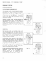
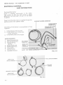
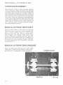
OPERATION
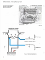
The Rockwell 2-cycle Twin Cylinder engine is of
the loop-scavenged third port type, the most
widely used design today. It uses a mixture of
gasoline, oil and air for combustion, lubrication
and cooling. It fires on every stroke of each
piston. There ore two power strokes for every
revolution of the crankshaft.
EXH/ UST
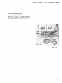
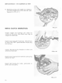
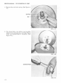
As the· piston moves upward in the cylinder it
draws the fuel/air mixture into the crankcase
through the intake manifold while at the some
time compressing fuel that has been forced into
the combustion chamber. See Fig. 1- 1A.
TRANSFER
As the piston nears top dead center the spark
plug is fired and the compressed fuel/air mixture burns and expands thereby forcing the
piston downward on a power stroke.
As the downward stroke of the piston turns the
crankshaft, it also starts to compress the
fuel/air
mixture
in
the
crankcase
and,
simultaneous ly, opens the exhaust port and
closes the intake port. See Figs. 1- 1 B & C.
FIG. 1-1
)
1-2
SERVICE MANUAL - 1975 SCORPION LIL' WHIP
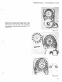
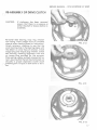
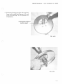
After the exhaust port is fully open and the intake port is fully closed, further piston travel
starts to open the transfer ports. The compressed fuel/air mixture from the crankcase
then travels up the transfer ports and into the
combustion area.
After most of the burned exhaust gases have
left the cylinder, an incoming charge of fuel/air
mixture scavenges the combustion area giving it
a fresh charge and the cycle is then repeated.
See Fig . 1-1 D.
Because lubrication is dependent on the m1xmg
of oil and fuel, it is extremely important that
good quality oil and gasoline are properly
mixed. The proper ratio of oil to gasoline wi ll
prevent possible engine overheating, piston or
cylinder scoring, or eventual engine seizure.
Too much oil and not enough gasoline can lead
to incomplete combustion, fouled plugs, carbon
build-up and muffler clogging.
)
( )
1-3
SERVICE MANUAL • 1975 SCORPION LIL' WHIP
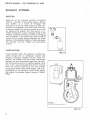
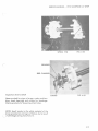
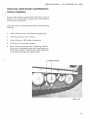
EXHAUST SYSTEMS
SELECTION
Selection of an exhaust system (including
exhaust manifold, intermediate pipes, elbows
and muffler), is a result of thorough test
procedures involving measurement of fuel consumption, horsepower and noise level. Contrary
to popular belief, the exhaust system is not only
for quieting the engine, but also serves to increase horsepower output. Changes made to the
original equipment exhaust system by changing
any component in the system can result in loss of
power and/or severe engine damage. For these
reasons, intermediate lengths of pipe betweeen
the cylinder and the muffler are particularly
critical.
Donaldson
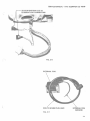
TUNED MUFFLERS
FIG. 1-2
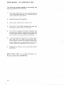
Tuned mufflers allow the engine to exhaust its
spent charge into an adequate volume and
properly matched muffling system. More important, the mufflers that are tuned, incorporate
designs that suck the exhaust gas from the cylinder allowing fuel and air to rapidly replace it and
also "cram" over-scavenged fuel and air mixture
from the exhaust pipe back into the cylinder
using sound waves and sound energy. This is accomplished at the speed of sound which allows
the engine to produce higher torque at higher
RPMs.
)
Tuning
Courtesy of Donaldson Muffler Co
l '
FIG. 1-3
1-4
SERVICE MANUAL - 1975 SCORPION LIL' WHIP
HOW TUNING WORKS
The megaphone effect of the expanded intake
tube scavenges exhaust gas from the cy linder
allowing rapid replacement of th e fuel/air mixture from the crankcase. Reflected sound waves
and sound energy stop over-scavenging and
return fuel/air mixture to the cylinder. It gives a
supercharging effect e ven though it operates
from the exhaust rather than the intake side.
Over-scavenging is also retarded by moderate
muffler back pressure. Silencing is accomplished
after power is maximized by acoustical packing in
the resonator outlet tube plus chambering and
baffling which gives an effective 2-pass muffler
design.
(
)
l'
l -5
SERVICE MANUAL - 1975 SCORPION LIL' WHIP
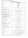
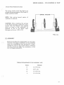
TABLE OF SPECIFICATION S
ENGIN E MODEL
2F 295-2
DESCRIPTION
BORE
2.190
(55.6mm )
STROKE
2.362"
(60mm)
DISPLACEMENT IN cc
COMPRESSION RATIO
294
(actua l)
12:1
IG NITION SYSTEM
Bosch Flywheel Magneto
LIGHTING COIL VOLT AGE AND
OUTPUT
12V 150W
*TIMING BEFORE TDC (CENTRIFUGAL
W EIGHT ADVANCED}
.102-.112
TIMING BEFORE TDC (CE NTRIFUGAL
W EIGHT RETARDED)
.0 18" to .020"
BREAKER POINT GAP
.014"to.Ol6"
)
.
SPARK PLUG THREAD
14mm . x 1.25 - 3/4" reach
SPARK PLUG GAP
.020"
(0 .5mm.)
SPARK PLUG-BOSCH (ORIGINAL
EQUIPMENT}
W260T2
..~~(~
TYPE OF ENGINE COOLI NG
ROTATION OF CRANKSHAFT
CARBURETOR
FUEL/OIL RATIO
GASOLINE
TYPE OF OIL
Axial Flow Fan
Counterclockwise (PTO side)
Walbro
As Specified on Scorpion Oil Container
95 octane, minimum (lead free not acceptable)
Special 2-Cycle Snowmobile Oil
* Do not exceed indicated advance, as thi s will re sult in severe eng ine damage.
1-6
SERVICE MANUAL - 1975 SCORPION LIL' WHIP
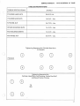
TABLE OF SPECIFICATIONS
TORQUE SPECIFICATIONS
2F 295-2
(
CYLINDER HEAD NUTS
28-32 Ft.-Lb.
CYLINDER BASE NUTS
16-18Ft.-Lbs.
FLYWHEEL NUT
56-72Ft.- Lbs.
INTAKE MANIFOLD NUTS
16- 18 Ft. - Lbs.
FAN HOUSING SCREWS
16-18 Ft. - Lbs.
FAN WHEEL NUT
22-24 Ft.- Lbs.
Tightening Sequence for Cylinder Base Nuts
All Models
J
PTO SIDE
Tightening Sequence for:
Cylinder Head Nuts, Fan Housing, Intake Manifold
and Recoil Starter Clamps
8
0
'75
290
)
1-7
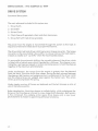
SERVICE MANUAL · 1975 SCORPION LIL' WHIP
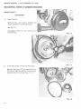
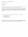
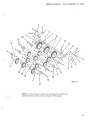
ROCKWELL TWIN CYLINDER ENGINES
MODEL 2F-295-2
J
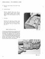
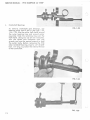
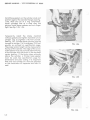
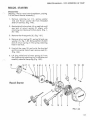
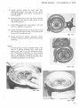
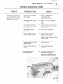
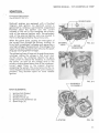
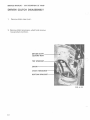
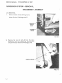
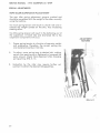
DISASSEMBLY
A.
Recoil Starter
Remove four (4) screws holding the
recoil assembly to the fan housing.
See Fig. 1-4.
See pages 1-28 A, B, C for recoil starter
disassembly.
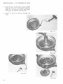
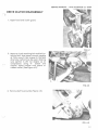
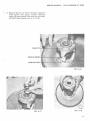
B.
Lower Fan Pulley and Carrier Assembly
FIG. 1-4
FIG. 1-5
Remove the three (3) hex head bolts on
the carrier. Remove carrier, lower pulley
assembly and V-belt. See Figs. 1-5, 1-6.
FIG. 1-6
1-8
SERVICE MANUAL - 1975 SCORPION LIL' WHIP
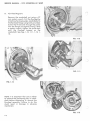
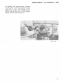
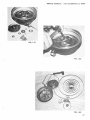
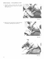
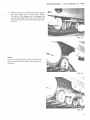
C.
Upper Fan Belt Pulley Assembly.
Insert a 3/16" drill or a suitable punch
through the indexing hole into the impeller body. With a 17 mm socket
wrench, remove the fan nut, lock
washer, pulley halves and spacers. See
Figs. 1-7,1-8,1-9.
FIG. 1-7
FIG. 1-8
(
FIG. 1-9
1-9
SERVICE MANUAL - 1975 SCORPION LIL' WHIP
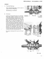
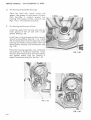
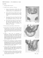
D.
Flywheel Magneto
Remove the crankshaft nut using a 27
mm socket wrench. Pull the flywheel by
attaching flywheel puller 444-31-843-2 to
the flywheel flange using bolts provided.
Screw the three bolts through the pull e r
into the flange and tighten evenly. With
a socket wrench, tighten the puller bolt
until the flywheel loosens on the
crankshaft. See Figs. 1-10, 1-11, 1-12, 113.
FIG. 1-10
)
FIG. 1-11
NOTE: It is important that care is taken
to remove the positioning key in crank shaft before attempting to remove the
flywh ee l assembly. Failure to do this
could result in damage to advance
m echani sm.
)
FIG. 1-13
l-1 0
SERVICE MANUAL - 197 5 SCORPION LIL' WHIP
(
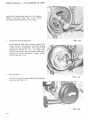
E.
Intake Manifold Assembly
Remove the four (4) intake manifold
nuts and washers. Remove manifold
assembly and insulators. See Fig. 1-14.
( _)
~
~Hfk(~;
oo
00
FIG. 1-14
l_..~
1-11
SERVICE MANUAL • 1975 SCORPION LIL' WHIP
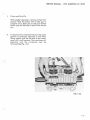
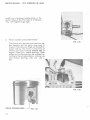
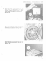
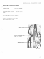
F.
Fan Housing and Armature Plate Assembly
Remove screw holding spark plug wire
bracket to fan housing. With a socket type 5
mm Allen wrench and impact driver, remove
the four (4) mounting bolts holding fan
housing to crankcase. (See Fig. 1-15).
Remove fan housing from crankcase (See
Fig. 1-16).
FIG. 1-15
Unplug connector housing coi l wires. (Note
color coding of wires.) Remove armature
plate assembly and wires, as a unit, from
fan housing.
FIG. 1-16
1-12
l)
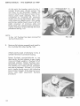
SERVICE MANUAL· 1975 SCORPION LIL' WHIP
Remove the fan QY tapping the end of fan
shaft with a soft hammer. With a flat punch
and hammer, tap the inner race of the furthest bearing in the housing. See Figs. 1-17,
1-18, 1- 19.
FIG. 1-17
)
FIG. 1-18
(
FIG. 1-19
1-13
SERVICE MANUAL - 1975 SCORPION LIL' WHIP
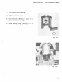
G. Remove spark plugs with spark plug
wrench.
H. Cylinder Heads
Remove cylinder head nuts
17 mm socket wrench. Mark
heads before removal from
Remove and discard gaskets.
1-20.
I.
with a
cylinde r
cylinder.
See Fig.
Cylinders
Remove the eight {8) cylinder base
nuts using a 13 mm socket wrench and
remove the eight (8) spring washers.
The cylinders may be removed . See
Fig. 1-21.
NOTE: I M P 0 R T A N T
FIG. 1-20
( )
If removal of cylinders only is required, care
must be taken that the crankcase seal is not
disturbed. The removal of the PTO cylinder
will allow the placement of two bolts and
nuts with flat washers to apply constant pressure to crankcase assembly. Bolts should be
placed in the center two holes (adjace nt to
the fan side cylinder). See Fig. 1-29. The
second cylinder may now be removed.
( )
FIG. 1-2 1
l -14
SERVICE MANUAL - 1975 SCORPION LIL' WHIP
J.
Piston and Wrist Pin
With needle nose pliers, remove
pistons. Heat the piston with a
propane torch. Heat only to the
piston may sti ll be held in hand.
out.
K.
circlips from
heat gun or
point where
Push the pin
To separate the crankcase halves, hold upper
portion of crankcase assembly in one hand,
lifting slightly and tap the end of the crankcase with a soft hammer. The crankcase will
separate and the crankcase may be
removed. See Fig. 1-22.
FIG. 1-22
J
1- 15
SERVICE MANUAL - 1975 SCORPION LIL' WHIP
L.
Crankshaft Bearings
To remove crankshaft end bearings, use
bearing puller 444-31-807-0. See Figs. 1-23,
1-24, 1-25. Slip the puller half shells around
the outer bearing race and around puller
assembly. Slide the retaining ring over the
half shells. Using two (2) 27 mm wrenches,
turn the center bolt clockwise with one
wrench and use the second wrench to hold
the puller body. Before removing the PTO
side crankshaft bearing, insert a 1/2" 20 UNF
bolt, 1/2" long, to protect the internal thread
of the crankshaft.
FIG. 1-23
FIG. 1-24
FIG. 1-25
1-16
SERVICE MANUAL • 1975 SCORPION LIL' WHIP
ASSEMBLY
)
A.
Crankshaft Bearings.
Heat crankshaft bearings in oil (or oven) to
approximately 180 degrees.
Slide bearing on crankshaft.
B.
(
t
Crankcase.
Inspect and clean both halves of crankcase.
The proper sealant material such as Permatex Hy-Tack Spray shou ld be now sprayed
on crankcase sea lin g surfaces. See Fig. 1-27.
Before installing crankshaft into crankcase
lower half of it will be necessary that al l
bearing outer surfaces be wiped clean of
foreign material so that proper sealing will
occur. After installing PTO thrust washer and
oi l sea l (inside groove of oil sea l coated with
li ght grease) place the crankshaft carefully
into the lower crankcase half and properly
position all componenets. See Figs. 1-28.
Placement of the upper crankcase half may
now be made. Be certain that the center seal
is lined up with the crankcase split line.
BEARING_j
FIG. 1-26
Tap upper crankcase half to seat with lowe r
half.
FIG. 1-27
\
,:l
FIG. 1-28
1-17
SERVICE MANUAL · 1975 SCORPION LIL' WHIP
r
Install two crankcase holding bolts in the
center holes of the PTO side of crankcase.
(Fig. 1-29) Tighten finger tight.
C.
Piston, Cylinder and Cylinder Heads
FIG. 1-29
The pistons must be clean and free from carbon deposits and the piston rings must fit
freely in their grooves. Rings are marked for
proper side up. The arrow on the crown of
pistons must point toward exhaust side of
engine. Piston pins, needle bearings, check
plates and circlips may now be installed, according to the procedure below. (Always use
new circlips.) See Figs. 1-30, 1-31, 1-32, 133).
FIG. 1·30
_;
CIRCLIP OPENING HERE----r
1-18
FIG. 1-31
SERVICE MANUAL · 1975 SCORPION LIL' WHIP
1.
O il the piston pin e nd bearings.
2.
In sta ll one circl ip in piston.
3.
Heat the piston suff icien tly to allow pin to
push into p iston and install pin.
4.
In sta ll second circlip. (See Fig.
correct orientation of circlips. )
1-3 1 for
0
FIG. 1-32
(
FIG. 1-33
\ ,,
J ·19
SERVICE MANUAL · 1975 SCORPION LIL' WHIP
)
Install base gaskets on the cylinder studs and
position against the cylinder flanges (see Fig.
1-34). With the use of a ring compressor,
lower cylinders one at a time over the
pistons. Install base washers and nuts finger
tight. See Fig. 1-35, 1-36.
Temporarily install the intake manifold
without gaskets and tighten manifold nuts to
sixteen (16) to eighteen {18) foot pounds.
See Fig. 1-37. Cylinder base nuts may now be
torqued to sixteen {16) to eighteen {18) foot
pounds as outlined on specification page.
The proper piston height can be measured at
the top of the cylinder. The edge of the crown
of the piston must not protrude above the top
of the cylinder with the piston in the top dead
center position. If the piston does protrude
above the cylinder, a thicker base gasket
must be used. See specification page for
dimensions and color coding. It is important
that only one cylinder at a time be adjusted
or the crankcase will separate and lose it's
seal.
FIG. 1-34
)
FIG. 1-35
FIG. 1·36
1·20
SERVICE MANUAL - 1975 SCORPION LIL' WHIP
Oil cylinders and pistons before installing
cylinder heads. Install head gaskets with the
wide side of inner metal flange of the
gaskets up toward the cylinder heads.
Torque cylinder head nuts to twenty-eight
(28) to thirty-two (32) foot pounds.
FIG. 1-37
1-21
SERVICE MANUAL · 1975 SCORPION LIL' WHIP
D.
Fan Housing and Impeller Bearings
Clean fan shaft hub. Install circlips and
spacer. Use grease to hold spacer in place.
Pack bearings in medium grease into
housing with sealed surface outward. See
Figs. 1-18, 1- 19. Install fan and shaft.
E.
Fan Housing and Armature Plate.
Install new seal in fan housing. lubricate the
inner groove of the oil seal with a light
grease. See Fig. 1-38.
Install new o -ring and apply sealant material
around o -ring surface (see Fig. 1-41). Install
the armature plate wires through hole in fan
housing and install armature plate with hold
down screws, washers, and lockwashers. See
Fig. 1-39.
Place fan housing assembly over crankshaft
and position to crankcase assembly. Install
the four Allen head screws and lockwashers
and tighten evenly until fan housing is
against crankcase assembly. See Fig. 1-40.
FIG. 1-38
FIG. 1-39
FIG. 1-40
1-22
SERVICE MANUAL - 1975 SCORPION LIL' WHIP
Torque to sixteen (16) to eig hteen (18) foot
pounds. Connect ignition wires to ext ernal
ignition coi l and to connector ho using. Check
ground wires for proper position. Install
ignition cable bracket to fan hou sing.
F.
Intake Manifo ld
Install spacers. gaskets and intake manifo ld
(Fig. 1-4 1) . Torque nuts evenly to sixteen
(16) to (18) foot pounds.
G.
Upper Fan Pulley A ssemb ly
Install the tapered wa she r. Install pulley half,
shims, second pulley half, tapere d washer,
lock washer and nut. Use 3/ 16" drill bit or
punch to hold fan assembly and ti g hten nut.
See Fig. 1-42.
FIG. 1-41
H.
Flywheel A ssembly
Check advance mechanism for free
operation, lubricate in side cam surface
(Grooved area). Slide assembly ove r
crankshaft and align key ways.
1-23
SERVICE MANUAL - 1975 SCORPION LIL' WHIP
Install key, lockwasher and nut in that order.
Tighten securely. See Fig. 1-43. Follow
Timing Procedure Section as next step.
I.
lower Fan Pulley Assembly
FIG. 1-43
Install pulley half, belt, second pulley half,
recoil carrier, lockwashers and bolts evenly
while rotating crankshaft. The proper belt
deflection should be 1/8" on each side.
Proper adjustment can be made by adding or
removing shims between upper pulley
halves. See Fig. 1-44.
J.
Recoil Starter
Install the recoil starter assembly and tighten
securely. See Fig. 1-45.
FIG. 1-44
FIG. 1-45
1·24
SERVICE MANUAL - 1975 SCORPION LIL' WHIP
RECOIL STARTER
Disassembly
~
(See Fig. 1-46 for recoil start breakdown, and Fig
1-47 for Recoil Starter Assembly.)
l. Remove retaining nut (11), spring washer
(12) and Thru st washer (8) from threaded
shaft of reel hub. (Fig. 1-48).
2 . Manipulate friction plate (4) on reel hub until
eye end of return spring (9) aligns with
retaining slot. Remove friction plate. (Fig. 149, 1-50).
3. Remove the three pawls (3), (Fig. 1-51).
4. Remove return spring (9), spring (6) and cup
washer (7). Fig. 1-50. Note position of plain
end of return spring in the spring retaining
hole in reel hub.
5. Unwind the rope; lift and untie the knotted
end from center hub of reel, remove reel (2).
(Fig. 1-52).
6. Lift long rolled end of main spring (5) from
the fixed spring retaining pin in th e case and
carefully remove the spring (Fig. 1-53).
11
12
8 21 4
9
6
7
3
2
10
18
19
20
Recoil Starter
14
3
14
13
3
5
FIG. 1-46
1-25
SERVICE MANUAL - 1975 SCORPION LIL' WHIP
7. Clean a l l parts, except rope, using a suitable
cleaning solvent. If rope requires cleaning,
wash it in a solution of soap and water.
Thoroughly dry all parts after cleaning.
8. Inspect all parts for obvious damage and
wear.
FIG. 1-47
FIG. 1-48
~ .
~·
\·· .'" '
Q 0",.
'
'
'
FIG. 1-49
0 ~-~··
0
FIG. 1-50
1-26
SERVICE MANUAL - 1975 SCORPION LIL' WHIP
FIG. 1-5 1
\
FIG. 1-52
FIG. 1-53
1-27
SERVICE MANUAL - 1975 SCORPION LIL' WHIP
Assembly
1. Replace defective parts.
2. Install main spring as follows:
a.
Secure main spring winding tool, part
number 43-0797-60, or equivalent tool,
circular end up, in a suitable bench vise.
b.
Start with the long rolled end of main
spring (5) and wind spring into circular
end of tool in a clockwise direction. (Fig.
1-54).
c.
Remove tool from vise. Grasp the tool by
its handle and lower the tool, with
spring installed, into case (1) (Fig. 1-55).
d.
Secure the long rolled end of spring over
the fixed spring retaining pin. (Fig. 156). Remove winding tool (Fig. 1-57).
Apply a light film of Lubriplate, or
equivalent, to spring.
FIG. 1-54
3. Secure case, open side up, in bench vise.
4. Tie a knot at one end of the rope. Secure
knotted end in the center of reel (2). Pull
rope taut and wind entire rope around reel in
an anti-clockwise direction until the free end
protrudes through the notched section of the
reel.
5. Apply a light film of Lubriplate, or
equivalent, to center hub of case and install
the reel. Push down and rotate reel in an
anti -clockwise direction until the hook engages with the free end of main spring. Tension will be felt when reel and spring are properly engaged. (Fig. 1-58, 1-59).
FIG. 1-55
6. Rotate reel a maximum of three complete
turns in an anti-clockwise direction. Do not
exceed three turns; hold reel in this position
and feed free end of rope through case at the
rope guide hole. Install rope guide. Loosely
knot the rope to prevent recoil.
7. Apply a light film of Lubriplate or equivalent
to pawls (6) and install them on the reel in
the pawl retainers. (Fig. 1-60). (See Fig. 1-46
for part identification numbers.)
8. Install cup washer (7) flat side down, spring
(6) and return spring. Ensure that plain end
of return spring is properly engaged in the
retaining hole in reel hub.
1-28
FIG. 1-56
SERVICE MANUAL - 1975 SCORPION LIL' WHIP
9. Install friction plate (5) over reel hub.
Manipulate plate until eye end of return
spring engages and locks crosswise in
retaining slot.
10. Rotate friction plate until the three notches
are aligned with pawls when pawls are at
the recoil position.
11. Install flatwasher (8), lockwasher (12) and
nut (11 ). Tighten nut secure ly.
12. Untie the temporary knot in free end of rope
and install the rope handle. Tie a permanent
knot and fit handle securely.
FIG. 1-57
13. Check starter for proper operation. When
handle is pulled outward, pawls should move
outward.
NOTE:
If main spring is to be installed without the
use of a spring winding tool, wind main
spring into case in an anti -clockwise direction. Clockwise installation on the winding
tool is necessary to ensure correct anticlockwise installation of the spring when tool
is placed upside down in the case.
FIG. 1-58
FIG. 1-59
FIG. 1-60
1-29
SERVICE MANUAL - 1975 SCORPION LIL' WHIP
TIMING PROCEDURE
(
NOTE: Recoil starter, carrier, lower pulley assembly and spark plugs should be removed before
beginning timing procedure.
A.
Install the dial indicator assembly into spark
plug hole of No. 1 cylinder (P.T.O. side). See
Fig. 1-61.
B.
Attach negative lead of ohmmeter to engine
ground. Attach positive lead of ohmmeter to
No. 1 cylinder terminal in connector housing.
See Fig. 1-62.
C.
FIG. 1-61
Rotate flywheel
counterclockwise until
points are on the high side of cam on No. 1
cylinder. Points are at maximum open position observed through opening in flywheel.
Check gap with wire gauge and adjust to
.015 if necessary. See Fig. 1-63.
FIG. 1-62
FIG. 1-63
1-30
SERVICE MANUAL · 1975 SCORPION LIL' WHIP
(
D.
Rotate flywheel
dead center and
selector knob on
meter needle will
See Fig. 1-64.
counterclockwise to top
adjust dial to zero. Place
ohmmeter to R x 1. Ohmindicate a closed circuit.
FIG. 1-64
Move the centrifugal weights in flywhee l to
the full advanced position. See Fig. 1-65.
('
Rotate flywheel counterclockwise one complete revolution to between . 102 and . 112.
See Fig. 1-66.
FIG. 1-65
FIG. 1-66
1-31
SERVICE MANUAL · 1975 SCORPION LIL' WHIP
At this point the breaker points for No. 1
cylinder should open. (Break contact) This
will show on the ohmmeter. Needle will
move to the left. If this does not occur, the armature plate needs adjusting. This is accomplished by loosening the hold-down
screws and turning plate either left or right
while observing needle action. With proper
positioning, needle should move to left with
slight movement of armature plate and
flicker back with opposite plate movement.
Tighten hold-down screws securely. Re-check
procedure. See Fig. 1-67.
NOTE:
In Fig. 1-67 flywheel has been removed for
clarity of illustration.
E.
)
FIG. 1-67
Remove dial indicator assembly and install in
No.2 cylinder (fan side). See Fig. 1-68.
Attach positive lead of ohmmeter to No. 2
cylinder terminal in connector housing.
J
Rotate flywheel counterclockwise to top
dead center. Set dial indicator to zero. Again
move centrifugal weights in flywheel to full
advanced position. Rotate flywheel counterclockwise while watching dial indicator.
The needle must make one full revolution
and stop at between .1 02 and .112. At this
point, needle should move to left indicating
point contact (closed). If this does not occur,
points need slight adjustment. Re-check
procedure.
FIG. 1-68
1-32
SERVICE MANUAL - 1975 SCORPION LIL' WHIP
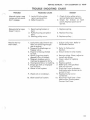
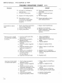
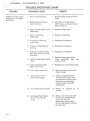
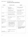
TROUBLE SHOOTING CHART
TROUBLE
PROBABLE CAUSE
Manual starter rope
come s out but pawls
don't engage.
1. lack of friction plate
return spring action.
2. Defective pawls.
Manual starter rope
doesn't return.
1. Recoil spring broken or
bent.
2. Pulley housing warped or
bent.
3 . Starting pulley worn.
Hard to start or
won't start.
1. Carburetor adjustments too
lean (not allowing enough
gas to engine).
2. Inoperative diaphragm or
flapper valve.
3. Engine not being choked
to start.
4. Spark plugs improperly
gapped, dirty or broken.
5. Magneto breaker points
improperly gapped or dirty.
6. Head gasket blown or leaking.
7. Empty gas tank or improper
fuel mixture.
8. Water in fuel system.
9 . Weak coil or condenser.
10. Obstructed fuel system .
REMEDY
1. Check friction plate returnspring. Replace as required.
2. Check for br.oken or bent
pawls. Replace pawls as required.
1. Replace spring.
2. Replace housing.
3. Replace pulley.
1. Adjust carburetor. Refer to
Carburetor Section
2. Refer to Carburetor
Section.
3. Ensure choke is fully closed.
4. Remove plugs. Clean, adjust or
install new plugs.
5. Clean, adjust or replace
points.
6. Replace gasket.
7. Refill tank with specified
fuel/oil mixture.
8. Drain fuel from carburetor.
Add carburetor de-icer as required to fuel.
9. Replace faulty coil or
condenser.
10. Disconnect fuel lines- clear
obstruction. Flush system.
Connect fuel lines.
1-33
SERVICE MANUAL . 1975 SCORPION LIL' WHIP
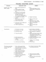
TROUBLE SHOOTING CHART
TROUBLE
12. Engine not tim ed properly.
13. Secondary wire not
connected or spark plug
protector not installed
properly.
Impossib le to adjust
idl e.
Mi ssing at low speed
or won't idle smoothly
or slowly.
1. Spark retarding mechanism
not working properly.
2. Pistons or rings worn .
3. Faulty carburetor.
1. Incorrect carburetor idle
2.
3.
4.
5.
6.
7.
8.
Missing at high speed
or intermittent spark.
r
1-34
I
REMEDY
PROBABLE CAUSE
10. Air leak in crankcase or
inlet system.
11. Primary wire broken.
adjustment.
Spark plugs improperly
gapped or dirty.
Head gasket blown or
leak ing.
Loose or broken magneto
wires.
Magneto breaker points
improperly gapped or
dirty.
W eak coil or condenser.
Improper fuel mixture.
(1) Too much oil
(2) Too littl e oil
Leaking crankshaft seal.
1. Spark plugs improperly
gapped or dirty.
2. Loose or broken magneto
wires.
3. Magneto breaker points
improperl y gapped or dirty.
4. Weak coil or condenser.
5. Heat range of spark plug
incorrect.
6. Leaking head gasket.
7. Engine improperly timed.
ccoNr.)
r
10. Check crankcase pressure
(3-6 PSIG)
11. Repair or rep lace primary
wire.
12. Re-time engine.
13. Secure secondary wire or
spark plug protector.
1. Repair retard mechanism.
2. Replace as necessary.
3. Check carburetor, check valve.
Refer to Carburetor
Section.
1. Adjust idle-Refer to
Carburetor Section.
2. Clean, adjust or install new
plugs.
3. Replace gasket.
4. Repair or replace wires.
5. Adjust, clean .or install new
points.
6. Replace coil or condenser.
7. Refuel, using specified fuel/oil
mixture.
8. Replace seal.
1. Clean, adjust or install new
plugs.
2. Repair or replace wires.
3. Clean, adjust or install new
points.
4. Replace coil or condenser.
5. In stall specified spark plugs.
6. Replace head gasket.
7. Re-time engine.
(
SERVICE MANUAL · 1975 SCORPION LIL' WHIP
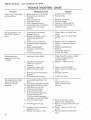
TROUBLE SHOOTING CHART
REMEDY
PROBABLE CAUSE
TROUBLE
(
)
Coughs, spits, slows
down, surges
1. Idle or high speed jets too
lean.
2. leaking gasket flange.
3. Inlet control level set too
low.
4. Pulsation line obstructed.
5. Fuel pump not supplying
enough fuel due to:
(1) Punctured diaphragm.
(2) Inoperative flapper valve.
6. Crankcase not properly
sealed.
7 . Idle or main carburetor
nozzle obstructed.
8. Fuel line obstructed.
9. Carburetor inlet needle and
seat obstructed.
10. Welch plug leaking.
Overheating
r )
1. to 5.
Adjust carburetor or fuel
pump. Refer to Carburetor
Section.
6. Reseal crankcase.
7. Refer to Carburetor
Section.
8. Remove fuel line. Clear
obstruction. Replace line.
9. Refer to Carburetor
Section.
10. Refer to Carburetor
Section.
1. and 2. Adjust carburetor.
Refer to Carburetor Section.
l. Carburetor too lean.
2. Carburetor too rich.
3. Incorrect timing.
3. Retime engine to Specifica-
4. Too much carbon.
4. Remove cylinder heads. Clean
5. Spark plug too hot.
6. Engine fan belt loose or
top of pistons and inside
compression chamber. Clean
out exhaust port.
5. Install specified spark plugs.
6. Replace or adjust.
tions.
broken.
7. Air leak in manifold.
7. Tighten nuts or change
8. Crankcase seal leaking.
8. Fit new seal.
1. Idle or high speed carburetor adjustment too rich.
2. Choke not opening properly
(bent linkage).
3. Inlet control lever too
high. (carburetor floods)
4. Idle air bleed plugged.
5. Welch plug loose.
6. Muffler obstructed.
7. Engine not secured tightly
to engine support.
8. Water in gas.
1 to 5. Adjust carburetor. Refer
to Carburetor Section.
gaskets.
Vibrates excessively
or runs rough and
smokes.
)
6. Check and clear muffler.
7. Tighten engine mounting
bolts.
8. Add carburetor de-ice fluid
as required.
1-35
SERVICE MANUAL . 1975 SCORPION LIL' WHIP
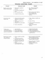
TROUBLE SHOOTING CHART
TROUBLE
Won't start, kicks back
and backfires.
1.
2.
3.
4.
5.
6.
No acceleration, low
top R.P .M., hard to
start.
Good spark but
engine runs on one
cylinder.
PROBABLE CAUSE
Spark plug wires reversed.
Flywheel key missing or
sheared.
Faulty condenser.
Improper timing.
Faulty breaker points.
Unhooked spark retarding
mechanism- or spring
broken.
1. Spark plugs improperly
gapped or dirty.
2. Magneto breaker points
improperly gapped or
dirty.
3. Faulty coil or condenser.
4. loose or broken magneto
wires.
5. Blown head gasket.
6. Inlet lever adjustment
too low.
7. Crankcase leaking.
1. Leaking cylinder head.
REMEDY
1. Install wire correctly.
2. Replace key.
3.
4.
5.
6.
Replace condenser.
Re-time engine.
Adjust or replace points.
Reconnect mechanism or
replace spring.
1. Clean, adjust or install new
plugs.
2. Clean, adjust or insta l l new
points.
3. Replace coil or condenser.
4. Repair or replace magneto
wires.
5. Replace head gasket.
6. Refer to
Carburetor Section.
7. Install new seal.
1. Check head for warps, cracks.
Install new gasket and
cylinder head.
2. Repair c-r replace wires.
2. Magneto wires broken
inside (coil ground
broken).
3. Cracked cylinder wall.
4. Defective spark plug.
3. Replace faulty cylinder.
4. Clean, adjust or install new
5. Breaker points improperly
5. Re-adjust points.
plug.
gapped.
No acceleration. Idles
well but dies down
when put to full
throttle.
6. Crankcase seal leaking.
6. Install new seal.
1. low speed needle set too
lean.
2. Dirt behind needle and seat.
3. High speed jet obstructed.
4. In let lever set too low.
5. Choke partly closed.
6. Silencer obstructed.
7. Fuel pump not supplying
enough fuel due to:
( 1) Punctured diaphragm
(2)Fiapper valves distorted.
8. Fuel line obstructed.
1. to7.
Adjust carburetor.
Refer to Carburetor
Section.
8. Remove fuel line. Clear
9. Not enough oil in gas.
9. Refuel , using specified fue l/oil
obstruction. Replace line.
10. Breaker points improperly
gapped or dirty.
11. Engine improperly timed.
1-36
mixture.
10. Adjust, clean or install new
points.
11. Re-time engine to specifications.
(
SERVICE MANUAL · 1975 SCORPION LIL' WHIP
TROUBLE SHOOTING CHART
TROUBLE
Engine runs by using
choke at high speed.
REMEDY
PROBABLE CAUSE
(
l. High speed needle set
l. & 2. Adjust carburetor.
Refer to Carburetor
Section.
too lean.
2. Dirt behind needle and
seat.
3. Fuel line obstructed.
3. Remove line, clear obstruc-
4. Inoperative fuel pump.
4. Refer to Carburetor
tion, replace line.
Section.
No power under
heavy load.
l. Magneto breaker points
l. Clean, adjust or install new
points.
improperly gapped or
dirty.
2. Ignition timing too far
advanced.
3. Magneto coil plate loose.
3. Check magneto and secure
4. Faulty carburetion.
4. Refer to Carburetor
2. Adjust timing.
coil plate.
Section.
(
Cranks over
extremely easy on
one or both cylinders.
Loss of compression.
1.
2.
3.
4.
Scored piston.
Blown head gasket.
Loose spark plug.
Head bolts not tight.
Engine won't crank
over. Unable to
rotate flywheel.
l. Piston rusted to cylinder
wall.
2. Crankshaft seized to
bearing. (main or rod)
3. Broken connecting rod.
4. Flywheel seized to coil
plate.
5. Engine improperly
assembled after repair.
1.
2.
3.
4.
Replace faulty piston.
Replace head gasket.
Check plug for security.
Torque head bolts to proper
specifications.
l. Remove piston and cylinder.
Replace defective parts.
2. &3. Disassemble engine.
Replace defective parts.
4. Remove flywheel. Replace
defective parts.
5. Recheck re-assembly
procedure.
l-37
f
)
(
1975
Scorpion
Lil Whip
Service Manual
Carburetor
Section
2- 1
SERVICE MANUAL - 1975 SCORPION LIL' WHIP
Functional Description:
f
General ·
The purposes of the carburetor are ( 1) to provide the amount of fuel that the engine needs in
operation and (2) to properly mix the fuel with air so that it will vaporize.
Pulsations from the crankcase through the impulse tube, actuates the carburetor fuel pump
diaphragm to move the fuel into the carburetor from the fuel lines. An increased engine fuel
demand causes a reduced pressure at the metering diaphragm which opens the needle valve .
More fuel enters through the needle valve into the carburetor bore where it is mixed with in coming air.
The four operational phases of the Walbro Carburetor used on the 1975 Lil Whip are:
{1)
(2)
(3)
{4)
Starting (choke) operation
Idle operation
Part-throttle operation
Full-throttle operation
Detailed performance of the carburetor in each of the four phases is described below. Figures
2-1 through 2-4 are schematic diagrams and as such are accurate, functional representations
of the carburetor, but in some features deviate from actual physical appearance.
(
2 -2
SERVICE MANUAL - 1975 SCORPION LIL' WHIP
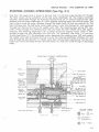
STARTING (CHOKE} OPERATION (See Fig. 2-1}
Fuel from the supply tank is drawn in the fuel inlet (1) into the surge chamber (2) through
the filter screen (3) by pulsations of the fuel pump diaphragm (4). The engine crankcase
pulsation transmitted through the external impulse fitting (9) or internal impulse hole (9A)
actuates the fuel pump diaphragm (4) which supplies pumping action for the fuel pump. The
fuel is drawn from the surge chamber through the check valve (5) and the channel (6). The
fuel continues past the fuel pump outlet check valve (7) and into channel (8). Fuel continues
through fue l channel (8) and to the needle valve (28). The metering lever spring (29) transmits a force through the metering lever (30) and seats the inlet needle valve (28) against
pressure. The metering diaphragm (1 O) is pulled upward by engine suction which is transmitted through the idle discharge port idle hole (14) secondary idle holes (16) and part
throttle feed holes (17). The diaphragm action depresses the metering lever (30) and unseats
the needle valve (28) and allows the fuel to enter the metering diaphragm chamber (31) and
pass through the idle take off (11). Check valve (32) is forced open passing fuel into the main
nozzle (21) which also feeds the part throttle holes (17). Fuel only is fed through all discharge
holes.
STARTING
(CHOKE) OPERATION
)
Power needle
Choke valve
"closed"
-+-- - -- /
Outlet check
valve (7)
COLOR CODE
l
Vapor return
Air
Fuel
l Fuel inlet
_j
Crankcase
•...
....
·-·.
Impulse Air
Fuel
I Vapor
2-3
SERVICE MANUAL · 1975 SCORPION LIL' WHIP
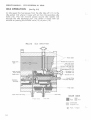
IDLE OPERATION
(See Fig. 2-2)
At idle speed the fuel passes from the idle take off (11) to the
idle pocket (13) where it mixes with air from the secondary idle
holes (16). This rich mixture passes around idle needle (12)
through the idle discharge port (14) where it mixes with additional air passing the throttle valve (19) at point (15).
FIG. 2-2
L
IDLE OPERATION
Power needle
Secondary
fuel pump
COLOR CODE
1V~por return
1fuel
inlet
Fuel
Air
Crankcase
Impu lse Air
:;:: Fuel
···
..
2-4
I Vapor
SERVICE MANUAL . 1975 SCORPION LIL' WHIP
PART THROTTLE OPERATION
(See Fig. 2-3)
At part throttle, in addition to the fuel fed into the throttle bore
by the idle system, more fuel enters past the check valve (32)
through passage (26) around the power needle (22) and through
the passage ( 18) and discharged into the throttle bore (20)
through the part throttle holes (17) . All ports except the main
nozzle feed progressively as throttle valve opens for smooth acceleration. Air is intermixed through air bleed nozzle (25).
FIG. 2-3
PART THROTTLE OPERATION
(
(22)
Venturi
(23)
Choke valve (24)
Throttle valve
( 19)
Main nozzle
Throttle bore
Part throttle holes
(21)
(20)
(17)
(16)
(14)
Air bleed
nozzle (25)
Needle valve (28)
Passage
(18)
Idle needle
Passage
(12)
(26)
Check valve
(32)
. Impulse fitting
.
(9)
,;~"; ~
Fuel pump d iaphragm
(4)
Vapor return line f itting
to f uel tank
l
1Vapor return
~ Fuel
inlet
2 -5
SERVICE MANUAL • 1975 SCORPION LIL' WHIP
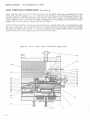
FULL THROTTLE OPERATION
(See Fig. 2-4)
Note: Starting, idle, and part throttle operations of the WDA carburetor are identical to that
of the WD and WR models. You will notice the main difference is the discharge of fuel at full
throttle operation. The WR discharges fuel through #(21) main nozzle, at only the base of the
power needle, where as the WD and WDA discharge at five discharge ports parallel to power
needle (22). This is noted by comparing Fig. 1 and Fig. 4.
At full throttle operation fuel passes around the power needle (22) and is discharged through
the main nozzle (21). During full throttle air is mixed with fuel in the main nozzle (21) through
the nozzle air bleed (25). Suction (or vacuum) created by the engine's piston action draws fuel
and air as the ports are exposed by position of the throttle valve.
FIG. 2-4
FULL
(WIDE OPEN) THROTTLE OPERATION
22
)
19
24
21
18
17
16
15
14
13
12
11
9A
10
9
23
26
27
28
29
30
31
32
33
4A
34
35
36
37
1
2-6
2
3 4
5
6
)
SERVICE MANUAL · 1975 SCORPION LIL' WHIP
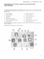
DISASSEMBLY OF PLATES, GASKETS AND DIAPHRAGMS
FOR CLEANING
To remove the p lates, gaskets and diaphragms from the lower part of the carburetor body,
remove the four mounting screws. Lay each part on a clean surface in the sequence removed.
(See FIG. 2-5)
1.
Cover Assembly
8.
Fuel Pump Diaphragm
2.
Fuel Inlet Gasket
9.
Fu e l Pump Gasket
3.
Fi Iter Screen
10.
Fuel Pump Leaf Gasket
4.
Filter Plate
11.
Valve Springs (3)
5.
Check Valve Diaphragm
12.
Pressure Spring
6.
Fuel Pump Check Valve Gasket
13.
Metering Diaphragm Assembly
7.
Fuel Pump Plate
14.
Metering Diaphragm
Chec~ diaphragms and gaskets thoroughly for cracks or leaks, by holding them against light.
Clean as required.
Reassemble in reverse seque nce o f disassembly.
12
(
'\
B
<D>
10
0
0
I
~
FIG. 2-5
2-7
SERVICE MANUAL • 1975 SCORPION LIL' WHIP
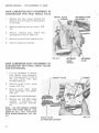
MAIN CARBURETOR BODY DISASSEMBLY IN
CONJUNCTION WITH INLET NEEDLE VALVE
1.
Remove the four screws holding the
plates to the main body and disassemble
in one mass.
2.
Remove metering lever pin screw. (FIG.
2-6)
3.
Remove metering lever. Watch
spring does not fly out. (FIG. 2-6)
4.
Remove spring and Inlet Needle Valve.
5.
Clean or replace as required.
that
METERING
LEVER
SPRING
MAIN CARBURETOR BODY DISASSEMBLY IN
CONJUNCTION WITH FINAL CHECK VALVES
AND DIAPHRAGMS.
1. It is not necessary to remove
Inlet Needle Valve assembly,
but it may be easier to work in
this area without them. (See
Procedure Above).
2.
Remove three circuit plate
screws. (FIG. 2-6)
3.
Remove circuit plate, check
valve diaphragm and gasket.
(FIG. 2-7)
4.
Inspect check valve diaphragm.
5.
Remove low and High speed
needles, if necessary, for
cleaning, grooves, channels,
etc.
)
CIRCUIT PLATE
NOTE • DO NOT REMOVE SCREEN
UNDER HIGH SPEED NEEDLE. CARBURETOR WILL NOT FUNCTION
WITH SCREEN REMOVED. (See FIG.
2-7)
CHECK VALVE
DIAPHRAGM & GASKET
2-8
METERING
LEVER
FIG. 2-7
SERVICE MANUAL · 1975 SCORPION LIL' WHIP
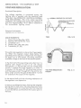
SPECIAL ADJUSTMENTS/TESTS
High Speed Adjustment:
(
The Factory setting of the High Speed Needle on
the carburetor is approximately 1 1/4 turns open.
However, each machine requires individual adjustment for optimum performance. A typical
curve showing the relationship between ENGINE
RPM (maximum operating) and HIGH SPEED CARBURETOR SETTING is shown in FIG. 2-8.
To determine the optimum high speed setting,
operate the machine with decreasing high speed
jet settings starting at 1 1/2 turns open, decreasing
in 1/8 turn increments. When the maximum normal operating engine speed reaches 6750 RPM,
that is the optimum setting.
At settings 1 richer (more turns open) than optimum, speed of the machine will drop off and
cylinders, pistons and plugs will have carbon
buildup. Engine may not start due to flooding.
CARBURETOR HIGH SPEED SETTING
(TURNS)
OVER RICH
I
I
LEVEL OFF '
DROPffl\
OPTIMUM SETTING
INCREASING TURNS OPEN
ENGINE
RPM
FIG. 2-8
INCREASING
RPM
At settings leaner (less turns open) than optimum, speed of the machine tends to level off or
increase slightly. Such increase is insignificant in
normal operation, and there is an attendant increased likelihood of burned plugs or pistons.
Variables which will affect the optimum high
speed carburetor setting are:
a.
Temperature - As temperature drops, the air
becomes more dense and the pumping
diaphragm less flexible. Both conditions
require a richer setting (more turns open) on
the high speed needle.
b.
Air Density (altitude) -At higher altitudes, it
is necessary to set the carburetor leaner
(less turns open).
So when marked changes in temperature or
altitude are experienced, it is advisable to adjust
the carburetor high speed needle.
NOTE: The 290cc. Lil Whip is equipped with a
WRA-37 carburetor. It is essential for optimum
performance, not to replace the high speed
needle from this carburetor with that of another
vintage Walbro carburetor, as the metering portion may be different.
)
2-9
SERVICE MANUAL • 1975 SCORPION LIL' WHIP
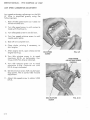
LOW SPEED CARBURETOR ADJUSTMENT
Low speed carburetor adjustment on the 290
Lil' Whip is simplified greatly using the
following steps:
1. Back off idle speed screw so it does not
contact throttle arm.
2. Turn idle speed screw in until contact is
made with throttle arm.
3. Turn idle speed screw in one full turn.
4 . Turn low speed mixture screw in until
needle seats lightly.
5. Back off one complete turn.
6. Close choke, priming if necessary, to
start engine.
7. After engine starts, open choke and let
engine warm up.
IDLE SPEED
SCREW
8. Turn idle mixture screw in to reach
maximum R.P.M. on tachometer. Continue until R.P.M. drop is indicated.
FIG. 2-9
HIGH SPEED
ADJUSTING SCREW
(NEEDLE)
9. Turn idle mixture screw out to reach
maximum R.P.M. Continue out until
R.P.M. drop is indicated.
10. Set idle mixture screw half way between
drop points. This is correct idle mixture
adjustment.
11. Adjust idle speed screw to obtain 2,200
R.P.M.
IDLE MIXTURE
SCREW
2-10
FIG. 2·1 0
)'
SERVICE MANUAL · 1975 SCORPION LIL' WHIP
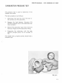
CARBURETOR PRESSURE TEST
The pressure test is used to determine if the
needle valve leaks.
The test procedure is as follows:
1.
Disconnect the fuel line from the fuel inlet connector on the carburetor.
2.
Connect the leak detector (Scorpion P/N
907000) pressure line to the carburetor fuel
inlet connector.
3.
Remove the carburetor vapor return line and
hold your finger over the carburetor fitting.
4.
Pressurize the carburetor with the leak
detector plunger pump. Do not exceed 12
PSI.
The needle valve, properly seated, should hold a
constant 8 psi.
(
FIG. 2-11
2-11
SERVICE MANUAL - 1975 SCORPION LIL' WHIP
)
2- 12
SERVICE MANUAL · 1975 SCORPION
TROUBLE SHOOTING CHART
r
TROUBLE
Excessive carbon buildup in engine & on spark
plugs or e ngine flooding.
(Fuel Rich Condition)
PROBABLE CAUSE
1. Foreign obstacle under
inlet needl e.
2. Diaphragm leve r adjust ment OFF.
3. Metering lev e r spring
not seate d in dimple on
metering lever.
4. leaking fuel pump
diaphragr.1.
5. Fore ign matte r under
umbre lla check valve.
6. Wron g an g le, or abused
m et e rin g po rtion o f hig h
spee d needl e.
7. leaking check valve in
primer.
8. Choke cable is not
activating choke .
(
1
FIG. 2-12
2-13
.<.:E MANUAL · 1975 SCORPION LIL' WHIP
TROUBLE SHOOTING CHART
TROUBLE
Engine runs hot, spark
plugs burn. (Fuel lean
condition)
PROBABLE CAUSE
REMEDY
1. Dirt in fuel channels.
1. Disassemble, wash and blow
clean.
2. Metering lever adjustment incorrect.
2. (See FIG. 2-13) Should be
.020'' above surface of valve
body as shown.
3.
3. Replace diaphragm.
Leaky nozzle check valve
diaphragm.
4. Hole in metering
4. Replace diaphragm.
diaphragm.
5. Impulse line leaking
5. Replace as necessary.
or pinched.
6. Intake manifold gasket
6. Replace as necessary.
leaking.
7. Leaking insulation plate
7. Replace as necessary.
between carburetor and
manifold.
8. Leaking diaphragm check
valve.
9. Fuel pump diaphragm
8. Replace diaphragm check
valve assembly. (See procedure P 2-8)
)
9. Replace fuel pump diaphragm.
check valve worn.
10. Fuel inlet screen dirty.
10. Remove bottom plate and
clean screen.
11. Restrictions of fuel
from main supply.
11. Check complete system
from fuel pick-up in tank
to carburetor making sure
fuel pick-up is staying in
fuel and tank is vented
sufficiently.
12. Air intake silencer leaks.
12. Repair or
quired.
13. Damaged diaphragms
{From incorrect deicing).
13. Replace as necessary. Use
de-icers developed speci fically for use with
diaphragm carburetors.
Do not use regular automobile de-icers.
replace
as
re-
/
2-14
1975
Scorpion
Lil' Whip
Service Manual
Electrical
Section
3-1
SERVICE MANUAL - 1975 SCORPION LIL' WHIP
ELECTRICAL SYSTEM
The Scorpion Li/ ' Whip Electrical System is divided
into four ( 4) subdivisions:
LIGHTING COILS
A. Power Generation
B. Ignition
C. Voltage Regulation
D. Electrical Control and
Distribution
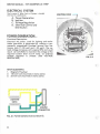
POWER GENERATION
Functional Description:
Electrical AC power, used for lighting and tachometer operation is generated by rotating a permanently magnetized flywheel around two stationary coi Is ( 1-120 watt and 1-23 watt). The noload voltage increases with engine RPM and could
reach 32 volts RMS. To maintain the voltage at the
required system level (13-14 volts). an external
voltage regulator is utilized, (See VOLTAGE
REGULATION)
MAIN ELEMENTS:
1.
2.
3.
Magnetic Flywheel
120 watt coil (mounted on stator plate)
23 watt coil (mounted on stator plate)
// L // ~ //
/
~
LIGHTING
COILS
~
I
I
FIG. 3-1 POWER GENERATION SCHEMATk
3·2
...•
FIG. 3-2
SERVICE MANUAL· 1975 SCORPION LIL' WHIP
IGNITION
Functional Description:
(See SCHEMATIC FIG. 3-7) .
Rockwell engines are equipped with a flywheel
magneto type ignition. An electrical current is
generated by rotating a permanently magnetized
flywhee l about the ignition coi l. The current
initiated in this coil in turn energizes the primary
coils of the external ignition coils. The secondary
coils of the externa l ignition coils are situated in
the force field generated by the primary coils.
When the points close, causing an interruption of
the current flow through the primary winding, its
force field immediately collapses and generates a
very high voltage in the second coil. This voltage in the
region of several thousand volts will jump the spark
plug gap causing ignition to begin.
r--ENGINE
CONNECTOR
The collapsing lines of force cut through the primary
windings, raising the voltage in that circuit also.
As this occurs, the condenser absorbs the generated current to reduce the tendency to overload
the points. As soon as the voltage level in the
primary winding drops below that of the condenser ,
current again flows in the origina l direction,
energizing the system. This occurrence and the r eversal happens severa l times each cycle cr eating a
powerful, long duration spark for more re liabl e
ignition.
FIG. 3-4
MAIN ELEMENTS:
1.
2.
3.
4.
5.
Ignition Coil (Stator)
Condensers (2)
Breaker Points (2)
Ignition Coils (External) (2)
Spark Plugs (2)
FIG. 3-5
3-3
SERVICE MANUAL - 1975 SCORPION LIL' WHIP
{STATOR)
·SEE ENGINE DISASSEMBLY
(SECTION l) FOR FLYWHEEL
AND STATOR REMOVAL
FIG. 3-6
CONDENSER
Hlo
~SPARK
PLUG
EXTERNAL IGNITION COILS
t
.T.
SPARK PLUG
-FIG. 3-7 IGNITION SCHEMATIC
ENGINE CONNECTOR
3-4
SERVICE MANUAL· 1975 SCORPION LIL' WHIP
- - STATOR IGNITION COIL TO
EXTERNAL COIL CONNECTORS
I
J
FIG. 3-8
EXTERNAL COIL
l
COIL TO SPARK PLUG LEAD
EXTERNAL COIL
GROUND
FIG. 3-9
3-5
SERVICE MANUAL - 1975 SCORPION LIL' WHIP
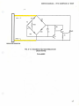
VOLTAGE REGULATION
Functional Description:
The voltage regulator is connected across the
lighting coils in parallel with the electrical load
of the sled. (See SCHEMATIC- ELECTRICAL DISTRIBU TION AND CONTROL - FIG. 3-16). Under operating
conditions, the voltage drop across the regulator is
such that approximately 13.8 V RMS is supplied to
the snowmobile lighting circuit.
NORMAL LIGHTING COIL VOLTAGE
ALTERATION OF VOLT AGE
WAVE WHEN SCR
CONDUCTS
Scorpion PIN 043299
, (See FIGs. 3 -10, 3-11 and 3-12).
MAIN ELEMENTS:
1.
2.
3.
4.
5. ·
TIME
FIG. 3-10
Si Iicon Control Rectifier (SCR)
Resisto~s (R 1, R2, R3, R4, Trim)
Conden"ser (C 1)
Diodes (CR 1, CR2, CR3, CR4)
Transistors (Z 1,_Q 1)
This solid state regulator is also a shunt type regula tor. When the magneto output drops below the
specified pre-set regulator voltage level, the regula , tor drqps out of the system, providing maximum
avail.able voltage to t~e load at decreased speeds.
In the first half of the operating cycle when line 1 is
positive with respect to line 2, C1 will charge
through CR1, C1, R2 and CR2 until the voltage drop
across C 1 reaches the level necessary to cause Z 1
to conduct. At this point, Q1 will draw base current
and then pass current through CR 1, the emitter col lector of Q1 and into the gate of SCR. SCR is "turned
on" and shunts the output of the magneto.
(
VOLT AGE REGULA TOR •
043299
FIG. 3-11
In the second half cycle the shunting mechanism of
the regulator is not operative.
If there is a sufficiently heavy load on the magneto
during the first half cycle, the load effectively holds
the voltage output to a value less than that required
to turn the SCR on and therefore full output goes to
the load.
)
3-6
SERVICE MANUAL· 1975 SCORPIO N LIL' WHIP
• ell
LINEl__J
Cl
SCR
LINE2-.,
I Z7 /I// L //I/ 7Z / 7 / Z III.~----------------------~------~
REGULATOR CONNECTOR
FIG. 3·12 MAGNETO VOLT AGE REGULATOR
(SOLID STATE)
P/N 043299
I
3-7
SERVICE MANUAL - 197 5 SCORPION LIL' WHIP
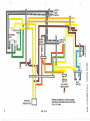
ELECTRICAL CONTROL
AND DISTRIBUTION
Functional Description
Power is supplied ·continuously to the brake
light switch, so that any time power is being
ge ne rated, th e brake light will go on if the brake
is ap p lied.
Powe r to all the other items is supplied through the
ignition switch in the "LIGHTS" mode.
HEADLIGHT HARNESS CONNECTOR
IGNITION SWITCH
CONN
V OLT AGE REGULATOR
CONNECTOR---.
Grounding of the System is accomplished at three
locations:
1.
2.
3.
To the chassis at the rear end
To th e cha ssi s from wire harness
at eng. connector.
To the stator plate on the engine
MAIN ELEMENTS:
1.
2.
3.
4.
5.
6.
7.
8.
Main Wiring Harness
Seat Wiring Harness
Taillight Wiring
Harness
Safety Stop Switch
Bre ak Light Switch
Hi -Lo Switch
Ignition Switch
Headlight Harness
)
HI-LO 'SWITCH
CONNECTOR ,...,.----~'
BRAKE LIGHT
SWITCH
CONNECTOR
SAFETY STOP
SWITCH/HARNESS _ _ _ _.....,..,.,
E CONNECTOR
FIG. 3-13
. : - --
-
- - - - H I-LO SWITCH/HARNESS
BRAKE LIGHT
SWITCH/HARNESS
FIG. 3-14
3-8
SAFETY
STOP
I SWITCH
•
-~~-·=1·
I
IGNITION
COIL
IGNITION
...._SWITCH
::z:::
m
)>
c
,...
a:t
-f
"'m:;a
s
n
m
3:
)>
z
c:
TAILLIGHTS
BRAKE LIGHT
I
I
/1
w
.0
)>
r-
-.....
'
. .0
en
"'n0
.,
I
VOLTAGE
REGULATOR
HI-LO
SWITCH
:;a
D
WIRING SCHEMATIC (COLOR CODED)
ELECTRICAL DISTRIBUTION & CONTRO L
1975 LIL' WHIP
0
z
r-
r:
~
FIG. 3-15
.,:::J:
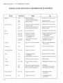
SERVICE MANUAL - 1975 SCORPION LIL' WHIP
WIRING CODE (ELECTRICAL DISTRIBUTION &CONTROL)
i
COLOR
FUNCTION
TO
FROM
Eng. Connector
(Engine Ignition Coil)
Safety Switch Connector
Brake Switch
Safety Switch Connector
Safety Switch Connector
Hot
Hot
Engine Connector (Engine
Ignition Coil
Safety Switch Connector
Brake Switch Connector
Blue
Hot (Hi)
Hi-Lo Switch (Hi)
Headlight Connector (Hi)
Brown
Ground
Ground
Engine Connector
Engine Connector
Ground
Voltage Regulator
Connector
Chassis (Roll Bar Bracket)
Voltage Regulator
Connector
Instrument Connector
Ground
Ground
Instrument Connector
Taillight
Headlight Connector
Chassis (Tunnel)
Black
Hot
Hot
Hot
Black/White
Hot
Ignition Switch
Brake Switch Connector
Ignition Switch Connector
Brake Switch
Green
Hot
Ignition Switch Connector
El ectric Start (Regulator
Connector)
Orange
Hot
Engine Connector
Instrument Connector
Orange/Black
Ground
Engine Connector
Instrum e nt Connector
Red
Hot
Brake Switch Connector
Hot
Voltage Regulator
Connector
Brake Switch Connector
Tan
Hot
Brake Switch Connector
Brake Lights
White
Hot (LO)
Hi-Lo Switch Connector
(Lo)
Headlight Connector (Lo)
Yellow
Hot
Hot
Hot
Ignition Switch Connector
Ignition Switch Connector
Hi-Lo Switch Connector
Taillights
Hi-Lo Switch Connector
Instrument Connector
Yellow/Black
Ground
Engine Connector
Voltage Regulator
Connector
Yellow/Red
Hot
Engine Connector
Voltage Regulator
Connector
3-10
Ignition Switch Connector
)
SERVICE MANUAL· 1975 SCORPION LIL' WHIP
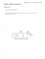
SPECIAL TESTING - ELECTRICAL
(
Regulator Tests
1.
Set point check (P /N 043299)
Use test circuit as shown below. Read vo ltage across regulator. Value should be
approximately 13.8 volts.
(
lOOW
s...n..
120V
REGULATOR SET POINT TEST CIRCUIT
3 - 11
SERVICE MANUAL · 1975 SCORPION LIL' WHIP
TROUBLE SHOOTING (ELECTRICAL)
)
TROUBLE
PROBABLE CAUSE
REMEDY
Open Circuit:
Faulty Switch(s)
Separated Connector(s)
Cut Wiring
Repair or replace faulty
or damaged element.
Wiring shorted to ground:
Damaged Insulation
Repair or replace damaged
or faulty element.
Faulty Regulator (Shorted SCR)
Replace regulator.
Shorted or open lighting coil.
Replace armature plate.
Faulty regulator- Incorrect
regulator set point (too low).
Replace regulator.
Faulty regulator -Incorrect Set
Point (too high).
Replace regulator and failed
bulbs.
Burned out
lights (individual)
Failed bulb.
Replace bulb.
Burned out lights
Intermittent short in wire harness.
Repair or replace wire harness.
Engine won't run
1. Open or shorted windings in
1. Replace armature plate.
Weak or no
spark
ignition coils (stator).
2. Open or shorted windings.
in external ignition coil.
3. Shorted condenser - dirty or
worn.
4. Damaged (burned) points.
No lights
Dim lights
Burned out
lights (all)
)
Engine won't runAdequate spark.
l. Burned or fouled plugs.
3-12
3. Replace condenser.
4. Replace points.
l. Replace plugs. Determine that
correct plugs are being used.
CHECK ENGINE TROUBLE
SHOOTING .
2. See Engine Trouble Shooting
Section
Unacceptable
Engine Performance
2. Replace external coil.
See Engine Trouble Shooting
Section
1975
Scorpion
Lil' Whip
Service Manual
Clutch/Drive
Section
4-1
SERVICE MANUAL- 1975 SCORPION LIL' WHIP
DRIVE SYSTEM
Functional Description:
The main elements included in this system are:
1. Drive Clutch
2. Drive Belt
3. Driven Clutch
4. Chain Case with sprockets, chain and chain tensioners.
5. Drive shaft with track drive sprockets.
The power from the engine is transmitted through this system to the track in
sequence of elements listed above to propel the machine.
The drive clutch, belt and driven clutch serve as a torque converter. The torque
converter on the snowmobile "down shifts" to a lower ratio as the track load increases as readily as it "up shifts" when the track load decreases.
To accomplish the automatic shifting, the movable sheave of the driven clutch
is fitted with a helical ramp which is guided by a follower. This sheave is controlled by a spring pre-stressed in torsion and compression to hold the sheaves
tog ether at the maximum pitch diameter.
Under acceleration, the torque from the engine is greater than the demand
from the track. The drive clutch then closes, forcing the belt outward between
the sheaves. Belt tension and wedging action .is unbalanced at the driven clutch
and the sheave faces are wedged open against the helical cam. This action
winds up and compresses the spring.
Under steady running, all forces are balanced and the belt chooses a ratio at
which this balance exists.
Under deceleration, the driven sheave is stalled slightly, which unbalances the
forces so that the sheave is forced to a new larger pitch diameter. Belt tension
is thus increased, the wedging action opens drive sheave and a new lower
pitch diameter is chosen to again bring all forces to balance.
4-2
SERVICE MANUAL - 1975 SCORPION LIL' WHIP
DRIVE CLUTCH DISASSEMBLY
1. Open hood and ·clutch guard.
FIG 4-1
2. Remove clutch attaching bolt and bell retaining bolt. Use impact wrench capable
of 75 or more ft. lbs. torque {In the field
alternate method may be used.) Making
sure ignition is off, run engine up on
compression using %" socket and
ratchet. Strike ratchet with plastic or
rubber mallet. {See Figure 4-2).
FIG 4-2
3. Remove bell housing (See Figure 4 -3.)
FIG. 4-3
4-3
SERVICE MANUAL - 1975 SCORPION LIL' WHIP
4
Movable sheave should slide off spline
eas ily. Next remove spring and retainer.
(See Figure 4-4.)
FIG 4-4
5. Remove snap ring retainer and idler bearing
if necessary. {See Figures 4 -5 and 4 -6.)
FIG. 4-5
FIG. 4-6
4-4
SERVICE MANUAL- 1975 SCORPION LIL' WHIP
(
6. If necessary to remove stationary sheave, insert p lug (2 13/16" long x 3/4" diameter) in
stationary center hole and re-insert be ll
retainer bolt. Tightening bell bolt will force
stationary off crankshaft. (See Figure 4-7.)
FIG. 4-7
(
7. Removing torque plug retainer will allow
torque plug to be r emoved and in spected.
(See Figure 4-8.)
FIG. 4-8
4 -5
SERVICE MANUAL · 1975 SCORPION LIL' WHIP
8. Detaching springs and weight arm retainers
will allow weight arms to be removed. (See
Figures 4-9,4-10, 4-11.)
DRIVE CLUTCH INSPECTION
FIG. 4-9
Inspect weight arm bushings and rollers for
cracks and flat spots. Also check snap rings on
weight arm shaft ends.
Inspect torque plug for fit and wear. (Should have
no more than .020" space between torque plug
and casting.)
Inspect idler bearing for freedom of rollers and
retention of lubricant.
FIG. 4-10
Inspect snap ring groove on stationary and spring
retainer for wear.
Inspect bell housing for cracks, particularly in
center area near spline.
FIG. 4-11
4·6
SERVICE MANUAL- 1975 SCORPION LIL' WHIP
(
RE-ASSEMBLY OF DRIVE CLUTCH
CAUTION:
If stationary has been removed,
assure that there is no grease on
either the shaft or sheave before reassembly.
Re-install idler bearing, snap ring, retainer
and spring. Place weight arms on movable
sheave (after checking them for lubrication).
Attach retainers, checking to see that the
small locating hole in the bearing aligns with
th e detent on inner face of retainer. Install
torque plug and torque plug retainer. Install
bell housing, checking alignment with stub
on torque plug provided for this purpose.
Place spring washer and bell retainer bolt on
next, assuring that the bolt has bottomed out
secure ly in proper alignment. Install clutch
attaching bolt. Torque on both bolts to 50 ft.
lbs.
FIG. 4-12
FIG. 4-13
FIG. 4-14
4 -7
SERVICE MANUAL - 1975 SCORPION LIL' WHIP
DRIVEN CLUTCH DISASSEMBLY
1.
Remove chain case cover.
2. Remove chain tension ers , unbolt and remove
top sp rocket and chain.
DRIVEN SHAFT ----.....;.;;
LOCKING BOLT
C H A I N - - - - - -- CHAIN TENSIONER ,- - - BOTTOM SPROCKET-- -
4-8
SERVICE MANUAL - 1975 SCORPION LIL' WHIP
)
3. Remove driven unit from chaincase (tapping
shaft lightly with plastic mallet). Remove
snap ring and wash er from cam top and slide
off shaft. (See Figures 4-16, 4-17, 4-18).
CAM TOP
CAM BOTTOM
FIG. 4-16
FIG. 4-17
FIG. 4-18
4-9
SERVICE MANUAL· 1975 SCORPION LIL' WHIP
4. Remove key and main spring. (See Figure 4-
19).
KEYWAY
KEY
FIG. 4-19
5. This should allow cam bottom and movable
sheave to be removed as a unit (See Figure
4-20), and disassembled if necessary. (See
Figure 4-21.)
FIG. 4-20
FIG. 4-21
4-10
SERVICE MANUAL- 1975 SCORPION LIL' WHIP
6. Stationary sheave may then be unbolted
from clutch shaft (See Figures 4-22 and
4-23) and bearings can be pressed off
if necessary.
ST A TIONARV SHEAVE
CLUTCH SHAFT
FIG. 4-22
FIG. 4-23
4 - 11
SERVICE MANUAL · 1975 SCORPION LIL' WHIP
I
l
DRIVEN CLUTCH INSPECTION
Inspect snap ring groove for wear.
Inspect Helical ramps for wear and breakage.
(See Fig. 4-16).
Inspect bronze bushing in cam bottom for any
signs of looseness or slippage (should be staked
in solidly).
Rotate and check bearings visually.
Inspect sheaves for cracks particularly around
bolt holes.
Check splines and threads on sprocket side of
main shaft for wear, crossthreading, etc.
RE-ASSEMBL V OF DRIVEN CLUTCH
Attach stationary sheave to clutch shaft. Assemble cam bottom and movable, then place on shaft
followed by the woodruff key and main spring.
Place cam top on shaft, preloading spring 1/3 turn
and install washer and snap ring.
Upon replacing the driven clutch in chaincase,
check to assure that the 0 -ring in chaincase bore
is intact and in good condition. Also check 0-ring
in chaincase cover before installation.
4·12
SERVICE MANUAL - 1975 SCORPION LIL' WHIP
DRIVE BELT SPECIFICATIONS
(
t
Drive belt width
Drive belt outside diameter
inches.
1 1/8 - 1 3/16 inches
43 1/8 - 43 1I 4
Clutch offset (Drive to Driven) - 3/8 inch
Center to center distance- 10 1/2 inches
(Drive clutch to Driven clutch)
CLUTCH ALIGNMENT BAR---""""!""""--"
(FOR 3/8" OFFSET)
DRIVEN CLUTCH====
FIG. 4-24
)
4 -13
SERVICE MANUAL · 1975 SCORPION LIL' WHIP
CHAIN CASE DISASSEMBLY
r
Remove brake cable at chain case end. Remove
cover, tensioners, upper and lower bolts. Remove
sprockets with chain. Remove bearing flange bolts
and brake cable. Taking care to check number of
shims between the chaincase and the tunnel and
their specific locations, remove the chaincase from
the tunnel. When the chaincase is reassembled to
tunnel, assure that the spacers go back where they
were. Before tightening case to tunnel be sure to
adjust case to achieve correct center distance of
10 V2" between center of driven and drive clutches.
Reverse procedure to install.
REMOVAL OF FRONT DRIVE SHAFT
Remove brake cable at chain case end. Remove
chaincase cover, tensioners, lower sprocket and
chain. Loosen locking collars on front drive
bearings (see Fig. 4-25). Remove speedometer,
drive adaptor and flanges. Slide drive shaft
through chaincase mounting hole until right side
clears main frame and remove. (It is necessary to
detach forward end of pararail to gain clearance
for entire removal of front drive shaft - See Suspension Section.)
REMOVAL OF FRONT DRIVE SPROCKET
Punch out spiro I pins (see Fig. 4-25, 4-26). Then
taking care to see that the shaft is clean, slide
sprockets off. To reassemble, reverse procedure.
LOCKING COLLARS
SPIROL PIN
4-14
FIG. 4-25
SERVICE MANUAL- 1975 SCORPION LIL' WHIP
(
\
SPIROL PIN
r
BEARIN
BRG. FLANGES
Inspection of Drive Shaft
0-RING
FIG. 4-27
Observe shaft for signs of stress, cracks and bending, check bearings and collars for breakage.
Check sprockets for loosening of pin holes.
NOTE : Small cracks in the white material of the
drive sprocket are not signs of failure, but a result
:>f ~hrinkage during manufacture.
4-15
SERVICE MANUAL- 1975 SCORPION LIL' WHIP
TROUBLE SHOOTING
The opera tin g diameter of the drive and driven
clutch governs the ratio of red uction or ad vantage in the snowmobile drive train. Therefore,
to gain maximum performance and economy,
these areas cannot be overlooked.
The following are some symptoms, causes and
cures to aid in troubl e shooting the clutch/
drive sy stem.
Engine Overs peed:
Excessi v e
vibration of
drive train:
Excessive noise
from front drive
sy stem:
4-16
REMEDY
CAUSE
TROUBLE
Drive clutch may not be closing fully. This can
be checked by drawing a lin e on th e face of
th e sheave (d rive or driven) with a crayon
from the center outward. Then running the
machine at top speed will tell you how far
th e clutch clos ed by erasu re of the line by the
belt.
Disassemble clutches
examine and replace
malfunctioning parts.
If the clutch is closing fully, the belt may be
wrong length or the cen t er to cen t er distance
of the clutches may be off. Finally, check the
number of teeth on upper and lower
sprockets.
Replace belt. Correct
center to center distance (see belt specs.)
Replace
incorrect
sprocket.
Tachometer
(hi gh)
incorrectly
Replace tach.
Belt may be worn and too narrow to achieve
correct ratio (see belt specs).
Replace belt.
may
be
reading
Track may be too loose allowing sprock e ts to
slip over drive lug s or "rat ch et ".
Correct track tension.
Chain may
sprockets.
Check and
replace
broken
or
weak
chain tensioners.
be
slipping
over
teeth
on
Malfunction of front drive b eari ngs.
Replace bearings.
Chain case may be dry of oil.
Disassemble
and
check - chain, sprockets and chain case
cover seal (0 ring) replace worn parts and
reassemble.
Refill
with oil check level
and check for leaks.
J
)
1975
Scorpion
Lil' Whip
)
Service Manual
Suspension
Section
5-1
SERVICE MANUAL · 1975 SCORPION LIL' WHIP
FUNCTIONAL DESCRIPTION:
(
The four main elements of a snowmobile suspension are:
1.
2.
3.
4.
Skis
Track Suspension
Seat
Operator
All elements work together to perform the sus pension functions to the optimum degree.
The suspensions are basically designed to:
1.
2.
3.
4.
Protect the operator from physical abuse or
injury.
Keep the operator from being ejected from
his operating position and controls.
Prevent damage to the machine.
Increase ground contact and improve traction.
On the 1975 Lil' Whip, the track suspension
(trailing arm bogey) is a multiple type suspension unit which simply means that it has five
(5) separate components. It also possesses the
advantage of being able to traverse marginal
snow conditions without damaging effects to the
suspension system.
5-2
SERVICE MANUAL - 1975 SCORPION LIL' WHIP
)
2
21
(
23
20
FIG. 5-1
21
NOTE: All identifying numbers in subsequent explanation
and in·struction s refer to the numbers on thi s page.
5-3
SERVICE MANUAL - 1975 SCORPION LIL' WHIP
SUSPENSION SYSTEM - REMOVAL,
(
DISASSEMBLV, ASSEMBL V
(A) REMOVAL
1.
Raise and block vehicle off the ground.
Loosen th e two (2) sliding nuts #17.
TENSION
PIVOT
BOLT
SLIDING
NUTS
FIG. 5-2
2.
Remove the two (2) bolts #6 from the draw
blocks #7 . This will relieve the track tension
and permit easy removal of the bogey units.
)
DRAW BLOCKS
FIG. 5-3
)
5-4
SERVICE MANUAL - 1975 SCORPION lll' WHIP
3.
Remove the two (2) bolts #19 that anchor
the rear bogey unit to the tunnel. Shove
forward on the bogey unit to release the
two spring tangs from the tunnel. Remove
the remaining three units in the same manmanner.
FIG. 5-4
Note:
For ease of accessibility, always work from
rear toward the front when removing or installing.
FIG. 5-5
FIG. 5-6
5-5
SERVICE MANUAL - 1975 SCORPION LIL' WHIP
(B) DISASSEMBLY
1.
Rear end
Release the two (2) springs #12 from tunnel. Note
which notch springs are inserted in. Remove sliding
nuts #17 and washer #3. Remove the two (2) draw
blocks #7. Remove the two (2) bolts #5, washers #16
and lock washers #4.
Remove the four bolts #18 and rear end is disassembled and ready for complete removal.
REAR IDLER SP
2.
Bogey Springs #20
FIG. 5-7
(Two Wheel Weldments #26)
Unwrap the spring anchor from the spring tang in the
two bogey weldments to remove springs from the
bogey weldments #26.
1
FIG. 5-8
5-6
LsPRING ANCHOR....__ __.
FIG. 5-9
SERVICE MANUAL - 1975 SCORPION LIL' WHIP
(Three Wheel Weldments #23)
(
The spring anchor must be pried up to
release the spring tangs on the three (3)
bogey weldments #23.
r--- -sPRING ANCHOR---;
NOTE: Push spring toward center of
weldment to remove.
CAUTION: When installing the springs
on the three (3) bogey weldments, make
certain that the anchors are peened
down as close to the weldment as
possible. If this is not done, track
damage could occur. (FIG. 5-1 0).
FIG. 5-10
(C) ASSEMBLY
Reverse procedure for disassembly can be used.
However, the bogey weldments can be installed
easier by installing the rear springs #12 in their
respective notch in the tunnel and by installing
the draw blocks #7 after the installation of the
four (4) bogey weldments.
(
TORQUE REQUIREMENTS FOR ASSEMBLY ARE:
ITEMS
TORQUE
17
15- 19 Ft. Lbs.
18
45Ft. Lbs.
19
15-19 Ft. Lbs.
5
15-19 Ft. Lbs.
)
5-7
SERVICE MANUAL • 1975 SCORPION LIL' WHIP
'
SPECIAL ADJUSTMENTS
REAR IDLER SUSPENSION ADJUSTMENT
The rear idler spring adjustment governs preload and
should be correlated with the weight of the rider normally
using the machine.
Too much spring tension will result in a harsh ride and increases the weight carried on the skis, thus increasing
steering effort.
Too little spring tension will result in the bottoming out of
the suspension. A harsh ride and shortened life to the
suspension components will occur.
1.
Proper spring tension is a function of operator weight
and preference. Therefore, the correct setting can
only be determined by a trial ride.
2.
To adjust, move spring tang to desired slot, making
certain that each spring is tightened or loosened the
same amount. Check track alignment after chang ing
spring setting. (FIG. 5-11).
3.
Evaluation by the rider may require further adjustment to obtain the desired riding qualities.
ADJUSTMENT
NOTCHES
/;.
FIG. 5-11
/
5-8
SERVICE MANUAL - 1975 SCORPION LIL' WHIP
TRAILING ARM BOGEY SUSPENSION:
TRACK TENSION
Proper track tension is extremely important to assure
long life of all associated components and efficiency
of the track drive system.
The track tension should be checked at the following
intervals:
1.
When the machine is new (dealer preparation).
2.
After the first hour and 10 hours.
3.
Every 30 days, or 200 miles of operation.
4.
At the start of each snow season.
5.
Upon hearing track sprocket ratcheting. Ratcheting is most noticeable under hard acceleration or
a braking condition. (Ratcheting is best explained
as a harsh grinding or thumping noise.)
TRACK JACKS
FIG. 5-12
5·9
SERVICE MANUAL - 1975 SCORPION LIL' WHIP
The following procedure applies to the trailing arm
bogey equipped Scorpion Li/' Whip:
1.
The track should be at room temperature or
should have been recently run to remove any stiffness, caused by cold weather.
2.
Elevate the rear of the machine.
3.
Adjust each "Track Jack" to one inch (1 ").
4.
Insert both "Track Jacks" between the track and
both bogey whee ls as shown in Fig. 5-1 2.
5.
If the track is properly tensioned, the green ring
should be just visible or aligned with the lip of the
cylinder. Adjustment is required if the green ring
is not visible, or is above the lip of the cylinder.
6.
To make adjustment, loosen the two tension pivot
bolts and the two sliding nuts (See Fig. 5-2).
Either tighten or loosen the adjustment bolts until
proper adjustment is measured on both "Track
Jacks" (green ring aligned with lip on cylinder).
7.
Retighten the sliding nuts as well as the tension
pivot bolts.
NOTE: "TRACK JACKS" are available at Scorpion, Inc.
It is an accessory item, Part #90 1736.
5- 10