1
•'
;
.:·· j '\.,
~·
.~:
!'·
<
~
:
..
l'
. ·j
I
1976
.'
I
Scorpion
Range Whip
l
1
I
.i
I;
··I
I
l
I
Service Manual
Engine Section ·
.
.
..
.
'
1
1- 1
l
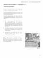
SERVICE MANUAL· 1976 SCORPION RANGE WHIP
ENGINE SYSTEM
Functional Description:
2-CVCLE ENGINE FUNDAMENTALS
The Cuyuna 2-cycle air-cooled gasoline engine,
particularly the axial fan-cooled twin cylinder
engine, has become very popular today for
snowmobiles. It is uniquely qualified for this application because of its high power output, light
weight and ease of lubrication, with fewer
moving parts than other conventional 2-cycle
and 4-cycle engines.
However, in order to get the best possible use
and ensure that it retains its high degree of
dependability and endurance, it must receive
proper care and maintenance. Therefore, it is
necessary for us to know something about the
basic fundamentals of this engine and how it
functions.
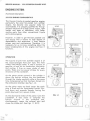
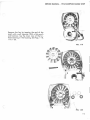
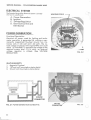
OPERATION
The Cuyuna 2-cycle Twin Cylinder engine is of
the loop-scavenged third port type, the most
widely used design today. It uses a mixture of
gasoline, oil and air for combustion, lubrication
and cooling. It fires on every stroke of each
piston. There are two power strokes for every
revolution of the crankshaft.
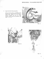
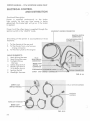
EXH/UST
As the piston moves upward in the cylinder it
draws the fuel/air mixture into the crankcase
through the intake manifold while at the same
time compressing fuel that has been forced into
the combustion chamber. See Fig. 1-1 A.
TRANSFER
As the piston nears top dead center the spark
plug is fired and the compressed fuel/air mixture burns and expands thereby forcing the
piston downward on a power stroke.
As the downward stroke of the piston turns the
crankshaft, it also starts to compress the
fuel/air
mixture
in
the
crankcase
and,
simultaneously, opens the exhaust port and
closes the intake port. See Figs. 1-1 B & C.
l-2
•'
FIG. 1-1
SERVICE MANUAL- 1976 SCORPION RANGE WHIP
After the exhaust port is fully open and the intake port is fully closed, further piston travel
starts to open the transfer ports. The com pressed fuel/air mixture from the crankcase
then travels up the transfer ports and into the
combustion area.
After most of the burned exhaust gases have
left the cylinder, an incoming charge of fuel/air
mixture scavenges the combustion area giving it
a fresh charge and the cycle i s then repeated.
See Fig. l -1 D.
Because lubrication is dependent on the m1xmg
of oil and fue l, it is extreme ly important that
good quality oil and gasoline are properly
mixed. The proper ratio of oil to gasoline will
prevent possible engine overheating, piston or
cylinder scoring, or eventua l engine seizure.
Too much oil and not enough gasoline can lead
to incomplete combustion, fouled plugs, carbon
build-up and muff ler clogging.
l -3
SERVICE MANUAL. 1976 SCORPION RANGE WHIP
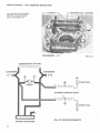
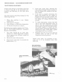
EXHAUST SYSTEMS
SELECTION
Selection of an exhaust system (including
exhaust manifold, intermediate pipes, elbows
and muffler), is a result of thorough test
procedures involving measurement of fuel consumption, horsepower and noise level. Contrary
to popular belief, the exhaust system is not only
for quieting the engine, but also serves to increase horsepower output. Changes made to the
original equipment exhaus t system by changing
any component in the system can result in loss of
power and/or severe engine damage. For these
reasons, intermediate lengths of pipe betweeen
the cylinder and the muffler are particularly
cr itical.
Donaldson
TUNED MUFFLERS
FIG. 1-2
Tuned mufflers allow the engine to exhaust its
spent charge into an adequate volume and
properly matched muffling sys t em. More im portant, the mufflers that are tuned, incorporate
designs that suck th e exhaust gas from the cylinder allowing f uel and air to rapidly replace it and
also "cram" over-scavenged fuel and air mixture
from the exhaust pipe back into the cy linder
using sound waves and sound energy. Th is is accomplished at the speed of sound which allows
the engine to produce higher torque at higher
RPMs.
Tuning
Co urt es y o f Do nald so n Muffl e r Co
FIG. 1-3
l-4
SERVICE MANUAL· 1976 SCORPION RANGE WHIP ·
HOW TUNING WORKS
The megaphone effect of the expanded intake
tube scavenges exhaust gas from the cylinder
allowing rapid replacement of the fuel/air mixture from the crankcase. Reflected sound waves
and sound energy stop over-scavenging and
return fuel/a i r mixture to the cylinder. It gives a
supercharging effect even though it operates
from the exhaust rather than the intake side.
Over-scavenging is also retarded by moderate
muffler back pressure. Silencing is accomplished
after power is maximized by acoustical packing in
the resonator outlet tube plus chambering and
baff ling which gives an effective 2-pass muffler
design.
)
. l -5
SERVICE MANUAL- 1976 SCORPION RANGE WHIP
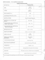
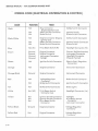
TABLE OF SPECIFICATIONS
DESCRIPTION
BORE
STROKE
ENGINE MODEL
CUYUNA400
2.559"
( 65.0mm)
398
COMPRESSION RATION (actual)
12:1
LIGHTING COIL VOLTAGE AND
OUTPUT
Bosch Flywheel Magneto
12V 150W
*TIMING BEFORE TDC (CENTRIFUGAL
WEIGHT ADVANCED)
.102-.112
TIMING BEFORE TDC (CENTRIFUGAL
WEIGHT RETARDED)
.0 18" to .020"
BREAKER POINT GAP
.014" to .016"
SPARK PLUG THREAD
14mm. x 1.25- 3/4" reach
SPARK PLUG GAP
SPARK PLUG (ORIGINAL
EQUIPMENT)
TYPE OF ENGINE COOLING
ROTATION OF CRANKSHAFT
CARBURETOR
FUEL/OIL RATIO
GASOLINE
-.
.020"
(0.5mm.)
CHAMPION
N-3
Axial Flow Fan
Counterclockwise (PTO side)
Walbro W F
As Specified on Scorpion Oii Container
95 octane, minimum (lead free not acceptable)
..
TYPE OF OIL
Special 2-Cycle Snowmobile Oil
* Do not exceed indicated advance, as this will result in severe engine damage.
l-6
.... .
2.362"
(60mm)
DISPLACEMENT IN cc
IGNITION SYSTEM
.-f
~~:
' .
SERVICE MANUAL· 1976 SCORPION RANGE WHIP
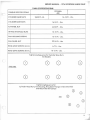
TABLE OF SPECIFICATIONS
CUYUNA
400
TORQUE SPECIFICATIONS
CYLINDER HEAD NUTS
16-18Ft.-Lbs.
28-32 Ft.-Lb.
CYLINDER BASE NUTS
16-1 8 Ft. - Lbs.
FLYWHEEL NUT
44-50 Ft. - l:bs.
INTAKE MANIFOLD NUTS
16- 18 Ft. - Lbs.
FAN HOUSING SCREWS
16-1 8 Ft. - Lbs.
FAN WHEEL NUT
22-24 Ft.- Lbs.
RING GEAR SCREWS (6mm.)
6-7Ft.- Lbs.
RING GEAR SCREWS (8mm.)
10-12Ft.- Lbs.
Tightening Sequence for Cylinder Base Nuts
All Models
(_
PTO SIDE
8
0
8
0
0
0
0
8
Tightening Sequence for:
Cylinder Head Nuts, Fan Housing, Ring Gear Flange, Intake Manifold
and Recoil Starter Clamps
0
400
0
0
.
0
r
0
CD
'
1-7
SERVICE MANUAL · 1976 SCORPION RANGE WHIP
CUYUNA TWIN CYLINDER ENGINES
CUYUNA .400
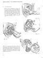
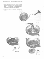
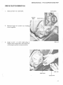
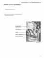
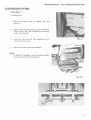
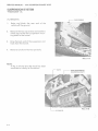
DISASSEMBLY
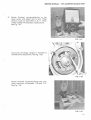
A.
Recoil Starter
Remove four (4) screws holding the
recoil assembly to the fan housing.
See Fig. 1-4.
See pages 1-28 A, B, C for recoil starter
disassembly.
B.
Lower Fan Pulley and Carrier Assembly
FIG. 1-4
FIG. 1-5
Remove the three (3) hex head bolts on
the carrier. Remove carrier, lower pulley
assembly and V -belt. See Figs. 1-5, 1-6.
C)
FIG. 1-6
l-8
SERVICE MANUAL· 1976 SCORPION RANGE WHIP
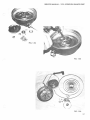
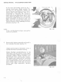
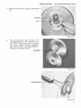
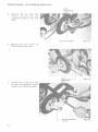
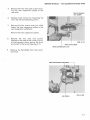
C.
Upper Fan Belt Pulley Assembly.
Insert a 3/16" drill or a suitable punch
through the indexing hole into the im -·
peller body. With a 17 mm socket
wrench, remove the fan nut, lock
washer, pulley halves and spacers. See
Figs.1-7, 1-8,1 -9.
FIG. 1-7
FIG. 1·8
FIG. 1·9
1-9
SERVICE MANUAL· 1976 SCORPION RANGE WHIP
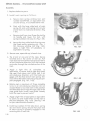
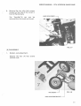
D.
()
Flywheel Magneto
Remove the crankshaft nut using a 27
mm socket wrench. Pull the flywheel by
attaching flywheel puller 444-31-843-2 to
the flywheel flange using bolts provided.
Screw the three bolts through the puller
into the flange and tighten evenly. With
a socket wrench, tighten the puller bolt
until the flywheel loosens on the
crankshaft. See Figs. 1-10, 1-11, 1- 12, 113.
FIG. 1-10
0
FIG. 1-11
FIG. 1-12
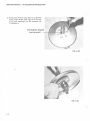
NOTE: It is important that care be taken in
removing the flywheel assembly because the
positioning key located in the keyway may
stay in its original position and thereby cause
damage to the advance mechanism. A small
icepick or screwdriver may be used to loosen
and remove the key.
()
FIG. 1-13
l -10
SERVICE MANUAL· 1976 SCORPION RANGE WHIP
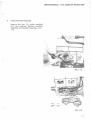
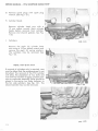
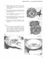
E.
Intake Manifold Assembly
Remove the four (4) intake manifold
nuts and washers. Remove manifold
assembly and insulators. See Figs. 1-14,
1-15.
•'
(
---
FIG. 1-14
~~
·· ·~·;t'
oo
00
FIG. 1-15
l -1 l
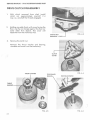
SERVICE MANUAL· 1976 SCORPION RANGE WHIP
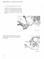
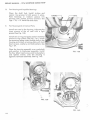
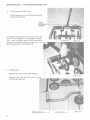
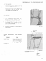
F.
Fan Housing and Armature Plate Assembly
Remove screw holding spark plug wire
bracket to fan housing. With a socket type 5
mm Allen wrench and impact driver, remove
the four (4) mounting bolts holding fan
housing to crankcase. (See Fig. 1-16).
Remove fan housing from crankcase (See
Fig.1-17).
FIG. 1-16
Unplug connector housing coil wires. (Note
color coding of wires.) Remove armature
plate assembly and wires, as a unit, from
fan housing.
FIG. 1-17
1- 12
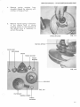
SERVICE MANUAL· 1976 SCORPION RANGE WHIP
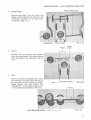
Remove the fan by tapping the end of fan
shaft with a soft hammer. With a flat punch
and hammer, tap the inner race of th e furthest bearing in th e housing. See Figs. 1-18,
1- 19, 1-20 .
FIG. 1- 18
(
FIG. 1-19
c
FIG. 1-2 0
1-13
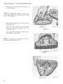
SERVICE MANUAL- 1976 SCORPION RANGE WHIP
;. -
G. Remove spark plugs with spark plug
wrench. (See Fig. 1-21.)
H.
..,-
•
()
Cylinder Heads
Remove cylinder head nuts with a
13 mm socket wrench. Mark cylinder
heads before removal from cylinder.
Re move and discard gaskets. See Fig.
1-22.
I.
Cylinders
FIG. 1-21
Remove the eight (8) cylinder base
nuts using a 13 mm socket wrench and
remove the eight (8) spring washers.
The cylinders may be removed. See
Fig. 1-23.
'
"""""""
1)-;
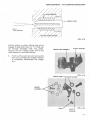
NOTE: IMP 0 R TAN T
If removal of cylinders only is required, care
must be taken that the crankcase seal is not
disturbed . The removal of the PTO cylinder
will allow the placement of two bolts and
nuts with flat washers to apply constant pressure to crankcase assembly. Bolts should be
placed in the center two holes (adjacent to
the fan side cylinder). See Fig. 1-31. The
second cylinder may now be removed.
~'
&,,~
(.)
-
"'\
.
l)
-/
FIG. 1-22
()
F\G. 1-23
1-14
SERVICE MANUAL- 1976 SCORPION RANGE WHIP
J.
l
I
Piston and Wrist Pin
With needle nose pliers, remove
pistons. Heaf the piston with a
propane torch. Heat only to the
piston may still be held in hand.
out.
K.
1
circlips from
heat gun or
point where
Push the pin
To separate the crankcase halves, hold upper
portion of crankcase assembly in one hand,
l ifting slightly and tap the end of the crank case with a soft hammer. The crankcase will
separate and t he crankcase may be
removed. See Fig. 1-24.
FIG. 1-24
c
1- 15
J
SERVICE MANUAL- 1976 SCORPION RANGE WHIP
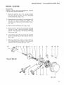
L.
Crankshaft Bearings
To remove crankshaft end bearings, use
bearing puller 444-31 -807-0. See Figs. 1-25,
1-26, 1-27. Slip the puller half shells around
the outer bearing race and around puller
assembly. Slide the retaining ring over the
half shells. Using two (2) 27 mm wrenches,
turn the center bolt clockwise with one
wrench and use the second wrench to hold
the puller body. Before removing the PTO
side crankshaft bearing, insert a 1/2" 20 UNF
bolt, 1 /2" long, to protect the internal thread
of the crankshaft.
FIG. 1-25
_)
FIG. 1-26
)
FIG. 1-'27
1- 16
SERVICE MANUAL· 1976 SCORPION RANGE WHIP
ASSEMBLY
A.
Crankshaft Bearings.
Heat crankshaft bearings in oil (or oven) to
approximately 180 degrees.
Slide bearing on crankshaft.
B.
r
'
Crankcase.
Inspect and clean both halves of crankcase.
The proper sealant material such as Permatex Hy-Tack Spray should be now sprayed
on crankcase sealing surfaces. See Fig. 1-29.
Before installing crankshaft into crankcase
lower half of it will be necessary that all
bearing outer surfaces be wiped clean of
foreign material so that proper sealing will
occur. After installing PTO thrust washer and
oil seal (inside groove of oil seal coated with
light grease) place the crankshaft carefully
into the lower crankcase half and properly
position all components. See Figs. 1-30.
Placement of the upper crankcase half may
now be made. Be certain that the center seal
is lined up with the crankcase split line.
t
BEARING_j
t t
l
FIG. 1-28
L
sEAL
BEARING
Tap upper crankcase half to seat with lower
half.
---
'
'~! '
FIG. 1-29
FIG. 1-30
1-17
SERVICE MANUAL· 1976 SCORPION RANGE WHIP
Install two crankcase holding bolts in the
center holes of the PTO side of crankcase.
(Fig. 1-31) Tighten finger tight.
C.
Piston, Cylinder and Cylinder Heads
FIG. 1-31
The pistons must be clean and free from carbon deposits and the piston rings must fit
freely in their grooves. Rings are marked for
proper side up. The arrow on the crown of
pistons must point toward exhaust side of
engine. Piston pins, needle bearings, check
plates and circlips may now be installed, according to the procedure below. (Always use
new circlips.) See Figs. 1-32, 1-33, 1-34, 1-
35.}
r
.
•
. ,,:
~ ~ ~ ~-
#f:.stl u 1:
)
11
Jj
j
1
FIG. 1-32
/
)
CIRCLIP OPENING HERE----' FIG. 1-33
l-18
SERVICE MANUAL· 1976 SCORPION RANGE WHIP
r
1.
Oil the piston pin end bearings.
2.
In sta ll one circlip in piston.
3.
Heat the piston sufficient ly to allow p i n to
push into piston and install pin.
4.
In stall second circlip. (See Fig.
correct orientation of circlips. )
1-33 for
0
FIG. 1-34
(
~ !\
!!lL--'-iii: it
l\
FIG. 1-35
l -19
SERVICE MANUAL· 1976 SCORPION RANGE WHIP
Install base gaskets on the cylinder studs and
position against the cylinder flanges (see Fig.
1-36). With the use of a ring compressor,
lower cylinders one at a time over the
pistons. Install base washers and nuts finger
tight. See Fig. 1-37, 1-38.
Temporarily install the intake manifold
without gaskets and tighten manifold nuts to
sixteen (16) to eighteen (18) foot pounds.
See Fig . 1-39. Cylinder base nuts may now be
torqued to sixteen (16) to eighteen (18) foot
pounds as outlined on specification page.
The proper piston height can be measured at
the top of the cylinder. The edge of the crown
of the piston must not protrude above the top
of the cylinder with the piston in the top dead
center position. If the piston does protrude
above the cylinder, a thicker base gasket
must be used. See specification page for
dimensions and color coding. It is important
·~- that only one cylinder at a time be adjusted
: or the crankcase will separate and lose it's
sedl-.
FIG. 1-36
'
FIG. 1-37
FIG. 1-38
1-20
)
SERVICE MANUAL- 1976 SCORPION RANGE WHIP
Oil cylinders and pistons before installing
cylinder heads. Install head gaskets with the
wide side of inner metal flange of the
gaskets up toward the cylinder heads.
Torque cylinder head nuts to sixteen (16) to
eighteen ( 18) foot pounds. (See Fig. 1-40).
(
FIG. 1-39
(
FIG. 1-40
1-21
SERVICE MANUAL. 1976 SCORPION RANGE WHIP
D.
Fan Housing and Impeller Bearings
)
Clean fan shaft hub. Install circlips and
spacer. Use grease to hold spacer in place.
Pack bearings in medium grease into
housing with sealed surface outward. See
Figs. 1-18, 1-19. Install fan and shaft.
E.
Fan Housing and Armature Plate.
\
Install new seal in fan housing. Lubricate the 1 l
inner groove of the oil seal with a light '
grease. See Fig. 1-38.
Install new o -ring and apply sealant material
around o -ring surface (see Fig. 1-41 ). Install
the armature plate wires through hole in fan
housing and install armature plate with hold
down screws, washers, and lockwashers. See
Fig. 1-39.
Place fan housing assembly over crankshaft
and position to crankcase assembly. Install
the four Allen head screws and lockwashers
and tighten evenly until fan housing is
against crankcase assembly. See Fig. 1-40.
FIG. 1-38
)
FIG. 1-39
FIG. 1-40
l-22
SERVICE MANUAL· 1976 SCORPION RANGE WHIP
Torque to sixtee n (16) to eighteen (18) foot
pounds. Connect ignition wires to externa l
ignition co il and to connector housing . Check
ground wires for proper position. In stall
ignition cable bracket to fan hou sing.
F.
Intake Manifold
Install spacers, gaskets and intake manifold
(Fig . 1-44). Torque nuts evenly to sixteen
(16) to (18) foot pounds .
G.
Upper Fan Pulley Assembly
In stall the tapered washer. In stall pulley half,
shims, second pulley half, tapered washer,
lock washer and nut. Use 3/16" drill bit or
punch to hold fan assembly and tighten nut.
See Fig. 1-45.
~
oo
·--~
00
FIG. 1-44
H.
Flywheel Assembly
Check advance mechanism for free
operation, lubri cate inside cam surface
(Groov ed area) . Slide assembly over
crankshaft and align key ways.
l -23
SERVICE MANUAL- 1976 SCORPION RANGE WHIP
Install key, lockwasher and nut in that order.
Tighten securely. See Fig. 1-46. Follow
Timing Procedure Section as next step.
I.
Install pulley half, belt, second pulley half,
recoil carrier, lockwashers and bolts evenly
while rotating crankshaft. The proper belt
deflection should be 1/8" on each side.
Proper adjustment can be made by adding or
removing shims between upper pulley
halves. See Fig. 1-47.
J.
FIG. 1-46
Lower Fan Pulley Assembly
~-
({~~
L
Recoil Starter
Install the recoil starter assembly and tighten
securely. See Fig. 1-48.
FIG. 1-47
FIG. 1-48
l -24
SERVICE MANUAL- 1976 SCORPION RANGE WHIP
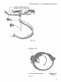
RECOIL STARTER
Disassembly
(See Fig. 1-49 for recoil start breakdown, and Fig .
1-50 for Recoil Starter Assembly.)
1. Remove retaining nut (11), spring washer
( 12) and Thrust washer (8) from threaded
shaft of reel hub. (Fig. 1-51) .
2. Manipulate friction plate (4) on reel hub until
eye end of return spring (9) aligns with
retaining slot. Remove friction plate. (Fig . 152, 1-53).
3. Remove the three pawls (3), (Fig . 1-54) .
4 . Remove return spring (9), spring (6) and cup
washer (7). Fig. 1-53. Note position of plain
end of return spring in the spring retaining
hole in reel hub.
5. Unwind the rope; lift and untie the knotted
end from center hub of reel, remove r ee l (2) .
(Fig. 1-55).
(
6. lift long rolled e nd of main spring (5) from
the fixed spring retaining pin in the ca se and
carefully remove the spring (Fig. 1-56) .
11
12
8 21 4
9
6
7
3
2
10
18
19
20
Recoi I Starter
14
3
14
13
3
5
FIG. 1-49
l -25
SERVICE MANUAL· 1976 SCORPION RANGE WHIP
7. Clean all parts, except rope, using a suitable
cleaning solvent. If rope requires cleaning,
wash it in a solution of soap and water.
Thoroughly dry all parts after cleaning.
8. Inspect all parts for obvious damage and
wear.
FIG. 1-50
)
FIG. 1-51
••
0 .. "Q ' \ ""
FIG. 1-52
~ 'J~':'"
f).
"
FIG. 1-53
1-26
SERVICE MANUAL- 1976 SCORPION RANGE WHIP
~
~-
:.--~·
~~
'I
'\
'
FIG. 1-54
FIG. 1-55
FIG. 1-56
1-27
SERVICE MANUAL- 1976 SCORPION RANGE WHIP
Assembly
1. Replace defective parts.
2. Install main spring as follows:
a.
Secure main spring winding tool, part
number 43-0797-60, or equivalent tool,
circular end up, in a suitable bench vise.
b.
Start with the long rolled end of main
spring (5) and wind spring into circular
end of tool in a clockwise direction. (Fig.
1-57).
c.
Remove tool from vise. Grasp the tool by
its handle and lower the tool, with
spring installed, into case (1) (Fig. 1-58).
d.
Secure the long rolled end of spring over
the fixed spring retaining pin. (Fig. 159). Remove winding tool (Fig. 1-60).
Apply a light film of Lubriplate, or
equivalent, to spring.
FIG. 1-57
3. Secure case, open side up, in bench vise.
4. Tie a knot at one end of !he rope. Secure
knotted end in the center of reel (2). Pull
rope taut and wind entire rope around reel in
an anti-clockwise direction until the free end
protrudes through the notched section of the
reel.
5. Apply a light film of Lubriplate, or
equivalent, to center hub of case and install
the reel. Push down and rotate reel in an
anti-clockwise direction until the hook engages with the free end of main spring. Ten sion will be felt when reel and spring are properly engaged. (Fig. 1-61, 1-62).
FIG. 1-58
6. Rotate reel a maximum of three complete
turns in an anti-clockwise direction. Do not
exceed three turns; hold reel in this position
and feed free end of rope through case at the
rope guide hole. Install rope guide. Loosely
knot the rope to prevent recoil.
7. Apply a light film of Lubriplate or equivalent
to pawls (6) and install them on the reel in
the pawl retainers. (Fig. 1-63). (See Fig. 1-49
for part identification numbers.)
8. Install cup washer (7) flat side down, spring
(6) and return spring. Ensure that plain end
of return spring is properly engaged in the
retaining hole in reel hub.
1-28
r
FIG. 1-59
SERVICE MANUAL- 1976 SCORPION RANGE WHIP
9. Install friction plate (5) over reel hub.
Manipulate plate until eye end of return
spring engages and locks crosswise in
retaining slot.
10. Rotate friction plate until the three notches
are aligned with pawls when pawls are at
the recoil position.
11. Install flatwasher (8), lockwasher (12) and
nut (11 ). Tighten nut securely.
12. Untie the temporary knot in free end of rope
and inst.all the rope handle. Tie a permanent
knot and fit handle securely.
FIG. 1-60
13. Check starter for proper operation. When
handle is pulled outward, pawls should move
outward.
(
NOTE:
If main spring is to be installed without the
use of a spring winding tool, wind main
spring into case in an anti -clockwise direction. Clockwise installation on the winding
tool is necessary to ensure correct anticlockwise installation of the spring when tool
is placed upside down in the case.
FIG. 1-61
FIG. 1-62
(
FIG. 1-63
1-29
SERVICE MANUAL- 1976 SCORPION RANGE WHIP
TIMING PROCEDURE
NOTE: Recoil starter, carrier, lower pulley assembly and spark plugs should be removed before
beginning timing procedure.
A.
Install the dial indicator assembly into spark
plug hole of No. 1 cylinder (P.T.O. side). See
Fig. 1-64.
B.
Attach negative lead of ohmmeter to engine
ground. Attach posit ive lead of ohmmeter to
No. 1 cylinder terminal in connector housing.
See Fig. 1-65.
C.
FIG. 1-64
Rotate flywheel
counterclockwise
until
points are on the high side of cam on No. 1
cylinder. Points are at maximum open position observed through opening in flywheel.
Check gap with wire gauge and adjust to
.015 if necessary. See Fig. 1-66.
)
FIG. 1-65
FIG. 1-66
1-30
SERVICE MANUAL· 1976 SCORPION RANGE WHIP
D.
Rotate flywheel
dead center and
selector knob on
meter needle will
See Fig. 1-67.
counterclockwise to top
adjust dial to zero. Place
ohmmeter to R x 1. Ohmindicate a closed circuit.
FIG. 1-67
Move the centrifugal weights in flywheel to
the full advanced position. See Fig. 1-68.
FIG. 1-68
Rotate flywheel counterclockwi se one com plete revolution to between . 102 and . 112.
See Fig. 1-69.
FIG. 1-69
1-31
SERVICE MANUAL· 1976 SCORPION RANGE WHIP
At this point the breaker points for No. 1
cylinder should open. (Break contact) This
will show on the ohmmeter. Needle will
move to the left. If this does not occur, the armature plate needs adjusting. This is accomplished by loosening the hold-down
screws and turning plate either left or right
while observing needle action. With proper
positioning, needle should move to left with
slight movement of armature plate and
flicker back with opposite plate movement.
Tighten hold-down screws securely. Re-check
procedure. See Fig. 1-70.
NOTE:
In Fig. 1-70 flywheel has been removed for
clarity of illustration.
()
FIG. 1-70
l
E.
Remove dial indicator assembly and install in
No.2 cylinder (fan side). See Fig. 1-71.
Attach positive lead of ohmmeter to No. 2
cylinder terminal in connector housing.
Rotate flywheel counterclockwise to top
dead center. Set dial indicator to zero. Again
move centrifugal weights in flywheel to full
advanced position. Rotate flywheel coun.terclockwise while watching dial indicator.
The needle must make one full revolution
and stop at between .1 02 and .112. At this
point, needle should move to left indicating
point contact open. If this does not occur,
points need slight adjustment. Re-check
procedure.
FIG. 1-71
( )
1-32
SERVICE MANUAL- 1976 SCORPION RANGE WHIP
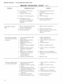
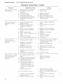
TROUBLE SHOOTING CHART
TROUBLE
Manual starter rope
comes out but pawls
don't engage.
REMEDY
PROBABLE CAUSE
1. lack of friction plate
2.
return spring action .
Defective pawls.
1. Check friction plate return spring. Replace as required.
2. Check for broken or bent
pawls. Replace pawls as requi red.
Manual starter rope
doesn't return.
1. Recoil spring broken or
bent.
2. Pulley hou sing warped or
bent.
3. Starting pull e y worn .
1. Replace spring.
2. Replace housing.
3 . Replace pulley.
(
Hard to start or
won't start.
1. Inoperative diaphragm or
2.
inlet check valve.
Fuel enrichening valve not
not pulled up to start.
1. Refer to Carburetor
Section.
2. Ensure enrichening valve is
pulled up.
3. Spark plug s improperly
3.
gappe d, dirty or broken.
4 . Magneto breaker points
4.
improperly gapped or dirty.
5. Head gasket blown or leaking. 5.
6 . Empty gas tank or improper
6.
fuel mixture.
7. Water in fu e l system.
7.
8. Weak coil or condenser.
9. Obstructed fuel system .
(
Remove plugs. Clean, adjust or
install new plugs.
Clean, adjust or replace
points.
Replace gasket.
Refill tank with specified
fu e l/oil mixture.
Drain fuel from carburetor.
Add carburetor de-icer as requi red to fuel.
8 . Replace faulty coil or
condenser.
9. Disconnect fuel lines .- Clear
obstruction. Flush system . Connect fuel lines.
1-33
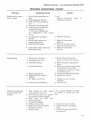
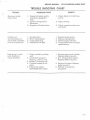
SERVICE MANUAL - 1976 SCORPION RANGE WHIP
TROUBLE SHOOTING CHART
TROUBLE
12. Engin e not timed properly.
13. Secondary wire not
connected or spark plug
protector not in stalled
pro pe rly.
Imposs ible to a dju st
idl e.
Mi ss ing at low spee d
o r w o n't idle smoothly
or slowly.
l. Spark retardin g mechanism
not working properly.
2. Pistons or rings worn.
3. Faulty carburetor.
l. Incorrect carbure tor idle
2.
3.
4.
5.
6.
7.
8.
Missing at hig h speed
or intermittent spark.
1-34
REMEDY
PROBABLE CAUSE
10. Air leak in crankcase or
inle t sy st e m.
11. Primary wire broken.
adjustment.
Spark plug s imprope rly
gapped o r dirty.
He ad ga sk e t blown or
leaking.
Loose or broken magneto
wire s.
Magneto breaker points
imprope rly gapped or
di r ty.
Weak coil or cond e n ser.
Improper fuel mixture.
(1) Too much oil
(2) Too little oil
Leaking crankshaft seal.
l. Spark plugs improperly
gapped or dirty.
2. Loose or broken magneto
wire s.
3. Magneto breaker points
improperly gapped or dirty.
4. Weak coil or condenser.
5 . Heat range of spark plug
incorrect.
6. Leaking h ead gasket.
7 . Engin e improperly timed.
(CONT.)
10. Check crankcase pressure
(3-6 PSIG)
11. Repair or replace primary
wire.
12. Re-time engine.
13. Secure secondary wire or
spark plug protector.
l. Re pair retard mechanism.
2. Replace as necessary.
3. Check carburetor, check valve.
Refer to Carburetor
Section.
l. Adjust idle-Refer to
Carburetor Section.
2. Clean , adjust or install new
plugs.
3. Replace gasket.
)
4. Repair or replace wires.
5. Adjust , clean or inst all new
points.
6. Replace coil or condenser.
7. Refuel , usi ng specified fuel / oil
mixture.
8. Replace seal.
l. Clean, adjust o r install new
plugs.
2. Repair or replace w i res.
3. Clean, adjust or install new
points.
4. Replace coil or condenser.
5. Inst all specified spark plugs.
6. Replace head gaske t .
7. Re-time engine.
)
SERVICE MANUAL· 1976 SCORPION RANGE WHIP
TROUBLE SHOOTING CHART
TROUBLE
Coughs, spits, slows
down, surges
l . Idle or high speed jets too
lean.
2. Leaking gasket flange.
3 . Inlet control level set too
low.
4. Pulsation line obstructed.
5. Fuel pump not supplying
enough fuel due to:
(l) Punctured diaphragm.
(2) Inoperative inlet check
valve.
6. Crankcase not properly
sealed.
7. Idle or main carburetor
nozzle obstructed.
8. Fuel line obstructed.
9. Carburetor inlet needle and
seat obstructed.
Overheating
REMEDY
PROBABLE CAUSE
l. Carburetor too lean.
2. Carburetor too rich.
3. Incorrect timing.
4. Too much carbon.
5. Spark plug too hot.
6. Engine fan belt loose or
l. to 5.
Adjust carburetor.
Carburetor Section.
Refer
to
6. Reseal crankcase.
7. Refer to Carburetor
Section.
8. Remove fuel line. Clear
obstruction. Replace line.
9. Refer to Carburetor
Section.
1. and 2. Adjust carburetor.
Refer to Carburetor Section.
3. Retime eng ine to Specifications.
4. Remove cylinder heads. Clean
top of pistons and inside
compression chamber. Clean
out exhaust port.
5. Install specified spark plugs.
6. Replace or adjust.
broken .
7. Air leak in manifold.
7. Tighten nuts or change
8. Crankcase seal leaking.
8. Fit new seal.
gasket s.
Vibrates excessively
or runs rough and
smokes.
needle or high speed
carburetor jet too rich.
Enrichening valve not operating properly (bent linkage) .
Float lever too high. (carburetor floods).
Air bleed plugged.
Muffler obstructed.
Engine not secured tightly
to engine support.
Water in gas.
1. Idle
2.
3.
4.
5.
6.
7.
l to 4 . Adjust needle or change
jet. Refer to Carburetor Section.
5. Check and dear muffler.
6. Tighten engine mounting
bolts .
7. Add carburetor de-ice fluid
as required.
1-35
SERVICE MANUAL- 1976 SCORPION RANGE WHIP
TROUBLE SHOOTING CHART
TROUBLE
Won't start, kicks back
and backfires.
1.
2.
3.
4.
5.
6.
No acceleration, low
top R.P .M., hard to
start.
1. Spark plugs improperly
2.
3.
4.
5.
6.
7.
8.
Good spark but
engine runs on one
cylinder.
PROBABLE CAUSE
Spark plug wires reversed.
Flywheel key missing or
sheared .
Faulty condenser.
Improper timing.
Faulty breaker points.
Unhooked spark retarding
mechanism- or spring
broken.
gapped or dirty.
Magneto breaker points
improperly gapped or
dirty.
Faulty coil or condenser.
Loose or broken magneto
wires.
Blown head gasket.
Float lever adjustment too
high.
Crankcase leaking.
Main (high speed) jet t0o rich.
1 . Leaking cylinder head.
REMEDY
Install
wire
correctly.
1.
2. Replace key.
3.
4.
5.
6.
(
Replace condenser.
Re -time engine.
Adjust or replace points.
Reconnect mechanism or
replace spring.
1. Clean, adjust or install new
plugs.
2. Clean, adjust or install new
points.
3. Replace coil or condenser.
4. Repair or replace magneto
wires.
5. Replace head gasket.
6. Refer to
Carburetor Section.
7. Install new seal.
8. Change jet.
1. Check head for warps, cracks.
Install new gasket and
cylinder head.
2. Repair or replace wires.
2. Magneto wires broken
inside (coil ground
broken).
3. Cracked cylinder wall.
4. Defective spark plug.
3. Replace faulty cylinder.
4. Clean, adju3t or install new
5. Breaker points improperly
5. Re-adjust points.
l )
plug.
gapped.
No acceleration. Idles
well but dies down
when put to full
throttle.
6. Crankcase seal leaking.
6. Install new seal.
1. Low speed needle set too
1. to 6.
2.
3.
4.
5.
6.
7.
lean.
Dirt behind needle and seat.
High speed jet obstructed.
Float lever set too low.
Silencer obstructed.
Fuel pump not supplying
enough fuel due to:
( 1) Punctured diaphragm
(2) Non-functioning check
valves.
Fuel line obstructed.
Adjust carburetor.
Refer to Carburetor
Section.
7. Remove fuel line. Clear
obstruction. Replace line.
8. Not enough oil in gas.
8. Refuel, using specified fuel/oil
9. Breaker points improperly
9. Adjust, clean or install new
mixture.
gapped or dirty.
10. Engine improperly timed.
1-36
points.
10. Re-time engine to specifications.
()
SERVICE MANUAL· 1976 SCORPION RANGE WHIP
TROUBLE SHOOTING CHART
r
TROUBLE
No power under
heavy load.
REMEDY
PROBABLE CAUSE
l. Magneto breaker points
improperly gapped or
dirty.
2. Ignition timing too far
advanced.
3. Magneto coil plate loose.
l. Clean, adjust or install new
points.
2. Adjust timing.
3. Check magneto and secure
coil plate.
(
Cranks over
extremely easy on
one or both cylinders.
Loss of compression.
l.
2.
3.
4.
Engine won't crank
over. Unable to
rotate flywheel.
l. Piston rusted to cylinder
wall.
2. Crankshaft seized to
bearing. (main or rod)
3. Broken connecting rod.
4. Flywheel seized to coi l
plate.
5. Engine improperly
ass e mbled after repair.
Scored piston.
Blown head gasket.
Loose spark plug.
Head bolts not tight.
l.
2.
3.
4.
Replace faulty piston.
Replace head gasket.
Check plug for security.
Torque head bolts to proper
specifications.
l. Remove piston and cylinder.
Replace defective parts.
2. &3. Disassemble engine.
Replace defective parts.
4. Remove flywheel. Replace
defective parts.
5. Recheck re-assembly
procedure.
(_
1-37
0
()
()
r
...
1976
Scorpion
Range Whip
(
'
Service Manual
Carburetor
Section
2- 1
SERVICE MANUAL- 1976 SCORPION RANGE WHIP
Functional Description:
(
• General:
The purposes of the carburetor are (1) to provide the amount of fuel that the engine needs in
operation and (2) to properly mix the fuel with air so that it w i ll vaporize.
Pulsations, from the engine crankcase through the impulse line, actuate the carburetor
fuel pump to move the fuel from the fuel tank into the carburetor. The fuel level in the car buretor fuel reservoir is maintained by a float-controlled needle valve that opens as the
level drops and closes as the fuel rises to a specific level. The engine fuel demand determines the· air flow through the carburetor throttle bore. The air flow rate varies the
pressure differential on the fuel in the reservoir. This pressure differential forces fuel into
the thrott le bore through one or more openings depending upon the operational phase of
the engine.
( )
(
'2 -2
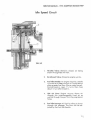
SERVICE MANUAL- 1976 SCORPION RANGE WHIP
The function of each element of the carburetor is described below. (See Fig . 2-1 ) .
(
1. Engine Impulse: Actuates fuel pump diaphragm with alternating pressurevacuum pulses from engine revolutions.
2. Fuel Pump Diaphragm: Fluctuates in response to engine impulse. Draws
fuel into surge chamber with upward, vacuum stroke, of engine piston.
Pushes fuel with pressure downward stroke of engine piston, through
outlet check valve.
3. Fuel Inlet Fitting: Fuel drawn through line from tank.
4. Fuel Channel: Fuel is routed into surge chamber.
5. Surge Chamber: Fuel accumulates waiting for inlet check valve to open for
passage at engine piston down stroke.
6. Surge Diaphragm: Reciprocates with pump diaphragm balancing to atmospheric pressure, cushions pulsations.
7. Leaf Spring: Assists pump diaphragm when engine impulses are weak at
starting and idle circuits.
8. Inlet Check Valve: When opened by engine vacuum, allows fuel passage
from surge chamber into pump chamber, feeding to outlet check valve.
9. Outlet Check Valve: Opened by engine pressure pulse forcing fuel down
through inlet valve needle passage.
10. Fuel Channel: Routes fuel to inlet needle valve.
11. Filter Screen: Fue l is filtered before fed into inlet needle valve. Cleanse
screen when servic ing by flushing or air stream.
12. Inlet Valve Seat: Hole through which fuel feeds when needle valve drops
slightly away.
13. Inlet Needle Valve: As float rises it pushes valve into seat closing off fuel
passage. When float drops, needle opens hole in seat allowing fuel to flow
into bowl reservoir.
14. Lever: Raises and lowers with float to activate inlet needle valve.
15. Float: Raises and lowers to maintain fuel level as fuel is used.
16. Fuel Bowl Reservoir: Constant level of fuel stored and maintained by float
action on lever to open and close inlet needle valve.
2 -3
SERVICE MANUAL· 1976 SCORPION RANGE WHIP
The four operationa l phases of the Walbro Float Carburetor used on the 1976 Range Whip
are:
( 1) Start ing oper a t ion
(2) Idle operation
(3) Part-throttle operation
( 4) Fu 11-throttle operation
)
Detai led performance of the carburetor in each of the four phases is described below.
Figures 2-1 through 2-4 are schematic diagrams and as such are accurate, functional
representations of the carburetor, but in some features deviate from actual physical appearance.
Starting Circuit
FIG. 2-1
COLOR
2 -4
CODE
A.
Enrichment Valve: : In operation when
control lever, is up (vertical). elimates
choke. Like opening a faucet an extra
column of fuel is introduced through
the valve into carburetor bore as
engine is cranked; offering easier,
quicker starts. This valve may be left
open until engine is warm .
B.
Throttle Valve: Must be at idle position
freeing both hands for starting. Required
air is drawn in th r ough the air bleed
ports mixing with the fuel.
C.
Start & Idle Fuel Feed Tube: Fuel is
drawn by engine vacuum up tube,
through part throttle passage into
Enrichment Valve and idle circuit.
D.
Enrichener & Idle Feed Ports: Tube picks
up at these two pockets for starting full
volume.
E.
Air Bleeds: Vacuum draws in air at these
four points to mix with fuel in metered
ratio.
F.
Enrichener Port: Fuel and air mixture
flows into throttle bore when enrichener
valve is open.
G.
Idle Needle: Fuel is also drawn through
the idle needle circuit which is pre-set
for the idle position .
H.
Idle Feed Hole: Additional fuel is
discharged from this port into throttle
bore for sta r ting.
Crankcase
Impulse Air
J
SERVICE MANUAL- 1976 SCORPION RANGE WHIP
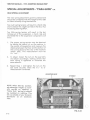
Idle Speed Circuit
FIG. 2-2
(
1.
Throttle Valve: Remains closed, air being
drawn through Idle Air Vent.
2.
Enrichment Valve: Closed as engine warms.
3.
Fuel Idle Needle: As engine requires, needle
is turned in to lean mixture or turned out to
allow greater fuel flow (I ike a water faucet).
During break-in, open 1 1/2 turns then close
about 1/ 2 turn after break-in.
4.
Idle Air Vent: Engine vacuum draws air
through this interchangeable fixed jet as
well as through the part throttle progression
holes.
5.
Fuel Idle Passage: All fuel for idling is drawn
through this passage . The flow can be aajusted by the Fuel Idle Needle.
2-5
SERVICE MANUAL- 1976 SCORPION RANGE WHIP
Part Throttle Circuit
1.
Throttle Valve: Fuel is being fed through
idle circuit. As the Throttle Valve is
opened a series of three holes is exposed progressively offering smooth acceleration as they increase fuel flow.
2.
Part Throttle Holes: Three holes are
skillfully located and carefully sized to
feed measured fuel drawn by vacuum as
each hole is allowe d to flow with
opening of the Throttle Valve.
3.
Venturi: This acts as a restriction to the
air rushing through the carburetor bore
into the engine to fill the vacuum left by
the piston movement. As the air velocity
incre ases at the venturi the pressure is
dropped according to the degree Throttle Valve is opened. As the Part Throttle
holes are exposed to the drop in
pressure, fuel rushes in to help bring the
air pressure up. The Idle Feed hole con tinues to flow for the same reason.
4.
Air is also fed
FIG. 2-3
)
by the Idle Air Vent Jet,
affecting the vacuum which lifts fuel up
the feed tube. A smaller jet delivers less
air, and therefore a richer mixture,
especially at "early" part throttle.
2-6
)
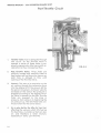
SERVICE MANUAL· 1976 SCORPION RANGE WHIP
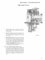
High Speed Circuit
r
(
l.
Throttle Valve: Valve is wide open to a llow
full air and fu e l flow, metered to control top
engine speed.
2.
Main Fuel Nozzle: As the throttle opens , air
velocity increases through the venturi and
the resu ltant vacuum draws fuel from the
main nozzle.
3.
(
FIG. 2-4
High Speed Fixed Jet: Fuel is fed to the fixed
jet hole from the bowl reservoir. The hole
may be varied in size by exchanging the jet
on which sizes are stamped . Larger engines
require larger jet holes for greater fuel consumption . Too large creates a rich mixture,
too small a dangerous lean mixture.
Note: High altitudes require a sma ll er jet
to compensate for the thinner air.
Note: Air Intake Silencer: Regulations require the noise created by air rushing into
the carburetor be reduced to a minimum. All
WF models are finely calibrated in tune with
original equipment Silencers, both Intake
and Exhaust. Anytime the characteristics of
either are changed or removed a risk of
burning out an engine exists and Warranty is
void.
2-7
SERVICE MANUAL- 1976 SCORPION RANGE WHIP
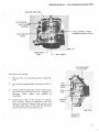
Carburetor Disassembly
Fuel Pump and Gaskets
1.
Remove four (4) mounting screws. (See
FIG. 2-5).
2.
rrUNTING SCREWS (4)
Lay out parts in sequence shown in FIG.
2-6. Do not remove rubber fuel pump
valves
unless
repla cements
are
available.
WF-17
3.
Inspect all parts, openings, needles,
valves, valve seats and any other functioning part for clogging or damage.
(See Fig. 2-7).
4.
Clean parts with a mild solvent or
regular fuel mixture. Repair or replace
parts as necessary.
FIG. 2-5
FUEL
INLET
)
't' w
p
til
J
·G
D
FIG. 2-6
2-8
D
c
. • :.
~
!'
"'
...,;;
*~7H
E
F
B
A
A.
Fuel pump cover assembly
B.
Fuel pump leaf spring
c.
Pump gasket
D.
Pump diaphragm
E.
Fuel pump body assembly
F.
Surge chamber diaphragm
G.
Surge chamber gasket
H.
Throttle bracket plate
I.
Fuel pump to body gasket
J.
Idle Fuel feed tube
(Also see FIG. 2-13)
Carbu retor body assembly
with float bowl assembly
K.
)
SERVICE MANUAL- 1976 SCORPION RANGE WHIP
FUEL CH ANNEL
----;;-------i;o· :
INLET TO SUR
CHAMBER
-~--FUEL
CHANNEL-SURGE
CHAMBER TO NEEDLE VALVE
PARTTHROTTLE-:----:HOLES
FIG. 2-7
ENRICHENER
PORT
(
FUEL ENRICHENER
VALVE LEVER
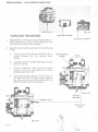
Fuel Bowl and Gasket
1.
Remove four (4) mounting screw s. (See FIG.
2-8)
2.
Lay out parts sequentially as shown in FIG. 2-
9.
3.
Check all parts openings , valv es, valve seats
and o th e r functioning parts f o r clogging o r
damage. Clean, repair and replace as
necessary.
4.
Clea n parts with a mild so lven t or regular
fuel mixture. Clean all sedim e nt from the
bottom of the bowl. Remove th e main jet and
idle feed tube. Blow air through th e idle f eed
circuitry and main air bleed circuit.
IDLE
SPEED ---11-'11~
SCREW
LEVER
FIG. 2-8
MOUNTING
SCREWS (4)
2-9
SERVICE MANUAL. 1976 SCORPION RANGE WHIP
MAIN AIR JET
Carburetor Reassembly
1.
Reassemble in reverse process of disassembly. Install components on top of the carburetor first
followed by the float bowl assembly.
2.
Specific care should be exercised in the following
areas:
a.
b.
The fuel pump leaf spring should be flat to
center between the two castings when
seated.
FIG. 2-9
FUEL BOWL GASKET
FUEL BOWL ASSEMBLY
FLOAT SUPPORT
SPRING
FLOATS
I
Carefully position the idle feed tube and tube
pressure spring.
..
.
c.
During installation, wind the float support
spring 1/2 turn from rest position for correct
loading. (See FIG. 2-1 0)
d.
Slide the fuel bowl gently over the point of
the idle feed tube. A slight tension against
the tube pressure spring should be felt just
before the bowl seats on its gasket.
~
FIG. 2-10
FLOAT VALVE
LEVER
FIG. 2-11
2-10
')
SERVICE MANUAL- 1976 SCORPION RANGE WHIP
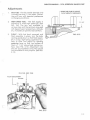
Adiustments
1.
IDLE FUEL- The idle needle (See FIG. 2-8)
is usually set one ( 1) turn open. The setting will vary with operator prefere nce
or changing conditions.
2.
HIGH SPEED FUEL - The fuel supply is
limited by a fixed high speed jet. (See
FIG. 2-6) The jets are available in
various sizes and the optimum size u sed
will depend upon temperature, altitude,
etc. A smaller jet permits less fuel flow.
3.
FLOAT - With fuel bowl removed, and
float assembly in place, turn the body
casting upside-down so that float assem bly is at top. Sight along uppermost surface of float and adjust by bending
metering lever so that top surface of
float is 1 1 /16" above body casting surface. (See FIG. 2-12) Adjustment may
also be accomplished using the special
tool available for this purpose. (See FIG.
BEND THIS LEVER TO ADJUST
FLOAT HEIGHT IF NECESSARY.
t
1 1I 16"
FIG. 2-12
2-13)
(
IDLE FUEL FEED TUBE
FLOAT ADJUSTMENT
I
GAUGE
L,.
.
f;'""'
\f
~
(
FIG. 2-13
2-ll
l)
1976
Scorpion
Range Whip
Service Manual
Electrical
Section
r
.,)
3-1
SERVICE MANUAL- 1976 SCORPION RANGE WHIP
ELECTRICAL SYSTEM
The Scorpion Range Whip Electrical System is divided
into four ( 4) subdivisions:
LIGHTING COILS
A. Power Generation
B.. lgn it ion
C. Voltage Regulation
D. Electrical Control and
Distribution
POWER GENERATION
Functional Description :
Electrical AC power, used for lighting and tachometer operation is generated by rotating a permanently magnetized flywheel around two stationary coi Is ( 1-120 watt and 1-23 watt). The noload voltage increases with engine RPM and could
reach 32 volts RMS. To maintain the voltage at the
required system level {13-14 volts). an external
voltage regulator is utilized. (See VOLTAGE
REGULATION)
FIG. 3-2
MAIN ELEMENTS:
1.
2.
3.
Magnetic Flywheel
120 watt coil (mounted on stator plate)
23 watt coil (mounted on stator plate)
FIG. 3-1 POWER GENERATION SCHEMATIC
3-2
ENGINE
CONNECTOR
FIG. 3-3
u
SERVICE MANUAL- 1976 SCORPION RANGE WHIP
IGNITION
f
Functional Description:
(See SCHEMATIC FIG. 3-7).
magneto type ignition. An electrical current is
generated by rotating a permanently magnetized
flywheel about the ignition coil. The current
initiated in this coil in turn energizes the primary
coils of the external ignition coils. The secondary
coils of the external ignition coils are situated in
the force field generated by the primary coils.
When the points close, causing an interruption of
the current flow through the primary winding, its
force field immediately collapses and generates a
very high voltage in the second coil. This voltage in the
region of several thousand volts will jump the spark
plug gap causing ignition to begin.
The collapsing lines of force cut through the primary
windings, raising the voltage in that circuit also.
As this occurs, the condenser absorbs the generated current to reduce the tendency to overload
the points. As soon as the voltage level in the
primary winding drops below that of the condenser,
current again flows in the original direction,
energizing the system. This occurrence and the reversal happens several times each cycle creating a
powerful, long duration spark for more reliable
ignition.
FIG. 3-4
MAIN ELEMENTS:
1.
2.
3.
4.
5.
Ignition Coil (Stator)
Condensers (2)
Breaker Points (2)
Ignition Coils (External) (2)
Spark Plugs (2)
FIG. 3-5
3 -3
SERVICE MANUAL· 1976 SCORPION RANGE WHIP
(STATOR)
SEE ENGINE DISASSEMBLY
~
(SECTION 1) FOR FLYWHEEL
AND STATOR REMOVAL
FIG. 3-6
IGNITION COIL (STATOR)
CONDENSER
HI·
~SPARK
PLUG
15
EXTERNAL IGNITION COILS
15
~SPARK PLUG
-.J
ENGINE CONNECTOR
3-4
FIG. 3-7 IGNITION SCHEMA TIC
SERVICE MANUAL - 1976 SCORPION RANGE WHIP
t----
STATOR IGNITION COIL TO
EXTERNAL COIL CONNECTORS
FIG. 3-8
EXTERNAL COIL
FIG. 3-9
3-5
SERVICE MANUAL· 1976 SCORPION RANGE WHIP
VOLTAGE REGULATION
Functional Description:
The voltage regulator is connected across the
lighting coils in parallel with the electrical load
!\",·.·
of the sled . Under operating conditions, the
voltage drop across the regulator is such that
13.8 volts RMS is . supplied to the snowmobile
lighting circuit.
FIG. 3-11
\
YELLOW
REGULATOR
CONNECTOR
TRANSISTOR
SCR
MOUNTING
VOLT AGE REGULATOR SCHEMATIC
BRACKET
FIG. 3-12
3-6
SENSING
ELEMENT
SERVICE MANUAL· 1976 SCORPION RANGE WHIP
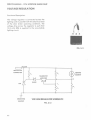
VOLTAGE REGULATOR CHECKS
(
1. Resistance across regulator
Two most common catastrophic failure modes of the regulator may be identified by simply
checking the resistance of the regulator.
a. Burned out sensing element.
Normal resistance across the regulator is approximately 155 - 160 . The symptom of a
burned out sensing element is a significantly increased resistance reading.
b. Shorted SCR.
Shorted SCR is characterized by a sign ificantly reduced resistance reading .
2. Set point check
Use test circuit as shown below. Read voltage across regulator. Value should be 13.8
±
.5V.
lOOW
s...n.
OPEN
• TEST
120V
REGULATOR SET POINT TEST CIRCUIT
FIG. 3·12
3-7
SERVICE MANUAL- 1976 SCORPION RANGE WHIP
ELECTRICAL CONTROL
AND DISTRIBUTION
Functional Description
Power is supplied continuously to the broke
light switch, so that any time power is being
generated, the brake light will go on if the brake
is applied.
Power to all the other items is supplied through the
ignition switch in the "LIGHTS" mode.
HEADLIGHT HARNESS CONNECTOR
IGNITION SWITCH
CON
Grounding of the System is accomplished at three
locations:
1.
2.
3.
VOLTAGE REGULATOR
CONN
To the chassis at the rear end
To the chassis from wire harness
at eng. connector.
To the stator plate on the engine
MAIN ELEMENTS:
1.
2.
3.
4.
"
7.
8.
Main Wiring Harness
Seat Wiring Harness
Taillight Wiring
Harness
Safety Stop Switch
Break light Switch
Hi-Lo Beam Switch
Ignition Switch
Headlight Harness
HI-LO
BEAM SWITCH
CONNECTOR
)
----~1
BRAKE LIGHT
SWITCH
CONNECTOR
,
SPEEDOMETER/TACHOMETER CONN. -~...
SEAT HARNESS
CONNECTOR
t
ENGINE CONNECTOR
SAFETY STOP ,SWITCH
FIG. 3-14
SAFETY STOP
SWITCH/HARNESS
~-------HI-LO
SWITCH/ HARNESS
-----,.,..~
HEADLIGHT HARNESS,~
BRAKE LIGHT
SWITCH/HARNESS
.J
FIG. 3-15
3-8
'
'
I
r
SAFETY
STOP
I SWITCH
////////
/
/
~
/
I
LLIGHTING
COILS
IGNITION
COIL
~
/
/
/
/
E
LIGHT
SWITCH
I
/
/
IGNITION
----~~...._SWITCH
•
:I:
m
I
)>
c
~
C)
:I:
....
"'m
::111:1
~
n
m
3:
)>
z
c:
)>
.
~
TAILLIGHTS
BRAKE LIGHT
I
HI-LO
SWITCH
-.....
-a
o-
"'n0
.,
::111:1
0
z
VOLTAGE
REGULATOR
"'
.0
::111:1
c::J
WIRING SCHEMATIC (COLOR CODED)
ELECTRICAL DISTRIBUTION & CONTROL
1976 RANGE WHIP
FIG. 3-15
)>
zC)
m
:e:I:
.,
SERVICE MANUAL· 1976 SCORPION RANGE WHIP
•
WIRING CODE (ELECTRICAL DISTRIBUTION & CONTROL)
COLOR
Black
FUNCTION
Hot
Hot
Hot
Eng. Connector
(Engine Ignition Coi l)
Safety Sw itch Connector
Brake Swi t ch
TO
Safe ~y Sw itch Connector
Ignition Sw itch
Brake Switch Connector
Safety Switch Connector
Hot
Hot
Engine Connector (Engine
Ignition Coi l
Safety Switch Connector
Brake Swi t ch Connector
Blue
Hot (Hi)
Hi -Lo Beam Switch (Hi)
Headlight Connect or (Hi)
Brown
Ground
Ground
Ground
Ground
Engine Connector
Engine Connector
In strum en t Connector
Ta illi ght
Chassis (Rqll Bar Bracket)
In strument Connector
Headlight Connector
Chassis (Tunn e l)
Green
Hot
Ignition Switch Connector
Electric Start (R egu lato r
Connector)
Orange
Hot
Engine Connector
In strument Connector
Orange/Black
Ground
Engine Connector
Instrument Connecto r
Red
Hot
Brake Switc h Connec t o r
Hot
Voltage Regulator
Connector
Brake Switch Connector
Igniti on Swit ch Connec tor
Tan
Hot
Brake Switch Connector
Brake Lig hts
Wh ite
Hot (LO)
Hi-Lo Beam Switch
Connector (Lo)
Head light Connec t o r (Lo)
Yellow
Hot
Hot
Hot
Ignition Swi t ch Connector
Ignition Switch Connect or
Hi -Lo Beam Switch
Connector
Taillights
Hi -Lo Beam Switch
Connector
In strum e nt Connector
Yellow/Black
Ground
Eng in e Connector
Volta ge Regulator
Connector
Yellow/R ed
Hot
Engine Connector
V ol tag e Regulator
Connector
Black/White
3-10
Hot
FROM
(
Ignition Switch Connector
Brake Switch
i
SERVICE MANUAL· 1976 SCORPION RANGE WHIP
TROUBLE SHOOTING (ELECTRICAL)
TROUBLE
No lights
REMEDY
Open Circuit:
Faulty Switch(s)
Separated Connector(s)
Cut Wiring
Repair or replace faulty
or damaged element.
Wiring shorted to ground:
Damaged Insulation
Repair or replace damaged
or faulty element.
Faulty Regulator (Shorted SCR)
Replace regulator.
Shorted or open lighting coil.
Replace armature plate.
Faulty regulator- Incorrect
regulator set point (too low).
Replace regulator.
Faulty regulator -Incorrect Set
Point (too high).
Replace regulator and failed
bulbs.
Burned out
lights (individual)
Failed bulb.
Replace bulb.
Burned out lights
Intermittent short in wire harness.
Repair or replace wire harness.
Engine won't run
l. Open or shorted windings in
ignition coils (stator).
2. Open or shorted windings.
in external ignition coil.
3. Shorted condenser- dirty or
worn.
4. Damaged (burned) points.
l. Replace armature plate.
Dim lights
Burned out
lights (all)
(
PROBABLE CAUSE
Weak or no
spark
Engine won't runAdequate spark.
l. Burned or fouled plugs.
2. Replace external coil.
3. Replace condenser.
4. Replace points.
.1. Replace plugs. Determine that
correct plugs are being used.
CHECK ENGINE TROUBLE
SHOOTING.
2. See Engine Trouble Shooting
Section
Unacceptable
Engine Performance
See Engine Trouble Shooting
Section
3 - ll
r)
(__)
r·
1976
Scorpion
Range Whip
-Service Manual
)
Clutch/Drive
Section
,
.
4-J
SERVICE MANUAL· 1976 SCORPION RANGE WHIP
DRIVE SYSTEM
Functional Description:
(
)
The main elements included in this system are:
1. Drive Clutch
2. Drive Belt
3. Driven Clutch
4. Chain Case with sprockets, chain and chain tensioners.
5. Drive shaft with track drive sprockets.
The power from the engine is transmitted through this system to the track in
sequence of elements listed above to propel the machine.
The drive clutch, belt and driven clutch serve as a torque converter. The torque
converter on the snowmobile "down shifts" to a lower ratio as the track load increases as readily as it "up shifts" when the track load decreases.
To accomplish the automatic shifting, the movable sheave of the driven clutch
is fitted with a helical ramp which is guided. This sheave is controlled by a
spring pre-stressed in torsion and compression to hold the sheaves together at
the maximum pitch diameter. The drive clutch cover has a set of centrifugal
weights and helical guides. The drive movable contains a mating set of ramps.
A spring automatically positions the movable drive clutch at the minimum
pitch under zero and idle speed conditions.
Under acceleration, the torque from the engine is greater than the demand
from the track. As RPM increases, the weight arms move to force the movable
in (away from the cover).
The wedging action of the drive sheaves forces the belt outward in the drive
clutch.
Belt tension and wedging action ore greater than spring forces of the driven
clutch and the sheave faces are wedged open against the helical cam. This action winds up and compresses the spring.
Under steady running, all forces are balanced and the belt chooses a ratio at
which this balance exists.
Under deceleration, the driven stationary stalls slightly. The belt tension and
friction on the driven movable plus spring torsion, moves the movable along
the ramp, closing it and forcing the belt out to a greater pitch diameter. This action increases belt tension. Wedging action opens the drive movable against
the weights down the ramps to a new lower pitch diameter for the drive clutch
until forces are again equalized.
4-2
r )
SERVICE MANUAL· 1976 SCORPION RANGE WHIP
DRIVE CLUTCH REMOVAL
1.
Remove the 7 /16" clutch bolt.
ROPE DRUM
CLUTCH
BOLT
(
2.
Remove large nut (clutch nut) holding
clutch together.
3.
Insert a 3/4" x 3 3/4" steel plug in
hollow drive clutch hub. Use clutch nut
with plug as a puller to remove clutch.
CLUTCH NUT ...--+......,F-----IE-Hilh>
FIG. 4·1
STEEL PLUG
(
CLUTCH NUT
4-3
SERVICE MANUAL- 1976 SCORPION RANGE WHIP
DRIVE CLUTCH DISASSEMBLY
1.
With clutch removed from sled, install
clutch nut approximately one-half ( 1/2)
way, i.e., one-half the threads engaged.
2.
Holding movable firmly with cover facing the
floor, rap the nut sharply against the floor (or
some other firm object). The cover will
separate from the stationary hub.
CLUTCH NUT
ENGAGED '/• WAY
3.
FIG. 4-3
Remove the clutch nut.
Remove the thrust washer and bearing,
movable and cover from the stationary.
)
THRUST WASHER
STATIONARY
SHEAVE
FIG. 4-4
MOVABLE SHEAVE
THRUST
BEARING--!----,~~
)
FIG. 4-5
4 -4
FIG. 4-6
SERVICE MANUAL· 1976 SCORPION RANGE WHIP
4.
Remove
spring
retainer
from
movable sheave by aligning with
notches in flange of hub.
5.
Remove neutral spring in direction
of the sheave face. A strong
rotating motion in the direction of
the spring turns is necessary to
extract the spring.
(
SPRING RETAINER
FIG. 4-7
CLUTCH NUT
ROPE DRUM
COVER
THRUST WASHER
THRUST
BEARING
FIG. 4-8
STATIONARY
NEUTRAL SPRING
SPRING
RETAINER
4-5
SERVICE MANUAL· 1976 SCORPION RANGE WHIP
6.
Remove wear pads from drive plate in
manually.
cov~r
)
NOTE: Drive pads are riveted to clutch cover
and under normal circumstances will never
have to be replaced.
7.
Remove Allen head screws which secure
the weight arms.
After the Allen head screw is removed,
the pivot bushing is pulled out of its
recessed area.
WEAR PAD
FIG. 4 • 10
DRIVE PAD
The weight arm assembly is then free to
be lifted out of the cover.
NOTE: A special tool is needed to pull the
pivot bushing. (See Fig. 4-13).
(
FIG. 4-11
WEIGHT ARMS
4-6
FIG. 4-12
)
SERVICE MANUAL· 1976 SCORPION RANGE WHIP
(
~SPEC IAL
TOOL
No. 11
1/32" NAIL SET
FIG. 4-13
Position puller as shown taking care not to
engage threads and insert no. 11 {1 /32} nail
set through threaded hole into puller.
Tapping nail set wedges puller and in the
same operation, removes bushing.
8.
WEIGHT ARM ASSEMBLY
PLASTIC WASHER
Punch out the spiro l pin and remove the
bolt and nut holding the weight washers
to completely disassemble the weight
arm.
WEIGHT
WASHERS
0
(
PIVOT
BUSHING
FIG. 4-15
4-7
SERVICE MANUAL· 1976 SCORPION RANGE WHIP
DRIVE CLUTCH ASSEMBLY
)
COVER
Reverse of disassembly - except that no special
tool is required. The pivot bushing is easily
inserted.
MOVABLE
1.
The neutral spring is installed small end first
through the ramp end of the hub. Tapping
with a plastic hammer may be necessary to
get the spring past the flange of the hub.
2.
Push or pull the spring approximately half
way down in the hub to provide room for
installation of the spring retainer.
3.
Retainer installation is reverse of removal.
See Fig. 4-7.
4.
Force the spring back up against the spring
retainer to hold it in position.
CLUTCH ASSEMBLY
Reverse of disassembly.
(
4-8
I
SERVICE MANUAL- 1976 SCORPION RANGE WHIP
DRIVEN CLUTCH DISASSEMBLY
(
1.
Remove chain case cover.
2. Remove chain tensioners, unbolt and remove
top sprocket and chain .
'
(
TOP SPROCKET----.........
CHAIN---------CHAIN TENSIONER·- - - BOTTOM SPROCKET---
FIG. 4-16
(
4-9
SERVICE MANUAL· 1976 SCORPION RANGE WHIP
3. Remove driven unit from chaincase (tapping
shaft lightly with plastic mallet). Remove
snap ring and washer from cam top and slide
off shaft. (See Figures 4-17, 4-18, 4-19).
CAM TOP
HELICAL RAMP ,
'
_)
'
)
CAM BOTTOM
FIG. 4-17
FIG. 4-18
4-10
FIG. 4-19
SERVICE MANUAL· 1976 SCORPION RANGE WHIP
4. Remove key and main spring. (See Figure 4-
20).
KEYWAY
KEY
FIG. 4-20
5.
This should allow cam bottom and
movable sheave to be removed as a
unit. NOTE : Take care not to misplace
the three spacers located between.
(See Figure 4 ~ 21), and disassemble if
necessary. (See Figure 4 -22 ).
/
FIG. 4-21 -
(
FIG. 4-22
4-11
__
SERVICE MANUAL- 1976 SCORPION RANGE WHIP
6. Stationary sheave may then be unbolted
from clutch shaft (See Figures 4-23 and
4-24) and bearings can be pressed off
if necessary.
STATIONARY SHEAVE
CLUTCH SHAFT
FIG. 4-23
FIG. 4-24
I '
4· 12
SERVICE MANUAL- 1976 SCORPION RANGE WHIP
DRIVEN CLUTCH INSPECTION
Inspect snap ring groove for wear.
Inspect Helical ramps for wear and breakage.
(See Fig. 4-17).
-
Inspect bronze bushing in cam bottom for any
signs of looseness or slippage (should be staked
in solidly).
Rotate and check bearings visually.
Inspect sheaves for cracks particularly around
bolt holes.
Check splines and threads on sprocket side of
main shaft for wear, crossthreading, etc.
RE-ASSEMBLY OF DRIVEN CLUTCH
Attach stationary sheave to clutch shaft. Assem ble cam bottom and movable, then place on shaft
followed by the woodruff key and main spring.
Place cam top on shaft, preloading spring 1/3 turn
and install washer and snap ring.
Upon replacing the driven clutch in chaincase,
check to assure that the 0-ring in chaincase bore
is intact and in good condition. Also check 0-ring
in chaincase cover before installation.
(
'
4-13
SERVICE MANUAL· 1976 SCORPION RANGE WHIP
CHAINCASE DISASSEMBLY
Disconnect brake cable at chain case end. Remove
cover, tensioners, upper and lower bolts. Remove
sprockets with chain. Remove bearing flange bolts.
Taking care to check number of shims between the
chaincase and the tunnel and their specific locations,
remove the chaincase from the tunnel. When the
cl:laincase is reassembled to tunnel, assure that the
spacers go back where they were. Before tightening
case to tunnel be sure to adjust case to achieve
correct center distance of 10 lf2" between center of
driven and drive clutches. Reverse procedure to insta II.
(
REMOVAL OF FRONT DRIVE SHAFT
Remove brake cable at chaincase end. Remove chaincase cover, tensioners, lower sprocket and chain.
Loosen locking collars on front drive bearings.
Remove speedometer, drive adaptor and flanges.
Slide drive shaft through chaincase mounting hole until right side clears main frame and remove. (It is
necessary to detach forward end of suspension to gain
clearance for entire removal of front drive shaft- See
Suspension Section.)
(
REMOVAL OF FRONT DRIVE
SPROCKET
Punch out spirol pins. Then taking care to see that the
shaft is clean, slide sprockets off.
Observe shaft for signs of stress, cracks and bending,
check bearings and collars for breakage. Check
sprockets for loosening of pin holes.
NOTE: Small cracks in the white material of the drive
sprocket are not signs of failure, but a result of
shrinkage during manufacture.
CHAINCASE &
FRONT DRIVE REASSEMBLY
To reassemble, reverse disassembly procedures.
4-14
( )
SERVICE MANUAL· 1976 SCORPION RANGE WHIP
DRIVE BELT SPECIFICATIONS
r
Drive belt width
Drive belt outside diameter
inches.
1 1/8 - 1 3/16 inches
43 1/8 - 43 1I 4
Clutch offset (Drive to Driven) - 1/2 inches.± 1/32"
Center to center distance- 10 1/2 inches
(Drive clutch to Driven clutch)
(,
(
4 -15
SERVICE MANUAL· 1976 SCORPION RANGE WHIP
TROUBLE SHOOTING
()
The operating diameter of the drive and driven
clutch governs the ratio of reduction or ad vantage in the snowmobile drive train. Therefore,
to gain maximum performance and economy,
these areas cannot be overlooked.
The following are some symptoms, causes and
cures to aid in trouble shooting the clutch/
drive system.
Engine Overspeed:
Excessive
vibration of
drive train:
Excessive noise
from front drive
system:
4-16
REMEDY
CAUSE
TROUBLE
Drive clutch may not be closing fully. This can
be checked by drawing a line on the face of
the sheave (drive or driven) with a crayon
from the center outward. Then running the
machine at top speed will tell you how far
the clutch closed by erasure of the line by the
belt.
Disassemble clutches
examine and replace
malfunctioning parts.
If the clutch is closing fully, the belt may be
wrong length or the center to center distance
of the clutches may be off. Finally, check the
number of teeth on upper and lower
sprockets.
Replace belt. Correct
center to center distance (see belt specs.)
Replace
incorrect
sprocket.
Belt may be worn and too narrow to achieve
correct ratio (see belt specification).
Replace belt.
Track may be too loose allowing sprockets to
slip over drive lugs or "ratchet".
Correct track tension.
Chain may
sprockets.
Check and
replace
broken
or
weak
chain tensioners.
be
slipping
over
teeth
on
Malfunction of front drive bearings.
Replace bearings.
Chain case may be dry of oil.
Disassemble
and
check - chain, sprockets and chain case
cover seal (0 ring) re place worn parts and
reassemble.
Refill
with oil check level
and check for leaks.
()
{
:r
I
1976
Scorpion
Range Whip
(
)
Service Manual
Suspension
Section
5-1
SERVICE MANUAL- 1976 SCORPION RANGE WHIP
FUNCTIONAL DESCRIPTION:
The four main elements of a snowmobile suspension are:
l.
2.
3.
4.
Skis
Track Suspension
Seat
Operator
All elements work together to perform the suspension functions to the optimum degree.
The suspensions are basically designed to:
l.
2.
3.
4.
Protect the operator from physical abuse or
injury.
Keep the operator from being ejected from
his operating position and controls.
Prevent damage to the machine.
Increase ground contact and improve traction.
The 1976 Range Whip suspension, a single unit
working as a whole, as opposed to the multiple
unit bogey suspension, is provided in two types:
l.
The "Para-Rail ® Snowmobile Suspension"
which has the advantage of being able to
traverse marginal snow conditions without
damaging effects and
2.
The "Para-Siide"T.M. which, with flat track
surface and system openness, is especially
suited for deep snow and side hill operation.
r
t )
5-2
SERVICE MANUAL - 1976 SCORPION RANGE WHIP
SUSPENSION SYSTEM
"Para-Rail"®
(A) REMOVAL
1.
Raise and block rear of vehicle off the
ground.
2.
Remove the two hex cap screws and washers
which secure the rear suspens ion mounting
shaft to the tunnel.
3.
Drop the back end of the suspension and
track from the tunnel.
4.
Remove nuts from the two eyebolts.
FIG. 5-1
NOTE:
In Figs. 5-3 through 5-6 the track has been
removed for clarity of illustration.
(
<I
FIG. 5-2
(
5·3
SERVICE MANUAL· 1976 SCORPION RANGE WHIP
5.
Remove
the two
whiz
lock
I
screws, securing the rear
suspension plates to the rear
axle.
WHIZ LOCK SCREWS
6.
7.
Release the track tension
loosening the two screws.
FIG. 5-4
by
Remove hex screws and nuts
on the two suspension plates.
(See Fig. S-6.) Remove plates.
TRACK ------1
TENSIONING
SCREW
FIG. 5-5
r
REAR SUSPENSION
PLATES
5-4
)
SERVICE MANUAL· 1976 SCORPION RANGE WHIP
8.
Remove the two whiz lock screws
located on the side of the tunnel in
front of the footrests.
The "Para-Rail"® can now be
removed from the track and tunnel.
WHIZ LOCK SCREWS
•
FIG. 5-7
(B) DISASSEMBLY
1.
Bracket- axle adjustment.
Remove the four (4) hex screws
and lock nuts.
HEX SCREWS
(
AXLE ADJUSTING BRACKET
J
FIG. 5-8
5-5
SERVICE MANUAL· 1976 SCORPION RANGE WHIP
2.
Front Suspension Springs.
Place suspension on the floor and install
spring release tool.
%
FRONT
SUSPENSION
SPRINGS
I
/
I
l
To release the springs from the spools the
rear of "Para-Rail® - Snowmobile Suspen sion" must be held down while downward
pressure is applied with the right arm and
upward pressure with the left arm.
I
-- J
~J
3.
linkage Arm.
Remove the two screws and washers.
FIG. 5-10
Remove the two button head scr ews
and spring retainers.
-----
i
SPRING RETAINER---'
5-6
LINKAGE ARM
FIG. 5-11
)
SERVICE MANUAL - 1976 SCORPION RANGE WHIP
4.
BOGEY WHEEL SHAFT
~----~~~---------------
Bogey Wheel.
Remove the shaft. Thi s will allow the
bogey wheel, tube spacers, bearing, and
remaining washers to be free from
suspension. (Fig. 5- 12.)
FIG. 5-12
SPOOL
5.
I
Spools.
1
Remove the two screws and washers ·
from the wheel shaft. Push shaft through
rails and spools are removed. (Fig. 5-
13.)
(
6.
WHEEL
SHAFT
..
Rails.
Remove the remain ing eight (8) screws
and washers. This will allow the rails to
be removed from the remaining shafts,
bogey wheels, and tube spacers. The
"Para-Rail® - Snowmobile Suspension"
is completely disassembled at this t ime.
SHAFT RET AINI
RAIL
_j
RETAINING SCREW
-=-5-_1-'~
---:f:-:-IG-=--.
RAILS
FIG. 5-14
5-7
SERVICE MANUAL · 1976 SCORPION RANGE WHIP
(C) ASSEMBLY
1.
Prior to assembly procedure, ensure that all
components are clean and all defective parts
have been replaced.
2.
Apply a coat of low temperature grease to all
shafts prior to assembly. (Use Scorpion
clutch lub 906800.)
3.
Reverse procedure as outlined for disassembly.
NOTE: Ensure that all tube spacers and bogey
wheels are assembled in their respective areas
on the shafts.
Torque requirements for assembly are:
TORQUE
50-60 Ft.-Lbs.- Screws securing rear idle wheels
and front suspension shaft in position.
15- 19 Ft .-Lbs. - Screws and nuts which: ~
fasten axle adj. brackets to rails,
secure bogey wheels and shafts, and
secure suspension pivot shaft to suspension
plate and shock mounting bracket.
5-8
SERVICE MANUAL - 1976 SCORPION RANGE WHIP
SPECIAL ADJUSTMENTS -"PARA-RAIL"®
/
REAR SPRING ADJUSTMENT
The rear spring adjustment governs preload and
should be correlated with the weight of the rider
or riders normally using the machine.
Too much spring tension will result in a harsh ride
and increases the weight carried on the skis, thus
increasing steering effort.
Too little spring tension will result in the bottoming out of the suspension, a harsh ride and
shortened life to the suspension components will
occur.
1.
The proper spring tension may be obtained
by having the rider(s) sit on the machine, in
the normal sitting position and measure the
distance between the floor and the bottom of
the running board at the rear of the machine
(either side). This measurement must be
4 1/2" to 6".
2.
To adjust, loosen the nuts on the eye bolts
and adjust accordingly, making certain that
each spring is tightened or loosened the
same amount.
3.
Repeat Step 1, and tighten the nuts on the
eye bolts securely when the 4 1/2" to 6"
measurement is attained.
NOTE: When 300 lbs. (combined passenger
w e ight) is normally carried on machine, a "heavy
duty" spring kit should be installed on machine.
This kit is available at your Scorpion Distributor
as an accessory item.
FIG. 5-15
5-9
SERVICE MANUAL • 1976 SCORPION RANGE WHIP
TRACK TENSION ADJUSTMENT
Proper track tension is extremely important
to assure long life of all associated components and efficiency of the track drive
system.
4.
Insert both "Track Jacks" between the
track and both bogey wheels, located on
the third bogey axle, ahead of the rear
idler wheels.
5.
If the track is properly tensioned, the
green ring should be just visible or
aligned with the lip of the cylinder. Adjustment is required if the green ring is
not visible, or is above the lip of the
cylinder.
6.
To make adjustment, loosen the lock
nuts on the track adjustment bolts, as
well as the rear suspension mounting
screws (rear of tunnel just below seat).
and either tighten or loosen the adjustment bolts until proper adjustment is
measured on both "Track Jacks" (green
ring aligned with lip on cylinder).
7.
Retighten the lock nuts on the track adjustment bolts, as well as the rear
suspension mounting screws.
The track tension should be checked at the
following intervals:
1.
2.
3.
When the machine is new (dealer
preparation).
After the first 10 hours.
Every 30 days, or 200 miles of operation.
4.
At the start of each snow season.
The following procedure applies to all "ParaRail ® - Snowmobile Suspension" equipped
Scorpion snowmobiles:
1.
The track should be at room temperature or should have been recently
run to remove any stiffness, caused by
cold weather.
2.
Elevate the rear of the machine.
3.
Adjust each "Track Jack" to one and one
quarter inch ( 1 1/4).
NOTE: Track Jacks" are available at Scorpion, Inc. It is an accessory item, Part
#901736.
REAR SUSPENSION
MOUNTING SCREWS
-------i~
TRACK ADJUSTMENT
BOLTS----------------
FIG. 5-16
5-l 0
(
SERVICE MANUAL · 1976 SCORPION RANGE WHIP
IN THE EVENT "Track Jacks" are not available, the
following procedure may be emp loyed t o achieve
track tension:
1.
The track should be at room temperature or
should have been recently run to remove any
stiffness, caused by cold weather.
2.
Elevate the rear of the machine.
3.
Apply ten (1 0) lbs. of force or weight even ly
distributed across the track under both
bogey wheels, located on the third bogey
axle, ahead of the rear idler wheels.
4.
To make adjustment, loosen the lock nuts on
the track adjustment bolts, as well as th e
rear suspension mounting screws (rear of
tunnel just below seat), and either tighten or
loosen the adjustment bolts to achieve the
1 1/4 inch clearance between track and bogey
wheels.
5.
Remove t en ( 10) lbs. force or weight and
retighten the lock nuts on the track adjustment bolts, as well as the rear suspension mounting screws.
5- ll
SERVICE MANUAL· 1976 SCORPION RANGE WHIP
SUSPENSION SYSTEM
"PARA-SLIDE" T.M.
(A) REMOVAL
1.
~CAPSCREWS
Raise and block the rear end of the
vehicle off the ground.
2.
Remove the two cap screws and washers
which secure the rear suspension mounting shaft to the tunnel.
3.
Drop the back end of the suspension and
track from the tunnel.
4.
Remove nuts from the two eye bolts.
-....: /
""'...,.1
FIG. 5-17
NOTE:
In Fig. 5-19 and 5-10 the track has been
removed for clarity of illustration.
I
r----
REAR SUSPENSION
MOUNTING SHAFT
EYE BOLTS
)
5-12
SERVICE MANUAL- 1976 SCORPION RANGE WHIP
5.
Remove the two whiz lock screws securing the rear suspension plates to the
rear axle.
6.
Release track tension by loosening the
two track tension adjusting screws.
7.
Remove the hex screws and nuts which
fasten the rear suspension plates to the
rear suspension weldment.
TRACK TENSION
ADJ. SCREW
J
Remove the rear suspension plates.
8.
Remove the two whiz lock screws
located on the side of the tunnel in front
of the footrests which secure the front
pivot shaft to the tunnel (See Fig. 5-7).
FIG. 5-19
WHIZ LOCK SCREW
REAR SUSPENSION PLATE
9.
Remove the Para-Slide from the tunnel
and track.
REAR SUSPENSION WELDMENT - - - - .
J
HEX SCREW
FIG. 5-20
5- 13
SERVICE MANUAL-. 1976 SCORPION RANGE WHIP
(B) DISASSEMBLY
1.
Bracket - axle adjustment.
Remove the four hex screws and lock
nuts which secure the brackets to the
rails.
AXLE ADJUSTING BRACKET
2.
Springs- front suspension.
Place the suspension flat on the floor.
Push down on the torque arm weldment
until the spring hooks clear the front
cross shaft. Keeping pressure down on
the torque arm with one hand, grasp the
spring hooks with the other hand and
swing the assembly upward so that the
hooks clear the cross shaft.
3.
Torque Arm Weldment
Remove the two hex head screws that
fasten the torque arm weldment to the
rail assembly.
HEX SCREW
FRONT CROSS SHAFT - - - ,
FIG. 5-22
TORQUE ARM
WELDMENT
FRONT SUSPENSION
SPRING
5-14
SERVICE MANUAL· 1976 SCORPION RANGE WHIP
4.
Rail Assembly.
Remove the screws which secure the
front cross shaft to the rails.
Remove the screw which fastens the
wear strip to th e rail. Slide t h e wear
strip off the rear end of the rai l.
(C) ASSEMBLY
1.
Prior t o assembly, insure that all components are clean and all w orn or
damaged parts have been r ep laced.
2.
Apply a coat of low temperature grease
to all shafts prior to assembly (u se Scorpion clutch lube 906800) .
3.
Reve rse procedure as outlined f o r
Di sassem bly.
FIG. 5-23
WEAR STRIP
SCREW
.....---- FRONT CROSS SHAFT
TORQUE
ARE:
REQUIREMENTS
TORQUE
50-60 Ft.-Lbs.
FOR
ASSEMBLY
ITEM
Screws & nuts which
fasten axle adj. brackets to rails, secure
torque arm w e ldment
& cross shafts to rails.
15-19 Ft.-Lbs.
WEAR STRIPS
u
FIG. 5-24
TORQUE
ARM
WELDMENT
5-15
SERVICE MANUAL· 1976 SCORPION RANGE WHIP
SPECIAL ADJUSTMENTS . "PARA-SLIDE"
T.M.
REAR SPRING ADJUSTMENT
The rear spring adjustment governs preload and
should be correlated with the weight of the rider
or riders normally using the machine.
Too much spring tension will result in a harsh ride
and increases the weight carried on the skis, thus
increasing steering effort.
Too littl e spring tension will result in the bottoming out of the suspension, a harsh ride and
shortened life to the suspension components will
occur.
l.
The proper spring tension may be obtained
by having the rider(s) sit on the machine, in
the normal sitting position and measure the
distance between the floor and the bottom of
the running board at the rear of the machine
(either side). This measurement must be
4 1/2" to 6" .
2.
To adjust, loosen the nuts on the eye bolts
and adjust accordingly, making certain that
each spring is tightened or loosened the
same amount.
3.
Repeat Step l, and tighten the nuts on the
eye bolts securely when the 4 1/2" to 6"
measurement is attained.
ADJUSTING NUTS
EYE BOLT
NOTE: When 300 lbs. (combin ed passenger weight) is norm ally carried on machine, a
"heavy duty" spring kit should
be installed on machine. This
kit is available at your Scorpion
Distributor as an accessory
item.
(
FIG. 5-25
5-16
SERVICE MANUAL- 1976 SCORPION RANGE WHIP
TRACK TENSION ADJUSTMENT
r
Proper track tension is extremely important to
assure long life of all associated components and
efficiency of the track drive system.
The track tension should be checked at the
following intervals:
1.
When the machine
preparation).
is
new
(dealer
2.
After the first 10 hours.
3.
Every 30 days, or 200 miles of operation.
4.
At the start of each snow season.
..---
"TRACK JACK"
The following procedure applies to all "Para Siide"r.M. equipped Scorpion snowmobiles:
(.
1.
The track shou ld be at room temperature or
should have been recently run to remove any
stiffness, caused by cold weather.
2.
Elevate the rear of the machine.
3.
Set the "Track Jack" at 1 1/2" and add a 3/8"
shim underneath it.
4.
Insert the "Track Jacks" (with shims) between the slide rail runners and the track
cleats about midpoint in the flat span of the
rails.
5.
If the track is properly tensioned, the green
ring should be just visible or aligned with the
lip of the cylinder. Adjustment is required if
the green ring is not visible, or is above the
lip of the cylinder.
6.
To make adjustment, loosen the lock nuts on
the track adjustment bolts, as well as the
rear suspension mounting screws (rear of
tunnel just below seat), and either tighten or
loosen the adjustment bolts until proper ad justment is measured on both "Track Jacks"
(green ring aligned with lip on cylinder).
7.
Retighten the lock nuts on the track adjustment bolts, as well as the rear suspen sion mounting screws.
FIG. 5-26
TRACK TENSION
ADJUSTING BOLTS
FIG. 5-26
NOTE: "Track Jacks" are available at your
Scoprion Dealer. They are accessory items.
5- 17
SERVICE MANUAL· '1976 SCORPION RANGE WHIP
In the event "Track Jacks" are not available the
following procedure may be employed to obtain
proper track tension:
1.
The track should be at room temperature or
should have been recently run to remove any
stiffness, caused by cold weather.
2.
Elevate the rear of the machine.
3.
Apply ten ( 10) lbs. of force or weight evenly
distributed across the track approximately
midpoint in the flat span of the rails.
4.
To make adjustment, loosen the lock nuts on
the track adjustment bolts, as well as the
rear suspension mounting screws (rear of
tunnel just below seat), and either tighten or
loosen the adjustment bolts to achieve 1 7/8
inches between the top of the track cleats
and the bottom of the slide runners at midpoint in the flat span.
5.
Remove ten ( 10) lbs. force or weight and
retighten the lock nuts on the track adjustment bolts, as well as the rear suspen sion mountjng screws.
(
;
I
'
5- 18
0