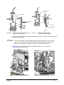
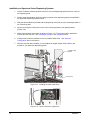
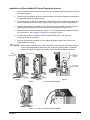
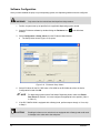
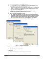
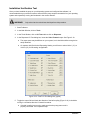
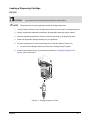
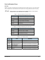
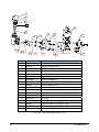
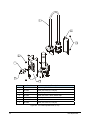
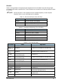
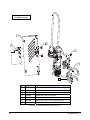
1
DV-7000/DV-8000 Series
®
Heli-Flow Pump
Owner's Manual
NOTICE
This is an Asymtek publication, which is protected by copyright. Original copyright date 2006. No part of this document
may be photocopied, reproduced, or translated to another language without the prior written consent of Asymtek. The
information contained in this publication is subject to change without notice.
Manuals on the Internet
For the convenience of Asymtek customers and field service representatives, copies of Asymtek manuals can be
downloaded from:
http://www.asymtek.com/support/manuals.htm
Contact Us
Asymtek welcomes requests for information, comments, and inquiries about its products. Please contact us using the
information below:
Headquarters
2762 Loker Avenue West
Carlsbad, CA 92010-6603
USA
Toll Free:
Tel:
1-800-ASYMTEK (1-800-279-6835)
+1-760-431-1919
Fax:
+1-760-431-2678
E-mail:
[email protected]
Website:
www.asymtek.com
USA:
1-800-ASYMTEK (1-800-279-6835)
Other regions:
www.asymtek.com/support.htm
Technical Support
Trademarks
®,
®
®
®
®
®
®
Asymtek Century , Millennium , Spectrum , DispenseMate , Fluidmove , and Heli-flow are registered trademarks of Asymtek.
Axiom ™ is a trademark of Asymtek.
®
®
Microsoft , Windows , and Windows XP
P/N 7212372, Revision A
®
are registered trademarks of Microsoft Corporation.
©2006
Table of Contents
Table of Contents ........................................................................................................................................1
1
Introduction ..........................................................................................................................................1
Overview ................................................................................................................................................1
DV-7000 .................................................................................................................................................1
Dispensing Systems.......................................................................................................................1
DV-7000 Configurations.................................................................................................................1
DV-7000 Specifications..................................................................................................................1
DV-7000 Features..........................................................................................................................2
DV-8000 .................................................................................................................................................3
Dispensing Systems.......................................................................................................................3
DV-8000 Series Configurations .....................................................................................................3
DV-8000 Series Features...............................................................................................................4
2
Safety ....................................................................................................................................................5
Overview ................................................................................................................................................5
Intended Use..........................................................................................................................................5
Safety of Personnel................................................................................................................................6
Material Safety ...............................................................................................................................6
Preventing Equipment and Workpiece Damage....................................................................................6
3
Installation ............................................................................................................................................7
Overview ................................................................................................................................................7
Installing the Pump ................................................................................................................................7
Installation on Century Series Systems .........................................................................................8
Installation on M-2000 Series or X-1000 Series Systems ...........................................................10
Installation on Spectrum Series Dispensing Systems .................................................................12
Installation on DispenseMate 550 Series Dispensing Systems...................................................13
Software Configuration ........................................................................................................................14
Installation Verification Test .................................................................................................................16
4
Operation ............................................................................................................................................18
Overview ..............................................................................................................................................18
Theory of Operation .............................................................................................................................18
Pump Adjustments...............................................................................................................................18
Motor Speed.................................................................................................................................18
Air Pressure .................................................................................................................................19
Software Parameters ...................................................................................................................19
Assembling a Dispensing Cartridge.....................................................................................................19
Loading a Dispensing Cartridge ..........................................................................................................21
DV-7000 .......................................................................................................................................21
DV-8000 .......................................................................................................................................22
Installing/Changing a Fluid Syringe .....................................................................................................24
Installing a Syringe of Conditioning Fluid (Solder Paste Applications Only)................................24
Installing/Changing a Syringe of Production Fluid .......................................................................26
Priming the Pump ................................................................................................................................27
Non Solder Paste Applications ....................................................................................................27
Solder Paste Applications ............................................................................................................29
Valve Offsets........................................................................................................................................30
DV-7000 Optional Configuration..........................................................................................................31
5
Maintenance and Service ..................................................................................................................32
Overview ..............................................................................................................................................32
Safety First...........................................................................................................................................32
Recordkeeping.....................................................................................................................................32
Introduction
1
Calibration and Adjustment..................................................................................................................32
Parts Ordering Information...................................................................................................................32
Preventive Maintenance ......................................................................................................................32
Cleaning the Pump ..............................................................................................................................33
DV-7000 .......................................................................................................................................33
DV-8000 .......................................................................................................................................35
Removing the Pump from the Dispensing System ..............................................................................37
Pump Assembly and Disassembly ......................................................................................................38
6
Troubleshooting.................................................................................................................................39
Overview ..............................................................................................................................................39
Safety First...........................................................................................................................................39
Troubleshooting the Pump...................................................................................................................39
7
Specifications.....................................................................................................................................41
Overview ..............................................................................................................................................41
Safety First...........................................................................................................................................41
Specifications.......................................................................................................................................41
8
Parts Replacement.............................................................................................................................42
Overview ..............................................................................................................................................42
Safety First...........................................................................................................................................42
Parts Ordering Information...................................................................................................................42
Placing Your Order.......................................................................................................................42
Warranty.......................................................................................................................................42
Return Material Authorization ......................................................................................................42
Unpacking and Inspecting Replacement Parts....................................................................................42
Parts List/Exploded Views ...................................................................................................................43
DV-7000 .......................................................................................................................................43
DV-8000 .......................................................................................................................................47
Cartridges ............................................................................................................................................55
2
Introduction
1
Introduction
Overview
The DV-7000 Series and DV-8000 Series Heli-Flow Pumps are rotary, positive displacement auger valves.
Each valve has a closed-loop, servo-controlled motor with encoder feedback that can reverse to create a
clean fluid cutoff. The DV-7000/DV-8000 pumps are designed and exclusively manufactured by Asymtek to
meet high-volume production requirements.
"
NOTE
The terms pump and valve are synonymous in this manual.
DV-7000
The DV-7000 (Figure 1-1) can be used as a floating head pump for dispensing dots, or as a standard pump
for dispensing lines and/or patterns. The DV-7000 is available in a luer- or footed-needle design with
interchangeable cartridges, allowing the pump to work with several different fluid types. The DV-7000 has a
hardened auger for use with filled epoxy materials and features a high flow rate.
Dispensing Systems
•
X-1010 Axiom™ SMT Dispensing System
•
M-2010 Millennium® Ultra High Speed SMT Dispensing System
•
C-718 Century® Precision SMT Dispensing System
•
D-550 DispenseMate® Series Dispensing System
•
S-820 Spectrum® Precision Batch Dispensing System
DV-7000 Configurations
Table 1-1 identifies all currently available standard configurations for the DV-7000 Series pump. Contact
Asymtek or your local distributor for other configurations that may better suit your application.
Table 1-1 DV-7000 Standard Configurations
Model
Description
Applications
DV-7222-SF1
Footed needle cartridge
Surface Mount Adhesive, Solder Paste, Silver Epoxy
DV-7222-SL1
Luer-lock needle cartridge
Surface Mount Adhesive, Solder Paste, Silver Epoxy
DV-7223-CP-SLP
Luer-lock needle cartridge
Silver Epoxy, Types 3 and 4 Solder Pastes
DV-7223-CP-0LP
Luer-lock needle cartridge
Types 5 and 6 Solder Pastes
DV-7321-CL8
Luer-lock needle cartridge
Dam Writing
DV-7322-CL8
Luer-lock needle cartridge
Glob Top, Encapsulation
DV-7331-CL8
Luer-lock needle cartridge
Lid Seal
DV-7000 Specifications
Table 1-2 DV-7000 Specifications
Dimensions
Length: 190-192 mm (7.48 - 7.56 inch)
Width: 33 mm (1.3 inch)
Depth: 72.6 mm (2.86 inch)
Air Pressure
34-552 kPA (5-80 psi, 0.7 - 5.5 bar)
Depending on the fluid, higher viscosities require higher pressures
Motor
Closed-loop control with encoder feedback on the dispensing platform
Introduction
1
DV-7000 Features
The DV-7000 (Figure 1-1) is designed with the following key features:
•
Footed cartridge with a fixed mechanical stand-off nozzle for extremely consistent dots and
increased throughput
•
Luer-cartridge option allows use with a wide range of standard needles
•
Tool-free disassembly of wetted parts for quick and easy cleaning
•
Fast cartridge changeover
•
Cartridges are interchangeable with DV-8000 pumps
•
Closed-loop motor control with encoder feedback ensures high repeatability and precision
dispense control
Fluid Syringe
Motor
Flexible Fluid
Path (rigid path
optional)
Needle
Figure 1-1 DV-7000 (DV-7222-SF1 shown)
2
Introduction
DV-8000
The DV-8000 Heli-Flow® pump (Figure 1-2) features interchangeable cartridges for use in high flow rate
encapsulation and lid seal applications, allowing each pump to work with several different fluid types. The
DV-8000 has a fixed head design for use with high-viscosity fluids and high flow rate for fast dam writing.
Typical applications for the DV-8000 include thermal grease, silver epoxy, and lid seal and dam materials.
Dispensing Systems
•
X-1020 Axiom™ Dispensing System
•
M-2020 Millennium® Ultra High Speed Dispensing System
•
S-820 Spectrum® Precision Batch Dispensing System
•
D-550 DispenseMate® Series Dispensing System
DV-8000 Series Configurations
Table 1-3 identifies all currently available standard configurations for the DV-8000 Series pump. Contact
Asymtek or your local distributor for other configurations that may better suit your application.
Table 1-3 DV-8000 Standard Configurations
Model
Description
Applications
DV-8222 16-pitch carbide
2.5 mm diameter feedscrew
Small dots on DV-8000 pumps; low flow rate
DV-8322 16-pitch carbide
3.5 mm diameter feedscrew
Encapsulants
DV-8321 8-pitch carbide
3.5 mm diameter feedscrew
General purpose encapsulation
DV-8331 8-pitch carbide
3.5 mm diameter feedscrew
DV-8442 16-pitch carbide
4.5 mm diameter feedscrew
High flow rates
Highest flow rate, for high flow rate dams and
lid seal
Table 1-4 DV-8000 Specifications
Dimensions
Length: 190-192 mm (7.48 - 7.56 inch)
Width: 33 mm (1.3 inch)
Depth: 72.6 mm (2.86 inch)
Air Pressure
34-552 kPA (5-80 psi, 0.7 - 5.5 bar)
Depending on the fluid, higher viscosities require higher pressures
Motor
Closed-loop control with encoder feedback on the dispensing platform
Flow Rate
Range
Flow rate depends on fluid, needle, valve speed, and syringe pressure
Minimum volume displacement allows pump to dispense dots smaller than 0.5 mm in
diameter
Maximum flow rate capability for damming material is well over 100 mg/s (viscosity 1 M
centipoises, specific gravity 1.76)
Introduction
3
DV-8000 Series Features
The DV-8000 is designed with the following key features:
•
Ideal for high-speed dams and lines of encapsulants, silver epoxy, lid seal, and thermal grease
•
Tool-free disassembly of wetted parts for quick and easy cleaning
•
Fast cartridge changeover
•
Cartridges are interchangeable with DV-7000 pumps
•
Closed-loop motor control with encoder feedback ensures high repeatability and precision
dispense control
•
Long-life carbide cartridges
•
Powerful 11-watt motor and two gear box options (19:1 standard and 4:1 for high flow
applications) are designed for use with thick fluids
Motor (4.4:1 or
19:1 gear ratio)
Fluid Syringe
Rigid Fluid Path
Needle (Luer)
Figure 1-2 DV-8000 (DV-8222-CL1 shown)
4
Introduction
2
Safety
Overview
This section describes the precautions to be taken to promote safety of personnel and prevent unnecessary
damage to your DV-7000 or DV-8000 Series Heli-Flow Pump and valuable workpieces.
WARNING!
CAUTION!
Unsafe equipment conditions can result in personal injury or property damage.
Failure to properly operate and maintain the system in accordance with this manual
may jeopardize the built-in safety features.
CAUTION!
"
NOTE
The DV-7000 and DV-8000 pumps are precision instruments. Follow all precautions
and use care when installing, operating, or performing maintenance/service. Failure
to do so may cause damage to the pump. Only trained personnel should perform
pump installation, operation, maintenance, and service.
Safety is considered a joint responsibility between the original equipment manufacturer
(Asymtek) and the end-user (owner). In addition to those recommended in this manual,
safety precautions and practices should be in accordance with local laws and regulations.
Intended Use
The DV-7000 and DV-8000 pumps are intended for use as described in this manual. Using the pump for
other purposes is not recommended. Some examples of pump misuse include:
•
Using incompatible materials
•
Making unauthorized modifications
•
Removing or bypassing safety guards or interlocks
•
Using incompatible or damaged parts
•
Using unapproved auxiliary equipment
•
Operating equipment in excess of maximum ratings
WARNING!
Safety
Unsafe equipment conditions can result in personal injury or property damage.
Failure to adhere to safety warnings and precautions could result in serious bodily
harm to the user.
5
Safety of Personnel
•
Only trained personnel should be permitted to perform installation, operation, maintenance, and
troubleshooting procedures on the DV-7000/DV-8000 Series pumps.
•
Before performing maintenance or service on the DV-7000/DV-8000 pumps, position it at the
front of the dispensing chamber. This will provide easy access to components and limit exposure
to hazardous areas.
•
Immediately push the red Emergency Machine Off (EMO) button on your dispensing system if
personnel are in danger.
•
Do not touch the moving parts while the dispensing system is operating.
•
Remove the DV-7000/DV-8000 pump completely from the dispensing system and allow the
heated parts to cool before cleaning or performing maintenance.
•
Relieve pneumatic pressure before adjusting or servicing pressurized components.
Material Safety
•
Follow Material Safety Data Sheet (MSDS) recommendations for the proper handling, cleanup,
and disposal of hazardous materials.
•
Know the MSDS recommendations for treatment of injury resulting from exposure to hazardous
materials.
•
When working with multiple fluids, refer to the MSDS to ensure the materials are compatible.
Preventing Equipment and Workpiece Damage
6
•
Immediately push the EMO button on the dispensing system if the dispensing system, pump, or
a workpiece is in danger of being damaged.
•
Use standard Electrostatic Discharge (ESD) precautions when working near sensitive
components. Always wear a grounding strap and connect it to the ESD ground before handling
workpieces and equipment.
•
Perform all recommended DV-7000/DV-8000 maintenance procedures at the suggested
intervals.
•
Immediately contain and clean up any caustic or conductive fluid spills as recommended in the
material manufacturer’s MSDS.
•
If fluid gets into internal portions of the DV-7000/DV-8000, immediately contact Asymtek
Technical Support.
•
Use only replacement parts that are designed for use with the original equipment. See the Parts
Replacement section for a list of available parts and part numbers.
Safety
3
Installation
Overview
This section includes DV-7000/DV-8000 installation instructions for the Century, Millennium M-2000, Axiom,
Spectrum, and DispenseMate Series Dispensing Systems.
"
NOTE
For more information, refer to the manual for your particular dispensing system.
This section covers the following topics:
•
Installing the Pump
•
Software Configuration
•
Installation Verification Test
Installing the Pump
If your DV-7000/DV-8000 pump was factory installed, you do not need to perform this procedure. Proceed
with “Installing/Changing a Fluid Syringe” in the Operation section.
"
NOTE
The installation instructions below do not include installation of an upgrade kit. If the pump is
installed on a system that requires an upgrade kit, contact Asymtek Technical Support for
additional information.
WARNING!
CAUTION!
Before installing the pump, the dispensing system must be completely powered
down. Lock out and tag out power to the dispensing system to prevent accidental
restoration of power during pump installation. Refer to the manual for your particular
dispensing system for instructions.
WARNING!
The procedures in this section should be performed by trained personnel only.
Tools and Materials Needed
"
•
2 mm Hex Key
•
Phillips Head Screwdriver
•
3 mm Hex Key
•
Valve bracket
•
4 mm Hex Key
•
Height Sensor and Bracket (application dependent)
NOTE
Installation
Prior to installation, use the software or dispensing system position controls to move the
dispensing head to the front center of the dispensing area. Perform a service shutdown as
specified in the applicable dispensing system manual. Remove any valve currently installed
on the dispensing head. If the valve bracket installed is incompatible with the DV-7000/DV8000, remove it and the Height Sensor (if present). Refer to the installation/removal
procedures in the applicable valve manual if necessary.
7
Installation on Century Series Systems
"
NOTE
Illustrations in this section show the DV-7000, but installation instructions also apply to
DV-8000 Series pumps.
1.
Use the position controls to move the dispensing head to the front center of the dispensing area.
2.
Perform a service shutdown and lock out/tag out power to the dispensing system as specified in
the applicable dispensing system manual.
3.
Slide the valve into the valve bracket (Figure 3-1).
4.
Use a 4 mm hex key to tighten the locking screw on the side of the valve bracket.
! The valve should be tightly held by the bracket.
Valve Bracket
Figure 3-1 Attaching the Valve Bracket (Century Series System)
"
8
NOTE
If you will be using a Height Sensor, proceed with Step 5. If not, skip to Step 7.
5.
Use a 3 mm hex key to attach the height sensor bracket to the valve bracket (Figure 3-2).
6.
Use a Phillips head screwdriver to attach the height sensor to the height sensor bracket
(Figure 3-3).
Installation
Height Sensor
Bracket
Valve Bracket
Height Sensor
Bracket
Height Sensor
Figure 3-2 Attaching the Height Sensor Bracket
7.
Slide the pump (with Height Sensor, if installed) into the valve mounting plate (Figure 3-4).
!
8.
Position the valve bracket on the mounting plate so that when the pump is installed it will not
collide with components when moving around the dispensing area.
While holding the valve bracket in place, use a 2 mm hex key to tighten the setscrews on the side
of the valve mounting plate.
!
9.
The valve bracket should be tightly held in the mounting plate.
Connect the pump power cord and Height Sensor power cord (if a Height Sensor is present) to
the dispensing head bulkhead.
Figure 3-4 Mounting the Valve (Century)
"
10.
Installation
Figure 3-3 Attaching the Height Sensor (Century)
NOTE
Figure 3-5 Valve Electrical Connections (Century)
Figure 3-5 shows connections on a typical Century System. For systems with a
Dual-Action Dispensing Head, refer to the applicable manual.
Configure the Fluidmove software for the DV-7000/DV-8000 valve. See "Software
Configuration" later in this section.
9
Installation on M-2000 Series or X-1000 Series Systems
"
NOTE
Illustrations in this subsection show the DV-8000, but installation instructions also apply to
DV-7000 Series Pumps.
1.
Use the position controls to move the dispensing head to the front center of the dispensing area.
2.
Perform a service shutdown and lock out/tag out power to the dispensing system as specified in
the applicable dispensing system manual.
3.
Use a 3 mm hex key to attach the valve bracket to the valve mounting plate (Figure 3-6).
Position the valve bracket on the mounting plate so that when the pump is installed it will not
collide with components when moving around the dispensing area.
!
Valve
Mounting
Plate
Bracket Mounting
Screws
Valve Bracket
Figure 3-6 Attaching the Valve Bracket
(M-2000 shown)
4.
Slide the pump into the valve bracket (Figure 3-7).
5.
Use a 4 mm hex key to tighten the locking screw on the side of the valve bracket.
!
"
10
Figure 3-7 Mounting the Valve (M-2000 shown)
The pump should be tightly held by the bracket.
NOTE
If you will be using a height sensor, proceed with Step 6. If not, skip to Step 8.
6.
Use a 3 mm hex key to attach the height sensor bracket to the valve bracket (Figure 3-8).
7.
Use a Phillips head screwdriver to attach the height sensor to the height sensor bracket
(Figure 3-9).
Installation
Height Sensor
Bracket
Valve Bracket
Height Sensor
Bracket
Height Sensor
Figure 3-8
8.
"
Attaching the Height Sensor Bracket
(M-2000, X-1000 Systems)
Location of the power connections depends on the dispensing system. Figure 3-10 and
Figure 3-11 show typical connections on M-2000 and X-1000 dispensing systems. For
systems with a Dual-Action Dispensing Head, refer to the applicable manual.
Configure the Fluidmove software for the DV-7000/DV-8000 valve. See "Software
Configuration" later in this section.
Figure 3-10 Valve Connections (M-2000)
Installation
Attaching the Height Sensor
(M-2000, X-1000 Systems)
Connect the pump power cord and height sensor power cord (if a height sensor is present) to the
dispensing head bulkhead.
NOTE
9.
Figure 3-9
Figure 3-11 Valve Connections (X-1000)
11
Installation on Spectrum Series Dispensing Systems
1.
Use the Fluidmove software position controls to move the dispensing head to the front center of
the dispensing area.
2.
Perform a service shutdown and lock out/tag out power to the dispensing system as specified in
the applicable dispensing system manual.
3.
Slide the dovetail bracket (included with the dispensing valve) into the valve mounting bracket on
the Z-axis face plate.
4.
Secure by turning the locking lever on the valve mounting bracket to the upward position
(Figure 3-12).
5.
Make valve electrical connections as shown in Figure 3-13. The syringe must be installed to
connect the clear fluid line. See "Installing a Syringe" in the Operation section.
6.
Configure the Fluidmove software for the DV-7000/DV-8000 valve. See "Software
Configuration" later in this section.
7.
After the valve has been installed, you must adjust the Height Sensor Probe. Refer to the
manual for your particular dispensing system.
Valve Mounting
Bracket
Locking Lever
Figure 3-12 Installing the Valve (Spectrum)
Figure 3-13 Valve Connections (Spectrum)
12
Installation
Installation on DispenseMate 550 Series Dispensing Systems
"
1.
Use the Fluidmove software position controls to move the dispensing head to the front center of
the dispensing area.
2.
Perform a service shutdown and lock out/tag out power to the dispensing system as specified in
the applicable dispensing system manual.
3.
Loosen the six (6) screws on the Z-axis face plate (Figure 3-14A) and slide the face plate up so
that it is flush with the Z-axis extrusion (Figure 3-14B). Tighten the screws on the face plate.
4.
Slide the dovetail bracket (included with the valve) into the valve mounting bracket. Secure by
tightening the socket head cap screw on the valve mounting bracket (Figure 3-14C).
5.
Make electrical connections as shown in Figure 3-15. The syringe must be installed to connect
the clear fluid line. See "Installing a Syringe" in the Operation section.
6.
Configure the Fluidmove software for the DV-7000/DV-8000 valve. See "Software
Configuration" later in this section.
7.
After the valve has been installed, you must adjust the Height Sensor Probe. Refer to the
DispenseMate User Guide.
NOTES
When using the DV-7000 valve, make sure that the Valve Selector (U27) switch, located
on the main board inside the electronics pan, is set to the proper position. The default
setting is DV-8000. For detailed information, refer to the DispenseMate User Guide.
Z-axis Extrusion
Z-axis
Face Plate
Valve
Mounting
Bracket
Socket Head
Cap Screw
Figure A
Figure B
Figure C
Figure 3-14 Installing the Valve (DispenseMate)
Figure 3-15 Valve Connections (DispenseMate)
Installation
13
Software Configuration
Once you have installed the pump on your dispensing system, the dispensing software must be configured.
WARNING!
Only trained service technicians should perform this procedure.
1.
Perform a system start-up as specified in the applicable dispensing system manual.
2.
Start the Fluidmove software by double-clicking the Fluidmove icon
desktop.
3.
Select Configuration > Setup Valves from the Fluidmove Main Window.
!
on the Windows
The Setup Valves screen (Figure 3-16) opens.
Figure 3-16 Fluidmove Setup Valves
4.
Select DV-Series for the DV-7000 valve or DV-8000 for the DV-8000 valve from the Active
Configuration list and click OK.
"
5.
NOTE
If the DV-7000/DV-8000 is equipped with a floating head, perform steps a through e. If not, skip
to Step 6.
CAUTION!
14
For dispensing systems with a Dual-Action Dispensing Head, make sure Enable
Dual Valves is checked. You must configure the appropriate valve position (Valve 1
or Valve 2).
Enabling this feature on a valve that is not equipped with a floating head could result
in damage to the valve and to the workpiece.
Installation
a. In the Setup Valves dialog box, click on Edit (Figure 3-16).
b. In the Settings dialog box, click on the Settings tab and click on the radio button next to
Constant syringe pressure during dispensing (Figure 3-17).
!
c.
Activating this feature means that a constant supply of air pressure will be applied to the
syringe as opposed to the air toggling ON and OFF as needed. A constant air supply
can result in more a consistent dot size.
Click on the Floating Head tab and click in the box next to Enable Floating Head. A
checkmark in the box indicates the feature is enabled (Figure 3-17).
d. Enter a value for the Floating Head Z Overtravel.
!
The “Floating Head Z Overtravel” is a Z-axis value that determines how far below the
programmed dispensing height the dispensing head will travel in search of the substrate.
This feature ensures a consistent dispensing height even if the workpiece is warped.
The maximum value is 0.08-inch (2 mm). Typically, 0.04-inch (1 mm) is sufficient.
e. Click on OK to accept the new settings and close the Settings dialog box.
Figure 3-17 Enabling the Floating Head
6.
In the Setup Valves dialog box, click on OK.
! You will be prompted to restart Fluidmove.
7.
Click on Yes
!
Installation
Fluidmove will restart and you will be prompted to run Valve Offsets.
15
Installation Verification Test
Once you have installed the pump on your dispensing system and configured the software, it is
recommended that you perform this test to ensure that the pump accepts commands from your operating
system and responds by moving the feedscrew in the correct direction.
WARNING!
Only trained service technicians should perform this procedure.
1. Start Fluidmove.
2. In the Main Window, click on Tools.
3. In the Tools Window, click on I/O Test and then click on Dispenser.
4. In the Dispenser I/O Test dialog box, locate the Valve Forward output. See Figure 3-18.
! The output name may be different on your system, but it should be similar enough to be
easily identified.
! On systems with Dual-Action Dispensing Heads, you will have to select Valve 1 (V1) or
Valve 2 (V2) for I/O testing, as applicable.
Figure 3-18 FmNT I/O Test Dialog Box (typical)
5. Toggle the output ON and check the direction of the ball coupling (Figure 3-19). It should be
turning in a clockwise direction if viewed from above.
! If the ball coupling is not turning, make sure that the pump power cord is
properly connected. Then repeat this step.
16
Installation
6. Toggle the output OFF and make sure that the ball coupling stops turning.
7. In the Dispenser I/O Test dialog box, locate the Valve Reverse output. See Figure 3-18.
! The output name may be different on your system, but it should be similar enough to be
easily identified.
! On systems with Dual-Action Dispensing Heads, you will have to select Valve 1 (V1) or
Valve 2 (V2) for I/O testing, as applicable.
8. Toggle the output ON and check the direction of the ball coupling. It should be turning in a
counterclockwise direction if viewed from above.
! If the ball coupling is not turning, make sure that the pump power cord is
properly connected. Then repeat this step.
9. Toggle the output OFF and make sure that the ball coupling stops turning.
Ball
Coupling
DV-7000
Ball
Coupling
DV-8000
Figure 3-19 Ball Coupling Locations
Installation
17
4 Operation
Overview
This section covers the following topics:
•
Theory of Operation
•
Installing/Changing a Fluid Syringe
•
Pump Adjustments
•
Priming the Pump
•
Assembling a Dispensing Cartridge
•
Valve Offsets
•
Loading a Dispensing Cartridge
•
DV-7000 Optional Configuration
Theory of Operation
The DV-7000 and DV-8000 pumps use the following mode of operation:
1.
Air pressure, which can be configured to remain constant or to toggle ON and OFF with the
pump motor, causes fluid in a syringe to flow into contact with the pump feedscrew. The
feedscrew is held in a cartridge.
2.
The pump motor turns the feedscrew and shears the fluid.
3.
The shear force drives fluid down the threads of the feedscrew and through the dispensing
needle at the end of the cartridge.
4.
Fluid is dispensed onto the workpiece.
The fluid viscosity (resistance to flow), size of the needle opening, geometry of the feedscrew, and the motor
speed determine the quantity of fluid dispensed.
Pump Adjustments
You can optimize the performance of the pump by changing various settings, such as motor speed and air
pressure. Software parameters can also be changed to meet your particular application requirements.
CAUTION!
Only trained service technicians should perform pump settings adjustments.
Motor Speed
Pump motor speed is a crucial factor in the dispensing process. Applications Engineers must consider
dispensing system model, fluid properties, needle size, and substrate when determining the optimum pump
speed for your application.
On systems with front control panels (M-600 Series, Century Series), or systems running FMW, manual
speed controls control the speed of the pump motor. Refer to the manual for your particular dispensing
system for help locating the speed controls.
On M-2000, X-1000, Spectrum, and DispenseMate Series systems and/or systems running FmNT/FmXP,
speed control is integrated in the software. To locate the speed controls in Fluidmove, click on
Configuration > Setup Valves in the Main Window. Click on Edit in the Setup Valves dialog box and select
the Settings tab. Refer to the Fluidmove User Guide or Online Help for more information.
18
Operation
Air Pressure
Air pressure is used to move the material from the syringe to the feedscrew. The greater the pressure, the
faster the material reaches the feedscrew. However, excessive air pressure can be detrimental to the
dispensing process. Refer to the Specifications section for recommended air pressure settings.
Software Parameters
Refer to the Fluidmove User Guide or Online Help for detailed explanations of line and dot parameters.
Assembling a Dispensing Cartridge
CAUTION!
Only trained service technicians should perform this procedure.
Tools and Materials Needed
•
1/4-inch Wrench
•
Dispensing Needle (application specific)
•
Cartridge Kit
•
Seal Insertion Tool Set (P/N 197004)
1.
Verify that all parts of the cartridge are clean. If not, clean in accordance with “Cleaning the
Pump” in the Maintenance and Service section.
2.
Install the seal into the cartridge body as follows (see Figure 4-1):
"
NOTE
If the cartridge does not have a seal, skip to Step 3.
a. Place the seal, spring side up, onto the seal insertion tool.
b. Place the seal guide onto the cartridge body.
c.
Press the seal into the cartridge body through the seal guide.
d. Remove the seal insertion tool and then the seal guide.
!
3.
The seal should remain inside the cartridge body.
Gently press the lower bearing down on top of the cartridge body (Figure 4-2).
!
This will seat the seal (if present) to the proper depth in the cartridge.
4.
Insert the feedscrew/thrust collar assembly into the top of the cartridge body until the thrust collar
sits flush on top of the lower bearing.
5.
Install a needle of the appropriate size into the needle retainer and thread the retainer into the
end of the cartridge body.
!
6.
Using a 1/4-inch wrench, install the cartridge fitting into the cartridge body.
!
Operation
Do not over-tighten the needle retainer. Finger-tight is sufficient.
Do not over-tighten the fitting or the plastic threads may strip.
19
Thrust Collar
Feedscrew
Cartridge Body
Seal Guide Tool (P/N
196630)
Lower
Bearing
Seal
(spring side up)
Cartridge
Body
Seal Insertion Tool (P/N
196629)
Cartridge Fitting
(Luer)
Needle
(Luer)
Needle
Retainer
Figure 4-1 Installing a Cartridge Seal
20
Figure 4-2 Dispensing Cartridge Exploded
Operation
Loading a Dispensing Cartridge
DV-7000
CAUTION!
"
NOTE
Only trained service technicians should perform this procedure.
This procedure is for a pump already mounted on the dispensing head.
1.
Use the position controls to move the dispensing head to the front center of the dispensing area.
2.
Perform a production shutdown as specified in the applicable dispensing system manual.
3.
Open the dispensing system door or hatch, and locate the pump on the dispensing head.
4.
Obtain the appropriate cartridge assembly for your application.
5.
Push the cartridge into the valve body making sure to align the guide pin (Figure 4-3).
!
6.
You will hear the cartridge release lever click as the cartridge snaps into place.
Install the fluid syringe, fittings, and feed tube as specified in “Installing/Changing a Fluid
Syringe” later in this section.
Figure 4-3 Cartridge Loading: DV-7000
Operation
21
DV-8000
CAUTION!
"
NOTE
Only trained service technicians should perform this procedure.
This procedure is for a pump already mounted on the dispensing head.
1.
Use the position controls to move the dispensing head to the front center of the dispensing area.
2.
Perform a production shutdown as specified in the applicable dispensing system manual.
3.
Open the dispensing system door or hatch and locate the pump on the dispensing head.
4.
Obtain the appropriate cartridge assembly for your application.
5.
Push in the red clutch lock release and rotate the clutch cap to the right (counterclockwise) one
complete turn (Figure 4-4).
Figure 4-4 Cartridge Loading: DV-8000
6.
Pull out the blue cartridge release lever and rotate it forward toward the front of the pump until it
is in a horizontal position.
7.
Insert the cartridge into the valve body making sure to align the guide pin with the slot.
8.
While holding the cartridge in place, pull out the blue cartridge release lever and rotate it upward
until it is in a vertical position.
!
22
This will lock the cartridge in place.
Operation
9.
Apply the proper bearing preload by pressing the red clutch lock release while lightly rotating the
clutch cap two or three times to the left (clockwise) until the clutch engages the cartridge. See
Figure 4-5.
!
All that is needed to turn the clutch cap is a very light but even touch with your thumb and
index finger. Do not apply radial pressure while turning the clutch cap or the friction on the
threads will result in an improper preload setting. You will feel or hear a click when the clutch
has reached its set preload.
CAUTION!
DO NOT remove or attempt to adjust the setscrews in the clutch cap or serious
damage to the pump will result.
10.
After the clutch has reached its set preload, verify that there is no axial movement between the
cartridge and the valve body. See Figure 4-5. Reset preload if necessary.
11.
Install the fluid syringe, fittings, and 90-degree elbow as specified in “Installing/Changing a Fluid
Syringe” later in this section.
Figure 4-5 Setting the Bearing Preload
Operation
23
Installing/Changing a Fluid Syringe
Installing a Syringe of Conditioning Fluid (Solder Paste Applications Only)
When using the DV-7000/DV-8000 valve to dispense solder paste, you should install a syringe of
conditioning fluid and prime the pump in between cleanings. See "Solder Paste Applications" later in this
section. You may leave the conditioning fluid installed, until you are ready to install the syringe of solder
paste.
WARNING!
Refer to the Material Safety Data Sheet (MSDS) for information on safety, handling,
and disposal for all fluids and materials before use. All fluids and materials must be
disposed of according to local regulations. Wear personal protective equipment
(PPE) when performing this procedure to prevent contact with caustic chemicals.
CAUTION!
Only trained service technicians should perform this procedure.
Tools and Materials Needed
24
•
Syringe of Conditioning Fluid
•
Personal Protective Equipment
•
Syringe Receiver Head and Air Hose
•
Feed Tube and Fittings
1.
Install the fittings and the feed tube on the pump as required by your application (Figure 4-6).
!
For most applications using the DV-7000, a flexible feed tube attaches to one barbed fitting
threaded into the syringe bracket and another threaded into the dispensing cartridge.
!
For line and pattern applications using the optional configuration DV-7000, a rigid feed tube
assembly threads into the syringe at one end (using a threaded Luer fitting) and the cartridge
fitting at the other end. The syringe bracket is not installed.
!
For applications using the DV-8000, a rigid feed tube assembly threads into the syringe at
one end (using a threaded Luer fitting) and the cartridge fitting at the other end.
2.
Obtain a syringe containing conditioning fluid and remove the cap from the end.
3.
Slide the syringe down through the syringe clip and screw it into the syringe fitting.
4.
Screw a clean receiver head onto the top of the syringe.
5.
Connect the syringe air hose to the receiver head and the blue FLUID AIR connector on the
dispensing head bulkhead.
6.
Perform a dispensing system start-up as specified in the applicable dispensing system manual.
7.
Prime the pump. See “Priming the Pump” later in this section.
Operation
1
1
2
2
3
3
4
4
5
6
DV-8000
7
8
9
DV-7000
Item
10
11
Description
1
Syringe Air Hose (P/N 40-3510)
2
Receiver Head (P/N SA-603, SA-606, SA-610, or SA-635)
3
Syringe
4
Syringe Clip
5
Syringe Fitting (P/N 42-0229)
6
Syringe Bracket (P/N 02-0093-00, not used with rigid Feed Tube)
7
Flexible Feed Tube (42-0014)
8
Barbed Cartridge Fitting (P/N 42-0228)
9
Luer Elbow Assembly (P/N 63-0064-00)
10
Luer Adapter (P/N 42-0225)
11
Luer Cartridge Fitting (Luer – P/N 42-0028)
Figure 4-6 Installing/Changing a Syringe
Operation
25
Installing/Changing a Syringe of Production Fluid
WARNING!
Refer to the Material Safety Data Sheet (MSDS) for information on safety, handling,
and disposal for all fluids and materials before use. All fluids and materials must be
disposed of according to local regulations. Wear personal protective equipment
(PPE) when performing this procedure to prevent contact with caustic chemicals.
CAUTION!
Only trained service technicians should perform this procedure. When changing
syringes, avoid introducing air into the fluid path. Air in the fluid path will adversely
affect dispensing performance.
Tools and Materials Needed
"
•
Clean Cloth and Solvent (for spills)
• New Feed Tube and Fittings (if changing fluid)
•
1/4-inch Wrench or Pliers (as needed)
• Appropriate Personal Protective Equipment
•
Syringe of Fluid to be Dispensed
NOTE
1.
Use the position controls to move the dispensing head to the front center of the dispensing area.
2.
Perform a production shutdown as specified in the applicable dispensing system manual.
!
If there is no syringe installed, skip to Step 6.
3.
Disconnect the syringe air hose from the FLUID AIR connector on the dispensing head bulkhead.
4.
Remove the syringe receiver head from the empty syringe and unscrew the depleted syringe
from its fitting.
!
If the fitting turns with the syringe, use a small wrench or pair of pliers (as applicable) to hold
the fitting while unscrewing the syringe.
5.
Remove the syringe and discard it in accordance with local regulations.
6.
Obtain a new syringe and inspect the fluid for voids. If voids are present, obtain another syringe.
7.
Remove the syringe cap and hold the syringe tip-side-down to allow the fluid to completely fill the
syringe tip.
8.
Slide the new syringe down through the syringe clip and screw it onto the syringe fitting.
!
9.
26
If changing fluid types, you must first clean and prime the pump in accordance with
“Cleaning the Pump” in the Maintenance section.
There should be no fluid voids at the top of the syringe fitting. If any material seeps over the
fitting, clean the fitting with a cloth and recommended solvent.
Screw the receiver head onto the top of the new syringe.
10.
Connect the syringe air hose to the FLUID AIR connector on the dispensing head bulkhead.
11.
Perform a dispensing system start-up as specified in the applicable dispensing system manual.
Operation
Priming the Pump
The purpose of priming is to initiate fluid flow into the pump and to eliminate any air in the fluid path. Priming
is necessary after any of the following has occurred:
•
Initial setup of the pump during installation
•
Disassembly/cleaning of the dispensing cartridge and/or fittings
•
Syringe Change
This subsection contains priming procedures for both solder paste and non-solder paste applications.
WARNING!
Refer to the Material Safety Data Sheet (MSDS) for information on safety, handling,
and disposal for all fluids and materials before use. All fluids and materials must be
disposed of according to local regulations. Wear personal protective equipment
(PPE) when performing this procedure to prevent contact with caustic chemicals.
Non-Solder Paste Applications
Tools and Materials Needed:
•
Syringe of Production Fluid
•
Plastic Purge Cup (P/N 58-0030)
•
Dispensing Needle (application specific)
•
Appropriate Personal Protective Equipment
CAUTION!
"
NOTE
Only trained service technicians should perform this procedure.
This procedure assumes that a clean dispensing cartridge and needle are installed. If not
clean, refer to “Cleaning the Pump” in the Maintenance section.
1.
Perform a dispensing system start-up as specified in the applicable dispensing system manual.
2.
Use the position controls to move the dispensing head directly over the purge station.
3.
Open the dispensing system door/hatch and perform the following:
a. Install a syringe of production-run fluid on the pump. Refer to “Installing/Changing a Fluid
Syringe” earlier in this section.
b. Remove the purge station lid.
c.
If the purge cup contains fluid, remove it and replace with a clean cup.
4.
Close the dispensing system door/hatch.
5.
In the Fluidmove Main Window, click on Run a Program (Figure 4-7).
!
Authorized personnel can also turn the Pump ON and OFF by going to Tools>I/O
Test>Dispenser and toggling the Valve Forward output.
6.
In the Production Window, click on Setup and then double click on Valve-Forward/Reverse.
7.
In the Select Valve dialog box, select the valve you want to prime and click on OK.
!
Operation
On systems with Dual-Action Dispensing Heads, you will have to select Valve 1 (V1) or
Valve 2 (V2), as applicable.
27
8.
In the Valve Forward dialog box click the radio button next to Forward and enter a duration of
120 seconds (2 minutes).
!
The 120-second Valve Forward duration is an estimate of the time necessary for the
production-run fluid to flow completely through the pump and be dispensed in a steady,
unbroken stream. The preferred duration may vary.
!
Pump motor speed should be at your production-run setting.
Figure 4-7 FmNT Valve Forward Screens
9.
Click on the Forward button to start the pump.
10.
After the pump has stopped, check for drooling.
!
11.
If there is no drooling present, proceed to Step 12. If the fluid is still drooling, repeat Steps 8
through 10 until no drooling occurs.
!
12.
28
“Drooling” means that fluid continues to drip from the tip of the needle when the pump is
OFF. If drooling occurs, it means that there is air in the fluid path, or the system air pressure
is set too high.
There should be no drooling of fluid from the needle after the pump has stopped. If drooling
is persistent, refer to the Troubleshooting section.
Open the dispensing system door/hatch, replace the purge cup if necessary, and replace the
purge station lid.
Operation
Solder Paste Applications
Solder Paste applications require a different priming procedure than non-solder paste applications because
of the tendency of the paste to “cold weld” to the feedscrew. This cold welding increases feedscrew wear and
affects dispensing performance.
Tools and Materials Needed
•
Syringe of Solder Paste
•
Appropriate Personal Protective Equipment
•
Syringe of Conditioning Fluid (KC-01)
•
Plastic Purge Cup (P/N 58-0030)
•
Dispensing Needle (application specific)
•
Clean Cloth with recommended Solvent
CAUTION!
"
NOTE
Only trained service technicians should perform this procedure.
This procedure assumes that a clean dispensing cartridge and needle are installed. If not
clean, refer to “Cleaning the Pump” in the Maintenance section.
1.
Perform dispensing system start-up as specified in the applicable dispensing system manual.
2.
Use the position controls to move the dispensing head directly over the purge station.
3.
Open the dispensing system door/hatch and perform the following:
a. Install a syringe of conditioning fluid on the pump. See “Installing/Changing a Fluid Syringe."
b. Remove the Purge Station Lid. If the purge cup contains fluid, remove it and replace with a
clean cup.
4.
Close the dispensing system door/hatch.
5.
In the Fluidmove Main Window, click on Run a Program.
!
"
6.
NOTE
Authorized personnel can also turn the Pump ON and OFF by going to Tools >
I/O Test > Dispenser and toggling the Valve Forward output.
In the Production Window, click on Setup and then double click on Valve - Forward/Reverse
(Figure 4-7).
"
7.
The Fluidmove Production Window opens.
NOTE
On systems with Dual-Action Dispensing Heads, you will have to select Valve 1
(V1) or Valve 2 (V2), as applicable.
In the Valve Forward dialog box click the radio button next to Forward and enter a duration of 60
seconds (1 minute).
!
The 60-second Valve Forward duration is an estimate of the time necessary for the
conditioning fluid to flow completely through the pump and be dispensed in a steady,
unbroken stream. The preferred duration may vary. Pump motor speed should be at your
production-run setting.
8.
Click on the Forward button to start the pump.
9.
After the pump has stopped, check for drooling.
!
Operation
“Drooling” means that fluid continues to drip from the tip of the needle when the pump is
OFF. Drooling occurs because there is air in the fluid path or the air pressure is too high.
29
10.
If there is no drooling present, proceed to Step 11. If drooling persists, refer to the
Troubleshooting section.
11.
When drooling has stopped, open the dispensing system door/hatch, and perform the following:
a. Remove the syringe of conditioning fluid and install a syringe of solder paste.
b. Remove and set aside the needle from the dispensing cartridge.
c.
If the purge cup is full, remove it and replace with a clean purge cup.
12.
Close the dispensing system door/hatch.
13.
Set the pump motor speed to a slow rate (0.5 to 1.0 for M-600 Series Systems, 100 for M-2000
Series Systems, 10 percent on X-1000 Series Systems) to prevent cold welding of the solder
paste during the priming operation.
14.
Set the Valve Forward duration to 180 to 300 seconds (3 to 5 minutes) and click on the Forward
button to start the pump.
!
15.
The Valve Forward duration above is an estimate of the time necessary for the solder paste
to completely purge the conditioning fluid from the pump.
Repeat Step 15 as needed until you can see that all conditioning fluid has been purged into the
purge cup.
!
There should be no drooling of solder paste from the pump after it has stopped.
16.
Open the dispensing system door/hatch and clean any residual solder paste from the end of the
cartridge using a clean cloth and manufacturer-recommended solvent.
17.
Reinstall the needle removed in Step 12 and close the dispensing system door/hatch.
!
18.
Set the Valve Forward duration to 60 seconds (1 minute) minimum and click on the Forward
button to start the pump. Pump motor speed should still be at the slow rate set in Step 13.
!
19.
The needle should still be coated inside with conditioning fluid.
The Valve Forward duration above is an estimate of the time necessary for the solder paste
to flow through the needle and into the purge cup.
Reset the pump motor speed to the rate recommended for your dispensing application.
!
If the needle becomes plugged during the first few minutes of dispensing, do not clean the
dispensing cartridge. Remove the needle and repeat Steps 14 through 19. Make sure the
needle is clean before reattaching it.
Valve Offsets
A Valve Offsets routine in Fluidmove must be performed after any of the following:
•
Initial Valve setup
•
Valve change
•
Height Sensor change or adjustment
This screen-prompted routine identifies and records a Safe Z-Height for dispensing head travel, the XYZ
locations of the Purge Station and Weigh Station (if present), needle, and the substrate height. It also
calibrates the Camera-to-Needle and Needle-to-Height Sensor Probe offsets, if these accessories are
installed on the dispensing system. Refer to the Fluidmove User Guide or Online Help for additional
information.
30
Operation
DV-7000 Optional Configuration
The optional configuration allows the DV-7000 to be used for dispensing lines and/or patterns. The optional
configuration includes the following:
• Luer-compatible Dispensing Cartridge
• Stiffer Spring to stabilize the Floating Head
• Rigid Feed Tube Assembly
The special dispensing cartridge fits into the bottom of the pump in the exact same way as the standard
dispensing cartridge. Operation and maintenance of the special dispensing cartridge is the same as for the
standard dispensing cartridge.
"
NOTE
This optional configuration may be available as a standard feature on the DV-7222-CL1, DV7321-CL8, DV-7322-CL8, and DV-7331-CL8 models. Contact Asymtek for more information.
Tools and Materials Needed
•
No-float Spring Kit (P/N 198537)
• Rigid Feed Tube Assembly (in Consumables Kit)
•
Phillips-head Screwdriver
• Dispensing Cartridge ( in Shipping Kit)
To convert the DV-7000 to optional configuration (see Figure 4-8):
WARNING!
CAUTION!
This procedure MUST NOT be performed while the pump is mounted on the
dispensing head. Only trained service technicians should perform this procedure.
1.
Perform a service shutdown as specified in the applicable dispensing system manual and
remove the pump as specified in “Removing the Pump from the Dispensing System” in the
Maintenance section.
2.
If installed, remove the syringe bracket from the front of the pump.
3.
Install the Luer adapter dispensing cartridge into the valve body as specified in “Loading a
Dispensing Cartridge” earlier in this section.
4.
Use the Phillips-head screwdriver to remove
the two screws on the spring cover plate.
Remove the currently installed spring from
the back of the pump.
5.
Insert the bottom of the No-float Spring (P/N
47-1312) into the back of the pump,
compress the spring, and then slide the top
of the spring into the slot.
6.
Reinstall the spring cover plate and the two
screws.
7.
Install the pump onto the dispensing system.
Refer to the Installation section, if necessary.
Figure 4-8 DV-7000 Optional Configuration
Operation
31
5 Maintenance and Service
Overview
Maintenance of the DV-7000/DV-8000 Heli-Flow Pumps consists of cleaning and priming after dispensing
operations, or between changes of dispensing fluids. Regular cleaning of the pump is essential to
maintaining maximum dispensing performance. This section covers the following topics:
•
Recordkeeping
•
Cleaning the Pump
•
Calibration and Adjustment
•
Removing the Pump from the Dispensing System
•
Parts Ordering Information
•
Pump Assembly and Disassembly
•
Preventive Maintenance
Safety First
It is essential that you follow all safety warnings and consider all safety warning labels when performing the
following maintenance procedures. Refer to the Safety section for specific information.
WARNING!
Before performing any of the maintenance procedures in this section, perform a
service shutdown as described in the applicable dispensing system manual.
WARNING!
Maintenance procedures should be performed by trained personnel only.
Recordkeeping
The type of maintenance performed (such as preventive and parts replacement) should be recorded in
maintenance records for the pump. Dates, part numbers/serial numbers of replaced parts, names of
technicians, and other pertinent data should be recorded.
Calibration and Adjustment
There are no maintenance-related calibration and adjustment requirements for the pump. Before operating
the pump, adjustments are made to dispensing system air pressure and pump motor speed as determined
by your application.
Parts Ordering Information
"
NOTES Part numbers can be found in the illustrations and tables in the Parts Replacement section.
Make sure that the cartridge assembly part numbers match your pump’s configuration
number when ordering spare parts.
Preventive Maintenance
The recommended Preventive Maintenance schedule for DV-7000/DV-8000 pumps is shown in Table 5-1.
The recommended frequencies are based on an average production environment. Your production
operations and environment may differ.
32
Maintenance and Service
Table 5-1 Recommended Maintenance Schedule
Maintenance Procedure
Recommended
Frequency
Instructions
Clean the Dispensing Cartridge.
Daily
See “Cleaning the Pump” in this section.
Prime the fluid pump.
Daily
See “Priming the Pump” in the Operation
section.
Inspect for fluid leakage and other
abnormalities.
Daily
See the Troubleshooting section.
Cleaning the Pump
"
NOTE
The cleaning procedures assume that a syringe is presently connected to the pump.
WARNING!
Refer to the Material Safety Data Sheet (MSDS) for important information about
safety, handling, and disposal for all fluids and solvents. All fluids, solvents, and
contaminated materials must be disposed of according to local regulations. Wear
personal protective equipment (PPE) when performing this procedure to prevent
contact with caustic chemicals.
DV-7000
Tools and Materials Needed:
•
Cotton Swabs
•
Appropriate Personal Protective Equipment
•
1/4-inch Wrench
•
Seal Insertion Tool Set (P/N 197004)
•
Cleaning Kit (P/N VK-7000K)
•
Cleaning Solution (MSDS recommended)
•
Cartridge Fitting (P/N 42-0228)
•
Feed Tube (P/N 42-0014)
•
Syringe Fitting (P/N 42-0229)
To clean a DV-7000 Cartridge (see Figure 5-1):
1.
Use the position controls to move the dispensing head to the front center of the dispensing area.
2.
Perform a service shutdown as specified in the applicable dispensing system manual.
3.
Open the dispensing system front doors/hatch and locate the pump on the dispensing head.
4.
Disconnect the feed tube from the cartridge fitting.
5.
Push the blue cartridge release lever back towards the valve bracket.
6.
Pull the cartridge out of the pump by gently pulling down on the nozzle.
7.
Using a 1/4-inch wrench, remove the cartridge fitting from the cartridge body.
8.
Discard the cartridge fitting in accordance with MSDS recommendations.
9.
While holding the cartridge body in one hand and the end of the feedscrew in the other, gently
pull the feedscrew out of the cartridge.
! The thrust collar should remain attached to the feedscrew.
Maintenance and Service
33
10.
Using your fingers, remove the lower bearing from inside of the cartridge body.
11.
Using a cotton swab, carefully remove the seal from inside of the cartridge body.
!
The seal is very fragile. If the seal is not damaged, it may be reused.
12.
While holding the cartridge body in one hand and the needle retainer in the other, gently twist the
retainer to the left to remove it from the end of the cartridge.
13.
Remove the needle from inside the needle retainer.
Thrust Collar/
Feedscrew
Assembly
Cartridge Fitting
(Barbed)
Lower Bearing
Seal
Cartridge Body
Nozzle Cap (Needle
Retainer)
Needle (footed
precision)
Figure 5-1 DV-7000 Cartridge Disassembly (typical)
14.
Use MSDS recommended cleaning solution and a small bottle brush or cotton swab to
thoroughly clean the following parts making sure all fluid and residue is removed:
•
Feedscrew
•
Needle Retainer
•
Thrust Collar
•
Cartridge Body
•
Seal
!
"
NOTE
15.
34
Use the reamer from the cleaning kit to remove any residual fluid from inside the
cartridge body.
If your DV-7000 is configured with a precision needle, perform Steps 15 through 17. If the
pump is configured with a Luer adapter and standard needle, skip to Step 18.
Flush the large end of the needle with MSDS-recommended cleaning solvent.
Maintenance and Service
16.
Insert the appropriate size tungsten wire into the needle to open a path through the end of
the needle. Do not force the wire through the needle. If there is a hard plug, proceed as follows:
a. Use the drill bit supplied in the cleaning kit to remove the plug by gently rotating the bit by
hand, being careful not to run the bit all the way through the needle.
CAUTION!
Do not run the drill bit all the way through the needle as this will increase the size of
the needle opening.
b. Once you have removed most of the material with the drill bit, try again to push the tungsten
wire through the needle.
c.
"
17.
If the wire still does not go through the needle, try again with the drill bit until you can get the
wire all the way through the needle.
NOTE
If great care is taken to maintain the needle, it should last indefinitely.
Once you have cleared a path through the needle, flush the needle with cleaning solvent until a
clear stream of solvent flows from the end of the needle.
!
If necessary, use a small bottle brush to remove residual fluid. Rotating the bottle brush
counterclockwise while slowly inserting it into the needle will pull out any residual fluid.
18.
Inspect the seal and the lower bearing for wear and replace if worn.
19.
Reassemble the cleaned cartridge as specified in “Assembling a Dispensing Cartridge” in the
Operation section.
!
Load the cartridge as specified in “Loading a Dispensing Cartridge” in the Operation section.
20.
Connect a new feed tube to the cartridge fitting.
21.
Prime the pump as specified in “Priming the Pump” in the Operation section.
DV-8000
Tools and Materials Needed
•
Cotton Swabs
•
Appropriate Personal Protective Equipment
•
Cleaning Kit (P/N 196196)
•
Seal Insertion Tool Set (P/N 197004)
•
1/4-inch Wrench
•
Cleaning Solution (MSDS recommended)
•
Cartridge Fitting (P/N 42-0028)
•
Elbow Fitting Kit (P/N 63-0064-00)
To clean the DV-8000 Cartridge (see Figure 5-2):
1.
Use the dispensing system position controls to move the dispensing head to the front and center
of the dispensing area.
2.
Perform a service shutdown as specified in the applicable dispensing system manual.
3.
Open the dispensing system front doors/hatch and locate the pump on the dispensing head.
4.
Remove the receiver head and unscrew the syringe from the 90-degree elbow fitting.
5.
While holding onto the elbow fitting, pull the blue cartridge release lever to the side and rotate it
forward towards the front of the pump.
Maintenance and Service
35
6.
Pull the dispensing cartridge out of the pump by gently pulling down on the nozzle.
7.
Disconnect the 90-degree elbow fitting from the cartridge fitting.
8.
Using a 1/4-inch wrench, unscrew the cartridge fitting from the cartridge.
9.
Discard the cartridge fitting in accordance with MSDS recommendations.
10.
While holding the cartridge body in one hand and the end of the feedscrew in the other, gently
pull the feedscrew out of the body.
!
11.
Using your fingers, remove the lower bearing from inside of the cartridge body.
"
12.
NOTE
If the cartridge does not have a seal, skip to Step 13.
Using a cotton swab, carefully remove the seal from inside of the cartridge body.
!
13.
The thrust collar should remain attached to the feedscrew.
The seal is very fragile. If the seal is not damaged, it may be reused.
While holding the cartridge body, gently twist the needle retainer to remove it from the end of the
cartridge.
Thrust Collar/
Feedscrew
Assembly
Cartridge Fitting
(Luer)
Lower Bearing
Seal (not present in DV8442 Series Cartridges)
Cartridge Body
Needle Retainer
Needle
(standard Luer)
Figure 5-2 DV-8000 Cartridge Disassembly (typical)
14.
"
36
Use MSDS recommended cleaning solution and a small bottle brush or cotton swab to
thoroughly clean the following parts making sure all fluid and residue is removed:
NOTE
•
Thrust Collar/Feedscrew
•
Needle Retainer
•
Lower Bearing
•
Cartridge Body
•
Seal (if present)
If your DV-8000 is configured with a precision needle, perform Steps 15 through 17. If your
DV-8000 is configured with standard Luer needle, skip to Step 18.
Maintenance and Service
15.
Flush the large end of the needle with cleaning solvent.
16.
Insert the appropriate size tungsten wire into the needle to open a path through the end of the
needle. Do not force the wire through the needle. If there is a hard plug, proceed as follows:
a. Use the supplied drill bit to remove the plug by gently rotating the bit by hand, being careful
not to run the bit all the way through the needle.
CAUTION!
Do not run the drill bit all the way through the needle as this will increase the size of
the needle opening.
b. Once you have removed most of the material with the drill bit, try again to push the tungsten
wire through the needle.
c.
17.
If the wire still does not go through the needle, try again with the drill bit until you can get the
wire all the way through the needle.
Once you have cleared a path through the needle, flush the needle with cleaning solvent until a
clear stream of solvent flows from the end of the needle.
!
If necessary, use the small bottle brush to remove any residual fluid. Rotating the bottle
brush counterclockwise while slowly inserting it into the needle will pull out any residual fluid.
18.
Inspect the seal and the lower bearing for wear. If they are worn, replace them.
19.
Reassemble the cartridge as specified in “Assembling a Dispensing Cartridge” in the Operation
section.
20.
Install a new 90-degree elbow fitting onto the cartridge fitting.
21.
Load the cartridge as specified in “Loading a Dispensing Cartridge” in the Operation section.
22.
Prime the pump as specified in “Priming the Pump” in the Operation section.
Removing the Pump from the Dispensing System
To remove the pump for servicing (see Figure 5-3):
1.
Using the position controls, move the dispensing head to the front center of the dispensing area.
2.
Perform a service shutdown as specified in the applicable dispensing system manual.
3.
Open the doors/hatch and locate the pump on the dispensing head.
4.
Disconnect the following:
a. Syringe air hose from the fluid syringe
b. Power cords for the pump and height sensor (if present) from the dispensing head bulkhead
5.
Unscrew and remove the fluid syringe with the receiver head from the syringe fitting.
6.
Use a 4 mm hex key to loosen the locking screw on the side of the valve bracket.
7.
Carefully lift the pump out of the valve bracket and place it in a safe location for servicing.
Maintenance and Service
37
1
3
2
4
DV-7000
3
1
4
2
DV-8000
Item
Description
1
Fluid Syringe
2
Syringe Fitting
3
Pump Bracket
4
Locking Screw
Figure 5-3 Removing the Pump for Service
Pump Assembly and Disassembly
Use the exploded diagrams and tools lists in the Parts Replacement section to help you disassemble and
reassemble the pump. Contact Asymtek Technical Support if you have questions.
CAUTION!
38
Only trained service technicians should perform pump assembly and disassembly.
Maintenance and Service
6 Troubleshooting
Overview
This section will help you determine the origin of problems you may experience with your pump and suggest
the recommended corrective actions.
If you experience problems that are not listed in this section, or continue experiencing the problem after
trying the suggested corrective actions, please contact Asymtek Technical Support for more advanced fault
diagnostics.
TIP
You may want to contact your nearest Asymtek Regional Support Center (RSC) for Dispensing
system problems or problems that may be attributable to fluid selection, dispensing applications, or
programming.
Safety First
Before troubleshooting a problem, please familiarize yourself with the important information provided in the
Safety section.
WARNING!
Dispensing equipment in need of troubleshooting may have High Voltage present in
both designated and unsuspected places. High Voltage can result in personal injury
or death.
CAUTION!
Troubleshooting should only be performed by trained service technicians.
Troubleshooting the Pump
Basic troubleshooting and suggested recovery measures are presented in Table 6-1. Due to variances in
production environment and operational conditions, not every possible problem can be addressed.
TIPS
To assist in the troubleshooting effort, you may want to review “Theory of Operation” in the
Operation.
To quickly identify problems, look for obvious signs such as burnt, missing, damaged, or loose
parts as well as obstructions and spills. Obvious uncharacteristic heat, noise, vibration, odor, or
movement can also help to isolate problems.
Troubleshooting
39
Table 6-1 Troubleshooting Guide
Symptom
Recovery
Pump poorly primed
See “Priming the Pump” in the Operation
section.
Clogged needle
Clean or replace the needle.
Plugged pump
Clean Pump. See
“Cleaning the Pump” in the Maintenance
and Service section.
Speed Control set to 0 rpm
See “Pump Adjustments” in the Operation
section.
No power to motor
Make sure that pump power cord is
connected to the power outlet on the
dispensing head.
Fluid syringe is empty
See “Installing/Changing a Fluid Syringe”
in the Operation section.
Fluid particles too big for
needle size
Replace needle with a larger diameter
needle.
Needle bent or damaged
Replace needle.
Fluid has exceeded pot life
or fill has separated
See “Installing/Changing a Fluid Syringe”
in the Operation section.
Pump poorly primed
See “Priming the Pump” in the Operation
section.
Wrong type of stopper in
the syringe
Use zero draft (orange or yellow) stoppers
in the syringe.
Air inside syringe expands
Add a short reverse motor command to the
end of the dispensing command. Refer to
the Fluidmove User Guide or Online Help
for instructions.
Cartridge preload is
improperly set (DV-8000)
See “Loading a Dispensing Cartridge” in
the Operation section.
Syringe air pressure set too
low
Increase syringe air pressure (30 psi
max.). Refer to the applicable dispensing
system Operations Manual for instructions.
Drive mechanics do not
have time to damp-out after
an X-Y move
Increase the settling time in the Dot
Parameters. Refer to the Fluidmove User
Guide or Online Help for instructions.
Feed screw damaged or
binding
Contact Asymtek Technical Support.
Needle is too big
Replace needle with a smaller needle.
Shots too large
Syringe air pressure set too
high
Decrease syringe air pressure (30 psi
max). Refer to the applicable dispensing
system Operations Manual for instructions.
Fluid flow rate too fast
or too slow
Incorrect pump motor
speed
Correct pump motor speed to rate
recommended for the fluid used. Refer to
the applicable dispensing system
Operations Manual for instructions.
Pump is contacting
other components
during Dispensing
Head movement
Incorrect Valve
Bracket/Mounting Plate
installation
Adjust bracket/plate height. Refer to the
Installation section.
Intermittent or no fluid
dispensing
Needle repeatedly
clogs with fluid
Material drips or drools
continuously from
dispensing tip
Inconsistent shot sizes
40
Possible Cause
Troubleshooting
7 Specifications
Overview
The specifications below are intended as a convenient reference for personnel involved with installation,
operation, and maintenance of the DV-7000 and DV-8000 Heli-Flow Pump.
Safety First
Familiarity with the performance specifications in this section can provide information leading to safe
operation of the Pump. For additional safety information, refer to the Safety section.
Specifications
Table 7-1 contains the technical specifications for the DV-7000 and DV-8000 Pumps. If you have any
questions about these specifications or pump performance, contact Asymtek Technical Support or your
authorized distributor.
"
NOTE
The specifications below are applicable to both the DV-7000 and the DV-8000 unless
otherwise indicated.
Table 7-1 Pump Specifications
Parameter
Specification
Dimensions
Length:
190 to 192 mm (7.48 to 7.56 inch)
Width:
33 mm (1.3 inch)
Depth:
72.6 mm (2.86 inch)
Weight (dry, without syringe):
362 g (0.8 pound)
Operating Voltage:
24 VDC
Operating Air Pressure (max):
With Feed Tube:
275 kPa (40 psi, 2.75 bars)
With Elbow Fitting:
551 kPa (80 psi, 5.5 bars)
Syringe Sizes:
5, 10, 30, 74, or 177cc
(0.17, 0.34, 1.0, 2.5, or 6.0 ounce)
Motor Type:
Closed-loop velocity control with encoder
feedback
Maximum Tolerable Board Warpage:
(DV-7000 only)
Specifications
1.58 mm (0.06 inch)
41
8
Parts Replacement
Overview
This section contains information that will aid in assembling, disassembling, and ordering replacement parts
for the DV-7000/DV-8000 Heli-Flow Pump.
"
NOTE
Part number information is also available on Asymtek’s Find-A-Part web page:
http://webstore.asymtek.com/awweblive/apps/findapart_index.asp
This section contains the following:
• Parts Ordering Information
• Parts List/Exploded Views
• Unpacking and Inspecting Replacement Parts
• Cartridges
Safety First
Before attempting to replace any parts, please review the precautions in the Safety section.
CAUTION!
Only trained service technicians should perform troubleshooting, servicing, and parts
replacement.
Parts Ordering Information
Placing Your Order
Customers can order spare parts by contacting Asymtek Customer Service. Your Customer Service
Representative can take your order or assist you in setting up an account to purchase spare parts through
our Internet Web Store.
Warranty
Contact Asymtek Technical Support for any warranty issues pertaining to spare parts.
Return Material Authorization
Contact Asymtek Technical Support to obtain a Return Material Authorization (RMA) before returning any parts.
Unpacking and Inspecting Replacement Parts
Replacement parts are shipped to distributor or customer facilities in individual shipping cartons. Review the
packing slip to ensure that the correct parts were received. Contact Asymtek Technical Support if any
discrepancies are discovered.
Before unpacking your spare parts, visually inspect the carton for damage. If applicable, check the
ShockWatch and the Tip N’ Tell stickers for indications of improper shipping and handling. Inform the freight
carrier of any damage.
42
Parts Replacement
Parts List/Exploded Views
DV-7000
Tables A-1 through A-3 list spare parts and supplies kits for the DV-7000. Figures A-1 to A-3 show the DV7000 in exploded view. These illustrations can be helpful when ordering replacement parts for the pump.
"
NOTE
Not all parts shown on the exploded views are available separately. Contact Asymtek
Customer Service or your local distributor for availability.
Table 8-1 Recommended Spare Parts (DV-7000)
Part Number
Title
03-0684-00
Quick Release Lever Bearing
07-0017-00
Quick Release Lever Spring
40-0670
LM 25.8 Linear Bearing Guide
40-2667
7/32 X 0.158 Mini Joint Coupling
194577
Spring Thrust Pad
194578
Spring Guide
195360
1/4 ID, 3/8 OD Wave Spring
Table 8-2 Assembly and Adjustment Tools (DV-7000)
Part Number
Title
40-0042
Nutdriver, 1/4-inch
41-0002
Wrench, Hex, 4mm, T-Handle
41-0112
Wrench, Open End,1/4 X 5/16
48-0036
Wrench, Allen, Hex, 2.5 mm
197004
DV-7000 Seal Insertion Tools
Table 8-3 List of Kits (DV-7000)
Part
Number
Name
Application
NK-7000
Needle Kit
DV-7124-CF1, DV-7222-CF1
NK-01
Needle Kit
DV-7222-CL1
VK-7000
Valve Kit
(includes Consumables Kit
and Cleaning Kit)
DV-7124-CF1, DV-7222-CF1, DV-7222-CL1
SK-7000
Consumables Kit
DV-7124-CF1, DV-7222-CF1, DV-7222-CL1
VK-7000K
Cleaning Kit
DV-7124-CF1, DV-7222-CF1, DV-7222-CL1
SK-7001
Seal Kit
DV-7124-CF1, DV-7222-CF1, DV-7222-CL1
Parts Replacement
43
1
2
3
4
10
5
6
12
13
Item
14
15
8
7
9
16
11
17
Part No.
18
Description
1
194571
Cap, Valve Body
2
194577
Pad, Thrust Spring (X2)
3
195360
Spring, Wave, 3/8 OD, 1/4 ID
4
194578
Guide, Spring
5
194572
Coupling, Drive, Hex
6
07-0017-00
QR Spring
7
02-0092-00
Retainer, QR Bearing
8
03-0641-00
Plate, Slide Adapter
9
40-0670
Guide, LM Bearing, 25.8
10
03-0685-00
Back Plane
11
03-0873-00
Insert, Backplane
12
03-0630-00
Body, Valve
13
42-0997
Cap, Round, Vinyl, 0.109 ID, Blue
14
03-0682-00
Lever, QR
15
03-0684-00
Bearing, QR Lever (X2)
16
49-2206
Screw, M2 X 0.4 X 6 FLTHD, PH, REC
17
49-2310
SCHS, M2 X 0.4 X 10 mm
18
49-2206
Screw, M2 X 0.4 X 6 FLTHD, PH, REC
Figure 8-1 DV-7000 Exploded View (1 of 3)
44
Parts Replacement
1
6
2
7
3
8
4
5
Item
9
Part No.
Description
1
62-0434-00
Motor Assy w/ Encoder, 19:1
2
49-3206
Screw, M3 X 0.5 PH, Flat (6X)
3
02-0093-00
Bracket, Syringe
4
03-868-00
Cover, Base
5
40-2667
Coupling, Mini Joint, 7/32 X 0.158
6
03-0687-00
Bracket, Motor
7
49-9212
Screw, M2.5 X 12 mm Flat Head (3X)
8
49-4212
Screw, M4 X 0.7 PH, Flat X 12 mm
9
49-3210
Screw, M3 X 0.5 PH, Flat X 10 mm (X2)
Figure 8-2 DV-7000 Exploded View (2 of 3)
Parts Replacement
45
1
6
7
2
3
4
5
Item
Part No.
Description
1
06-0025-01
Cable Assy, DV-7000
2
49-3206
Screw, M3 X 0.5 PH, Flat (6X)
3
03-0638-00
Clip, Syringe, 10CC
4
49-3306
Screw, M3 X 0.5 X 6mm, Socket Cap
5
02-0094-00
Cover
6
02-0239-00
Cover, Back
7
49-3206
Screw, M3 X 0.5 PH, Flat (2X)
Figure 8-3 DV-7000 Exploded View (3 of 3)
46
Parts Replacement
DV-8000
Table 8-4 through Table 8-6 list spare parts and supplies kits for the DV-8000. Figure 8-4 through Figure
8-13 show the DV-8000 in exploded view. These illustrations can be helpful when ordering replacement parts
for the pump.
"
NOTE
Not all parts shown on the exploded views are available separately. Contact Asymtek
Customer Service or your local distributor for availability.
Table 8-4 Recommended Spare Parts (DV-8000)
Part Number
Title
40-2667
7/32 X 0.158 Mini Joint Coupling
195850
Compression Spring, 0.18 OD, 0.014W, 0.38L
195851
6 ID X 12 OD Thrust Bearing
Table 8-5 Assembly and Adjustment Tools (DV-8000)
Part Number
Tool
40-0042
Nutdriver, 1/4-inch
41-0002
Wrench, Hex, 4mm, T-Handle
41-0112
Wrench, Open End,1/4 X 5/16
48-0036
Wrench, Allen, Hex, 2.5 mm
197004
Seal Insertion Tools
198441
Torque Wrench, 14 mm 100 ounce-inch
Table 8-6 List of Kits (DV-8000)
Part Number
Name
Application
NK-01
Needle Kit
DV-8222-CL1
NK-01
(+3 sleeves)
Needle Kit
DV-8321-CL8, DV-8322-CL8, DV-8331-CL8
42-0150
(1 box)
Needle Kit
DV-8442-CL9-04, DV-8442-CL9-19
VK-7000
Valve Kit (includes Consumables
Kit and Cleaning Kit)
DV-8222-CL1
196197
Valve Kit (includes Consumables
Kit and Cleaning Kit)
DV-8321-CL8, DV-8322-CL8, DV-8331-CL8
198554
Valve Kit (includes Consumables
Kit and Cleaning Kit)
DV-8442-CL9-04, DV-8442-CL9-19
SK-7000
Consumables Kit
DV-8222-CL1
196194
Consumables Kit
DV-8321-CL8, DV-8322-CL8, DV-8331-CL8
198555
Consumables Kit
DV-8442-CL9-04, DV-8442-CL9-19
VK-7000K
Cleaning Kit
DV-8222-CL1
196196
Cleaning Kit
DV-8321-CL8, DV-8322-CL8, DV-8331-CL8, DV8442-CL9-04, DV-8442-CL9-19
SK-7001
Seal Kit
DV-8222-CL1, DV-8321-CL8, DV-8322-CL8,
DV-8331-CL8
196195
Spares Kit
DV-8321-CL8, DV-8322-CL8, DV-8331-CL8
Parts Replacement
47
1
2
3
Item
Part No.
Description
1
195853
Cover, Lower Valve
2
195838
Back Plane, Valve
3
49-3308
Screw, M3 X 0.5 X 8 mm, Socket Cap (X2)
Figure 8-4 DV-8000 Exploded View (1 of 10)
3
2
1
Item
Part No.
Description
1
49-9212
Screw, M2.5 X 12 mm Flat Head (3X)
2
03-0687-00
Bracket, Motor
3
197558
Motor Assy, 11 Watt w/ Encoder, 19:1
3
197559
Motor Assy, 11 Watt w/ Encoder, 4.4:1
Figure 8-5 DV-8000 Exploded View (2 of 10)
48
Parts Replacement
1
Item
1
Part No.
49-4308
Description
Screw, M4 X 0.7 X 8 mm, Socket Cap
Figure 8-6 DV-8000 Exploded View (3 of 10)
2
1
Item
1
2
Part No.
40-2667
--
Description
Coupling, Mini Joint, 7/32 X 0.158
Coupling Set Screw
Figure 8-7 DV-8000 Exploded View (4 of 10)
Parts Replacement
49
1
2
3
4
Item
Part No.
Description
1
197556
Assy, Clutch, Cap
2
195851
Bearing, Thrust, Ball, 6 ID X 12 OD
3
195844
Hex Coupler
4
197560
Assy, Body, Valve
Figure 8-8 DV-8000 Exploded View (5 of 10)
3
2
1
Item
Part No.
Description
1
195846
Lock, Cap, Valve
2
195847
Lock Release, Valve
3
198436
Cap, Vinyl, 0.125 ID, Red
Figure 8-9 DV-8000 Exploded View (6 of 10)
50
Parts Replacement
2
1
Item
Part No.
Description
1
49-3308
Screw, M3 X 0.5 X 8 mm, Socket Cap (X2)
2
195850
Spring, Comp, 0.18 OD, 0.14W, 0.38L
Figure 8-10 DV-8000 Exploded View (7 of 10)
Parts Replacement
51
3
1
4
2
Item
Part No.
Description
1
198439
Label, Serial Number, DV-8000
2
49-3206
Screw, M3 X 0.5 PH, Flat (2X)
3
198445
Cable Assy, DV-8000
4
02-0239-00
Cover, Back
Figure 8-11 DV-8000 Exploded View (8 of 10)
52
Parts Replacement
Note: Applies to 19:1
Configuration Only
1
2
3
4
Item
Part No.
Description
1
49-3206
Screw, M3 X 0.5 PH, Flat (6X)
2
03-0639-00
Clip, Syringe, 30 cc
3
49-3308
Screw, M3 X 0.5 X 8 mm, Socket Cap
4
02-0094-00
Cover
Figure 8-12 DV-8000 Exploded View (9 of 10)
Parts Replacement
53
Note: Applies to 4.4:1
Configuration Only
2
3
1
4
5
6
7
Item
Part No.
Description
1
198440
Assy, Heat Sink, DV-8000-04
2
02-0094-00
Cover
3
49-3204
Screw, M3 X 0.5 X 4 mm, PH, Flat M/S, S/S (X2)
4
49-3206
Screw, M3 X 0.5 PH, Flat (6X)
5
193227
Clip, 6 oz, Upper
6
49-3308
Screw, M3 X 0.5 X 8 mm, Socket Cap (2X)
7
193226
Clip, 6 oz/2.5 oz, Lower
Figure 8-13 DV-8000 Exploded View (10 of 10)
54
Parts Replacement
Cartridges
Table C-1 lists the Dispensing Cartridge assemblies available. Contact Asymtek Customer Service or your
local distributor for the latest information.
Table A-1 List of Cartridge Assemblies
Part Number
Title
Pump Configuration
195354
Assembly, Cartridge/Screw, X331-CL8
DV-8331-CL8
195355
Assembly, Cartridge/Screw, X322-CL8
DV-8322-CL8
195356
Assembly, Cartridge/Screw, X321-CL8
DV-8321-CL8
196124
Assembly, Cartridge/Screw, X442-CL9
DV-8442-CL9-04/-19
196422
Assembly, Cartridge/Screw, X124-CP1
DV-7124-CP1
392554
Assembly, Cartridge/Screw, X222-CL1
DV-7222-CL1, DV-8222-CL1
392556
Assembly, Cartridge/Screw, X222-CP1
DV-7222-CP-1
Parts Replacement
55
Asymtek Headquarters
2762 Loker Avenue West
Carlsbad, CA 92010-6603 USA
Tel: (760) 431-1919
1-800-ASYMTEK (1-800-279-6835)
P/N 7212372, Revision A
© 2006