1
COMMUNICATION MANUAL
α2 SIMPLE APPLICATION CONTROLLER
α2 Simple Application Controllers
Foreword
• This manual contains text, diagrams and explanations which will guide the reader in the correct
programming and operation of the α2 series controller.
• Before attempting to install or use the α2 Series Controller this manual should be read and
understood.
• If in doubt at any stage of the installation of the α2 Series Controller always consult a
professional electrical engineer who is qualified and trained to local and national standards
which apply to the installation site.
• If in doubt about the operation or use of the α2 Series Controller please consult the nearest
Mitsubishi Electric distributor.
• Under no circumstances will Mitsubishi Electric be liable or responsible for any consequential
damage that may arise as a result of the installation or use of this equipment.
• All examples and diagrams shown in this manual are intended only as an aid to understanding
the text, not to guarantee operation. Mitsubishi Electric will accept no responsibility for actual
use of the product based on these illustrative examples.
• Owing to the very great variety in possible application of this equipment, you must satisfy
yourself as to its suitability for your specific application.
• Please contact a Mitsubishi Electric distributor for more information concerning applications in
life critical situations or high reliability.
• This manual is subject to change without notice.
This manual confers no industrial property rights or any rights of any other kind, nor does it
confer any patent licenses. Mitsubishi Electric Corporation cannot be held responsible for any
problems involving industrial property rights which may occur as a result of using the contents
noted in this manual.
© 2005 MITSUBISHI ELECTRIC CORPORATION
α2 Simple Application Controllers
α2 SIMPLE APPLICATION
CONTROLLERS
COMMUNICATION MANUAL
Manual number : JY992D97701
Manual revision : F
Date
: 3/2008
i
α2 Simple Application Controllers
ii
α2 Simple Application Controllers
FAX BACK
Mitsubishi has a world wide reputation for its efforts in continually developing and pushing back
the frontiers of industrial automation. What is sometimes overlooked by the user is the care
and attention to detail that is taken with the documentation. However, to continue this process
of improvement, the comments of the Mitsubishi users are always welcomed. This page has
been designed for you, the reader, to fill in your comments and fax them back to us. We look
forward to hearing from you.
Fax numbers:
Your name: ...................................................
Mitsubishi Electric....
.....................................................................
America
(01) 847-478-2253
Your company: .............................................
Australia
(02) 638-7072
.....................................................................
Germany
(0 21 02) 4 86-1 12
Your location:................................................
Spain
(34) 93-589-1579
.....................................................................
United Kingdom
(01707) 278-695
Please tick the box of your choice
What condition did the manual arrive in?
Good
Minor damage
Will you be using a folder to store the manual?
Yes
No
What do you think to the manual presentation?
Tidy
Unfriendly
Are the explanations understandable?
Yes
Not too bad
Unusable
Unusable
Which explanation was most difficult to understand: ..................................................................
....................................................................................................................................................
Are there any diagrams which are not clear?
Yes
No
If so,which: ..................................................................................................................................
What do you think to the manual layout?
Good
Not too bad
Unhelpful
If there one thing you would like to see improved, what is it? .....................................................
....................................................................................................................................................
....................................................................................................................................................
Could you find the information you required easily using the index and/or the contents, if
possible please identify your experience: ...................................................................................
....................................................................................................................................................
....................................................................................................................................................
....................................................................................................................................................
....................................................................................................................................................
Do you have any comments in general about the Mitsubishi manuals? .....................................
....................................................................................................................................................
....................................................................................................................................................
....................................................................................................................................................
....................................................................................................................................................
Thank you for taking the time to fill out this questionnaire. We hope you found both the product
and this manual easy to use.
iii
α2 Simple Application Controllers
iv
α2 Simple Application Controllers
Guidelines for the safety of the user and protection of
Controllers
α2 Simple Application
This manual provides information for the setup and use of α2 Simple Application Controllers
that are being used in data communication applications. The manual has been written to be
used by trained and competent personnel. The definition of such a person(s) is as follows;
a) Any engineer who is responsible for the planning, design and construction of automatic
equipment using the product associated with this manual should be of a competent
nature, trained and qualified to the local and national standards required to fulfill that
role. These engineers should be fully aware of all aspects of safety with regards to
automated equipment.
b) Any commissioning or service engineer must be of a competent nature, trained and
qualified to the local and national standards required to fulfill that job. These engineers
should also be trained in the use and maintenance of the completed product. This
includes being completely familiar with all associated documentation for the said product.
All maintenance should be carried out in accordance with established safety practices.
c) All operators of the completed equipment (see Note) should be trained to use this
product in a safe manner in compliance to established safety practices. The operators
should also be familiar with documentation which is associated with the operation of the
completed equipment.
Note : Note: the term ‘completed equipment’ refers to a third party constructed device which
contains or uses the product associated with this manual.
Notes on the Symbols Used in this Manual
At various times throughout this manual certain symbols will be used to highlight points of
information which are intended to ensure the users personal safety and protect the integrity of
equipment. Whenever any of the following symbols are encountered its associated note must
be read and understood. Each of the symbols used will now be listed with a brief description of
its meaning.
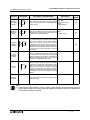
Hardware warnings
1 ) Indicates that the identified danger WILL cause physical and property damage.
2 ) Indicates that the identified danger could POSSIBLY cause physical and property
damage.
3 ) Indicates a point of further interest or further explanation.
Software warning
4 ) Indicates special care must be taken when using this element of software.
5 ) Indicates a special point which the user of the associate software element should
be aware of.
6 ) Indicates a point of interest or further explanation.
v
α2 Simple Application Controllers
vi
α2 Simple Application Controllers
Table of Contents
Guideline of Safety ...............................................................................v
1. Communication Capabilities ..................................................................1-1
1.1 System Configurations ........................................................................................ 1-2
1.1.1
1.1.2
1.1.3
1.1.4
1.1.5
1.1.6
1.1.7
Send an SMS Message to a Mobile Phone............................................................... 1-3
Receive the Short Message from a PC and phone ................................................... 1-3
Detect The Phone Ringing ........................................................................................ 1-4
Send an E-mail Message .......................................................................................... 1-5
Program/monitor from remote PC using a GSM Modem........................................... 1-6
Program/Monitor from remote PC using a standard Modem..................................... 1-6
RS - 232C Straight Cable .......................................................................................... 1-7
1.2 Dedicated Protocol Communication .................................................................... 1-8
1.2.1 Dedicated Protocol Configuration.............................................................................. 1-8
1.2.2 Diagram for RS-232C Cross Cable ........................................................................... 1-8
2. SMS/SMR/CD Functions and the Modem Setting.................................2-1
2.1 Set the parameters of the GSM modem from VLS software. .............................. 2-1
2.1.1 GSM & Serial Communication Dialog Box ................................................................ 2-2
2.1.2 The “Initialize Modem...” Setting................................................................................ 2-3
2.1.3 Pre-Configured GSM Modem Initialization Setting .................................................... 2-3
2.2 The GSM/SMS Function Block ............................................................................ 2-6
2.2.1 The Short Message Service (SMS) ........................................................................... 2-7
2.2.2 SMS Setting Dialog Box ............................................................................................ 2-8
2.3 The SMR Function Block ................................................................................... 2-10
2.3.1 The Short Message Receiving (SMR) ..................................................................... 2-11
2.4 The CD Function Block...................................................................................... 2-14
2.4.1 Call Detect (CD) ...................................................................................................... 2-15
2.5 Set GSM Modem Parameters from the Front Panel Keys................................. 2-17
2.5.1
2.5.2
2.5.3
2.5.4
2.5.5
ComFormat ............................................................................................................. 2-17
The GSM Init Command (GSM Initialization Command)......................................... 2-18
Pin Code.................................................................................................................. 2-18
Set SMS .................................................................................................................. 2-19
GSM Status ............................................................................................................ 2-20
2.6 Characters in GSM Protocol .............................................................................. 2-21
2.6.1 The GSM Character Table ...................................................................................... 2-21
2.6.2 French GSM Characters ......................................................................................... 2-22
2.6.3 Italian GSM Characters ........................................................................................... 2-22
2.7 AL-PCS/WIN-E Program Example .................................................................... 2-23
2.7.1 SMS Function Block Example ................................................................................. 2-23
2.7.2 SMR Function Block Example ................................................................................. 2-26
2.7.3 CD Function Block Example.................................................................................... 2-29
vii
α2 Simple Application Controllers
3. Remote Access .....................................................................................3-1
3.1 GSM Remote Access .......................................................................................... 3-1
3.1.1
3.1.2
3.1.3
3.1.4
3.1.5
3.1.6
3.1.7
3.1.8
Set Parameters from the VLS software ..................................................................... 3-1
GSM & Serial Communication Dialog Box ................................................................ 3-2
GSM Modem Settings ............................................................................................... 3-3
The GSM Init Command (GSM Initialization Command)........................................... 3-3
Command Setting ..................................................................................................... 3-4
Delay Time ................................................................................................................ 3-4
GSM Remote Command ........................................................................................... 3-4
The PIN Code............................................................................................................ 3-4
3.2 Standard Modem Remote Access ....................................................................... 3-5
3.3 Set Parameters from VLS software ..................................................................... 3-5
3.3.1
3.3.2
3.3.3
3.3.4
3.3.5
GSM & Serial Communication Dialog Box ................................................................ 3-6
Standard Modem Settings ......................................................................................... 3-7
The Command Setting .............................................................................................. 3-7
The Delay Time Setting ............................................................................................. 3-7
Standard Preconfigured Modems.............................................................................. 3-8
4. SMS Messaging Diagnostics.................................................................4-1
4.1 Check points for Mobile Phone Communication Problems.................................. 4-1
4.2 Check points for E-mail Communication Problems ............................................. 4-1
4.3 GSM Status ........................................................................................................ 4-2
4.3.1
4.3.2
4.3.3
4.3.4
GSM Status .............................................................................................................. 4-2
CME Error ................................................................................................................. 4-3
CMS Error ................................................................................................................. 4-4
Signal Strength (Sigstreng) ....................................................................................... 4-4
5. Computer Link - Dedicated Protocol .....................................................5-1
5.1 Data Flow by Link ................................................................................................ 5-1
5.2 Configuration Diagram......................................................................................... 5-3
5.2.1 Cross-Cable Diagram ................................................................................................ 5-3
5.3 How to read Dedicated Protocol .......................................................................... 5-4
6. AL-PCS/WIN-E Settings for Dedicated Protocol ...................................6-1
6.1 GSM and Serial Communication Setting ............................................................. 6-1
6.2 Function Blocks ................................................................................................... 6-6
6.3 Settings for Dedicated Protocol - Front Panel Keys .......................................... 6-11
6.3.1
6.3.2
6.3.3
6.3.4
6.3.5
6.3.6
6.3.7
6.3.8
6.3.9
6.3.10
6.3.11
Top Menu Setting/Serial Com Settings ................................................................... 6-11
The “Other Com” Settings ....................................................................................... 6-11
The Comformat (Communication Format)............................................................... 6-11
Data Length ............................................................................................................. 6-11
Parity ....................................................................................................................... 6-11
Stop Bits .................................................................................................................. 6-11
Baud Rate ............................................................................................................... 6-11
Default ..................................................................................................................... 6-12
Station Number ....................................................................................................... 6-12
Link Block ................................................................................................................ 6-12
Function Block Bit and Word Data .......................................................................... 6-12
viii
α2 Simple Application Controllers
7. The Command String ............................................................................7-1
7.1 Format “A” ........................................................................................................... 7-2
7.2 Format “B” Message ............................................................................................ 7-3
7.3 Control Protocol elements ................................................................................... 7-5
7.3.1
7.3.2
7.3.3
7.3.4
7.3.5
7.3.6
7.3.7
7.3.8
7.3.9
7.3.10
7.3.11
Control Codes ........................................................................................................... 7-6
No. of Communication Bytes ..................................................................................... 7-6
Format Number ......................................................................................................... 7-7
Station Number ......................................................................................................... 7-8
Command .................................................................................................................. 7-8
Number of Devices .................................................................................................... 7-9
Device Code ............................................................................................................ 7-11
Device Number........................................................................................................ 7-12
Device Status .......................................................................................................... 7-12
Sum Check .............................................................................................................. 7-13
Error Codes ............................................................................................................. 7-14
7.4 Communication Timing Chart ............................................................................ 7-15
7.4.1 Read/Write Data from the Controller ....................................................................... 7-15
7.4.2 Communication Time .............................................................................................. 7-15
7.5 Character Area Data Transmission ................................................................... 7-16
7.5.1 Read Data Transmission ......................................................................................... 7-16
7.5.2 Write Data Transmission ......................................................................................... 7-17
7.5.3 Time Switch Data Transmission .............................................................................. 7-19
7.6 Commands ........................................................................................................ 7-20
7.6.1
7.6.2
7.6.3
7.6.4
7.6.5
7.6.6
7.6.7
7.6.8
7.6.9
Communication Line Check .................................................................................... 7-21
Read Command ...................................................................................................... 7-22
Write Command ...................................................................................................... 7-24
Remote RUN/STOP Operation ............................................................................... 7-26
Time Switch Settings ............................................................................................... 7-27
VLS Time Switch Settings (Sample) ....................................................................... 7-36
RTC Read Command (Ver. 2.20 or later)................................................................ 7-38
RTC Write Command (Ver. 2.20 or later) ................................................................ 7-39
Display Read Command (Ver.3.00 or later) ............................................................ 7-40
7.7 Sample Visual Basic program ........................................................................... 7-45
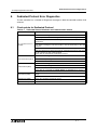
8. Dedicated Protocol Error Diagnostics ...................................................8-1
8.1 Check points for Dedicated Protocol .................................................................. 8-1
ix
α2 Simple Application Controllers
MEMO
x
α2 Simple Application Controllers
1.
Communication Capabilities 1
Communication Capabilities
The α 2 Simple Application Controller has a wide range of communication capabilities that
include remote programming, sending SMS messages to mobile telephones or e-mail
accounts, and reading/writing data using a dedicated protocol. These powerful features bring a
new era of information transfer possibilities to the simple application controllers.
The α 2 can be used to monitor and control machines in remote stations and notify
maintenance personnel in case of machine error or emergency situations. Remote monitoring
through the AL-PCS/WIN-E software (version 2.00 onwards), hereafter referred to as VLS, can
provide machine production and status updates as well as enable programming or parameter
updates without the necessity of local access.
The Dedicated Protocol option gives the user the ability to transfer and monitor data from a
peripheral device without the use of VLS software. Programmers familiar with C, C++, Visual
Basic, or similar packages can write specialized communication programs.
Both standard and GSM modems can connect to the α2 controller.
The most powerful function is the ability to send SMS packets to e-mail accounts or mobile
phones.
The new functional block which strengthens the communication from external equipment was
added to α2 Controller (version 2.20 or later).
The new functional blocks is "Short Message Receiving(SMR) "and" Call Detect (CD)."
"Short Message Receiving (SMR)" changes an output by the character string of a mail
account. And "Call Detect (CD)" By GSM modem or an analog modem that supports"Calling
Line Identification Presentation(CLIP)", an output is changed by call RING of a telephone.
This functionality enables messages to be sent from remote locations to maintenance personnel or the appropriate staff thus reducing downtime for machines and the necessity for on site
personnel at each location. The α2 Series Controller can connect to a GSM modem or standard modem to provide remote program upload/download, to monitor devices, set Function
Block parameters, or change the I/O status. Program upload/download can be performed
remotely by a PC that is using VLS software.
The procedure for Dedicated Protocol, which can remotely monitor or set parameters without
using the VLS software, is discussed in Chapters 5 - 9.
Error messages can be prepared and placed on the α2 display to be sent as the SMS packet.
Please refer to section 2.3 to view the available character set for SMS/GSM communication.
The α 2 Series Controllers communicates with a GSM or Standard modem from the
connection port on the right side.
Note: The α controller communicates to a modem via the left side port and cannot connect to
a GSM modem.
1-1
α2 Simple Application Controllers
1.1
Communication Capabilities 1
System Configurations
There are four methods of modem communication available in the α2 (AL2-14MR-*,
AL2-24MR-*) Series Controllers
1 ) Send an SMS packet to a Mobile phone.
2 ) Send an SMS packet (inside an e-mail) to an e-mail account.
3 ) Remote access via GSM modem.
4 ) Remote access via standard Modem.
5 ) RS-232C Communication for Dedicated Protocol.
The configurations and equipment are listed below.
Using Dedicated Protocol
α2
Series
Remote Maintenance (Using Telephone Line)
Modem
Modem
Remote Maintenance (Using Radio Wave), Sending E-Mail
Modem
GSM
Modem
Sending SMS Message
Personal computer
- Programming Software
(AL-PCS/WIN-E)
- Dedicated protocol
- E-Mail application
Cellular Phone
(Supporting SMS message)
1-2
α2 Simple Application Controllers
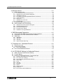
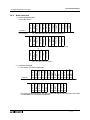
1.1.1
Communication Capabilities 1
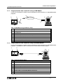
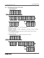
Send an SMS Message to a Mobile Phone
The contents of the display screen will be sent as an SMS packet to a mobile telephone.
➄
➃
➀
➁
+
-
(A) (B)
1
2
3
4
5
6
DC INPUT
7
8
9
10 11
12 13
SMS Provider
14 15
POWER
24V DC
ESC
+
-
OK
➂
AL2-24MR-D
RELAY
OUTPUT
OUT1
OUT2
OUT3
OUT4
5
6
7
8
9
OUT
Table 1.1:SMS Message Setup
No.
1.1.2
Description
1
α2 (AL2-14MR-*, AL2-24MR-*) Series Controller
2
AL2-GSM-CAB
3
GSM Modem (with SIM card and Antenna)
4
SMS Provider
5
Mobile Telephone
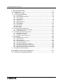
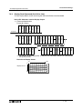
Receive the Short Message from a PC and phone
The GSM short message (SM) can be sent from a Mobile phone, a Normal Phone (with SM
functionality) or PC to a GSM modem that is connected to an α2 controller.
➄
➃
➀
➁
+ -
(A)
(B)
S M S P ro vid er
DC INPUT
1
2
3
4
5
6
7
8
9
10
11
12
13
14
15
POWER
24V DC
E SC
+
OK
AL2-24MR-D
RELA Y
OUTPUT
OU T1
OU T2
OU T3
OU T4
5
6
7
8
9
OU T
➂
Table 1.2:SMS Message Setup
No.
Description
1
α2 (AL2-14MR-*, AL2-24MR-*) Series Controller
2
AL2-GSM-CAB
3
GSM Modem (with SIM card and Antenna)
4
SMS Provider
5
Mobile Telephone, Normal Phone (with SM functionality), PC
1-3
α2 Simple Application Controllers
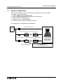
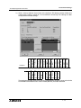
1.1.3
Communication Capabilities 1
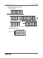
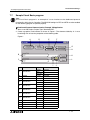
Detect The Phone Ringing
In case a GSM modem or an analog modem that supports Calling Line Identification Presentation (CLIP) is called, the number of the calling partner is sent by the modem by the AT notification "+CLIP" attached to the RING notification.
➀
➁
+
-
(A) (B)
1
2
3
4
5
6
DC INPUT
7
8
9
10
11
12
13
14
15
POWER
24V DC
ESC
➅
+
-
OK
➂
AL2-24MR-D
RELA Y
OUTPUT
OUT1
OUT2
OUT3
OUT4
5
6
7
8
9
OUT
➀
CALL
➁
+
-
(A) (B)
DC INPUT
1
2
3
4
5
6
7
8
9
10
11
12
13
14
15
POWER
24V DC
ESC
+
OK
AL2-24MR-D
RELA Y
OUTPUT
OUT1
OUT2
OUT3
OUT4
5
6
7
8
9
OUT
➃
➄
Table 1.3:SMS Message Setup
No.
Description
1
α2 (AL2-14MR-*, AL2-24MR-*) Series Controller
2
AL2-GSM-CAB
3
GSM Modem (with SIM card and Antenna)
4
RS-232C Straight Cable (See Section 1.1.7)
5
Standard Modem
6
Mobile Telephone, Normal Phone
1-4
α2 Simple Application Controllers
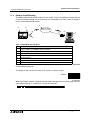
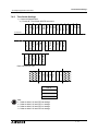
1.1.4
Communication Capabilities 1
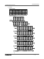
Send an E-mail Message
The SMS packet can be placed inside an e-mail as text. The e-mail address is entered into α2
system parameters through the VLS software or the controller main menu. Refer to chapter 2
to 4 for further detailed information.
➀
➃
➁
+
-
(A) (B)
1
2
3
4
5
6
DC INPUT
7
8
9
10
11
12
13
14
GSM Gateway
Service Provider
➄
15
POWER
24V DC
➅
➆
ESC
+
OK
AL2-24MR-D
RELAY
OUTPUT
OUT1
OUT2
OUT3
OUT4
5
6
7
8
9
OUT
➂
Table 1.4:GSM Modem E-mail Setup
No.
Description
1
α2 (AL2-14MR-*, AL2-24MR-*) Series Controller
2
AL2-GSM-CAB
3
GSM Modem (with SIM card and Antenna)
4
GSM Gateway Provider
5
Standard modem
6
Straight cable
7
PC with VLS software
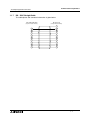
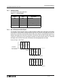
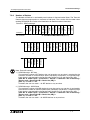
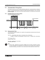
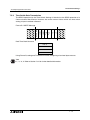
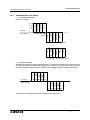
The SMS packet will be the contents of the Display screen as the Input pin for the SMS/GSM
Function Block comes ON.
The display screen consists of 4 rows of 12 columns as shown at right.
4 Rows
12 Columns
When the Display contents are placed into the SMS message or the e-mail message, they columns will be lined up as a continuous string of 48 characters.
1-5
α2 Simple Application Controllers
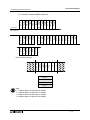
1.1.5
Communication Capabilities 1
Program/monitor from remote PC using a GSM Modem
Use the VLS software to monitor and set parameters and bit devices or to upload/download
programs.
➀
➃
➁
+
-
(A) (B)
1
2
3
4
5
6
DC INPUT
7
8
9
10
11
12
13
14
➅
G S M G a te w a y
S e rvice P ro vid e r
VLS
P ro g ra m
7
15
POWER
24V DC
ESC
➄
+
OK
➂
AL2-24MR-D
RELAY
OUTPUT
OUT2
OUT1
OUT4
OUT3
5
6
7
8
9
OUT
Table 1.5:GSM Modem Program/Monitor Setup
No.
1.1.6
Description
1
α2 (AL2-14MR-*, AL2-24MR-*) Series Controller
2
AL2-GSM-CAB
3
GSM Modem (with SIM card and antenna)
4
GSM Gateway Service Provider
5
Standard Modem
6
RS-232C Cable specified by Modem Manufacturer
7
PC with VLS software
Program/Monitor from remote PC using a standard Modem
Use the VLS software to monitor and set parameters and bit devices or to upload/download
programs. The Modem on the PC end must be a serial communication modem.
c
d
+
-
(A) (B)
1
2
3
4
5
6
DC INPUT
7
8
9
10
11
12
13
14
h
15
POWER
24V DC
VLS
Program
i
ESC
+
-
OK
AL2-24MR-D
RELAY
OUTPUT
OUT1
OUT2
OUT3
OUT4
5
6
7
8
g
9
OUT
e
f
Table 1.6:Standard Modem Setup
No.
Description
1
α2 (AL2-14MR-*, AL2-24MR-*) Series Controller
2
AL2-GSM-CAB
3
RS-232C Straight Cable (See Section 1.1.7)
4
Standard Modem
5
Standard Modem
6
RS-232C Cable as specified by Modem manufacturer
7
PC with VLS software
1-6
α2 Simple Application Controllers
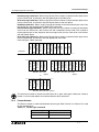
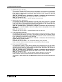
1.1.7
Communication Capabilities 1
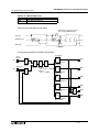
RS - 232C Straight Cable
The cable pinout and connector information is given below.
A L 2 -G S M -C A B S id e
(9 -p in D -S u b fe m a le )
M o d em S id e
(2 5 -p in D -S u b m ale )
1
1
8
2
3
3
2
4
20
5
7
6
6
7
4
8
5
9
22
1-7
α2 Simple Application Controllers
1.2
Communication Capabilities 1
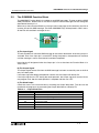
Dedicated Protocol Communication
The α2 (AL2-14MR-*, AL2-24MR-*) Series Controller can transfer data To/From a personal
computer, HMI, or other peripheral equipment via Dedicated Protocol. Programs for Dedicated
Protocol can be written in C++. Visual Basic, or similar high-level programming languages.
Please see the information in Chapters 5 for more information on Dedicated Protocol.
1.2.1
Dedicated Protocol Configuration
The peripheral equipment acts as the Master in the Dedicated Protocol configuration. The
communication takes place via a 1:1 RS-232C communication link.
f
c
+
d
-
(A) (B)
1
2
3
4
5
6
DC INPUT
7
8
9
10
11
12
13
14
e
15
POWER
24V DC
ESC
+
-
OK
AL2-24MR-D
RELAY
OUTPUT
OUT1
OUT2
OUT3
OUT4
5
6
7
8
9
OUT
Table 1.7:Dedicated Protocol Setup
No.
1.2.2
Description
1
α2 (AL2-14MR-*, AL2-24MR-*) Series Controller
2
AL2-GSM-CAB Cable
3
RS-232C Cross Cable (see section 1.2.2)
4
PC or other peripheral device
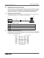
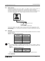
Diagram for RS-232C Cross Cable
The pinouts and connector types for the RS-232C cross cable are shown in the figure below.
Both the connectors and the wiring are equivalent so that either side can be connected to the
AL2-GSM-CAB or the peripheral device.
(9-pin D-Sub female)
(9-pin D-Sub female)
2
2
3
3
4
4
5
5
6
6
7
7
8
8
1-8
α2 Simple Application Controllers
2.
SMS/SMR/CD Functions and the Modem Setting 2
SMS/SMR/CD Functions and the Modem Setting
SMS messages can be sent to mobile phones and e-mail accounts via a GSM modem if
certain parameters in the α2 controller are correctly configured.
The output of SMR changes, when the command text is exactly included in Short Message.
The output of CD changes, when called from the modem that supports Calling Line Identification Presentation (CLIP).
These parameters can be set quickly and easily in the VLS software or from the front panel
keys.
Refer to section 1.1 for the system configuration.
2.1
Set the parameters of the GSM modem from VLS software.
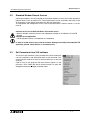
The Visual Logic Software (VLS) provides the easiest method to
set the parameters and download them to the controller. The
communication method is the first setting necessary in the VLS
software.
When use a standard modem by CD Funcion Block, see section
3.3.
Open or start a new program and then choose “Option” on the
menu bar. Click “GSM and Serial Communication” to open the
dialog box necessary to begin parameterisation.
2-1
α2 Simple Application Controllers
2.1.1
SMS/SMR/CD Functions and the Modem Setting 2
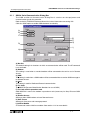
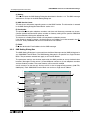
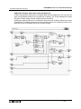
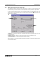
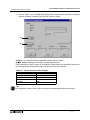
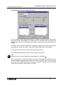
GSM & Serial Communication Dialog Box
The GSM and Serial Communication Dialog Box is used to set the equipment and
communication type for the controller.
Refer to the AL-PCS/WIN-E Software Manual for further information concerning VLS.
Click the “GSM” option to enable GSM telemetric functionality.
A)
B)
C)
D)
H)
E)
F)
G)
I)
A) Not Use
This default setting is for situations in which no communication will be used. The AT command
is not activated.
B) Modem
This setting is used when a standard modem will be connected to the α2 for use in Remote
Access.
C) GSM
This setting is used when a GSM modem will be connected either to send an SMS message or
for Remote Access.
D) Other
This setting is used for Dedicated Protocol communication.
E) Pin Code
The GSM PIN (Personal Identification Numbers for use of GSM)
F) Pin Code with the quotation mark
GSM SIM PIN is sent to the modem in quotation marks (necessary for Sony Ericsson GSM
modem)
G) Remote Access
Setting to allow GSM modems to have Remote Access.
H) Data Format
Settings for Com ports and message protocol.
I) Initialize Modem
AT Command used to initialize a modem. See section 2.1.2 for more details.
2-2
α2 Simple Application Controllers
2.1.2
SMS/SMR/CD Functions and the Modem Setting 2
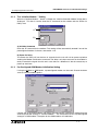
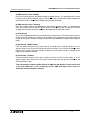
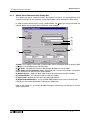
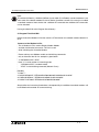
The “Initialize Modem...” Setting
When the “Initialize Modem...” button is clicked, the “Initialize Controller Modem” dialog box is
displayed. This box is used to enter the AT command for the modem and the “Power On
Delay” time.
A)
B)
A) Initialize Command
Enter the AT command for the modem. This setting will be automatically entered if one of the
preconfigured modems is chosen, see section 2.1.3.
B) Power On Delay
The Power On Delay will set the time in seconds that the α2 will wait on power-up before
sending the Modem Initialization command. The delay can help to ensure that the modem is
ready to receive the signal from the α2 in case there is a difference in the time necessary to
power-up each item.
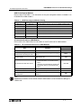
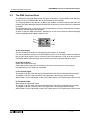
2.1.3
Pre-Configured GSM Modem Initialization Setting
If using the Modem or GSM option, a preconfigured modem can be used. Choose the down
arrow to view the modem options.
Choose one of the listed modems and the AT command will be automatically entered into the
software parameter settings in “Initialize Modem...” The frame above shows a preconfigured
setting for a GSM modem. The option for the GSM modems is listed below.
2-3
α2 Simple Application Controllers
SMS/SMR/CD Functions and the Modem Setting 2
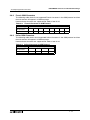
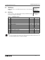
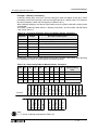
GSM Preconfigured Modems
Please refer to the Table 2.1 for information on the pre-configured modems available in ALPCS/WIN-E for GSM modems.
Table 2.1: GSM Preconfigured Modem Setting
Maker name
Model name
Modem command (AT command)
Mitsubishi
MIM-G01
Siemens
TC35i
AT+IPR=9600;+IFC=0,0;+CMEE=1;E0S0=2&W
Siemens
MC35i
AT+IPR=9600;+CMEE=1;E0S0=2&S0\Q0&W
Siemens
Siemens M20T
AT+IPR=9600;+IFC=0,0;+CMEE=1;E0S0=2&W
Sony Ericsson
GM29
AT+IPR=9600;+IFC=0,0;+CMEE=1;E0S0=2&W
Tixi
HNG1
AT+IPR=9600;+CICB=0;+IFC=0,0;+CMEE=1;E0S0=2&W
Wavecom
WMOD2
AT+IPR=9600;+CICB=0;+IFC=0,0;+CMEE=1;E0S0=2&W
AT+IPR=9600;+IFC=0,0;+CMEE=1;E0S0=2&W
AT Command Profile for GSM Modems
Please refer to the Table below for information on the AT command for GSM modems.
Table 2.2: AT Command Reference for GSM Modems
Item
Content
Example Setting
Siemens M20T
Enable command echo
Echo mode OFF
Set number of rings before
automatically answering the call
Enable automatic answering on the ring
twice
S0=2
Set circuit data set ready (DSR)
function mode
DSR always ON
&S0
•
E0
Specifies the method which will be used
by TE when data is received from TA:
None
Specifies the method which will be used
by TA when data is received from TE:
None
+IFC=0,0
Enable result code and use numeric value
+CMEE=1
Set fixed local rate
Baud Rate: 9600 bps
+IPR=9600
Store current parameter to use
defined profile
The user profile is stored in non-volatile
memory
Set TE-TA local data flow control
Report mobile equipment error
•
&W
Note:
Additional parameters for the Siemens M20T GSM modem can be included via editing the
GSM.ini file.
2-4
α2 Simple Application Controllers
SMS/SMR/CD Functions and the Modem Setting 2
Note:
The Siemens M20T GSM modem has been used as the default modem for the α 2 Series
Controller, however, if the user has installed a GSM modem of their choice with a different AT
command then additional AT commands can be included.
Having installed VLS to the Program files directory.
C:\Program Files\Alvls\BIN
please choose the GSM.ini file that contains AT information for GSM modem selection in VLS.
Contents of the GSM.ini file:
; This is GSM.ini File, used to Display GSM Modem Models
; and their Initialization commands. This file is used
; while Initializing the Controller GSM.
;
; Please add any new Modem models and Initializing commands
; only at the end of the file. An example is given below:
;
;1="USRoboticsXXX","AT&F"
; Here "1" is serial number in increasing order
;
"USRoboticsXXX" is GSM Modem model
;
"AT&F" is the initializing command (Max 64 Chars).
;
[Modem]
1="New",""
2="SIEMENS M20T","ATE0S0=2&S0;+IFC=0,0;+CMEE=1;+IPR=9600&W"
Simply follow the instruction listed above, subsequently, the additional GSM modem will be
included with attached AT command string.
2-5
α2 Simple Application Controllers
2.2
SMS/SMR/CD Functions and the Modem Setting 2
The GSM/SMS Function Block
The GSM/SMS Function block is the trigger to send SMS messages. To enter or edit the GSM/
SMS parameters, double click on the icon to open the Short Message Service dialog box
described in Section 2.2.2.
When two or more Function Blocks are trying to send a message at the same time, the first to
connect will send its SMS message. The other GSM/SMS FB(s) will be placed in “Wait” status.
All the FBs will send their messages in turn.
(B
A)
(C
A) The Input Signal
The α2 controller will send the SMS message to the chosen destination when the input pin is
activated. Even if the Input pin is turned OFF during the process, the operation will continue
until the message is sent or three retries have been completed.
Input signals will be ignored when the Output pin is On or the when the Function Block is in
“Wait” status.
B) The Output Signal
The Output signal comes ON when the SMS message has been successfully sent or the final
retry has taken place.
If the Input signal that began the operation remains ON, the Output will remain ON.
If the Input signal turns OFF during the send operation, the Output signal will remain ON for
one program scan after the send operation is complete and then turn OFF.
C) The Word Output
Check the status of the transmission by checking the Output Word data. The data can be
checked in the program or by connecting the Output Word data to a Display FB.
Table 2.3:
Output Word Value
Bit
Description
b0
Transmission is Complete
b1
Transmission or retry in Progress
b2
Transmission is in “Wait” status
b3
Transmission Failed
b4
Transmission did not occur due to an SMS Parameter Error
b5 - b15
Reserved, will always be 0
2-6
α2 Simple Application Controllers
SMS/SMR/CD Functions and the Modem Setting 2
After the Input Pin is turned OFF, the Word Output will also be reset to 0 when the
communication is complete.
Note:
The Word Value will display a hexadecimal number. Convert the hexadecimal number to
binary form to check the values against Table 2.5 Output Word Value parameters. It is possible
that multiple bits will be ON simultaneously.
The status of the entire controller can be seen in the Diagnosis of Controller dialog box
described in Chapter 4.
Note:
Transmission of UCS2 encoded short messages to an email account is not necessarily supported for a SMS Gateway. In the event no support by the SMS Gateway, UCS2 encoded short
messages cannot be sent to an email account and a fax machine.
Please contact the used GSM network provider.
2.2.1
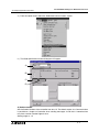
The Short Message Service (SMS)
The Short Message Service dialog box is used to choose whether to send the SMS message
to a mobile phone or an e-mail address. If an e-mail message is chosen, the address is
entered in the E-mail entry block at the bottom of the box. Only one e-mail address can be
entered per GSM/SMS Function Block.
B)
A)
C)
D)
E)
F)
A) Comment
Input a comment to label the function block. The comment will be shown on the VLS software
display if the “Display Comment” block is checked.
B) Display Signal Number
Check this box to display the Function Block number on the VLS software display.
2-7
α2 Simple Application Controllers
SMS/SMR/CD Functions and the Modem Setting 2
C) Setting
This box will open the SMS Setting Dialog box described in Section 2.2.2. The SMS message
destinations are input in the SMS Setting dialog box.
D) SMS Service Center
This box shows information regarding access to the SMS Provider. The information is entered
in the SMS Setting Dialog Box described in section 2.2.2.
E) Destination
The possible Destination telephone numbers and the e-mail Gateway parameter are shown.
Choose the desired Destination phone number or Gateway setting for the specific GSM/SMS
Function Block by clicking the appropriate circle.
The choice of a mobile phone number will complete the selection process.
If the Gateway setting is chosen, the destination e-mail address must be entered in the “Email” box. Every GSM/SMS FB can have a different e-mail address.
F) E-Mail
Enter the destination E-mail address for the SMS message.
2.2.2
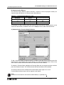
SMS Setting Dialog Box
The SMS Setting Dialog box is accessed from the Short Message service (SMS) dialog box in
any GSM/SMS Function Block. The SMS Setting dialog box is not specific to a single Function
Block. The parameters entered here apply to all Function Blocks.
The parameter settings are the data required by the SMS provider to set up the destination
locations. Messages can be sent to 1) three telephone numbers or 2) two telephone numbers
and one Gateway number. The same Gateway can be used for multiple
e-mail accounts so that the only limit on e-mails is the α2 programming memory (200 FBs,
5000 bytes). Each GSM/SMS Function Block can service a single e-mail address.
(C
A)
B)
D)
E)
2-8
α2 Simple Application Controllers
SMS/SMR/CD Functions and the Modem Setting 2
A) SMS Service Center - Mobile
Enter the number given by the SMS Provider for Mobile access. It is possible that the same
number will be used for Gateway access. Please verify with the Service Provider whether the
International code is needed at the beginning of the phone number.
B) SMS Service Center - Gateway
Enter the number given by the SMS Service Provider for Gateway access. It is possible that
the same number will be used for Mobile access. Please verify with the Service Provider
whether the International code is needed at the beginning of the phone number.
C) Valid Period
This is the requested period for the message to exist on the Server. The time can be set from a
minimum of five minutes to a maximum or 63 weeks. This parameter is ultimately under the
control of the Service Provider and the time period will be decided according to their company
policy.
D) Destination - Mobile Phone
Click the Mobile Phone circle to input data for a mobile phone. Use the “Name #” as an
optional memo area. Enter the Destination phone number in the “Phone Number #” box.
Please verify with the Service Provider whether the International code is needed at the
beginning of the phone number.
E) Destination - Gateway
Click the Gateway circle to input data in order to send an e-mail. Use the “Name #” as an
optional memo area. Enter the e-mail server access code from the Service Provider in the
“Phone Number #” box.
These destination numbers will be valid for all SMS function blocks. E-mails can be sent
to as many addresses as the α 2 memory allows. SMS messages can be sent to a
maximum of three telephone numbers.
2-9
α2 Simple Application Controllers
2.3
SMS/SMR/CD Functions and the Modem Setting 2
The SMR Function Block
The GSM short message (SM) can be sent from a cell phone, a normal phone (with SM functionality) or PC to a GSM modem that is connected to an α2 controller.
α 2 controller detects the delivery of SM by the modem and downloads the SM from the
modem.The Short Message Receive FB (SMR FB) searches for the occurrence of a command
in the SM.
The command is given as text string in the FB parameter.In case the command text is exactly
included in the SM, outputs are changed.
To enter or edit the SMR parameters, double click on the icon to open the Short Message
Receiving dialog box described in Section 2.3.1.
A)
(C
B)
(D
A) The Input Signal
The α2 controller will receive a message when the input pin is activated.
For normal operation the input must be ON.When Input is OFF, all output values are hold and
the function block doesn't care an incoming short message.Input is ON when left open(not
connected).When Reset and Input are ON at the same time, only Reset becomes active.
B) The Reset Signal
Resets the outputs when ON.
Reset takes priority over Input and takes priority over a command in an incoming short
message.Reset is OFF when not connected.
C) The Output Signal
The output is set ON, when the switch ON command is found in the received short message.
The output is set OFF, when the switch OFF command is found in the short message.
When Reset is ON, the bit output is reset (OFF).When Input is OFF the bit output value is hold.
D) The Word Output
Word output for transferred values.
The output is set ON, when the switch ON command is found in the received short message.
The output is set OFF, when the switch OFF command is found in the short message.
When Reset is ON, the bit output is reset (OFF).When Input is OFF the bit output value is hold.
2 - 10
α2 Simple Application Controllers
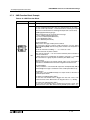
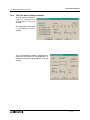
2.3.1
SMS/SMR/CD Functions and the Modem Setting 2
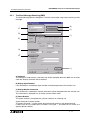
The Short Message Receiving (SMR)
The Short Message Service dialog box is used for a parameter setup when receiving a short
message.
A)
B)
C)
D)
F)
E)
G)
H)
I)
A) Comment
This edit box is used to enter a comment that will be displayed above the SMR icon and only
when the "Display Comment" box is checked.
B) Display Signal Number
If this check box is checked the signal number will be displayed next to the function icon.
C) Display Monitor Information
If this check box is checked the monitor information will be displayed below the function icon.
This information is displayed only in monitor and simulation mode.
D) Phone Number
This phone number is compared with a phone number of an incoming call.
Asterix Character in phone number
The asterix character '*' can be used to terminate phone number or can be stand-alone.
It takes place for any combination of numbers. Using the '*', one SMR FB can switch for a
group of phone numbers.
2 - 11
α2 Simple Application Controllers
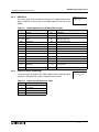
SMS/SMR/CD Functions and the Modem Setting 2
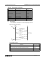
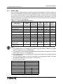
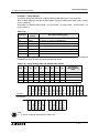
Table 2.4: Phone numbers and Outputs
FB number
Caller's phone number
FB Output
+49 21 02 12 34 56 7
+49 21 02 12 34 56 7
changed
+49 21 02 12 34 56 7
+49 21 02 12 34 56 8
no change
+49 21 02 12 34 56 7
+49 21 02 12 34
no change
+49 21 02 12 34 56 7
+49 21 02 12 34 56 78
no change
+49 21 02 12 34 56 7*
+49 21 02 12 34 56 7
no change
+49 21 02 12 34 56
+49 21 02 12 34 56 7
no change
+49 21 02 12 34 56 *
+49 21 02 12 34 56 7
changed
+49 21 02 12 3*
+49 21 02 12 34 56 7
changed
+49 21 02 12 3*
+49 21 02 12 34 56 8
changed
+49 21 02 12 3*
+49 21 02 12 34 56 78
changed
*
Any phone number
changed
+*
Any international phone number
changed
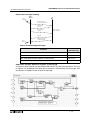
E)
- Acknowledge
If this check box is checked, then an Acknowledge flag will be set.
Report short message handling
Short
Message
GSM
Modem
α2
New Short Message
received,stored in memory
Request Short
Message
Transfer Short
Message
Check Password
Check Commands
Erase SM
Transfer report SM.
See Message Table
Short
Message
Acknowledge messages
Condition
α2
α2
α2
α2
Transmitted
Short Message
in Run Mode, all commands of SM successfully processed
"OK"
in Run Mode, some commands in SM were erroneous.
"Error"
in Run Mode, Sender of SM has no authorization
"No access"
in Run Mode, Password Protection Set, Password invalid or not Set
"No access"
2 - 12
α2 Simple Application Controllers
SMS/SMR/CD Functions and the Modem Setting 2
- Retentive
Check the "Retentive" checkbox is store the output value even after a Power cut.
- Maintenance
If this check box is checked the maintenance mode will be initiated.
F) Short Message Age
This value defines the duration of time that the short message is stored.
User can click "+" or "-" button to increase or decrease the short message age.
G) Word Output Range
This parameter is only used for when the word output mode is active.
-Min. value
Lower limit of the word output value. In case the word output value is smaller than
the min. value set, thus, the min. value will become active.
Min. Value range: -32768 (max. value -1)
-Max. Value
Upper limit of word output value. In case the word output value is greater than the max.
value, thus, the max. value will become active.
Max. Value range: 32767 (min. value +1)
H) Short Message Command
-Bit Output
The Bit output can be switched ON and OFF by the appropriate short message
command.
-Word Output
The word output value can be set by the appropriate value held in the short message
command.
I) SMR Password
Setting the SMR password in this dialog box will create a common password for all
equivalent SMR Function blocks.
Setting Range: 0 and 9999.
In order to avoid serious injury and the machine damage caused by unintended SMR FB
operation, provide safety devices as countermeasure.
2 - 13
α2 Simple Application Controllers
2.4
SMS/SMR/CD Functions and the Modem Setting 2
The CD Function Block
In case a GSM modem or an analog modem that supports Calling Line Identification
Presentation (CLIP) is called, the number of the calling partner is sent by the modem by the AT
notification "+CLIP" attached to the RING notification. α2 extracts the callers's number after a
given number of RING notifications.
In case the numbers of digits of both phone numbers and the phone numbers itself are equal,
the CD FB output is switched on.
To enter or edit the SMR parameters, double click on the icon to open the Short Message
Receiving dialog box described in Section 2.4.1.
A)
B)
(C
A) The Input Signal
Enables the CD FB operation.For normal operation the Input must be ON.
When Input is OFF, the output is hold and the function block doesn't check caller's number.
Input is ON when left open (not connected).When Reset and Input are ON at the same time,
only Reset becomes active.
B) The Reset Signal
Resets the bit output when ON
Reset takes priority over Input and takes priority over an incoming call.Thus, when Reset is
ON, an incoming call has no affect.
Reset is OFF when not connected.
C) The Output Signal
Bit output.
The output is set ON, when the caller's number is equal to the stored phone number and Input
is ON.The output state is hold, when Input is OFF, and it is reset (set OFF), when Reset is ON.
2 - 14
α2 Simple Application Controllers
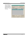
2.4.1
SMS/SMR/CD Functions and the Modem Setting 2
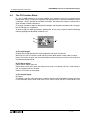
Call Detect (CD)
The Call Detect dialog box is used for a Phone Number and Number of rings setup..
A)
B)
C)
D)
E)
F)
G)
A) Comment
This edit box is used to enter a comment that will be displayed above the CD icon and only
when the "Display Comment" box is checked.
B) Display Signal Number
If this check box is checked the signal number will be displayed next to the function icon.
C) Display Monitor Information
If this check box is checked the monitor information will be displayed below the function icon.
This information is displayed only in monitor and simulation mode.
D) Phone Number
Length: 28 characters, including " +,-,(,),*,0,1,2,3,4,5,6,7,8,9 "
Asterix Character in phone number
The asterix character '*' can be used to terminate phone number or can be stand-alone.
It takes place for any combination of numbers. Using the '*', one CD FB can switch for a group
of phone numbers.
2 - 15
α2 Simple Application Controllers
SMS/SMR/CD Functions and the Modem Setting 2
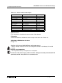
Table 2.5: Phone numbers and Outputs
FB number
+49 21 02 12 34 56 7
Caller's phone number
+49 21 02 12 34 56 7
FB Output
changed
+49 21 02 12 34 56 7
+49 21 02 12 34 56 8
no change
+49 21 02 12 34 56 7
+49 21 02 12 34
no change
+49 21 02 12 34 56 7
+49 21 02 12 34 56 78
no change
+49 21 02 12 34 56 7*
+49 21 02 12 34 56 7
no change
+49 21 02 12 34 56
+49 21 02 12 34 56 7
no change
+49 21 02 12 34 56 *
+49 21 02 12 34 56 7
changed
+49 21 02 12 3*
+49 21 02 12 34 56 7
changed
+49 21 02 12 3*
+49 21 02 12 34 56 8
changed
+49 21 02 12 3*
+49 21 02 12 34 56 78
changed
*
Any phone number
changed
+*
Any international phone number
changed
E) Maintenance
If this check box is checked maintenance mode will be selected.
F) Retentive
Check the "Retentive" checkbox is store the output value even after a Power cut.
G) Number of RING before call detect
Range: 1-20
Cautions for the use of both Call Detec and remote access
- When it remotely accesses from the same telephone number for Call Detect, CD and FB
operate.
Cautions for misoperations
- CD FB operates also by a misoperation of a telephone.
In order to avoid serious injury and the machine damage caused by unintended CD FB
operation, provide safety devices as countermeasure.
2 - 16
α2 Simple Application Controllers
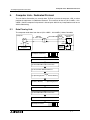
2.5
SMS/SMR/CD Functions and the Modem Setting 2
Set GSM Modem Parameters from the Front Panel Keys
The settings required to send SMS packets via a GSM modem or to set
up the α2 controller for remote access can be accomplished with the
front panel keys.
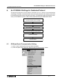
To begin the process from the Top Menu, scroll down to “Others/Serial
Com/GSM” and press “OK” to view the options shown at right.
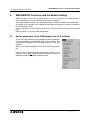
2.5.1
S e r i a l C om
No t Us e
Mo d em
GSM
O t h e r C om
GSM
C o mF o r ma t
GSM I n i t
GSM R e mo t e
P I N Co d e
S e t SMS
GSM S t a t u s
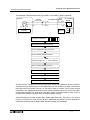
ComFormat
Upon entering the GSM option, the ComFormat dialog will be the first
option. The ComFormat allows the user to set the communication
settings for Data Length, Parity, Stop Bit, and Baudrate. Most
communications can be accomplished with the Default settings.
Scroll to the setting to be adjusted.
Data Length
Select a Data length parameter of 7 or 8 bits.
Parity
Select from three options for Parity - None, Odd or Even.
Stop Bits
Choose the number of stop bits - 1 bit or 2 bits.
Baud Rate
Select the baud rate - 9600 or 19200 bps.
C o mF o r ma t
Da t a L e n g t h
Pa r i t y
S t op b i t
Ba u d r a t e
De f a u l t
Da t a L e n g t h
8 bi t s
7 bi t s
Pa r i t y
No n e
Od d
Ev en
S t op b i t
1b i t
2b i t s
Ba u d r a t e
9600 bps
19200 bps
Default
The controller can be returned to the default communication settings (DataLength = 8 bits;
Parity = None; Stop Bits = 1; and Baud Rate = 9600 bps) by pressing “OK” when the pointer is
on the Default option shown in the ComFormat box.
2 - 17
α2 Simple Application Controllers
2.5.2
SMS/SMR/CD Functions and the Modem Setting 2
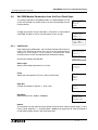
The GSM Init Command (GSM Initialization Command)
The GSM modem must have an initialization command string. After
choosing the “GSM Init” option, the Command and Delay Time settings
will appear.
Command Setting
Choose “Command” to enter the AT command. Details for the AT
command should be included in the literature of the modem.
GSM I n i t
C o mma n d
D e l a y T i me
GSM I n i t 0 1
C o mma n d
[A
]
< = > ? @A BCDE
Enter the string by choosing the characters using the “ ” and “ ”
arrows. When a desired letter is shown onscreen, move to the right by pressing the “ ” key.
The character shown will remain and the cursor will move to the right. Do not press the “OK”
key until the command has been entered in its entirety.
Move to the left for editing purposes with the “ ” key.
Delay Time
The Delay Time Setting will delay the transmission of the initialization
command while the modem completes its power up.
Use the “+” key to increment the value and the “-” to decrement the
value within the range of 0 - 10 seconds. Enter the value by pressing
the “OK” key.
2.5.3
GSM I n i t
D e l a y T i me
0s
Pin Code
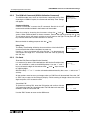
Enter the PIN (Personal Identification Number)
P I N Co d e
It is necessary to enter a PIN received from the Service Provider when
Se t u p
∗∗∗∗
the α2 controller is used to send SMS packets. Use the “+” and “-”
keys to choose the digits of the code and the “ ” and “ ” keys to move
to adjoining digits.
SIM PIN setup “****” or **** can be activated and deactivated by the cursor U and cursor V
soft key.
All the numbers must be set to an integer value or a PIN Error will be received. Press the “OK”
or “ESC” key to return to the PIN entry display. Finish entering all integer values into all four
digits and press “OK” to enter the PIN.
Cancel the PIN
To Cancel an existing PIN, enter the PIN option and confirm with the
“OK” button the intent to Cancel the code. The PIN does not have to be
entered in order to Cancel the PIN.
P IN Code
Can ce l
OK
o r
Use the “ESC” button to return to the GSM menu.
2 - 18
ESC
α2 Simple Application Controllers
2.5.4
SMS/SMR/CD Functions and the Modem Setting 2
Set SMS
The SMS menu is used to set the telephone numbers for the Service
Provider, the destination numbers for mobile phones, the access code
for e-mail messages, and the Validity Period of the messages.
S e t SMS
SMS C 1
SMS C 2
DA 1
DA 2
DA 3
VP
SMS Provider Mobile Access Number (SMSC1)
S e t SMS
01
The SMSC1 is the number used to access the Service Provider section
SMS C 1
for mobile phones. Choose the digits and symbols using the “ ” and
[
]
“ ” arrows. After the digit is set, move to the left or right with the “ ” 9 + - ( ) 0 1 2 3
and “ ” keys. Do not press the “OK” button until the command has
been entered in its entirety.
SMS Provider Gateway Access Number (SMSC2)
S e t SMS
01
The SMSC2 is the number used to access the E-mail gateway
SMSC 2
telephone number of the SMS Service Provider. Choose the digits and
[
]
symbols using the “ ” and “ ” arrows. After the digit is set, move to the
9+ - ( ) 0123
left or right with the “ ” and “ ” keys. Do not press the “OK” button
until the command has been entered in its entirety. This number might be the same as used in
SMSC1.
Destination Address (DA1, DA2, DA3)
S e t SMS
01
Enter the mobile telephone number or the Service Provider e-mail
DA 1
Gateway code in this window. The number entered here can be
[
]
accessed by a GSM/SMS Function Block in the user program when
9+ - ( ) 0123
trying to send an SMS message.
Choose the digits and symbols using the “ ” and “ ” arrows. After the digit is set, move to the
left or right with the “ ” and “ ” keys. Do not press the “OK” button until the command has
been entered in its entirety.
Three destination mobile telephone numbers can be entered, one in each DA address.
Alternately, two mobile phone numbers and one e-mail gateway access code can be entered.
Only one e-mail Gateway access code needs to be entered and then the individual e-mail
addresses can be entered separately in each GSM/SMS Function Block.
Validity Period
The Validity Period is a request to the SMS Service Provider to keep
the message on their Server for a length of time. Each Service
Provider may have their own policies with regard to this time period.
Please check the details with your local Service Provider.
S e t SMS
VP
24 . 0h r s
Use the “+” and “-” keys to change the value within the range of 5 minutes to 63 weeks.
2 - 19
α2 Simple Application Controllers
2.5.5
SMS/SMR/CD Functions and the Modem Setting 2
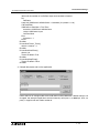
GSM Status
Check the status of the GSM communication in the following
categories.
GSM S t a t u s
St a t us
CME E r r o r
CMS E r r o r
S i gS t r e n g
Status
The status is given in hexadecimal numbers, conver t to binar y
numbers to check against the Status Table shown in Section **. Error
codes are provided in Chapter 4.
GSM S t a t u s
St a t us
0 0 0 0H
CME Error
This CME Error status gives information to the functioning of Mobile
Equipment (ME), please refer to the GSM modem manual for more
details. Reference error Tables are located in Chapter 4 of this manual.
GSM S t a t u s
CME E r r o r
-1
CMS Error
This value gives error information relevant to the Mobile Equipment
(ME) or Network, please refer to the GSM modem manual for more
details. Reference error Tables are located in Chapter 4 of this
manual.
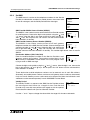
Signal Strength (Sigstreng)
Check the signal strength of the GSM modem signal.
Table 2.6: Signal Strength Reference Table
Value%
GSM S t a t u s
CMS E r r o r
-1
GSM S t a t u s
S i gS t r e n g
0%
Receiving Level
0
-113 dBm or less
3
-111 dBm
6-96
-109 to -53 dBm
100
-51 dBm or greater
2 - 20
α2 Simple Application Controllers
2.6
SMS/SMR/CD Functions and the Modem Setting 2
Characters in GSM Protocol
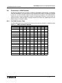
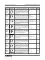
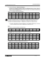
The following table gives the characters available for GSM/SMS communication as defined by
GSM standard 03.38. The code numbers are for reference only and do not need to be entered
by the User. The α2 controller supports more characters than appear in the GSM protocol.
Tables are given for each language to show the unsupported characters and how they will
appear if used in a GSM message. Languages where all characters are supported do not have
GSM character transposition tables.
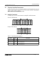
2.6.1
The GSM Character Table
The Table below gives the characters that can be sent by the α2 controller in a GSM message.
Table 2.7:
GSM 03.38 Default Alphabet
Number (Hex)
0
1
2
3
4
5
6
7
0
@
∆
SP
0
¡
P
¿
p
1
£
_
!
1
A
Q
a
q
2
$
“
2
B
R
b
r
3
¥
#
3
C
S
c
s
4
¤
4
D
T
d
t
%
5
E
U
e
u
&
6
F
V
f
v
‘
7
G
W
g
w
(
8
H
X
h
x
9
è
é
ù
ì
ò
Ç
Φ
Γ
Λ
Ω
Π
Ψ
Σ
Θ
)
9
I
Y
i
y
A
LF
Ξ
*
:
J
Z
j
z
B
1)
+
;
K
,
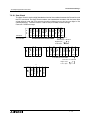
<
L
D
CR
-
=
M
E
Å
å
Æ
æ
ß
É
.
>
N
/
?
O
Ä
Ö
Ñ
Ü
§
k
C
Ø
ø
ä
ö
ñ
ü
à
5
6
7
8
F
l
m
n
o
2 - 21
α2 Simple Application Controllers
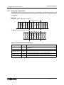
2.6.2
SMS/SMR/CD Functions and the Modem Setting 2
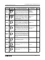
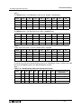
French GSM Characters
The following table shows the unsupported French characters in the GSM protocol and how
those characters will appear in a GSM message.
However these characters are supported Ver. 3.00 or later of α2.
Table 2.8:
French Characters in GSM Protocol
Display Character
Character Type
2.6.3
α2 Character
â
ê
î
ô
û
ë
ï
ç
GSM Character
a
e
i
o
u
e
i
c
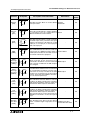
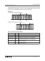
Italian GSM Characters
The following table shows the unsupported Italian characters in the GSM protocol and how
those characters will appear in a GSM message.
However these characters are supported Ver. 3.00 or later of α2.
Table 2.9: Italian Characters in GSM Protocol
Display Character
Character Type
α2 Character
á
í
ó
ú
GSM Character
à
ì
ò
ù
2 - 22
α2 Simple Application Controllers
SMS/SMR/CD Functions and the Modem Setting 2
2.7
AL-PCS/WIN-E Program Example
2.7.1
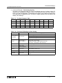
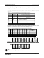
SMS Function Block Example
Table 2.10: GSM Function Block
Set
Item
Function
Description
I
Bit input pin for GSM/SMS function block operation
1) Detects the high status of an input and subsequently sends the
SMS message to the predefined user destination.
2) The SMS message will continue to send regardless of the input
switching to a low state.
3) The incoming high input will be ignored:
a) During a SMS message transmission
b) During the waiting period.
W
I
4) Communication failure (e.g. busy line) will tell the SMS function
block to retry on two further occasions in a period of two minutes.
FB
5)On the third retry the output status will switch to ON and an error
message generated through the word pin of the function block.
O
6) The user may experience incorrect validity period timings. Please
check with your Service Provider.
7) If both the Mobile (SMSC1) and Gateway (SMSC2) numbers are
entered the α2 controller will automatically choose the correct path
number for the SMS in conjunction with the destination chosen. The
destination being either to a mobile phone or an email address.
1) The output status will set ON:
a) In succeeding in sending a SMS message
b) In failing to send a SMS message after three retries.
Output
2) If more than one SMS function block exists on the program, a FIFO
(First In First Out) sequence is performed. *1
3) The following items are available for other function blocks:
a) SMS message sent/SMS failed to be sent after 3 attempts
b) Current Status
Note:
*1 If a number of SMS Function Blocks have been used in one program the user must take
care when calculating the message sending order. The first message to be sent depends
on the first input signal turning ON. Thus, if other messages are waiting to be sent they are
then placed in a waiting queue. However, since the waiting queue is scan dependant, if
after one scan the controller has failed to send the first message due to a busy line, thus,
the following message order is no longer dependant on input signals turning ON but is
solely dependant on the Function Block order.
Table 2.11: Abbreviated terms
Term
Description
I
SMS Function Block Input pin
O
SMS Function Block Output pin
W
SMS Function Block Word Output pin
2 - 23
α2 Simple Application Controllers
SMS/SMR/CD Functions and the Modem Setting 2
Table 2.11: Abbreviated terms
FB
Function Block
SMS
Short Message Service
Timing chart for the SMS function block
Transmission request is ignored
while sending SMS Message.
Input pin
SMS
Message
SMS Message
SMS
Message
*
*
*
Output pin
1 scan time
VLS program example for the SMS function block
Completed
Send
Request
I01
PL
From Off
to On
Stop Retry
I02
1
2
OR
3
O01
CP
S
R SR
FL
SMS
Reset • Output: Continous
priority • On time:
120.1s (1201 × 100ms)
• Off time:
0.1s (1 × 100ms)
Current status=1
(Bit 0=ON)
O02
CP
Current status=2
(Bit 1=ON)
O03
ZC
4≤Current status≤7
(Bit 2=ON)
O04
ZC
8≤Current status≤15
(Bit 3=ON)
1
2
OR
3
O05
O06
CP
Current status≥16
(Bit 4 = ON)
2 - 24
α2 Simple Application Controllers
SMS/SMR/CD Functions and the Modem Setting 2
2 - 25
α2 Simple Application Controllers
2.7.2
SMS/SMR/CD Functions and the Modem Setting 2
SMR Function Block Example
Table 2.12: SMR Function Block
Function
Set Item
E
Description
Bit input pin for the function block operation
1) Cmnd String(Cmmand String)
In case of Word output mode, only one command text can be setup.
In case of Bit output mode, a command text for switching bit output
ON and a command text for switching bit output OFF can be setup.
2)SM Age(Short Massage age)
Setup maximum age of received short message.
a) 5 to 720minutes(Unit:5minutes)
b) 12.5 to 24Hours(Unit:30minutes)
c) 2 to 30day(Unit:1day)
d) 5 to 63week(Unit:1week)
E
O
R
W
3) Phone Number
Setup short message senders phone number.
By setting the phone number in FB parameter, only the Shor t
Message Entity(SME) with the setup phone number can manipulate a
SMR FB.
Up to 28 characters,including “+ , - * 0 1 2 3 4 5 6 7 8 9 “.
FB
Asterix Character in phone number
The asterix character '*' can be used to terminate phone number or
can be stand-alone.
It takes place for any combination of numbers. Using the '*', one SMR
FB can switch for a group of phone numbers.(See Table 2.14)
4) Password
Setup authentication password (4 digit code). The password is
common for all SMR FB and stored in Programm Parameter area.
5) Acknowledge
If this parameter is set and the FB output was manipulated by SM, a
acknowledge message is send back to the sender.(See Table 2.15)
6) Retention
If this flag is set, the SMR FB keeps it's output states at the time of
controller power down.
7) Upper Limit (Word output mode)
In case the transmitted value is bigger than the max. value, max.
value becomes active. Max. Value can be [(min.value + 1)...32767].
8) Lower Limit (Word output mode)
In case the transmitted value is smaller than the min. value, min.
value becomes active. Min. Value can be [-32768...(max. value - 1)]
2 - 26
α2 Simple Application Controllers
Function
SMS/SMR/CD Functions and the Modem Setting 2
Set Item
R
Description
Reset pin for the function block
The SMR FB can be operated in one of two different modes.
Output
1) Bit output.
a) The output is set ON, when the switch ON command is found
in the received short message.
b) The output is set OFF, when the switch OFF command is found
in the short message.
c) When R ON, the bit output is reset (OFF). R takes priority over E.
When E is OFF the bit output value is hold.
2) Word output.
a) Word output for transferred values. The output is set to the
transmitted value, when the set word output command is found
and the value after “=” is valid.
b) When R is ON, the word output is set to zero.
When E is OFF, the word output is hold. R takes priority over E.
Table 2.13: Abbreviated terms
Term
Description
E
SMR Function Block Input pin
R
SMR Function Block Reset pin
O
SMR Function Block Output pin
W
SMR Function Block Word Output pin
FB
Function Block
SMS
Short Message Service
Table 2.14: Phone numbers and Outputs
FB number
Caller's phone number
FB Output
+49 21 02 12 34 56 7
+49 21 02 12 34 56 7
+49 21 02 12 34 56 7
+49 21 02 12 34 56 8
changed
no change
+49 21 02 12 34 56 7
+49 21 02 12 34
no change
+49 21 02 12 34 56 7
+49 21 02 12 34 56 78
no change
+49 21 02 12 34 56 7*
+49 21 02 12 34 56 7
no change
+49 21 02 12 34 56
+49 21 02 12 34 56 7
no change
+49 21 02 12 34 56 *
+49 21 02 12 34 56 7
changed
+49 21 02 12 3*
+49 21 02 12 34 56 7
changed
+49 21 02 12 3*
+49 21 02 12 34 56 8
changed
+49 21 02 12 3*
+49 21 02 12 34 56 78
changed
*
Any phone number
changed
+*
Any international phone number
changed
2 - 27
α2 Simple Application Controllers
SMS/SMR/CD Functions and the Modem Setting 2
Report short message handling
Short
Message
GSM
Modem
α2
New Short Message
received,stored in memory
Request Short
Message
Transfer Short
Message
Check Password
Check Commands
Erase SM
Transfer report SM.
See Message Table
Short
Message
Table 2.15:Acknowledge messages
Condition
α2
α2
α2
α2
Transmitted
Short Message
in Run Mode, all commands of SM successfully processed
"OK"
in Run Mode, some commands in SM were erroneous.
"Error"
in Run Mode, Sender of SM has no authorization
"No access"
in Run Mode, Password Protection Set, Password invalid or not Set
"No access"
Application Example: Switch an irrigation system by SM
A system for plant irrigation can be switched ON and OFF by short message (B10). The start
of irrigation can be delayed. The delay time (in minutes) is transferred by short message. Also
the duration of irrigation can be set by short message.
2 - 28
α2 Simple Application Controllers
2.7.3
SMS/SMR/CD Functions and the Modem Setting 2
CD Function Block Example
Table 2.16: CD Function Block
Function
Set Item
E
Description
Bit input pin for the function block operation
1) Retention
If this flag is set, the CD FB keeps it's output state at the time of
controller power down.
2) Phone Number
Setup short message senders phone number.
By setting the phone number in FB parameter, only the SME with the
setup phone number can manipulate a SMR FB.
Up to 28 characters,including “+ , - * 0 1 2 3 4 5 6 7 8 9 “.
E
O
R
FB
Asterix Character in phone number
The asterix character '*' can be used to terminate phone number or
can be stand-alone.
It takes place for any combination of numbers. Using the '*', one CD
FB can switch for a group of phone numbers.(See Table 2.18)
3) Number of RING
Setup number of RING before call detection(Program Parameter,
common for all CD FBs)
Range:1 to 20
R
Reset pin for the function block
Output
The output is set ON, when the caller's number is equal to the stored
phone number and E is ON.
The output state is hold, when E is OFF, and it is reset (set OFF),
when R input is ON.
Table 2.17: Abbreviated terms
Term
Description
E
CD Function Block Input pin
R
CD Function Block Reset pin
O
SMR Function Block Output pin
FB
Function Block
Table 2.18: Phone numbers and Outputs
FB number
Caller's phone number
FB Output
+49 21 02 12 34 56 7
+49 21 02 12 34 56 7
+49 21 02 12 34 56 7
+49 21 02 12 34 56 8
changed
no change
+49 21 02 12 34 56 7
+49 21 02 12 34
no change
+49 21 02 12 34 56 7
+49 21 02 12 34 56 78
no change
+49 21 02 12 34 56 7*
+49 21 02 12 34 56 7
no change
+49 21 02 12 34 56
+49 21 02 12 34 56 7
no change
+49 21 02 12 34 56 *
+49 21 02 12 34 56 7
changed
+49 21 02 12 3*
+49 21 02 12 34 56 7
changed
+49 21 02 12 3*
+49 21 02 12 34 56 8
changed
+49 21 02 12 3*
+49 21 02 12 34 56 78
changed
*
Any phone number
changed
+*
Any international phone number
changed
2 - 29
α2 Simple Application Controllers
SMS/SMR/CD Functions and the Modem Setting 2
Application Example: Open roller shutter by phone call
A roller shutter gates the entrance to a company field. Normally pedestrians only can pass this
gate. Four employees need to pass the gate with a company car. These employees can open
the gate by simply calling a phone number with their cell-phone.
Opening the gate by phone call is enabled only during normal workdays and business times
(Time Switch). Outside the business times the company owner can enable the function for a
fixed time to give an employee the chance to open the gate.
2 - 30
α2 Simple Application Controllers
3.
Remote Access 3
Remote Access
The settings required to send SMS packets via a GSM modem or to set up the α2 controller for
remote access can be accomplished with the front panel keys. It is possible to perform remote
operations with a standard modem but it is not possible to send SMS packets.
Certain parameters in the α2 controller and GSM modem must be set in order to perform
Remote Access from an external PC. These parameters can be set quickly and easily in the
VLS software or with slightly more effort from the front panel keys.
The equipment and configuration for this style of communication is listed in section 1.1 of this
manual.
3.1
GSM Remote Access
3.1.1
Set Parameters from the VLS software
The Visual Logic Software (VLS) provides the easiest method to
set the parameters and download them to the controller. The
communication method is the first setting necessary in the VLS
software.
Open or start a new program and then choose “Option” on the
menu bar. Click “GSM and Serial Communication” to open the
dialog box necessary to begin parameter input.
3-1
α2 Simple Application Controllers
3.1.2
Remote Access 3
GSM & Serial Communication Dialog Box
The “GSM and Serial Communication” dialog box is used to set the equipment and
communication type for the controller. A short explanation of each parameter is given below.
In order to obtain remote access using a GSM modem, the GSM circle must be clicked, the
Remote Access box checked, and the GSM Pin Code entered.
A)
G)
B)
C)
D)
E)
F)
A) GSM - This setting is used when a GSM modem will be connected either to send an SMS
message or for Remote Access communication.
B) Pin Code - The GSM PIN (Personal Identification Numbers for use of GSM)
C) Pin Code with the quotation mark - GSM SIM PIN is send to the modem in quotation
marks (necessary for Sony Ericsson GSM modem)
D) Remote Access - Setting to allow GSM modems to have Remote Access capability.
E) Initialize Modem - AT Command used to initialize a modem.
F) Data Format - Settings for Com ports and message protocol.
G) Registered GSM Modems - List of available GSM modems for the user to choose from,
however, this list can be extended by writing to the GSM.ini file.
Refer to the section 2.1 for further detailed information concerning VLS settings for remote
access using GSM.
3-2
α2 Simple Application Controllers
3.1.3
GSM Modem Settings
The numerous parameters and options for using the GSM modem can
be set using the front panel keys although this procedure is
significantly more difficult than using the AL-PCS/WIN-E software.
To begin the process from the Top Menu, scroll down to “Others/Serial
Com/GSM” and view the options shown at right.
Comformat (Communication Format)
Upon entering the GSM option, the ComFormat dialog will be the first
option. The Comformat allows the user to set the communication
settings for Data Length, Parity, Stop Bit, and Baudrate.
Scroll to the setting to be adjusted.
Data Length
Select a Data length send parameter of 7 or 8 bits.
Parity
Select from three options for Parity - None, Odd or Even.
Stop Bits
Choose the number of stop bits - 1 bit or 2 bits.
Baud Rate
Select the baud rate - 9600 or 19200 bps.
Remote Access 3
S e r i a l C om
No t Us e
Mo d em
GSM
O t h e r C om
GSM
C o mF o r ma t
GSM I n i t
GSM R e mo t e
P I N Co d e
S e t SMS
GSM S t a t u s
C o mF o r ma t
Da t a L e n g t h
Pa r i t y
S t op b i t
Ba u d r a t e
De f a u l t
Da t a L e n g t h
8 bi t s
7 bi t s
Pa r i t y
No n e
Od d
Ev en
S t op b i t
1b i t
2b i t s
Ba u d r a t e
9600 bps
19200 bps
Default
The controller can be returned to the default communication settings DataLength = 8 bits; Parity = None; Stop Bits = 1; and Baud Rate = 9600 bps - by pressing
“OK” when the pointer is on the Default option.
3.1.4
The GSM Init Command (GSM Initialization Command)
The GSM modem must have an initialization command string. After
choosing the “GSM Init” option, the Command and Delay Time settings
will appear.
GSM I n i t
C o mma n d
D e l a y T i me
3-3
α2 Simple Application Controllers
3.1.5
Command Setting
Choose “Command” to enter the AT command. Details for the AT
command should be included in the literature of the modem.
Remote Access 3
GSM I n i t 0 1
C o mma n d
[A
]
< = > ? @A BCDE
Enter the string by choosing the characters with the “ ” and “ ”
arrows. When a desired letter is shown onscreen, move to the right by pressing the “ ” key.
The character will remain in the previous cursor space. Do not press the “OK” key until the
command has been entered in its entirety.
Move to the left for editing purposes with the “ ” key.
3.1.6
Delay Time
The Delay Time Setting will delay the transmission of the initialization
command while the modem completes its power up.
Use the “+” key to increment the value and the “-” to decrement the
value within the range of 0 - 10 seconds. Enter the value by pressing
the “OK” key.
3.1.7
GSM Remote Command
Remote access from a computer running the VLS software is allowed
when “Permit” is chosen.
SMS packets cannot be sent under the “Permit” setting but can be sent
when “Forbid” is used.
3.1.8
GSM I n i t
D e l a y T i me
0s
GSM R e mo t e
Fo r b i d
Pe r m i t
The PIN Code
Enter the PIN Code
P I N Co d e
It is necessary to enter a PIN code received from the Service Provider
Se t u p
∗∗∗∗
when the α2 controller is used to send SMS packets. Use the “+” and
“-” keys to choose the digits of the code and the “ ” and “ ” keys to
move to adjoining digits.
SIM PIN setup “****” or **** can be activated and deactivated by the cursor U and cursor V
soft key.
All the numbers must be set to an integer value or a PIN Code Error will be received. Press the
“OK” or “ESC” key to return to the PIN Code entry display. Finish entering all integer values
into all four digits and press “OK” to enter the code.
Cancel the PIN Code
To Cancel an existing PIN code, enter the PIN Code option and confirm
with the “OK” button the intent to Cancel the code. The PIN Code does
not have to be entered in order to Cancel the code.
P IN Code
Can ce l
OK
o r
Use the “ESC” button to return to the GSM menu.
3-4
ESC
α2 Simple Application Controllers
3.2
Remote Access 3
Standard Modem Remote Access
Certain parameters in the α2 controller and standard modems must be set in order to perform
Remote Access from an external PC. These parameters can be set quickly and easily in the
VLS software or with slightly more effort from the front panel keys.
The equipment and configuration for this style of communication is listed in section 1.2 of this
manual.
Cautions for the use of both Call Detec and remote access
- When it remotely accesses from the same telephone number for Call Detect, CD and FB
operate.
Cautions for misoperations
- CD FB operates also by a misoperation of a telephone.
In order to avoid serious injury and the machine damage caused by unintended CD FB
operation, provide safety devices as countermeasure.
3.3
Set Parameters from VLS software
The Visual Logic Software (VLS) provides the easiest method to
set the parameters and download them to the controller. The
communication method is the first setting necessary in the VLS
software.
Open or start a new program and then choose “Option” on the
menu bar. Click “GSM and Serial Communication” to open the
dialog box necessary to begin parameter input.
3-5
α2 Simple Application Controllers
3.3.1
Remote Access 3
GSM & Serial Communication Dialog Box
The “GSM and Serial Communication” dialog box is used to set the equipment and
communication type for the controller. A short explanation of each parameter is given below.
In order to perform Remote Access using a Standard modem, click the Modem circle. The
settings for Pin Code, Remote Access, and Data Format cannot be accessed when the
Modem circle is selected.
A)
B)
C)
A) Modem - This setting is used when a standard modem will be connected to the
in Remote Access.
B) Modem selection - Select from the default modem stored in the Modem.ini file.
C) Initialize Modem - AT Command used to initialize a modem.
α2 for use
Refer to section 2.1 for further detailed information concerning VLS settings for remote access
using standard modems.
3-6
α2 Simple Application Controllers
3.3.2
Remote Access 3
Standard Modem Settings
A standard modem can setup from the front panel keys but must be accessed from the VLS
software package.
Once the Modem option is entered, only two settings are required - the
S e r i a l C om
AT command and the power On Delay setting. This is enough informaNo t Us e
tion to initialize the modem connected to the α2 upon powerup
Mo d em
In the Top Menu, scroll down to the “Others/Serial Com/Modem” option
and Press “OK”.
3.3.3
GSM
Ot he r
C om
The Command Setting
The modem option contains the “Command” and the “Delay Time”
setting. Choose “Command” to input the AT command. Details for the
AT command should be included in the literature of the modem. For
additional reference information, please see section 2.3 of this manual.
Enter the command by choosing the characters with the “ ” and “ ”
arrows. When the desired letter is shown on screen, move to the right
“ ” to add the next character. Do not press the “OK” key until the
command has been entered in its entirety.
Mo d e m I n i t
C o mm a n d
D e l a y T i me
Mo d e m I n i t 0 1
C o mm a n d
[
]
yz { | } ! " #$
Move to the left for editing purposes with the “ ” key.
3.3.4
The Delay Time Setting
The Delay Time parameter will delay the transmission of the
initialization command while the modem completes its power up.
Mo d em I n i t
C o mm a n d
De l a y T i me
Use the “+” key to increment the value and the “-” to decrement the
value within the range of 0 - 10 seconds. Enter the value by pressing
the “OK” key.
Mo d e m I n i t
D e l a y T i me
0s
3-7
α2 Simple Application Controllers
3.3.5
Remote Access 3
Standard Preconfigured Modems
Please refer to the Table below for information on the Preconfigured modems available in the
α2 controller for standard modems.
Table 3.1: Standard Preconfigured Modem Settings
Maker name
Model name
3com
SP560V-P
OMRON
ME3314
AIWA
PV-AF3360
Modem command (AT command)
ATE0Q1&B1&D0&H0&I0&R1&S0S0=2S15=8&W
ATE0S0=2Q1&D0S15=8&R1&H0&W
ATE0S0=2Q1&D0&M5\Q0\J0&W
AT Command Profile for Standard Modems
Please refer to the Table below for information on the AT command for Standard Modems.
Table 3.2: AT Command Reference for Standard Modems
Item
Content
Example Setting
SP560V-P
ME3314
PV-AF3360
Setting of command echo
None
E0
E0
E0
Call frequency of auto-answering
Twice
S0=2
S0=2
S0=2
Displayed result code
None
Q1
Q1
Q1
DTR control
Always on
&D0
&D0
&D0
DSR control
Always on
&S0
-
-
V.42 bis mode
S15=8
S15=8
&M5
Speed of terminal fixed dimension
Fixed
&B1
-
\J0
Terminal flow control scheme
None
-
&R1
\Q0
Flow control of transmission data
None
&H0
&H0
-
Flow control of received data
(software)
None
&I0
-
-
Flow control of received data
(RTS control)
None
&R1
-
-
Writing to nonvolatile memory
Write to the
nonvolatile memory.
&W
&W
&W
Communication mode
Combination of the "AT" command
Table 3.3: Combination and action
Init string
Action
ATE0S0=2&S0;+IPR=9600;+CMEE=1;&W
Will be send at once to modem
ATE0S0=2&S0;+IPR=9600;AT+CMEE=1;&W
Will be send to modem in 2steps:
ATE0S0=2&S0;+IPR=9600
AT+CMEE=1;&W
ATE0S0=2&S0;AT+IPR=9600;AT+CMEE=1;&W
Will be send to modem in 3steps:
ATE0S0=2&S0
AT+IPR=9600
AT+CMEE=1;&W
ATE0S0=2&S0;AT+IPR=9600;AT+CMEE=1;AT&W
Will be send to modem in 4 steps:
ATE0S0=2&S0
AT+IPR=9600
AT+CMEE=1
AT&W
3-8
α2 Simple Application Controllers
Remote Access 3
Note:
The 3COM (SP560-V), OMRON (ME3314) and AIWA (PV-AF3360) standard modems have
been used as the default modem for the α2 Series Controller, however, if the user has installed
a standard modem of their choice with a different AT command then additional AT commands
can be included.
Having installed VLS to the Program files directory.
C:\Program Files\Alvls\BIN
please choose the Modem.ini file that contains AT information for standard modem selection in
VLS.
Contents of the Modem.ini file:
; This is Modem.ini File, used to Display Modem Models
; and their Initialization commands. This file is used
; while Initializing the Controller Modem.
;
; Please add any new Modem models and Initializing commands
; only at the end of the file. An example is given below:
;
; 1="USRoboticsXXX","AT&F"
; Here "1" is serial number in increasing order
;
"USRoboticsXXX" is modem model
;
"AT&F" is the initializing command (Max 64 Chars).
;
[Modem]
1="New",""
2="3COM SP560V-P","ATE0Q1&B1&D0&H0&I0&R1&S0S0=2S15=8&W"
3="OMRON ME3314","ATE0S0=2Q1&D0S15=8&R1&H0&W"
4="AIWA PV-AF3360","ATE0S0=2Q1&D0&M5\Q0\J0&W"
Simply follow the instruction listed above, subsequentially, the additional standard modems will
be included with attached AT command string.
3-9
α2 Simple Application Controllers
Remote Access 3
MEMO
3 - 10
α2 Simple Application Controllers
4.
SMS Messaging Diagnostics 4
SMS Messaging Diagnostics
The α2 controller has a number of Diagnostic messages in both the controller and the VLS
software.
4.1
Check points for Mobile Phone Communication Problems
Table 4.1:
Check Points for a Mobile Phone SMS Error
Error
Check Points
Check that the SMS function block been activated
Check that the wiring connections are properly made
Check that the AT command in the GSM modem is correct
Check that the PIN code has been entered correctly
The SMS message has Check that the SMS Service Center Mobile phone number has been
n o t b e e n s e n t t o a entered correctly
mobile phone
Check that the destination phone number has been entered correctly
Check that the proper destination has been chosen in the GSM function
block
Check the GSM Status in the controller or VLS software for error
messages
4.2
Check points for E-mail Communication Problems
Table 4.2:
Check Points for a E-mail SMS Error
Error
Check Points
Check that the SMS function block been activated
Check that the wiring connections are properly made
Check that the AT command in the GSM modem is correct
Check that the PIN code has been entered correctly
The SMS message has Check that the SMS Service Center Gateway phone number has been
not been sent to an E- entered correctly
mail account
Check that the destination e-mail address has been entered correctly
Check that the Gateway destination has been chosen in the GSM
function block
Check the GSM Status in the controller or VLS software for error
messages
4-1
α2 Simple Application Controllers
4.3
SMS Messaging Diagnostics 4
GSM Status
GSM S t a t u s
St a t us
CME E r r o r
CMS E r r o r
S i gS t r e n g
Check the status of the GSM communication in the following
categories.
4.3.1
GSM Status
GSM S t a t u s
St a t us
0 0 0 0H
Check the Status of the GSM modem settings and SMS message
transmissions through the table below.
Table 4.3: GSM Modem Status
Bit
Status
On (1)
Off (0)
b0
Response from GSM Modem
No
Yes
b1
Initial successful
Yes
No
b2
Set Pin Code
Yes
No
b3
Network Registration failed
Registered
Not Registered
b4
GSM CME Error.
Yes
No
b5
GSM CSM Error.
Yes
No
b6
Remote Access successful *1
Yes
No
b7
SMR Receive Time out
Yes
No
b8-11
Reserved
Reserved = 0
b12
SMS is sending or retrying
Message
No Message
b13
SMS is waiting for sending)
Transmitting
Off
b14
SMS failed in sending
Yes
No
b15
SMS failed in sending due to wrong setting
Yes
No
Note:
*1 - This bit is not linked to the Remote Access Setting which only enables remote access. This
bit checks if Remote Access is currently in progress.
4-2
α2 Simple Application Controllers
4.3.2
SMS Messaging Diagnostics 4
CME Error
This CME Error status gives information to the functioning of Mobile
Equipment (ME), please refer to the GSM modem manual for more
details.
GSM S t a t u s
CME E r r o r
-1
Table 4.4: Mobile Equipment Error Codes
Value
Description
Value
Description
-1
No Error
17
SIM PIN2 Required
0
Phone Failure
18
SIM PUK2 Required
1
No Connection to Phone
20
Memory Full
2
Phone-Adaptor Link Reserved
21
Invalid Index
3
Operation Not Allowed
22
Not Found
4
Operation Not Supported
23
Memory Failure
5
PH-SIM PIN Required
24
Text String Too Long
10
SIM not inserted
25
Invalid Characters in Text String
11
SIM PIN Required
26
Dial String Too Long
12
SIM PUK Required
27
Invalid Characters in Dial String
13
SIM Failure
30
No Network Service
14
SIM Busy
31
Network Time-out
15
SIM Wrong
100
Unknown
16
Incorrect Password
...256 All other values below 256 are reserved.
4-3
α2 Simple Application Controllers
4.3.3
SMS Messaging Diagnostics 4
CMS Error
This value gives error information relevant to the Mobile Equipment
(ME) or Network, please refer to the GSM modem manual for more
details.
Table 4.5:
Mobile Equipment and Network Error Codes
Value
-1
0 - 127
Description
Value
Description
No Error
315
SIM Wrong
GSM 04.11 Annex E-2 Values
316
SIM PUK Required
317
SIM PIN2 Required
128 - 256 GSM 03.40 Subclause 9.2.3.22
values
4.3.4
GSM S t a t u s
CMS E r r o r
-1
300
ME Failure
318
SIM PUK2 Required
301
SMS Service of ME reserved
320
Memory Failure
302
Operation Not Allowed
321
Invalid Memory Index
303
Operation Not Supported
322
Memory Full
304
Invalid PDU Mode Parameter
330
SMSC Address Unknown
305
Invalid Text Mode Parameter
331
No Network Service
310
SIM not Inserted
332
Network Time-out
311
SIM PIN Required
340
No +CNMA acknowledgement expected
312
PH-SIM PIN Required
500
Unknown Error
313
SIM Failure
... 511
Unused Values in the range from 256 to 511
are Reserved.
314
SIM Busy
512 (+)
Manufacturer Specific
Signal Strength (Sigstreng)
Check the signal strength of the GSM modem signal. Generally good
operation is possible with a signal strength of 10% or more.
GSM S t a t u s
S i gS t r e n g
0%
Table 4.6: Signal Strength Reference Table
Value %
Receiving Level
0
-113 dBm or less
3
-111 dBm
6-96
-109 to -53 dBm
100
-51 dBm or greater
4-4
α2 Simple Application Controllers
SMS Messaging Diagnostics 4
Note
1 ) During GSM communication, the RS-232C pins 4 and 7 must be set high otherwise no
data will transferred and the GSM modem will appear to hang or experience a state of
suspension.
2 ) The α2 Series Controller and GSM modem must be powered ON simultaneously.
3 ) Having configured the GSM communication settings before operation, when the α2 Series
Controller and GSM modem are on-line, then the user must not change any settings from
VLS or the front panel keys. If such modifications have been made to the GSM communication settings, thus, the α 2 Series Controller will stop communication with the GSM
modem.
4 ) The power to the α2 Series Controller must be cycled to accept the initial communication
settings. If modifications have been made to the communication settings, then please
cycle the power again.
5 ) Please check with your service provider concerning the @ symbol within an E-mail
address. The @ symbol can be replaced with a ! symbol if the user experiences some
difficulties with sending E-mail messages from the α2 Series Controller.
6 ) The Validity period of SMS messages is specified from the GSM function block or from the
front panel keys, however, if a certain time period is entered the user should not always
expect the same duration as the Service Provider can delete the message from their
server without notice.
4-5
α2 Simple Application Controllers
SMS Messaging Diagnostics 4
MEMO
4-6
α2 Simple Application Controllers
5.
Computer Link - Dedicated Protocol 5
Computer Link - Dedicated Protocol
The α 2 Series Controller can transfer data To/From a personal computer, HMI, or other
peripheral equipment via Dedicated Protocol. The structure of the α 2 (AL2-14MR-*, AL224MR-*) Series computer link protocol is based upon 8-bit binary interpretation and not an
ASCII coded string.
5.1
Data Flow by Link
The computer reads data from the α2 (AL2-14MR-*, AL2-24MR-*) Series Controller
Computer
RS-232
(2) Cross cable
AL2-GSM-CAB FBD
(3)
(4)
(9)
(8)
α2 Controller
RS-232
OS
(1)
(7)
Data (6)
(10)
Communication
Program
Device
Memory
(1) Request Command
(5)
Read
OS
S
T
X
(2) RS-232 Cross Cable Connection
(3) AL2-GSM-CAB Cable Connection
(4) α2 Controller RS-232 Interface
Read
(5) Operating System → Device Memory
Data
(6) Device Memory → Operating System
(7) α2 Controller RS-232 Interface
(8) AL2-GSM-CAB Cable Connection
(9) RS-232 Cross Cable Connection
(10) Response Data
E
T
X
5-1
α2 Simple Application Controllers
Computer Link - Dedicated Protocol 5
The computer writes data to the α2 (AL2-14MR-*, AL2-24MR-*) Series Controller
Computer
RS-232
(2) Cross cable
AL2-GSM-CAB FBD
(3)
(4)
(8)
(7)
α2 Controller
RS-232
OS
(1)
(6)
(9)
Communication
Program
Device
Memory
(1) Request Command
(5)
Write
OS
S
T
X
(2) RS-232 Cross Cable Connection
(3) AL2-GSM-CAB Cable Connection
(4) α2 Controller RS-232 Interface
Write
(5) Operating System → Device Memory
(6) α2 Controller RS-232 Interface
(7) AL2-GSM-CAB Cable Connection
(8) RS-232 Cross Cable Connection
(9) Acknowledge Command
The 8-bit binary computer link string is sent from peripheral equipment to the α 2 Series
Controller using a combination of a AL2-GSM-CAB and user-made cross-cable. The Transmit
message consists of either Format A or Format B. Refer to section 5.3 for further outline
information. The reply generated from the α2 Series Controller informs the user of the status
of the communication line, erroneous messages, status of function block bit data, status of
function block word data and the status of the Time Switch settings.
Accessible devices include: System Bits, Input/Output Terminals, Key Inputs, Link Inputs/
Outputs, Analog Inputs and Control (N) bits. Additional parameters must be entered for
information exchange with Function Block data (Bit or Word) to be enabled.
5-2
α2 Simple Application Controllers
5.2
Computer Link - Dedicated Protocol 5
Configuration Diagram
The Peripheral equipment acts as the Master in all configurations, hence, messages are never
initiated from the α2 Series Controller. This configuration involves a personal computer acting
as the Master and the α2 Series Controller the slave unit.
Currently the α 2 Series Controller contains an RS-232C interface, thus, only 1:1
communication is available.
f
c
+
d
-
(A) (B)
1
2
3
4
5
6
DC INPUT
7
8
9
10
11
12
13
14
e
15
POWER
24V DC
ESC
+
-
OK
AL2-24MR-D
RELAY
OUTPUT
OUT1
OUT2
OUT3
OUT4
5
6
7
8
9
OUT
Table 5.1: Configuration Table
No.
5.2.1
Description
1
α2 Series Controller
2
AL2-GSM-CAB
3
RS-232C Cross Cable
4
PC or other peripheral equipment
Cross-Cable Diagram
The pinouts and connector types for the RS-232C cross cable are shown in the figure below.
Both the connectors and the wiring are equivalent so that either side can be connected to the
AL2-GSM-CAB or the peripheral device.
(9-pin D-Sub female)
(9-pin D-Sub female)
2
2
3
3
4
4
5
5
6
6
7
7
8
8
Note:
The 4 and 7 signals must be set to high-level on the personal computer side. If these signals
are not set, the personal computer will to communicate with the α2 Series Controller.
5-3
α2 Simple Application Controllers
How to read Dedicated Protocol
Format A for computer link is used for checking the communication line between the computer
and the α2 Series Controller. Thus, the read/write format for the structure of the string is
identical. Refer to section 7.1 for detailed 8-bit binary string structure.
Format A: Communication Line Check
S
T
X
Computer
E
N
Q
α2 Controller
S
T
X
A
C
K
Format B for computer link is generally used for reading/writing to all internal devices, reading/
writing to function block bit/word data, run/stop mode and configuring the Time Switch settings.
Thus, the command string is more complex compared to the Format A equilvalent.Refer to
section 8.3 for detailed 8-bit binary string structure.
Format B: Computer READS from the α2 Series Controller
E
T
X
α2 Controller
S
T
X
Complete
flag
Computer
S
T
X
S
T
X
E
T
X
S
T
X
A
C
K
Format B: Computer WRITES to the α2 Series Control
E
T
X
α2 Controller
S
T
X
Complete
flag
Computer
S
T
X
Format B: Computer RUN/STOP operation for the α2 Series Controller
Computer
α2 Controller
S
T
X
E
T
X
S
T
X
Complete
flag
5.3
Computer Link - Dedicated Protocol 5
S
T
X
A
C
K
5-4
α2 Simple Application Controllers
6.
AL-PCS/WIN-E Settings for Dedicated Protocol 6
AL-PCS/WIN-E Settings for Dedicated Protocol
The personal computer and α 2 Series Controller acts as a master slave relationship
accordingly. Therefore, all communication starts from the computer side (master) and cannot
be started from the α2 Series Controller side (slave). The following chapter will outline the necessary AL-PCS/WIN-E (version 2.00 or above) required settings for Dedicated Protocol.
(1) Select Project (new or existing)
(2) Set Default Communication Settings
(3) Set Bit data for function blocks
(4) Set Word data for function blocks
(5) Download project
(6) Cycle power
6.1
GSM and Serial Communication Setting
1 ) Open a new or existing file for the α2 Series Controller.
2 ) From the Option menu select the “GSM and Serial Communication.” option.
6-1
α2 Simple Application Controllers
AL-PCS/WIN-E Settings for Dedicated Protocol 6
3 ) Choose “Other”. Thus, enabling dedicated protocol communication between the computer
and the α2 Series Controller. Click the “OK” button to accept.
A)
B)
A) Other - This setting is used for Dedicated Protocol communication.
B) Data Format - Settings for Com ports and message protocol.
From selecting the “Other” option, AL-PCS/WIN-E automatically sets the default communication settings between the personal computer and the α2 Series Controller.
Table 6.1: Default Communication settings
Parameter
Communication Setting
Data Bit
8
Parity
None
Stop Bit
1
Baud Rate
9600
Note:
AL-PCS/WIN-E Version 2.00 or above is necessary for dedicated protocol functionality.
6-2
α2 Simple Application Controllers
AL-PCS/WIN-E Settings for Dedicated Protocol 6
4 ) From the Option menu select the “Dedicated Communication.” option.
5 ) The Dedicated Communication dialog box will appear.
A)
B)
C)
D)
A) Station Number
Set the Station Number of the controller from 0 to 15. The default station is 0. Communication
is possible to a single α2 Controller when sending messages via RS-232. A networked α2
may have a station number higher than 0.
Setting range: 0 - 15
6-3
α2 Simple Application Controllers
AL-PCS/WIN-E Settings for Dedicated Protocol 6
B) Communication Memory
The Communication Memory option allocates a section of the user-program memory for
Communication Bit Devices or Communication Word Devices.
Table 6.2: Communication Memory usage
Communication
Bit Device
Communication Word
Device
Memory Usage (bytes)
0
0
0
50
50
300
100
100
600
A maximum of 100 Function Block Bit Devices and 100 Function Block Words can be
accessed. Total memory available to the user is 5000bytes with a 200 function block limit.
C) Communication Function Block Bit Device
To Set a Communication Bit Device choose a number in the right hand “Communication Bit
Device” block, then highlight the Function Block in the “FB to be Specified” box. Click on the
“Set” button to match the Function Block to the data transmission address.
To release a Function Block, highlight the Function Block line in the right hand box and then
press the “Release” button. The Communication Bit Device Number will be cleared.
The transmit data will show whether the Function Block output signal is On or Off.
Function Blocks without outputs will not appear in the display.
Note:
No device can be chosen if the Communication Memory is specified as 0.
6-4
α2 Simple Application Controllers
AL-PCS/WIN-E Settings for Dedicated Protocol 6
D) Communication Function Block Word Device
To set a Communication Word Device choose a number in the right hand “Communication
Word Device” block, then highlight the Function Block in the “FB Word Output parameter to be
specified” box. Click on the “Set” button to match the Function Block to the data transmission
address.
To release a Communication Word Device, highlight the Parameter line in the right hand box
and then press the “Release” button. The Communication Word Device will be cleared.
The transmit data will show the word value of the parameter chosen.
Function Block without Word parameters will not appear in the display.
Note:
No devices can be chosen if the Communication Memory is specified as 0.
After the parameters are entered, the program must be downloaded to the controller and the
power cycled before the Dedicated Protocol can be used. Cycling the power saves the settings
into the α2 internal EEPROM memory. Please cycle the power whenever the communication
method (Not Use, Modem, GSM, Other) is changed.
6-5
α2 Simple Application Controllers
6.2
Function Blocks
FB Name
Boolean
[BL]
FB Symbol
1
2
3
4
Set/Reset
[SR]
S
R
Pulse
[PL]
I
000
P
O
BL
000
P
O
SR
000
P
O
PL
000
Alternate
[AL]
I
C
Delay
[DL]
I
C
O
AL
000
P
O
DL
One Shot
[OS]
I
C
Flicker
[FL]
I
Time
Switch
[TS]
AL-PCS/WIN-E Settings for Dedicated Protocol 6
000
P
O
OS
000
P
O
FL
000
P
O
TS
Description of Function Block
Word Device
Bit
Device
The Boolean Function Block uses Boolean
algebra to control the ON/OFF state of an
output. An operational expression consists
of either the AND, OR, XOR or NOT form.
-
The Set/Reset Function Block either holds
an output ON (set) or releases the output
OFF (reset.) Priority can be given to either
input pin if both inputs have been energised
simultaneously. The default priority setting
is dedicated to the reset input pin.
-
The Pulse Function Block sends a single
pulse to the output pin if the input pin
receives either an “ON to OFF”, “OFF to
ON” or “ON to OFF And OFF to ON” input
operation.
-
The Alternate Function Block is used to
reverse the ON and OFF state of the output
as and when the input pin receives a signal.
The output will be set ON when the input
pin goes high and remain ON until the input
receives the second rising edge.
-
The Delay Function Block provides an ON
delay timer and an OFF delay timer. Time
intervals for either situation can be set. The
time unit can be set to 10ms, 100ms or 1s
increments.
Set ON Delay
Current ON Delay
Set OFF Delay
Current OFF Delay
The One Shot Function Block awaits a
signal supplied to the input pin thereafter
setting the output according to the specified
time. The timing parameters control the Set One Shot
Current One Shot
state of the output (depending on the
priority setting). The time unit can be set to
10ms, 100ms or 1s increments.
The Flicker Function Block changes the ON
and OFF state of the output according to a
preset flicker time. The time unit can be set
to 10ms, 100ms or 1s increments.
The Time Switch Function Block uses a
predefined time schedule to control the ON
and OFF status of the output.
Cycle or Time
Current Cycle or Time
ON Flicker
Current ON Flicker
OFF Flicker
Current OFF Flicker
*1
6-6
α2 Simple Application Controllers
FB Name
FB Symbol
000
Time
Switch m
[TSm]
P
TSm
Counter
[CN]
I
C
U/D
Counter
[UD]
U
D
C
P
I
M
E
Offset
Gain
[OG]
I
Schmitt
Trigger
[ST]
000
P
O
UD
000
P
O
CP
Analog
Ouput
[AO]
Zone
Compare
[ZC]
000
P
O
CN
Compare
[CP]
Display
[DP]
O
000
P
AO
000
P
OG
I
000
P
DP
I
000
P
O
ZC
I
000
P
O
ST
AL-PCS/WIN-E Settings for Dedicated Protocol 6
Description of Function Block
Word Device
Bit
Device
The Time Switch maintenance Function
Block uses a predefined time schedule to
control the ON and OFF status of the
output. The function block can be setup
from the TopMenu “Parameter” via the front
panel keys.
*1
The Counter Function Block increments the
current value by one as and when the input
pin receives a signal. When the current Count
value reaches the set value the output is set Current Count
ON. The counter current value is reset as
and when the clear pin receives an input.
The Up/Down Function block positively or
negatively increments the counter until a
set value is reached thereby setting the
Up/Down Count
output ON. A preset signal can also equal Current Up/Down Count
the set value regardless of the current value
for the function block and thereby setting
the output ON.
The Compare Function Block monitors the
current value of the input pin in relation to a
preset expression. The expression consists
of =,>,>=,<,<= or <>. If the compared value
satisfies the expression subsequently the
output pin is set on.
-
The Analog Output function takes a digital
value input and delivers a corresponding
analog voltage or current to a selected
channel on the AL2-2DA module.
-
-
The Offset Gain Function Block is based
upon a linear function Y=A/B∗X+C to which
Gain Analog Value
the value obtained from an analog input
(X:A01-A08) is set.
-
The Display Function Block is used as an
interface between the user and the devices
held within the controller. Current values,
timer messages, user-defined messages
can be read.
-
-
The Z one Compare Function Block
identifies whether the input value lies within
a specified upper and lower limited zonal
area and if so changes the status of the
output accordingly.
-
T h e S c h m i t t Tr i g g e r F u n c t i o n B l o ck
compares an input value to preset high and
low limits. The output is ON when the input
value reaches the high limit and then falls
below the lower limit. The function only
processes the data when the function block
is receiving an input signal.
-
6-7
α2 Simple Application Controllers
FB Name
Hour
Meter
[HM]
Speed
Detect
[SPD]
PWM
[PWM]
PID
[PID]
FB Symbol
I
C
000
P
O
HM
I
U
C
000
P
O
SPD
I
000
O
P
PWM
E
A
C
000
O
P
P ID
000
Retentive
Alternate
[RAL]
I
C
Addition
[ADD]
I
Subtraction
[SUB]
I
Multiplication
[MUL]
I
O
RA L
000
O
P
A DD
000
P
O
SUB
000
O
P
MU L
AL-PCS/WIN-E Settings for Dedicated Protocol 6
Description of Function Block
The Hour Meter Function Block holds the
output status ON for a maximum of 32767
hours, 59 minutes and 59 seconds. If the
input pin is turned OFF the elapsed time
will hold its value until either the clear pin
resets the time or the input pin is turned ON
again.
Bit
Device
Word Device
Set Hour
Current Hour
Set Minute
Current Minute
The Speed Detect Function Block is used to
count the incoming pulses max. 20Hz (with
an extension module max. of 1kHz) for a Current Period
set period of time. The upper and lower lim- Speed
its can be set from -32768 to +32767 and Period
the Period interval’s set range is 1 to 32767
in 10ms increments.
The Pulse Width Modulation Function Block
changes the output status according to a
set period of time with a minimum of 100ms
a n d a m a x i m u m o f 3 2 7 6 7 0 0 m s i n Current Period
increments of 100ms. The percentage duty Period
for the function controls the amount of
elapsed time before the output status is
changed.
The PID Function Block is the AL2
implementation of PID, a method used to
obtain stable control over a system variable. Manipulated Value
It is equipped with an Auto-tuning function,
which automatically adjusts the Function Error Code
Block parameters for the specific application.
The Alternate Function Block is used to
reverse the ON and OFF state of the output
as and when the input pin receives a signal.
The output will be set ON when the input
pin goes high and remain ON until the input
receives the second rising edge. When the
power is turned OFF the function block will
use the last alternation operation to control
the output.
-
T h e A D D F u n c t i o n B l o ck i s u s e d t o
Sum
summate two input values
The SUB Function Block is used to subtract
Difference
two input values.
The MUL Function Block is used to multiply Product
two input values.
6-8
α2 Simple Application Controllers
FB Name
FB Symbol
Division
[DIV]
I
Calculation
[CAL]
I
Shift
[SFT]
SMS
[SMS]
Short
Message
Receiving
[SMR]
000
O
P
DIV
000
O
P
CA L
I
T
S
R
000
SFT
I
000
O
P
O
S MS
E
R
000
P
O
SMR
Short
Message
Receiving m
[SMRm]
E
R
Call
Detect
[CD]
E
R
000
P
O
S MR m
000
P
O
CD
Call
Detect m
[CDm]
E
R
Random
One Shot
[ROS]
I
C
000
O
P
C Dm
000
P
O
RO S
AL-PCS/WIN-E Settings for Dedicated Protocol 6
Description of Function Block
Bit
Device
Word Device
The DIV Function Block is used to divide Quotient
two input values.
Remainder
The CAL Function Block is used to perform
a calculation from the combination of Result
different Arithmetic function blocks.
This Shift Function Block is used to transfer
the Shift Input status just before the Input
signal is set ON.It has a bit input pin, a shift
input pin, a set input pin, a reset input pin
and a bit output pin.
-
The GSM SMS Function Block sends the
LCD screen as a SMS message to either a
Current Status
mobile phone handset or an E-mail account
for remote maintenance purposes.
The Shor t Message Receive Function
Block searches for the occurrence of a
command in the SM. In case the command Word Output
text is exactly included in the SM, outputs
are changed.
The Short Message Receive maintenance
Function Block searches for the occurrence
of a command in the SM. In case the command text is exactly included in the SM, Word Output
outputs are changed. The function block
can be setup from the TopMenu "Parameter" via the front panel keys.
The Call Detect Function Block in case the
numbers of digits of both phone numbers
and the phone numbers itself are equal, the
CD Function Block output is switched on.
-
The Call Detect Function Block in case the
numbers of digits of both phone numbers
and the phone numbers itself are equal, the
CD Function Block output is switched on.
The function block can be setup from the
TopMenu "Parameter" via the front panel
keys.
-
The Random One Shot Function Block
emits a random length single pulse to the Random One Shot
Cur Random One Shot
output.
6-9
α2 Simple Application Controllers
FB Name
FB Symbol
Delayed
One Shot
[DOS]
I
C
Delayed
Alternate
[DAL]
I
C
Retentive
Set/Reset
[RSR]
000
P
O
DO S
000
P
O
DA L
S
R
000
O
P
RSR
Control
Display
[ CDP ]
-
000
Connect
[ _B ]
System
Outputs
I
O
_B
-
AL-PCS/WIN-E Settings for Dedicated Protocol 6
Description of Function Block
Word Device
Bit
Device
One Shot
The Delayed One Shot Function Block
emits a single pulse after a controlled delay Current One Shot
Delay
to the output.
Current Delay
The Delayed Alter nate Function Block Delay
alternates the status of the output with each
Current Delay
pulse after a controlled delay.
The Set/Reset Function Block either holds
an output ON (set) or releases the output
OFF (reset.) Priority can be given to either
input pin if both inputs have been
energised. The default priority setting is
dedicated to the reset input pin. When the
power is turned OFF the function block will
use the last set or reset operation to control
the output.
-
The Control Display Function allows the
user to control the LCD image screens. The
fucntion block can only be set in AL-PCS/
Win-E software for α Series Controllers.
When control bit N04 in ON, it is possible to
control the displayed User Screen.
-
-
The Connect function block is an internal
device used to show the memory used by
input bits, system bits, AS-interface bits,
and the operational keys. No function block
appears on screen or is shown as being
used in the “Memory Configuration Usage”
dialog box. The purpose is only to calculate
the memory that is used by the bits listed
above.
-
-
Control for external devices through relays
and transistors.
-
-
Note:
1 ) Communication Word Devices will only appear if new settings are created using AL-PCS/
WIN-E. New settings cannot be created using dedicated Protocol, hence, only modification
of time switch settings is possible.
6 - 10
α2 Simple Application Controllers
6.3
AL-PCS/WIN-E Settings for Dedicated Protocol 6
Settings for Dedicated Protocol - Front Panel Keys
The α 2 Controller must be set up to use the Dedicated Protocol. The settings can be
performed from the front panel keys or downloaded from the VLS software. The VLS settings
are the simplest and most convenient method to enter the required settings but they can also
take place from the front panel.
After the settings are changed in the controller, the power MUST be cycled for the Dedicated
Protocol settings to take effect.
6.3.1
Top Menu Setting/Serial Com Settings
In the α2 Controller Top Menu, please scroll to the “Others/Serial Com”
option shown at right. To use Dedicated Protocol, the “Other Com”
setting must be chosen.
6.3.2
The “Other Com” Settings
Parameters for ComFormat, Station No., and Link Block can be set in
this option. These settings provide the complete range of options
available to set with the front panel keys.
6.3.3
The Comformat (Communication Format)
The ComFormat dialog will allow the user to set the communication
settings for Datalength, Parity, Stop Bit, Baudrate and includes a setting
for default values.
Scroll to the setting to be input or changed.
6.3.4
S e r i a l C om
No t Us e
Mo d e m
GSM
O t h e r C om
O t h e r C om
C o mF o r ma t
S t a t i o n No
L i nk b l ock
C o mF o r ma t
Da t a L e n g t h
Pa r i t y
S t op b i t
Ba u d r a t e
De f a u l t
Data Length
Change the Data Length send parameter to be 7 bits or 8 bits.
Choose 8bits for Dedicated Protocol communication.
6.3.5
Parity
Select from three settings for Parity - None, Odd or Even.
Choose None for Dedicated Protocol communication.
6.3.6
Pa r i t y
No n e
Od d
Ev en
Stop Bits
Choose the number of stop bits - 1 bit or 2 bits.
Choose 1 bit for Dedicated Protocol communication.
6.3.7
Da t a L e n g t h
8 bi t s
7 bi t s
S t op b i t
1b i t
2b i t s
Baud Rate
Choose the baudrate from 300, 600, 1200, 2400, 4800, 9600,
19200bps
Choose 9600bps for Dedicated Protocol communication.
Baud r a t e
2400 bps
4800
bps
9600
bps
6 - 11
α2 Simple Application Controllers
6.3.8
AL-PCS/WIN-E Settings for Dedicated Protocol 6
Default
The default values are DataLength = 8 bits; Parity = None; Stop Bit = 1 bit; and
Baud Rate = 9600 bps.
6.3.9
Station Number
Set the Station Number of the controller from 0 to 15. The default
station is 0.
Communication is possible to a single α2 Controller when sending
messages via RS-232. A networked PLC might have a station number
higher than 0.
O t h e r C om
S t a t i o n No
No . 0
6.3.10 Link Block
The Link Block setting specifies the amount of Function Block data that
can be used in the Dedicated Protocol. The data for the three options is
given in the table below.
Table 6.3:
O t h e r C om
L i nk b l ock
2
Link Block Settings
Link
Number
Communication
Bit Devices
Communication
Word Devices
0
0
0
1
50
50
2
100
100
Note
The user must not change the memory allocation for Communication BIT/WORD device during
the computer link operation, otherwise, the settings created in the VLS software will be
deleted.
6.3.11 Function Block Bit and Word Data
The Function Block data must be given addresses in memory for the Dedicated Protocol
command string. The addresses can only be set in the VLS software.
6 - 12
α2 Simple Application Controllers
7.
The Command String 7
The Command String
The following chapter explains the structure of both types of dedicated protocol format for the
α2 Series Controller. The 8-bit binary protocol is available in two different formats:
1 ) Format A
2 ) Format B
The Dedicated Protocol is based on a PC or Peripheral device sending messages to the α2
controller and in return receiving replies to those commands. The string of data that
accomplishes these tasks is called the Command String. The Command String can be used to
check the communication line, read/write from/to internal bit/word data, perform remote Run/
Stop operation with the controller, and to edit Time Switch data. The data contained in the
Command String varies with the type of action to be accomplished.
Two formats have been designed to carry the data - Format “A” for simple Communication line
checks and Format “B” for the more involved data processing instructions. The information to
construct and read Command Strings is explained in this chapter.
Communication between the computer and the α 2 Series Controller is handled using
interrupts. The Transmit/Receive process is completed after the last operation has been
completed in the Function block sequence order. Refer to the Communication Timing section
for further information concerning response delay time.
Notes:
Communication requirements
a ) Power to the α2 Series Controller
b ) Switching the Serial Com mode to Dedicated Protocol. Using the front panel keys select
“Serial Com” from the “others...” menu. Select “Other Com” then proceed to cycle the
power to accept the setting. Or, using AL-PCS/WIN-E please refer to Chapter 6.
Communication Settings
a ) Baud Rate:
9600bps
b ) Datalength:
8bits
c ) Parity:
None
d ) Stop bit:
1
e ) Synchronous method: Half-Duplex
f ) Framing, Overrun or communication errors will occur if the default communication
dedicated protocol setting have not been entered. Using the front panel keys, select
“Serial Com” from the “others...” menu. Select “Other Com” and adjust the
“ComFormat, Station No. and Link Block” accordingly. Refer to Chapter 6 for detailed
information concerning Front panel screen. However, the user can also set the default
communication dedicated protocol settings from the VLS software.
7-1
α2 Simple Application Controllers
The Command String 7
Section 7.1 and 7.2 describe protocol elements used with Format A and B. Refer to section 7.3
for detailed explanation concerning all dedicated protocol elements within both types of
formats. Refer to section 7.6 for detailed information concerning α2 Series Commands.
Format “A”
Table 7.1: 1.1 Format A message structure
Station No.
S
T
X
A
C
K
Station No.
α2 Controller
Format No.
E
N
Q
No. comm
bytes
Station No.
Computer
Format No.
S
T
X
No. comm
bytes
Control Protocol
LINE CHECK
N
A
K
Error Code
S
T
X
Format No.
or
No. comm
bytes
7.1
FORMAT A
Format A LINE CHECK mode
C ontrol C ode
N o. of C om m unication b ytes
F orm at N o.
S tation N o.
C ontrol C ode
7-2
WRITE/(RUN/STOP) OPERATION
Error Code
Error Code
Command
No. of devices
No. comm
bytes
Command
No. of
devices
Sum check
(LB)
Sum check
(HB)
A
C
K
Device status
Station No.
Device status
E
T
X
Startion No.
E
T
X
Sum check
(LB)
Sum check
(HB)
Sum check
(LB)
Sum check
(HB)
No. comms
bytes
Device No.
(LB)
Device No.
(HB)
S
T
X
Format No.
Device No.
(LB)
Device No.
(HB)
S
T
X
Format No.
Device code
E
T
X
Device code
No. of
devices
Command
Complete flag
N
A
K
Complete flag
Format No.
Station No.
N
A
K
S
T
X
Station No.
or
Station No.
Station No.
Format No.
S
T
X
Station No.
S
T
X
Format No.
Receive
No. comm
bytes
α2 Controller
No. comm
bytes
Computer
S
T
X
Station No.
Format No.
Format No.
Receive
Format No.
α2 Controller
No. comm
bytes
Computer
S
T
X
No. comm
bytes
Transmit
S
T
X
No. comm
bytes
7.2
No. comm
bytes
READ
α2 Simple Application Controllers
The Command String 7
Format “B” Message
Table 7.2: Format B message structure
Control Protocol
Transmit
or
FORMAT B
7-3
α2 Simple Application Controllers
The Command String 7
Note:
1 ) Format B WRITE/(RUN/STOP) operation can produce an error code even though a
standard complete flag has been sent. If the Transmit message contains the correct syntax
then a complete flag will be sent, however, if the reply data is corrupt then a NAK message
will be generated.
2 ) The write message string is intended for BIT data accessing, therefore, only one byte has
been allocated to the Device Status setting. To write to WORD data, 2 bytes must be
allocated to the Device setting. Thus, caution in setting the No. of communication bytes
and the sum code check must be taken.
Read/Write operation for Format B follows a different structure to Format A. Format B uses a
more complex string to access internal devices. However, the write operation contains the
Device Status parameter used to indicate the ON/OFF state of the intended device.
Time Switch settings follow Format B protocol, however, the structure and content of the string
differs from the standard READ/WRITE mode operation. Refer to section 7.6.5 for further
detailed information concerning Time Switch settings for Format B.
Format B READ Mode
Format B WRITE mode (BIT)
C ontrol C ode
C ontrol C ode
N o. of C om m unication b ytes
N o. of C om m unication b ytes
F orm at N o.
F orm at N o.
S tation N o.
S tation N o.
C om m a nd
C om m a nd
N o. of de vices
N o. of de vices
D evice C ode
D evice C ode
D evice N o. (LB )
D evice N o. (LB )
D evice N o. (H B )
D evice N o. (H B )
C ontrol C ode
D evice S tatus
S um C h eck (LB )
C ontrol C ode
S um C h eck (H B )
S um C h eck (LB )
S um C h eck (H B )
7-4
α2 Simple Application Controllers
7.3
The Command String 7
Control Protocol elements
The following section will explain the control elements used in the α 2 Series Dedicated
protocol Transmit/Receive message. Refer to section 7.6 for detailed information concerning
the commands available with this protocol.
Table 7.3: Format A and B protocol elements
Control Element
Description
Section
1)
Control Codes
The Control codes are one byte hexadecimal
ASCII representation of standard protocol
terminology.
7.3.1
2)
No. Communication Bytes
Standard number of bytes in one transmit/
receive message.
7.3.2
3)
Format No.
Format number used to identify Format A or
Format B type protocol message.
7.3.3
4)
Station No.
A s s i g n e d s t a t i o n n u m b e r fo r c o n t r o l l e r
identification.
7.3.4
5)
Command
Read, Write or Remote RUN/STOP operation
are declared as the commands.
7.3.5
6)
No. of Devices
Total number of internal devices or I/O that are to
be read/written from/to the controller.
7.3.6
7)
Device Code
Each individual internal device has been given a
device code. The single byte code cannot be
changed from original default setting.
7.3.7
8)
Device No.
Head address of the internal device or I/O being
read or written from/to the controller.
7.3.8
9)
Device Status
Available only to Transmit message in write
mode for For mat B and reply sent from the
controller when in Read mode for Format B.
7.3.9
10)
Sum Check
Sum check used to verify that the data in a
message has not been corrupted.
7.3.10
11)
Error Code
Specific error coded relating to either sum check,
protocol, device or remote error.
7.3.11
The α2 Series Controller is not a ASCII generated format, but comprised of a 8-bit binary
structure.
7-5
α2 Simple Application Controllers
7.3.1
The Command String 7
Control Codes
The Control codes are listed below:
Table 7.4: Control Codes
Code
(Hex)
STX
02H
Start of TeXt
ETX
03H
End of TeXt
ENQ
05H
ENQuiry
ACK
06H
ACKnowledge
NAK
15H
Negative AcKnowledge
!
21H
Completion
Description
No. of Communication Bytes
The number of communication bytes is used to check the validly of the message syntax. When
using Format A the number of communication bytes for the Transmit message starts from the
Format No. and finishes with the ENQ control code. The number of communication bytes for a
Receive message starts from the Format No. and finishes with the ACK control code. In the
situation of receiving an error message the number of communication bytes for a Receive
message starts from the Format No. and finishes with the appropriate error code.
Station No.
03H
Format No.
03 = 01 + 01 + 01
(bytes) S
T
X
No. comm
bytes
A
C
K
03 = 01 + 01 + 01 (bytes)
04H
N
A
K
Error Code
S
T
X
Station No.
or
Format No.
α2 Controller
03H
E
N
Q
No. comm
bytes
Computer
Station No.
S
T
X
Format No.
Format A Type - Line Check
No. comm
bytes
7.3.2
Signal
04 = 01 + 01 + 01 + 01 (bytes)
7-6
α2 Simple Application Controllers
The Command String 7
α2 Controller
E
T
X
Sum check
(LB)
Sum check
(HB)
Device No.
(LB)
Device No.
(HB)
No. of
devices
Command
01H
Device code
07H
Station No.
Computer
Format No.
S
T
X
No. comm
bytes
Read message command - When using Format B the number of communication bytes starts
from the Format No. and finishes with the Higher Byte of the Device No.
Write message command - When using Format B the number of communication bytes starts
from the Format No. and finishes with the Device Status of the last device.
Run/Stop command - When using Format B the number of communication bytes starts from
the Format No. and finished with the RUN/STOP command.
Received message command - When using Format B The number of communication bytes
starts from the Format No. and finishes with the! completion control code. The number of
commutation bytes for the response data message starts from the Format No. and finishes
with the Device Status.
Error message command - When using Format B the number of communication bytes starts
from the Format No. and finishes with the appropriate error code.
Format B Type - READ message
N
A
K
Sum check
(LB)
Sum check
(HB)
Device status
Command
No. of
devices
01H
E
T
X
05 = 01 + 01 + 01 + 01 + 01
(bytes)
Error Code
Station No.
04H
Format No.
S
T
X
No. comm
bytes
03 = 01 + 01 + 01
(bytes)
or
Station No.
05H
Format No.
S
T
X
No. comm
bytes
Complete flag
Station No.
03H
Format No.
S
T
X
No. comm
bytes
07 = 01 + 01 + 01 + 01 + 01 + 01 + 01 (bytes)
04 = 01 + 01 + 01 + 01 (bytes)
The maximum number of Communication Bytes for a given message is 250 bytes. Refer to
section 7.3.6 for further details for maximum devices to be accessed.
7.3.3
Format Number
The Format number is used to differentiate format type. Either Format A or Format B is used
for the intended task.
Table 7.5: Format Type command
Format Type
Instruction Command
Format A
40
Format B
41
7-7
α2 Simple Application Controllers
7.3.4
The Command String 7
Station Number
The personal computer and α 2 (AL2-14MR-*, AL2-24MR-*) Series Controller follow as a
master/slave relationship. All communication is initiated from the personal computer.
The station number set in the controller must match the station number in the command string.
If the station number conflict, then a reply message will not be sent from the controller.
Computer
RS-232C
AL2-GSM-CAB
RS-232C Interface
Station No. 00
The α2 (AL2-14MR-*, AL2-24MR-*) Series Controller Version 1.00 is equipped with an RS232C interface, thus a 1:1 relationship can be achieved. A maximum of 00-0F(hex) can be set
for the controller.
7.3.5
Command
The command defines if the type of transmission will be a Read/Write Command or a Remote
Run/Stop command.
Table 7.6:
Instruction Command Setting
Read
Write
Command Code
Number (Hex)
00H
01H
Run/Stop*1
10H
Read*2
20H
RTC Write*2
21H
Display Read*3
30H
Command
RTC
Note:
*1 The run/stop operation via dedicated protocol follows format B. However, number of
devices, device number and device code is not used as it is replaced by either of the
following:
Table 7.7:
RUN/STOP command code
Operation
Hex Code
RUN
01H
STOP
00H
Refer to section 7.6.4 for detailed information concerning the command structure.
*2 Ver. 2.20 or later
*3 Ver. 3.00 or later
7-8
α2 Simple Application Controllers
Number of Devices
E
T
X
Sum check
(LB)
Sum check
(HB)
Device status
(devices)
Device status
02H
E
T
X
Sum check
(LB)
Sum check
(HB)
Device No.
(LB)
Device No.
(HB)
01*1
No. of
devices
Device code
Device No.
(LB)
Device No.
(HB)
+
Command
Complete flag
N
A
K
S
T
X
01*1
Station No.
Station No.
Station No.
Format No.
S
T
X
No. comm
bytes
02 =
Format No.
α2 Controller
Device code
02H
No. comm
bytes
No. of
devices
Command
Station No.
Computer
Format No.
S
T
X
No. comm
bytes
The Number of Devices is restricted by total number of Communication Bytes. The Transmit/
Receive data message contains a maximum of 250 bytes. Thus, caution must be taken when
reading BIT/WORD data. Refer to the Note below for detailed caution information.
Format B - READ message
Error Code
S
T
X
Format No.
or
No. comm
bytes
7.3.6
The Command String 7
Note: Format B cautions
1 ) READ Message - BIT data
The maximum number of BIT devices that can be read at any one time is restricted by the
maximum number of communication bytes (250 bytes) contained in a single message.
Each device is represented by the Device code, Device No, (LB) and Device No. (HB).
(Max No. of Comm. bytes - (Format No. + Stat No. + Command + No. of Devices)) /
(Device code + Device No(LB) + Device No. (HB)) =
(250 - 4) / 3 = 246 / 3 = 82
Therefore, the user can read 1 - 82 BIT devices at any one time.
2 ) READ Message - WORD data
The maximum number of WORD devices that can be read at any one time is restricted by
the maximum number of communication bytes (250 bytes) contained in a single message.
Each device is represented by the Device code, Device No, (LB) and Device No. (HB).
(Max No. of Comm. bytes - (Format No. + Stat No. + Command + No. of Devices)) /
(Device code + Device No(LB) + Device No. (HB)) =
(250 - 4) / 3 = 246 / 3 = 82
Therefore, the user can read 1 - 82 WORD devices at any one time.
7-9
α2 Simple Application Controllers
The Command String 7
3 ) WRITE Message - BIT data
The maximum number of BIT devices that can be written at any one time is restricted by
the maximum number of communication bytes (250 bytes) contained in a single message.
Each device is represented by the Device code, Device No, (LB), Device No. (HB) and
Device Status (1byte).
(Max No. of Comm. bytes - (Format No. + Stat No. + Command + No. of Devices)) /
(Device code + Device No(LB) + Device No. (HB) + Device Status) =
(250 - 4) / 4 = 246 / 4 = 61
Therefore, the user can write 1 - 61 BIT devices at any one time.
4 ) WRITE Message - WORD data
The maximum number of WORD devices that can be written at any one time is restricted
by the maximum number of communication bytes (250 bytes) contained in a single message. Each device is represented by the Device code, Device No, (LB), Device No. (HB),
Device Status (LB) (1byte) and Device Status (HB) (1byte).
(Max No. of Comm. bytes - (Format No. + Stat No. + Command + No. of Devices)) /
(Device code + Device No(LB) + Device No. (HB) + Device Status(LB) + Device Status(HB)) =
(250 - 4) / 5 = 246 / 5 = 49
Therefore, the user can write 1 - 49 WORD devices at any one time.
5 ) Time Switch READ Message.
The READ operation of a Time Switch settings follows the identical structure to reading a
Communication Word device in Format B. The maximum number of Time Switch devices
that can be read at any one time is restricted by the maximum number of communication
bytes (250 bytes) contained in the reply message.
(Max No. of Comm. bytes - (Format No. + Stat No. + Command + No. of Devices)) /
(RTC0 + RTC1 + RTC2 + RTC3) =
(250 - 4) / 4 = 246 / 4 = 61
Therefore, the user can read 1 - 61 Time Switch settings at any one time.
Refer to section 7.6.5 for further infromation concerning Time Switch settings.
6 ) Time Switch WRITE Message
The maximum number of Time Switch devices that can be read at any one time is
restricted by the maximum number of communication bytes (250 bytes) contained in a single message. Each device is represented by the Device code, Device No, (LB), Device No.
(HB), RTC+0, RtTC+1, RTC+2 and RTC+3.
(Max No. of Comm. bytes - (Format No. + Stat No. + Command + No. of Devices)) /
(Device code + Device No(LB) + Device No. (HB) + RTC0 + RTC1 + RTC2 + RTC3) =
(250 - 4) / 7 = 246 / 7 = 35
Therefore, the user can write 1 - 35 Time Switch settings devices at any one time.
Refer to section 7.6.5 for further infromation concerning Time Switch settings.
A mixture of Time Switch, BIT and WORD data can be sent via one Transmit message.
7 - 10
α2 Simple Application Controllers
7.3.7
The Command String 7
Device Code
Each type of Bit or Word Device has a device code which corresponds to a memory location in
the α2 series controller. Locations for the System Bits, Inputs, Outputs, Keys, Link Input, and
Link Output are permanent but the Function Block settings (Communication Bit and Word
Devices) must be set in the “Options/Dedicated Communication” dialog box in the VLS
software. Remember to set aside some memory in the same dialog box for these devices.
Refer to section 6.1 for VLS settings.
Table 7.8:
Device Code and Access Data
Device Code
(Hex)
Device Range
(Decimal)
Device Range
(Hex)
(HB LB)*3
Read
Access
Write
Access
System Bit (M)
40
1 - 24
00 01 - 00 18
Yes
No
Input Terminal (I)
41
1 - 15
00 01 - 00 0F
Yes
Yes
External Input (EI)
41
129 - 132 *1
00 81 - 00 84
Yes
Yes
Output Terminal (O)
42
1-9
00 01 - 00 09
Yes
Yes
External Output (EO)
42
129 - 132 *2
00 81 - 00 84
Yes
Yes
00 01 - 00 08
Yes
Yes
Device Name
*5
Key Input (K)
44
Link Input (E)
45
1-4
00 01 - 00 04
Yes
Yes
Link Output (A)
46
1-4
00 01 - 00 04
Yes
Yes
Control Device (N)
47
1-4
00 01 - 00 04
Yes
Yes
Analog In
61
1-8
00 01 - 00 08
Yes
No
Communication
Bit Device (CB)
48
1 - 100*4
00 01 - 00 64
Yes
Yes
Communication
Word Device (CW)
69
1 - 100*4
00 01 - 00 64
Yes
Yes
1-8
Note:
*1 The settings for the α2 controller input extension boards: Where EI 01-04 for AL2-4EX
and AL2-4EX-A2 are 129 - 132 respectively.
*2 The settings for the α2 controller output extension boards: Where EO 01-04 for AL2-4EYR
and AL2-4EYT are 129 - 132 respectively.
*3 Each hexadecimal value is represented by a HB and LB. Where HB is the higher byte and
LB is the lower byte.
*4 The full 100 data range can only be accessed if the appropriate memory has been
allocated from either the front panel keys or VLS software.
*5 key input numerical order
Input No. (hex)
Key
0001
“OK”
0002
“ESC”
0003
“+”
0004
“-”
0005
“ ”
0006
“ ”
0007
“
”
0008
“
”
7 - 11
α2 Simple Application Controllers
7.3.8
The Command String 7
Device Number
The Device Number is used in conjunction with the Device Code. Once the Device has
specified what the internal device represents, then the Device Number is used to select the
appropriate device from the range mentioned above. Each Device Number is comprised of 2
bytes:
Lower byte (LB)
Higher byte (HB)
Example - The user wants to check the status of Input 11. Converting input 11 to a four digit
Hexadecimal number 00 0B. The Higher Byte (HB) = 00. The Lower Byte (LB) = 0B. Thus, the
user will enter the Device Code followed by 0B 00 to read/write data from/to Input 11.
7.3.9
Device Status
1 ) BIT Device - A single byte is allocated to the Device Status when used for both READ and
WRITE operations.
Table 7.9: Byte representation of the BIT status
State
Device Status (Hex)
ON
01
OFF
00
2 ) WORD Device - Two bytes are allocated to the Device Status when used for both READ
and WRITE operations. Therefore, both the lowerbyte (LB) and Higherbyte (HB) of the
device status when used in conjunction with a WORD application can allow the user to
enter a maximum value of: 32767 (decimal) and minimum value of -32768 (decimal). The
counter function block has a minimum value of 0 and the PWM function block has a
minimum value of Period Time.
7 - 12
α2 Simple Application Controllers
The Command String 7
7.3.10 Sum Check
03H 40H 00H 21H
05H 41H 00H 00H 01H 00H
Sum check
(LB)
Sum check
(HB)
ETX
Sum Check = 00 85 H
Higher byte
Lower byte
No. of
devices
Device
status
Format No.
No. comm
bytes
STX
Station
No.
Complete
flag
Format No.
No. comm
bytes
STX
41H+00H+00H+01H+42H+01H+00H
85H 00H
Command
α2 Controller
Sum check
(LB)
Sum check
(HB)
No. of
devices
Device
code
Device No.
(LB)
Device No.
(HB)
07H 41H 00H 00H 01H 42H 01H 00H
E
T
X
Station
No.
Computer
Command
S
T
X
Station
No.
No. comm
bytes
Format No.
The Sum Check is the four digit Hexadecimal total of the numbers between the Format No. and
the ETX command. The Sum Check numbers are Hexadecimal numbers with the Lower byte
written directly after the ETX command and the Higher byte as the last two digits in the
Command String. The Sum check is used to verify the validity of the message.
Format B - READ message
42H 00H
41H+00H+00H+01H+00H
S um C heck = 00 42 H
H igher byte
Low er byte
Error Code
NAK
Station No.
04H
Format No.
No. comm
bytes
STX
or
7 - 13
α2 Simple Application Controllers
The Command String 7
7.3.11 Error Codes
If there is a problem in the communication line or in the command string, the α2 controller will
return an error message. The error message will follow an NAK reply as shown below.
Table 7.10: Error Codes for Format “A” Transmissions
Code
01H
02H
Error
Error Description
Sum Check error There is an error in the Sum Check value used in Protocol Format “B”.
Protocol error
There is a discrepancy in the number of communication bytes in the
message.
Command for READ, WRITE or RUN/STOP operation is incorrect.
The data stored in the device specification is outside the device
range.
03H
Device error
The Device Status setting value in out of the intended devices’s range
The write protection for the memory cassette is enabled.
04H
Remote error
There is a problem in the remote Start/Stop operation. Usually the
cause of this error is an error in the controller program.
05H
Date/Time error
The Date or Time is invalid.
7 - 14
α2 Simple Application Controllers
7.4
The Command String 7
Communication Timing Chart
The communication time for α 2 Series dedicated protocol is represented by the diagram
below. The communication time is identical for Read and Write operations. Thus, only one
diagram has been used to demonstrate the possible delaytimes for sending and receiving 8-bit
binary messages.
7.4.1
Read/Write Data from the Controller
α2 Controller
T0
7.4.2
ETX
Communication
Line
STX
03H
!
02H
STX
ETX
Computer
STX
Format B READ/WRITE operation
02H
21H
02H
03H
Tw
T1
TP
T2
Time Chart
Line
Communication Time
The calculation performed below are a guide to the approximate communication timing for
dedicated protocol.
T0,T1,T2 = 1/Baud Rate x No. of bits in 1 character x No. of Characters
= 1/9600 x [1 (Startbit) x 8 (datalength) x 0 (parity none) x 1 (stopbit] x No. of characters
TP = Process Time *1
maximum time of 2.5s
Tw = 5ms + maximum of 1 scan time
maximum time of 2.5s
Note:
*1 Process Time - Represents the duration needed for the α2 Series Controller to process
with either READING the intended device or WRITING to the intended devices specified in
the Command String. 1scan time + 5ms is the minimum time used for the Process Time.
7 - 15
α2 Simple Application Controllers
7.5
The Command String 7
Character Area Data Transmission
The Data Transmission area is the important segment of the message that the user must
address correctly in order to read/write the from/to the α2 Series Controller. The procedure to
address all internal devices is identical,
Refer to section 7.3.7 for respective device codes.
Read Data Transmission
The READ Data Transmission area is identical in reading BIT or WORD information.
Format B - READ Message
E
T
X
Sum check
(LB)
Sum check
(HB)
Device No.
(LB)
Device No.
(HB)
Device code
No. of devices
Command
Station
No.
S
T
X
Format No.
D ata T ransm ission
No. comm
bytes
D ata T ransm ission
Example - READ Message
D ata T rans m ission
No. of
devices
Device
code
Device No.
(LB)
Device No.
(HB)
7.5.1
01H 41H 0C H 00H
D ata T rans m ission
Table 7.11: Data Transmission explained
Control
element
Hex
Description
No. of devices
01H
There is only one intended device to be READ from the controller
Device Code
41H
The device code is for the Input Device.
Device No. (LB)
0CH
The lower byte in conjunction with the higher byte indicates Input 11
is the intended device.
Device No. (HB)
00H
The higher byte in conjunction with the lower byte indicates Input 11
is the intended device.
7 - 16
α2 Simple Application Controllers
Write Data Transmission
The WRITE Data Transmission area is different in reading BIT and WORD information. The
following illustration demonstrates the format structure for writing BIT data. The device status is
a single byte.
BIT Data
Format B - WRITE Message - BIT data
E
T
X
Sum check
(LB)
Sum check
(HB)
Device status
Device No.
(LB)
Device No.
(HB)
Device code
No. of devices
Command
Station
No.
S
T
X
Format No.
D ata T ransm ission
No. comm
bytes
D ata T ransm ission
Example - WRITE Message - BIT data
D ata T rans m ission
No. of
devices
Device
code
Device No.
(LB)
Device No.
(HB)
Device
status
7.5.2
The Command String 7
01H 48H 04H 00H 01H
D ata T rans m ission
Table 7.12: Data Transmission explained
Control element
Hex
Description
No. of devices
01H
There is only one intended device to be WRITTEN to the
controller
Device Code
48H
The device is from the Communication BIT Range.
Device No. (LB)
04H
The lower byte in conjunction with the higher byte indicates
Communication Word device 4 is the intended device.
Device No. (HB)
00H
The higher byte in conjunction with the lower byte indicates
Communication Word device 4 is the intended device.
Device Status
01H
The Communication BIT device will be turned ON.
7 - 17
α2 Simple Application Controllers
The Command String 7
The following illustration demonstrates the format structure for writing word data. Writing word
data requires the Device Status to contain a lower and higher byte, therefore, the data
transmission area is extended by one byte when writing to WORD data
WORD Data
Format B - WRITE Message - WORD data
E
T
X
Sum check
(LB)
Sum check
(HB)
Device No.
(LB)
Device No.
(HB)
Device code
No. of devices
Command
Station
No.
Format No.
S
T
X
No. comm
bytes
Data Transmission
Data Transmission
Example - WRITE Message - WORD data
No. of
devices
Device
code
Device No.
(LB)
Device No.
(HB)
Device
Status
Device
Status
D ata T ransm iss ion
01H 69H 04H 00H 2B H 12H
D ata T ransm iss ion
Table 7.13: Data Transmission explained
Control element
Hex
Description
No. of devices
01H
There is only one intended device to be READ from the controller
Device Code
69H
The device is from the Communication Word Range.
Device No. (LB)
04H
The lower byte in conjunction with the higher byte indicates
Communication Word device 4 is the intended device.
Device No. (HB)
00H
The higher byte in conjunction with the lower byte indicates
Communication Word device 4 is the intended device.
Device Status (LB)
2BH
The lower byte in conjunction with the higher byte indicates a
value of 4651 decimal
Device Status (HB)
12H
The higher byte in conjunction with the lower byte indicates a
value of 4651 decimal
7 - 18
α2 Simple Application Controllers
Time Switch Data Transmission
The READ operation for the Time Switch Settings is identical to the READ operation of a
Communication Word Device. However, due to the amount of data within one time switch
setting, 4 bytes have been allocated.
Device No.
(LB)
Device No.
(HB)
RTC
*1
+0
RTC
*2
+1
RTC
*3
+2
RTC
*4
+3
Format B - WRITE Message
Device code
7.5.3
The Command String 7
Real Time Clock Structure
RTC 0
*1
RTC 1
*2
RTC 2
*3
RTC 3
*4
Using Format B, setting one Time Switch involves configuring a four-level byte structure.
Note
*1, *2, *3, *4 Refer to Section 7.6.5 for further detailed information.
7 - 19
α2 Simple Application Controllers
7.6
The Command String 7
Commands
The following section will outline commands used to implement dedicated protocol with an α2
Series Controller.
Table 7.14: Dedicated protocol commands
Command
Description
Section
1)
Communication Line Check
Format A has limited operational functionary, however,
checking the connection between the controller and the
personal computer is the primary aim.
7.6.1
2)
Read Command
The READ command is used to retrieve the status of
the intended internal device. Format B only.
7.6.2
3)
Write Command
The WRITE command is used to control the status of
the intended internal device. Format B only.
7.6.3
4)
Run/Stop Command
The RUN/STOP command is used to control the
operation of the controller.
7.6.4
5)
Time Switch Command
The Time Switch command follows the same principle
as the READ/WRITE commands in Format B, however,
a different structure is required due to the amount of
data needed to implement a setting change.
7.6.5
6)
RTC Read Command*1
The RTC Read Command is Read of α2 time, date and
RTC clock speed adjust value.
7.6.7
7)
RTC Write Command*1
The RTC Write Command is Set of
RTC clock speed adjust value.
8)
Display Read Command*2
Display Read Command is used in order to read the
character displayed on the display.
α2 time, date and
*1. Ver.2.20 or later
*2. Ver.3.00 or later
7 - 20
7.6.8
7.6.9
α2 Simple Application Controllers
Communication Line Check
03 = 01 + 01 + 01
(bytes) S
T
X
03H
Station No.
α2 Controller
Format No.
03H
E
N
Q
No. comm
bytes
Computer
Station No.
S
T
X
Format No.
No. comm
bytes
1 ) Command Specification
Format A is shown.
A
C
K
03 = 01 + 01 + 01 (bytes)
N
A
K
Error Code
04H
Station No.
S
T
X
Format No.
No. comm
bytes
or
04 = 01 + 01 + 01 + 01 (bytes)
2 ) Command Example
Standard command for communication line check. This default command string can be used at
any time for checking if dedicated protocol is possible. If no response is replied from the
controller, check the communication settings, check cabling and check the command string
S
T
X
E
N
Q
02H 03H 40H 00H 03H
α2 C ontroller
S
T
X
No. comm
bytes
Format
No.
Station
No.
C om puter
No. comm
bytes
Format
No.
Station
No.
7.6.1
The Command String 7
A
C
K
02H 03H 40H 00H 06H
The received message shows that the communication line is fine.
7 - 21
α2 Simple Application Controllers
Read Command
α2 Controller
Sum check
(LB)
Sum check
(HB)
Device No.
(LB)
Device No.
(HB)
Device code
Command
No. of devices
07H
Station No.
Computer
Format No.
S
T
X
No. comm
bytes
1 ) Command Specification
Format B is shown.
E
T
X
N
A
K
Sum check
(LB)
Sum check
(HB)
Device status
No. of devices
Command
E
T
X
05 = 01 + 01 + 01 + 01 + 01
(bytes)
Error Code
Station No.
04H
Format No.
S
T
X
No. comm
bytes
03 = 01 + 01 + 01
(bytes)
or
Station No.
05H
Format No.
S
T
X
No. comm
bytes
Complete flag
Station No.
03H
Format No.
S
T
X
No. comm
bytes
07 = 01 + 01 + 01 + 01 + 01 + 01 + 01 (bytes)
04 = 01 + 01 + 01 + 01 (bytes)
C om puter
E
T
X
Sum check
(LB)
Sum check
(HB)
No. of
devices
Device
code
Device No.
(LB)
Device No.
(HB)
Command
S
T
X
No. comm
bytes
Format
No.
Station
No.
2 ) Command Example
a ) Read Status of Output O01 in Station 00.
02H 07H 41H 00H 00H 01H 42H 01H 00H 03H 85H 00H
02H 03H 40H 00H 21H
E
T
X
Sum check
(LB)
Sum check
(HB)
No. of
devices
Device
status
S
T
X
Command
S
T
X
No. comm
bytes
Format
No.
Station
No.
α2 C ontroller
No. comm
bytes
Format
No.
Station
No.
Complete
flag
7.6.2
The Command String 7
02H 05H 41H 00H 00H 01H 00H 03H 42H 00H
The received message shows that the Status of Output O01 is OFF.
7 - 22
α2 Simple Application Controllers
The Command String 7
b ) Read the Status of the Delay FB Word parameters CWNo.5 and 6 as shown below.
Refer to section 6.1 for more details concerning VLS settings for dedicated protocol bit/
word settings.
Computer
E
T
X
Sum check
(LB)
Sum check
(HB)
No. of
devices
Device
code
Device No.
(LB)
Device No.
(HB)
Device
code
Device No.
(LB)
Device No.
(HB)
Command
Station No.
Format No.
S
T
X
No. comm
bytes
The following command string will use device code 69 (communication word CWNo. device
code) to access parameters 5 and 6.
02H 0AH 41H 00H 00H 02H 69H 05H 00H 69H 06H 00H 03H 20H 01H
02H 03H 40H 00H 21H
E
T
X
Sum check
(LB)
Sum check
(HB)
No. of
devices
Device
status
Device
status
Device
status
Device
status
Command
Station No.
Format No.
S
T
X
No. comm
bytes
Complete
flag
Station No.
Format No.
S
T
X
No. comm
bytes
α2 Controller
02H 08H 41H 00H 00H 02H 32H 00H 0FH 00H 03H 84H 00H
The received message shows that
Parameter 5 00H (HB) 32H (LB) = 50 decimal
Parameter 6 00H (HB) 0FH (LB) = 15 decimal
7 - 23
α2 Simple Application Controllers
Write Command
E
T
X
Sum check
(LB)
Sum check
(HB)
Device status
Device No.
(LB)
Device No.
(HB)
Device code
No. of devices
Command
Station No.
Format No.
S
T
X
No. comm
bytes
1 ) Command Specification
Format B is shown
N
A
K
A
C
K
03 = 01 + 01 + 01 (bytes)
Error Code
04H
Station No.
S
T
X
Format No.
03 = 01 + 01 + 01 (bytes)
or
Startion No.
03H
Format No.
03H
S
T
X
No. comm
bytes
S
T
X
Complete flag
08 = 01 + 01 + 01 + 01 + 01 + 01 + 01 + 01 (bytes)
Station No.
α2 Controller
Format No.
08H
No. comm
bytes
Computer
No. comm
bytes
04 = 01 + 01 + 01 + 01 (bytes)
Computer
E
T
X
Sum check
(LB)
Sum check
(HB)
No. of
devices
Device
code
Device No.
(LB)
Device No.
(HB)
Device
status
Command
Station No.
Format No.
S
T
X
No. comm
bytes
2 ) Command Example
a ) Turn Output O1 ON on Station 00
02H 08H 41H 00H 01H 01H 42H 01H 00H 01H 03H 87H 00H
02H 03H 40H 00H 21H
Station No.
Format No.
S
T
X
No. comm
bytes
Complete
flag
Station No.
S
T
X
Format No.
α2 Controller
No. comm
bytes
7.6.3
The Command String 7
A
C
K
02H 03H 40H 00H 06H
The received message shows that the Transmit message to turn Output 01 ON or 01H
in station 00H was successfully completed.
7 - 24
α2 Simple Application Controllers
The Command String 7
Computer
E
T
X
Sum check
(LB)
Sum check
(HB)
No. of
devices
Device
code
Device No.
(LB)
Device No.
(HB)
Device
status
Device
status
Command
Station No.
Format No.
S
T
X
No. comm
bytes
b ) Write a value of 4369 to Count Value of the Up/Down FB Word parameter CWNo.3 as
shown below. Refer to section 6.1 for more details concerning VLS settings for dedicated protocol bit/word settings.
02H 09H 41H 00H 01H 01H 69H 03H 00H 11H 11H 03H D1H 00H
02H 03H 40H 00H 21H
Station No.
Format No.
S
T
X
No. comm
bytes
Complete
flag
Station No.
Format No.
S
T
X
No. comm
bytes
α2 Controller
A
C
K
02H 03H 40H 00H 06H
The received message shows that VLS has completed the change in count value for the
UP/DOWN function block and a value of 4369 (decimal) has been achieved.
7 - 25
α2 Simple Application Controllers
Remote RUN/STOP Operation
Computer
E
T
X
Sum check
(LB)
Sum check
(HB)
Run
Command
Station No.
Format No.
S
T
X
No. comm
bytes
1 ) Command Example
a ) RUN command for dedicated protocol
02H 04H 41H 00H 10H 01H 03H 52H 00H
02H 03H 40H 00H 21H
Station No.
Format No.
S
T
X
No. comm
bytes
Complete
flag
Station No.
Format No.
S
T
X
No. comm
bytes
α2 Controller
A
C
K
02H 03H 40H 00H 06H
Computer
E
T
X
Sum check
(LB)
Sum check
(HB)
Stop
Command
Station No.
Format No.
S
T
X
No. comm
bytes
b ) STOP command for dedicated protocol
02H 04H 41H 00H 10H 00H 03H 51H 00H
02H 03H 40H 00H 21H
Station No.
Format No.
S
T
X
No. comm
bytes
Complete
flag
Station No.
S
T
X
Format No.
α2 Controller
No. comm
bytes
7.6.4
The Command String 7
A
C
K
02H 03H 40H 00H 06H
7 - 26
α2 Simple Application Controllers
7.6.5
The Command String 7
Time Switch Settings
*4
E
T
X
Sum check
(LB)
Sum check
(HB)
A
C
K
RTC +3
*3
RTC +2
*2
RTC +1
Command
*1
RTC +0
No. of
devices
Device
code
Device No.
(LB)
Device No.
(HB)
Command
Station
No.
0B H
Station
No.
C om puter
Format No.
S
T
X
No. comm
bytes
1 ) Command Specification
a ) Format B - Time Switch WRITE command.
69H
03H
Format No.
S
T
X
No. comm
bytes
Station
No.
Complete
flag
Format No.
S
T
X
No. comm
bytes
α2 C ontroller
04H
N
A
K
Error Code
Station No.
04H
Format No.
S
T
X
No. comm
bytes
or
Device No.
(LB)
Device No.
(HB)
RTC
*1
+0
RTC
*2
+1
RTC
*3
+2
RTC
*4
+3
Device code
Data transmission area
RTC 0
*1
RTC 1
*2
RTC 2
*3
RTC 3
*4
Note:
*1 Refer to table 7.15 level RTC+0 settings.
*2 Refer to table 7.15 level RTC+1 settings.
*3 Refer to table 7.15 level RTC+2 settings.
*4 Refer to table 7.15 level RTC+3 settings.
7 - 27
α2 Simple Application Controllers
The Command String 7
C om puter
E
T
X
Sum check
(LB)
Sum check
(HB)
No. of
devices
Device
code
Device No.
(LB)
Device No.
(HB)
Command
Station
No.
Format No.
S
T
X
No. comm
bytes
b ) Format B Time Switch READ command.
69H
07H
03H
E
T
X
Sum check
(LB)
Sum check
(HB)
*4
RTC +3
*3
RTC +2
*2
RTC +1
*1
RTC +0
No. of
devices
Command
Station
No.
Format No.
S
T
X
No. comm
bytes
Station
No.
Complete
flag
Format No.
S
T
X
No. comm
bytes
α2 C ontroller
08H
N
A
K
Error Code
Station No.
04H
Format No.
S
T
X
No. comm
bytes
or
Device No.
(LB)
Device No.
(HB)
RTC
*1
+0
RTC
*2
+1
RTC
*3
+2
RTC
*4
+3
Device code
Data Transmission area
RTC 0
*1
RTC 1
*2
RTC 2
*3
RTC 3
*4
Note:
*1 Refer to table 7.15 level RTC+0 settings.
*2 Refer to table 7.15 level RTC+1 settings.
*3 Refer to table 7.15 level RTC+2 settings.
*4 Refer to table 7.15 level RTC+3 settings.
7 - 28
α2 Simple Application Controllers
The Command String 7
3 ) Command Example - Weekly Time Settings
The data in the Command code for a Weekly Time Setting consists of 4 bytes of data. To
determine the hexadecimal numbers to put in the Command string, the entry data has
been set up per the Table below. The Hexadecimal numbers can be determined after filling
in the box with the appropriate data.
Table 7.15: Weekly Time Setting Schedule
Level
b7
b6
b5
b4
b3
b2
b1
b0
RTC+0
“1”
“0”
“0”
“0”
“0”
“0”
“0”
“0”
RTC+1
Week 5
Week 4
Week 3
Week 2
Week 1
Saturday
Friday
Thursday
RTC+2
Wednesday
Tuesday
Monday
Sunday
Hour
Hour
Hour
Hour
RTC+3
Hour
Min
Min
Min
Min
Min
Min
On/Off
Notes:
The Values in quotation marks “x” are defined for the weekly setting and will not change.
The Values for the Hour parameter is a 5 digit binary number with a range of 0 to 23.
The Values for the Minute parameter is a 6 digit binary number with a range of 0 to 59.
a ) Example - Send Data to Time Switch Setting 1 so that Monday, Wednesday, and Friday
of the First Week of Every month at 10:00 AM the Output turns On.
Step 1
The values in +0 level are fixed as described above.
Level
b7
b6
b5
b4
b3
b2
b1
b0
RTC+0
“1”
“0”
“0”
“0”
“0”
“0”
“0”
“0”
Step 2
The Weekly values are shown below where only Wk 1 is activated.
Level
b7
b6
b5
b4
b3
b2
b1
b0
RTC+0
“1”
“0”
“0”
“0”
“0”
“0”
“0”
“0”
RTC+1
Wk 5 = 0
Wk 4 = 0
Wk 3 = 0
Wk 2 = 0
Wk 1 = 1
Saturday
Friday
Thursday
RTC+2
Wednesday
Tuesday
Monday
Sunday
Hour
Hour
Hour
Hour
RTC+3
Hour
Min
Min
Min
Min
Min
Min
On/Off
Step3
The Daily Values have Monday, Wednesday and Friday = 1.
Level
b7
b6
b5
b4
b3
b2
b1
b0
RTC+0
“1”
“0”
“0”
“0”
“0”
“0”
“0”
“0”
RTC+1
Wk 5 = 0
Wk 4 = 0
Wk 3 = 0
Wk 2 = 0
Wk 1 = 1
Sat = 0
Fri = 1
Thur = 0
RTC+2
Wed = 1
Tues = 0
Mon = 1
Sun = 0
Hour
Hour
Hour
Hour
RTC+3
Hour
Min
Min
Min
Min
Min
Min
On/Off
7 - 29
α2 Simple Application Controllers
The Command String 7
Step 4
The Hourly value is a five digit binary value for 10. 10 (dec) = 01010 binary.
Level
b7
b6
b5
b4
b3
b2
b1
b0
RTC+0
“1”
“0”
“0”
“0”
“0”
“0”
“0”
“0”
RTC+1
Wk 5 = 0
Wk 4 = 0
Wk 3 = 0
Wk 2 = 0
Wk 1 = 1
Sat = 0
Fri = 1
Thur = 0
RTC+2
Wed = 1
Tues = 0
Mon = 1
Sun = 0
Hour = 0
Hour = 1
Hour = 0
Hour = 1
RTC+3
Hour = 0
Min
Min
Min
Min
Min
Min
On/Off
Step 5
The Minute value is a 6 digit value for 0. 0 (dec) = 000000 binary.
Level
b7
b6
b5
b4
b3
b2
b1
b0
RTC+0
“1”
“0”
“0”
“0”
“0”
“0”
“0”
“0”
RTC+1
Wk 5 = 0
Wk 4 = 0
Wk 3 = 0
Wk 2 = 0
Wk 1 = 1
Sat = 0
Fri = 1
Thur = 0
RTC+2
Wed = 1
Tues = 0
Mon = 1
Sun = 0
Hour = 0
Hour = 1
Hour = 0
Hour = 1
RTC+3
Hour = 0
Min = 0
Min = 0
Min = 0
Min = 0
Min = 0
Min = 0
On/Off
Step 6
Finally, the On/Off value is 1 for On and the table is complete.
Level
b7
b6
b5
b4
b3
b2
b1
b0
RTC+0
“1”
“0”
“0”
“0”
“0”
“0”
“0”
“0”
RTC+1
Wk 5 = 0
Wk 4 = 0
Wk 3 = 0
Wk 2 = 0
Wk 1 = 1
Sat = 0
Fri = 1
Thur = 0
RTC+2
Wed = 1
Tues = 0
Mon = 1
Sun = 0
Hour = 0
Hour = 1
Hour = 0
Hour = 1
RTC+3
Hour = 0
Hour = 0
Min = 0
Min = 0
Min = 0
Min = 0
Min = 0
On =1
To values to put into the Command String must be in Hexadeximal values. Combine the table
bits b4-b7 and b0-b3 to give a two digit Hexadecimal number.
Step 7
Table 7.16: Weekly Setting Table with Hexadecimal Values
Level
b7
b6
b5
b4
b3
b2
b1
b0
Hexadecimal Command
String Value
RTC+0
1
0
0
0
0
0
0
0
80 H
RTC+1
0
0
0
0
1
0
1
0
0A H
RTC+2
1
0
1
0
0
1
0
1
A5 H
RTC+3
0
0
0
0
0
0
0
1
01 H
7 - 30
α2 Simple Application Controllers
The Command String 7
Computer
E
T
X
Sum check
(LB)
Sum check
(HB)
RTC +3 *4
RTC +2 *3
RTC +1 *2
RTC +0 *1
No. of
devices
Device
code
Device No.
(LB)
Device No.
(HB)
Command
Station No.
Format No.
S
T
X
No. comm
bytes
Format B Command String for the weekly Time Switch.
WRITE Command
0BH 41H 00H 01H 01H 69H 01H 00H 80H 0AH A5H 01H 03H DDH 01H
02H 03H 40H 00H 21H
Station No.
Format No.
S
T
X
No. comm
bytes
Complete
flag
Station No.
Format No.
S
T
X
No. comm
bytes
α2 Controller
A
C
K
02H 03H 40H 00H 06H
Note:
*1, *2, *3 and *4 refer to the calculation performed in Table 7.16.
7 - 31
α2 Simple Application Controllers
The Command String 7
2 ) Command Example - Time Settings by Date
The data in the Command code for a Date Time Setting consists of 4 bytes of data. To
determine the hexadecimal numbers to put in the Command string, the entry data has
been set up per the Table below. The Hexadecimal numbers can be determined after filling
in the box with the appropriate data. This data is slightly different than the code for the
Weekly Time Settings!
Table 7.17: The Date Parameter Table
Level
b7
b6
b5
b4
b3
b2
b1
b0
RTC+0
“1”
“0”
“0”
DMY *1
DMY
Year *2
Year
Year
RTC+1
Year
Year
Year
Month *3
Month
Month
Month
Day *4
RTC+2
Day
Day
Day
Day
Hour *5
Hour
Hour
Hour
RTC+3
Hour
Min *6
Min
Min
Min
Min
Min
On/Off *7
Table 7.18: Parameter Bit Settings for Date Setting
Parameter
Bit Locations
Setting (Hex)
Time Settings by Date = 00
*1 Date/Month/ Level +0, b3,4
Year (DMY)
Monthly Time Settings = 01
Yearly Time Settings = 10
*2 Year
Level +0: b0,1,2
Level +1: b5,6,7
Year Setting = 1990 + Offset Value.
Offset range is from 8 to 63.
Example Year 2020 = 1990 + Offset Value thus,
Offset Value = 30 decimal or 011110 binary.
*3 Month
Level +1: b1,2,3,4
Monthly Range is from 0 - 12.
*4 Day
Level +1: b0
Level +2: b4,5,6,7
Day Range is from 1 to 31
*5 Hour
Level +2: b0,1,2,3
Level +3: b7
Hourly Range is from 0 - 23.
*6 Minute
Level +3: b1,2,3,4,5,6 Minute Range is from 0 - 59
*7 On/Off
Level +3: b0
On = 1
Off = 0
7 - 32
α2 Simple Application Controllers
The Command String 7
Example 2 - Date Setting
Write a Date Setting to turn Off the Time Switch set up as CW02 on February 20, 2002 at
12:00.
Year Value = 2002; Month Value = 02; Day Value = 20; Hour Value = 12; Min Value = 0; On/Off
Value = 0ff.
Table 7.19: Parameter Bit Settings for Date Setting - Example 2
Parameter
Actual Value#
of Digits
Description of Setting (Hex)
DMY
00
Time Settings by Date = 00
Year
001100
Year Setting = 2002 - 1990 = 12 decimal or
001100 binary
Month
0010
Month = 2 decimal or 0010 binary
Day
10100
Day = 20 decimal or 10100 binary
Hourly
01100
Hour = 12 decimal or 01100 binary
Minute
000000
Minute = 0 decimal or 000000 binary
On/Off
0
Off = 0
Installing the values from the Table above into the Date Parameter Table in Section 2.3.2 and
calculating the Hexadecimal values for each line gives the following values.
Table 7.20: Date Setting Table with Hexadecimal Values - Example 2
+0
1
0
0
0
0
0
0
1
81 H
+1
1
0
0
0
0
1
0
1
85 H
+2
0
1
0
0
0
1
1
0
46 H
+3
0
0
0
0
0
0
0
0
00 H
S
T
X
Computer
E
T
X
Sum check
(LB)
Sum check
(HB)
Hexadecimal
Command String
Value
RTC +3 *4
b0
RTC +2 *3
b1
RTC +1 *2
b2
RTC +0 *1
b3
No. of
devices
Device
code
Device No.
(LB)
Device No.
(HB)
b4
Command
b5
Station No.
b6
Format No.
b7
No. comm
bytes
Level
02H 0BH 41H 00H 01H 01H 69H 02H 00H 81H 85H 46H 00H 03H FAH 01H
02H 03H 40H 00H 21H
Station No.
Format No.
S
T
X
No. comm
bytes
Complete
flag
Station No.
Format No.
S
T
X
No. comm
bytes
α2 Controller
A
C
K
02H 03H 40H 00H 06H
Note;
*1, *2, *3 and *4 settings correspond to Table 7.20.
7 - 33
α2 Simple Application Controllers
The Command String 7
Example 3 - Monthly Time Setting
A Monthly setting does not have a constant setting for either the Month or the Year. These
parameters will be ON constantly and must therefore be set to a default value. The Value for
the Year Parameter is 08 H and the value for the Month is 01 H.
Write a Monthly Setting to turn On the Time Switch set up as CW03 on the 25th of every month
at 08:35 AM.
Year Value = 8 (default); Month Value = 1 (default); Day Value = 25; Hour Value = 08; Min Value
= 35; On/Off Value = 1.
Table 7.21: Parameter Bit Setting Values for Monthly Setting - Example 3
Parameter
Actual Value#
of Digits
Description of Setting (Hex)
DMY
01
Monthly Time Settings = 01
Year
001000
Year Setting = 8 (default) or 001000 binary
Month
0001
Month Setting = 1 (default) or 0001 binary
Day
11001
Day = 25 decimal or 11001 binary
Hourly
01000
Hour = 8 decimal or 01000 binary
Minute
100011
Minute = 35 decimal or 100011 binary
On/Off
1
On = 1
Installing the values from the Table above into the Date Parameter Table above and calculating
the Hexadecimal values for each line gives the following values.
Table 7.22: Date Setting Table for Monthly Values - Example 3
+0
1
0
0
0
1
0
0
1
89 H
+1
0
0
0
0
0
0
1
1
03 H
+2
1
0
0
1
0
1
0
0
94 H
+3
0
1
0
0
0
1
1
1
47 H
S
T
X
Computer
E
T
X
Sum check
(LB)
Sum check
(HB)
Hexadecimal
Command String
Value
RTC +3 *4
b0
RTC +2 *3
b1
RTC +1 *2
b2
RTC +0 *1
b3
No. of
devices
Device
code
Device No.
(LB)
Device No.
(HB)
b4
Command
b5
Station No.
b6
Format No.
b7
No. comm
bytes
Level
02H 0BH 41H 00H 01H 01H 69H 03H 00H 89H 03H 94H 47H 03H 16H 02H
02H 03H 40H 00H 21H
Station No.
Format No.
S
T
X
No. comm
bytes
Complete
flag
Station No.
Format No.
S
T
X
No. comm
bytes
α2 Controller
A
C
K
02H 03H 40H 00H 06H
Note:
*1, *2, *3 and *4 settings correspond to Table 7.22.
7 - 34
α2 Simple Application Controllers
The Command String 7
Example 4 - Yearly Settings
The Yearly setting must be set to a Default setting of 08H because it is On constantly.
Write a Yearly Setting to turn On the Time Switch set up as CW04 on the 24th of Dec. of every
year at 18:15 PM.
Year Value = 8 (default); Month Value = 12; Date Value = 24; Hour Value = 18; Min Value = 15;
On/Off Value = 1.
Table 7.23:
Parameter
Actual Value#
of Digits
Description of Setting (Hex)
DMY
10
Yearly Time Settings = 10
Year
001000
Year Setting = 8 (default) or 001000 binary
Month
1100
Month Setting = 12 decimal or 1100 binary
Day
11000
Day = 24 decimal or 11000 binary
Hourly
10010
Hour = 18 decimal or 10010 binary
Minute
001111
Minute = 15 decimal or 001111 binary
On/Off
1
On = 1
Installing the values from the Table above into the Date Setting Table and calculating the
Hexadecimal values for each line gives the following values.
Table 7.24: Yearly Setting Table with Hexadecimal Values
+0
1
0
0
1
0
0
0
1
91 H
+1
0
0
0
1
1
0
0
1
19 H
+2
1
0
0
0
1
0
0
1
89 H
+3
0
0
0
1
1
1
1
1
1F H
S
T
X
Computer
E
T
X
Sum check
(LB)
Sum check
(HB)
Hexadecimal
Command String
Value
RTC +3 *4
b0
RTC +2 *3
b1
RTC +1 *2
b2
RTC +0 *1
b3
No. of
devices
Device
code
Device No.
(LB)
Device No.
(HB)
b4
Command
b5
Station No.
b6
Format No.
b7
No. comm
bytes
Level
02H 0BH 41H 00H 01H 01H 69H 04H 00H 91H 19H 89H 1FH 03H 02H 02H
02H 03H 40H 00H 21H
Station No.
Format No.
S
T
X
No. comm
bytes
Complete
flag
Station No.
Format No.
S
T
X
No. comm
bytes
α2 Controller
A
C
K
02H 03H 40H 00H 06H
Note:
*1, *2, *3 and *4 settings correspond to Table 7.24.
7 - 35
α2 Simple Application Controllers
7.6.6
The Command String 7
VLS Time Switch Settings (Sample)
The Time Switch Setting at
r ig ht is a sa mp le of the
d i a l o g b ox i n t h e V L S
software.
This dialog box can be used
t o s e t We e k l y o r D a i l y
settings.
This is an example of setting a TimeSwitch by
date in the VLS software. In this dialog box, it is
possible to choose the Date, Monthly or Yearly
settings.
7 - 36
α2 Simple Application Controllers
The Command String 7
Fo u r T im e S e t ti n g s a r e
shown in this picture of a
Time Switch. The types of
The source code below is a
sample written in Visual
Basic and is provided as a
t e s t i n g a i d e fo r α 2
Dedicated
Protocol
communication.
7 - 37
α2 Simple Application Controllers
7.6.7
The Command String 7
RTC Read Command (Ver. 2.20 or later)
E
T
X
20H
Sum check
(LB)
Sum check
(HB)
Command
Station No.
Station No.
03H
Format No.
Computer
Format No.
S
T
X
No. comm
bytes
1 ) Command Specification
Format B is shown.
0DH
Year
(yyyyl)
Year
(yyyyh)
Month
(mm)
Day
(dd)
Hour
(hh)
Min
(mm)
Sec
(ss)
Command
Station No.
No. comm
bytes
S
T
X
Format No.
03H
Complete flag
S
T
X
No. comm
bytes
α2 Controller
20H
Sum check
(LB)
Sum check
(HB)
E
T
X
Status
(*1)
DoW
(*2)
ADJ
(*3)
N
A
K
Error Code
Station No.
04H
Format No.
S
T
X
No. comm
bytes
or
*1 Status of time
0: Winter time , 1: Summer time , 0xff : RTC time invalid
*2 DoW(Day of the week)
0: Sunday , 1: Monday , 2: Tuesday , 3: Wednesday , 4: Thursday , 5: Friday , 6: Saturday
*3 ADJ(RTC clock adjust)
The RTC clock adjust value is the adjustment of the RTC speed in steps of 0.25 s/d.
-41...0...83 (0xD7...00...0x53)
Computer
E
T
X
Sum check
(LB)
Sum check
(HB)
Command
Station No.
Format No.
S
T
X
No. comm
bytes
2 ) Command Example
Controller time: 2004/01/01 00:00.00 Thursday, RTC time invalid
02H 03H 41H 04H 20H 03H 65H 00H
Year
(yyyyl)
Year
(yyyyh)
Month
(mm)
Day
(dd)
Hour
(hh)
Min
(mm)
Sec
(ss)
Command
Station No.
Format No.
E
T
X
Sum check
(LB)
Sum check
(HB)
02H 0DH 41H 04H 20H D4H 07H 01H 01H 00H 00H 00H
Status
(*1)
DoW
(*2)
ADJ
(*3)
02H 03H 40H 04H 21H
S
T
X
No. comm
bytes
Complete
flag
Station No.
Format No.
S
T
X
No. comm
bytes
α2 Controller
FFH 04H 00H 03H 3DH 02H
7 - 38
α2 Simple Application Controllers
RTC Write Command (Ver. 2.20 or later)
E
T
X
21H
Sum check
(LB)
Sum check
(HB)
Year
(yyyyl)
Year
(yyyyh)
Month
(mm)
Day
(dd)
Hour
(hh)
Min
(mm)
Sec
(ss)
ADJ
(*1)
Command
Station No.
Station No.
0BH
Format No.
Computer
Format No.
S
T
X
No. comm
bytes
1 ) Command Specification
Format B is shown.
Station No.
03H
Format No.
03H
S
T
X
No. comm
bytes
S
T
X
Complete flag
No. comm
bytes
α2 Controller
A
C
K
N
A
K
Error Code
Station No.
04H
Format No.
S
T
X
No. comm
bytes
or
*1 ADJ(RTC clock adjust)
The RTC clock adjust value is the adjustment of the RTC speed in steps of 0.25 s/d.
-41...0...83 (0xD7...00...0x53)
Computer
E
T
X
Sum check
(LB)
Sum check
(HB)
Year
(yyyyl)
Year
(yyyyh)
Month
(mm)
Day
(dd)
Hour
(hh)
Min
(mm)
Sec
(ss)
ADJ
(*1)
Command
Station No.
Format No.
S
T
X
No. comm
bytes
2 ) Command Example
2004/05/30 10:11.00 ,Clock Adjust to -2.0s/d
02H 0BH 41H 04H 21H D4H 07H 05H 1EH 0AH 0BH 00H F8H 03H 71H 02H
02H 03H 40H 04H 21H
Station No.
Format No.
S
T
X
No. comm
bytes
Complete
flag
Station No.
S
T
X
Format No.
α2 Controller
No. comm
bytes
7.6.8
The Command String 7
A
C
K
02H 03H 40H 04H 06H
7 - 39
α2 Simple Application Controllers
7.6.9
The Command String 7
Display Read Command (Ver.3.00 or later)
The α2 Display Buffer can be read using the Decicated Protocol command 30H.
E
T
X
30H
Sum check
(LB)
Sum check
(HB)
Command
Station No.
Station No.
03H
Format No.
Computer
Format No.
S
T
X
No. comm
bytes
No Cyrillic Character used for Display Output
1 ) Command Specification
Format B is shown.
33H
y1x12
(*1)
y2x1
(*1)
y2x2
(*1)
y1x1
(*1)
y1x2
(*1)
Command
Station No.
No. comm
byte
S
T
X
Format No.
03H
Complete flag
S
T
X
No. comm
bytes
α2 Controller
30H
E
T
X
Sum check
(LB)
Sum check
(HB)
y4x12
(*1)
y3x12
(*1)
y4x1
(*1)
y4x2
(*1)
y2x12
(*1)
y3x1
(*1)
y3x2
(*1)
N
A
K
Error Code
Station No.
04H
Format No.
S
T
X
No. comm
bytes
or
*1. The content of the display buffer is filled into the serial data stream row, starting from
the top-left position.
Read Out of Display Screen
X1
X12
Y1
Display Screen
Y4
7 - 40
α2 Simple Application Controllers
The Command String 7
2 ) Example
Display example
h
a
S
i
m
X
L
p
l
e
T
h
e
A
p
p
l
i
c
a
t
i
o
C
o
n
t
r
o
l
l
e
r
Command
p
Station No.
l
Format No.
A
n
Computer
E
T
X
Sum check
(LB)
Sum check
(HB)
S
T
X
No. comm
bytes
Command example
02H 03H 41H 00H 30H 03H 71H 00H
Command
Station No.
Y1X12
Y1X11
Y1X10
Y1X9
Y1X8
Y1X7
Y1X6
Y1X5
Y1X4
02H 33H 41H 00H 30H
Y1X3
Y1X2
Y1X1
02H 03H 40H 00H 21H
Format No.
S
T
X
No. comm
bytes
Complete
flag
Station No.
Format No.
S
T
X
No. comm
bytes
α2 Controller
20H 20H 41H 6CH 70H 68H 61H 20H 58H 4CH 20H 20H
Y2X12
Y2X11
Y2X10
Y2X9
Y2X8
Y2X7
Y2X6
Y2X5
Y2X4
Y2X3
Y2X2
Y2X1
c
Y3X12
Y3X11
Y3X10
Y3X9
Y3X8
Y3X7
Y3X6
Y3X5
Y3X4
Y3X3
Y3X2
Y3X1
54H 68H 65H 20H 53H 69H 6DH 70H 6CH 65H 20H 20H
Y4X12
Y4X11
Y4X10
Y4X9
Y4X8
Y4X7
Y4X6
Y4X5
Y4X4
Y4X3
Y4X2
Y4X1
41H 70H 70H 6CH 69H 63H 61H 74H 69H 6FH 6EH 20H
E
T
X
Sum check
(LB)
Sum check
(HB)
43H 6FH 6EH 74H 72H 6FH 6CH 6CH 65H 72H 20H 20H
03H 7EH 10H
7 - 41
α2 Simple Application Controllers
The Command String 7
E
T
X
30H
Sum check
(LB)
Sum check
(HB)
Command
Station No.
Station No.
03H
Format No.
Computer
Format No.
S
T
X
No. comm
bytes
Cyrillic Character used for Display Output
1 ) Command Specification
Format B is shown.
Y1X1(LB)
(*1)
Y1X1(HB)
(*1)
Y1X2(LB)
(*1)
Command
30H
Y2X12(LB)
(*1)
Y2X12(HB)
(*1)
63H
Station No.
No. comm
bytes
S
T
X
Format No.
03H
Complete flag
S
T
X
No. comm
bytes
α2 Controller
E
T
X
Sum check
(LB)
Sum check
(HB)
Y4X12(LB)
(*1)
Y4X12(HB)
(*1)
Y3X12(LB)
(*1)
Y3X12(HB)
(*1)
N
A
K
Error Code
Station No.
04H
Format No.
S
T
X
No. comm
bytes
or
*1. The content of the display buffer is filled into the serial data stream row, starting from
the top-left position.
Read Out of Display Screen
X1
X12
Y1
Display Screen
Y4
7 - 42
Y3X6(HB)
Y3X6(LB)
Y3X5(HB)
Y3X5(LB)
Y3X4(HB)
Y3X4(LB)
Y3X3(HB)
Y2X12(HB)
Y2X12(LB)
Y2X11(HB)
Y2X11(LB)
Y2X10(HB)
Y2X10(LB)
Y2X9(HB)
Y2X9(LB)
Y2X6(HB)
Y2X6(LB)
Y2X5(HB)
Y2X5(LB)
Y2X4(HB)
Y2X4(LB)
Y2X3(HB)
Y2X3(LB)
Y1X12(HB)
Y1X12(LB)
Y1X11(HB)
Y1X11(LB)
Y1X10(HB)
Y1X10(LB)
Y1X9(HB)
Y1X9(LB)
Y1X8(HB)
Y1X8(LB)
Y1X7(HB)
Y1X7(LB)
Y1X6(HB)
Y1X6(LB)
Y1X5(HB)
Y1X5(LB)
Y1X4(HB)
Y1X4(LB)
Y1X3(HB)
Y1X3(LB)
Y1X2(HB)
Y1X2(LB)
Y1X1(HB)
Y1X1(LB)
Complete
flag
Station No.
Command
Station No.
Format No.
No. comm
bytes
S
T
X
Y3X3(LB)
Y2X2(HB)
Y2X2(LB)
Y2X1(HB)
Y2X1(LB)
02H 03H 40H 00H 21H
Y2X8(HB)
Y2X8(LB)
Y2X7(HB)
Y2X7(LB)
Command
Station No.
Format No.
Sum check
(LB)
Sum check
(HB)
E
T
X
Y3X2(HB)
Y3X2(LB)
Y3X1(HB)
Y3X1(LB)
S
T
X
Format No.
Computer
No. comm
bytes
S
T
X
No. comm
bytes
α2 Simple Application Controllers
The Command String 7
2 ) Example
Display example
Command example
α2 Controller
02H 03H 41H 00H 30H 03H 71H 00H
02H 63H 41H 00H 30H
20H 00H 20H 00H 10H 04H 3BH 04H 4AH 04H 44H 04H
30H 04H 20H 00H 58H 00H 4CH 00H 20H 00H 20H 00H
20H 00H 20H 00H 1FH 04H 40H 04H 3EH 04H 41H 04H
42H 04H 3EH 04H 39H 04H 20H 00H 20H 00H 20H 00H
20H 00H 20H 00H 20H 04H 35H 04H 48H 04H 35H 04H
To next page
7 - 43
α2 Simple Application Controllers
The Command String 7
Y3X12(HB)
Y3X12(LB)
Y3X11(HB)
Y3X11(LB)
Y3X10(HB)
Y3X10(LB)
Y3X9(HB)
Y3X9(LB)
Y3X8(HB)
Y3X8(LB)
Y3X7(LB)
Y3X7(HB)
From previous page
Y4X6(HB)
Y4X6(LB)
Y4X5(HB)
Y4X5(LB)
Y4X4(HB)
Y4X4(LB)
Y4X3(HB)
Y4X3(LB)
Y4X2(HB)
Y4X2(LB)
Y4X1(LB)
Y4X1(HB)
3DH 04H 38H 04H 35H 04H 20H 00H 20H 00H 20H 00H
Y4X12(HB)
Y4X12(LB)
Y4X11(HB)
Y4X11(LB)
Y4X10(HB)
Y4X10(LB)
Y4X9(HB)
Y4X9(LB)
Y4X8(HB)
Y4X8(LB)
Y4X7(LB)
Y4X7(HB)
20H 00H 1AH 04H 3EH 04H 3DH 04H 42H 04H 40H 04H
E
T
X
Sum check
(LB)
Sum check
(HB)
3EH 04H 3BH 04H 3BH 04H 35H 04H 40H 04H 20H 00H
03H 05H 0AH
The Display Buffer Character Table
The following table is the character which can be used by the display buffer command by
the α2.
Table 7.25: Basic Latin Character Set
Table 7.26: Latin-1 Supplement
Table 7.27: Basic Cyrillic Character Set
7 - 44
α2 Simple Application Controllers
7.7
The Command String 7
Sample Visual Basic program
Note:
The Visual Basic program is an example of a user interface to the dedicated protocol
functionality within the α2 Controller. The MSCOM settings for RTS and DTR must be enabled
for the following program to operate properly.
α2 Dedicated Protocol Communication Example VB Application
1. Start a new VB Project, Project Type "Standard-EXE".
2. Create a graphical user interface as shown in Figure 1. The elements labled by A...L must
be existing with at least the properties of the following table.
Figure 1
A
D
F
E
G
H
B
K
C
L
I
GUI Item
A
OptionButton
Properties
Value
(Name)
optCmd
Index
0
TabIndex
0
B
C
TextBox
TextBox
(Name)
(Name)
txtTxText
txtRxText
D
OptionButton
(Name)
Index
optCmd
1
E
OptionButton
(Name)
Index
optCmd
2
F
OptionButton
(Name)
optCmd
G
OptionButton
Index
(Name)
3
optCmd
H
OptionButton
Index
(Name)
4
optCmd
Index
5
I
J
Timer
MSComm
(Name)
(Name)
Timer1
MSComm1
K
L
CommandButton
CommandButton
(Name)
(Name)
cmdTransmit
cmdReset
J
7 - 45
α2 Simple Application Controllers
The Command String 7
3. Open the Code Window in VB and insert the following codelines.
Option Explicit
Private timecnt
Private optidx
Private cmdstr()
Private cmdlen
Private resplen
As Integer
As Integer
As Byte
As Integer
As Integer
Private Sub Form_Load()
txtTxText.Text = ""
txtRxText.Text = ""
Call StopTimer
Timer1.Interval = 100
End Sub
Private Sub optCmd_Click(Index As Integer)
optidx = Index
Call SetCommand
Call ShowTxData
End Sub
Private Sub cmdTransmit_Click()
Dim lenrxdata As Integer
Dim rxdata()
As Byte
cmdTransmit.Enabled = False
If PortOpen = True Then
Call SendCmnd
lenrxdata = resplen
Call RecResponse(rxdata, lenrxdata)
Call ShowRxData(rxdata, lenrxdata)
End If
cmdTransmit.Enabled = True
End Sub
Private Sub cmdReset_Click() '"Reset"Button is clicked.
Call ShowTxData
txtRxText.Text = ""
If MSComm1.PortOpen = True Then
MSComm1.PortOpen = False
End If
cmdTransmit.Enabled = True
End Sub
Private Sub SetCommand()
Select Case optidx
Case 0
'"Communication Line Check".
cmdstr = ChrB(&H2) + ChrB(&H3) + ChrB(&H40) _
+ ChrB(&H0) + ChrB(&H5)
cmdlen = 5
resplen = 5
7 - 46
α2 Simple Application Controllers
The Command String 7
Case 1
'"Reading Values".
cmdstr = ChrB(&H2) + ChrB(&H7) + ChrB(&H41) _
+ ChrB(&H0) + ChrB(&H0) + ChrB(&H1) + ChrB(&H42) _
+ ChrB(&H1) + ChrB(&H0) + ChrB(&H3) + ChrB(&H85) _
+ ChrB(&H0)
cmdlen = 12
resplen = 15
Case 2
'"Write Value: Set OUT1"
cmdstr = ChrB(&H2) + ChrB(&H8) + ChrB(&H41) _
+ ChrB(&H0) + ChrB(&H1) + ChrB(&H1) + ChrB(&H42) _
+ ChrB(&H1) + ChrB(&H0) + ChrB(&H1) + ChrB(&H3) _
+ ChrB(&H87) + ChrB(&H0)
cmdlen = 12
resplen = 10
Case 3
'"Write Value: Reset OUT1"
cmdstr = ChrB(&H2) + ChrB(&H8) + ChrB(&H41) _
+ ChrB(&H0) + ChrB(&H1) + ChrB(&H1) + ChrB(&H42) _
+ ChrB(&H1) + ChrB(&H0) + ChrB(&H0) + ChrB(&H3) _
+ ChrB(&H86) + ChrB(&H0)
cmdlen = 12
resplen = 10
Case 4
'"RUN Request"
cmdstr = ChrB(&H2) + ChrB(&H4) + ChrB(&H41) _
+ ChrB(&H0) + ChrB(&H10) + ChrB(&H1) + ChrB(&H3) _
+ ChrB(&H52) + ChrB(&H0)
cmdlen = 9
resplen = 6
Case 5
'"STOP Request"
cmdstr = ChrB(&H2) + ChrB(&H4) + ChrB(&H41) _
+ ChrB(&H0) + ChrB(&H10) + ChrB(&H0) + ChrB(&H3) _
+ ChrB(&H51) + ChrB(&H0)
cmdlen = 9
resplen = 6
End Select
End Sub
Private Sub ShowTxData()
Dim TxDataStr As String
Dim ByteData As Byte
Dim j
As Integer
txtTxText.Text = ""
txtRxText.Text = ""
For j = 1 To cmdlen
ByteData = AscB(MidB(cmdstr, j, 1))
TxDataStr = TxDataStr + Right$("00" + Hex$(ByteData), 2) & " "
Next
txtTxText.Text = TxDataStr
End Sub
7 - 47
α2 Simple Application Controllers
The Command String 7
Private Sub ShowRxData(rxdata As Variant, rxdatalen As Integer)
Dim DataStr As String
Dim j
As Integer
Dim Re
As String
If rxdatalen > 0 Then
For j = 0 To rxdatalen - 1
Re = rxdata(j)
DataStr = DataStr + Right$("00" + Hex$(Re), 2) & " "
Next
ElseIf rxdatalen = 0 Then
DataStr = "No data received"
Else
DataStr = "Communication Reset"
End If
txtRxText.Text = DataStr
End Sub
Private Function PortOpen() As Boolean
Dim message As Variant
On Error GoTo ErrorHandler
If MSComm1.PortOpen = True Then
PortOpen = False
Else
With MSComm1
.InputLen = 0
.InputMode = comInputModeBinary
.PortOpen = True
End With
Call StartTimer
Do
DoEvents
Loop Until timecnt > 1
Call StopTimer
PortOpen = True
End If
Exit Function
ErrorHandler:
txtRxText.Text = "Error! Wrong Port Setup or Port in use."
PortOpen = False
End Function
Private Sub PortClose()
MSComm1.PortOpen = False
End Sub
Private Sub SendCmnd()
MSComm1.Output = cmdstr
End Sub
Private Sub RecResponse(ByRef rxdata As Variant, ByRef lenrxdata As Integer)
Call StartTimer
7 - 48
α2 Simple Application Controllers
The Command String 7
'Wait until the number of 'LenRxData' byte were received or timeout.
Do
DoEvents
Loop Until (MSComm1.InBufferCount >= lenrxdata) Or (timecnt >= 10)
Call StopTimer
If MSComm1.PortOpen = True Then
lenrxdata = MSComm1.InBufferCount
rxdata = MSComm1.Input
Call PortClose
Else
lenrxdata = -1
End If
End Sub
Private Sub Timer1_Timer()
timecnt = timecnt + 1
End Sub
Private Sub StartTimer()
timecnt = 0
Timer1.Enabled = True
End Sub
Private Sub StopTimer()
Timer1.Enabled = False
End Sub
4. Compile the project and run the application
Unless there is no change made to the code above and the MSComm1 default setup is not
changed, the example application communicates by serial port 1 at 9600 bps, 8 bit, no
parity, 1 stopp bit with α2 station number 0.
7 - 49
α2 Simple Application Controllers
The Command String 7
MEMO
7 - 50
α2 Simple Application Controllers
8.
Dedicated Protocol Error Diagnostics 8
Dedicated Protocol Error Diagnostics
The α2 controller has a number of Diagnostic messages in both the controller and the VLS
software.
8.1
Check points for Dedicated Protocol
Table 8.1:
Dedicated Protocol Hardware and Communication Checks
Error
Check Points
Check that the wiring connections are properly made
PC COM port is used in another application. Shut down other applications.
An α2 COM port is used in another application. Shut down other
applications.
No c ommunic atio n i s
The “Other” setting has not been made in the
possible
software.
α2 main body or the VLS
Power has not been cycled after choosing the “Other” setting.
Switching between programming protocol and dedicated protocol will cause
the PLC and PC to stop communicating.
Check that the Check Sum calculation is correct.
Check that the wiring connections are properly made.
Sum Check Error (01H)
Check that the pin assignments are correct on the user-made cross-cable.
Check that considerations have been made for noise sources.
Check that the wiring connections are properly made.
Protocol Error (02H)
Check that the pin assignments are correct on the user-made cross-cable.
Check that considerations have been made for noise sources.
Check that the commands for READ, WRITE, or RUN/STOP are correct.
Device Error (03H)
Check that the Device Status setting value is within the intended device’s
range.
Check that the Write Protect for the memory cassette is not enabled.
Remote Error (04H)
Check the controller program for errors.
Date/Time Error(05H)
Check the Date and Time for errors.
8-1
α2 Simple Application Controllers
Dedicated Protocol Error Diagnostics 8
MEMO
8-2
HEAD OFFICE : TOKYO BUILDING, 2-7-3 MARUNOUCHI, CHIYODA-KU, TOKYO 100-8310, JAPAN
HIMEJI WORKS : 840, CHIYODA CHO, HIMEJI, JAPAN
JY992D97701F
(MEE)
Effective Mar. 2008
Specifications are subject to change without notice.