1
NTI – MATRIX
INSTALLATION AND OPERATING INSTRUCTIONS
VERSION DATE: 9-15-10
TABLE OF CONTENTS
1.0 SPECIFICATIONS............................................................................................................................................ 3
2.0 INSTALLATION REQUIREMENTS ................................................................................................................. 4
3.0 VENTING.......................................................................................................................................................... 6
4.0 CONDENSATE DRAIN .................................................................................................................................. 13
5.0 INSTALLING GAS PIPING ............................................................................................................................ 14
6.0 BOILER PLUMBING...................................................................................................................................... 16
7.0 DOMESTIC HOT WATER SYSTEM .............................................................................................................. 24
8.0 WIRING .......................................................................................................................................................... 28
9.0 CONTROL SETUP ......................................................................................................................................... 33
10.0 MATRIX BLOWER OPERATION ................................................................................................................ 37
11.0 HEAT RECOVERY VENTILATION.............................................................................................................. 39
12.0 LIGHTING BOILER...................................................................................................................................... 44
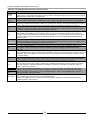
13.0 TROUBLE SHOOTING ................................................................................................................................ 46
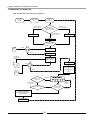
14.0 SEQUENCE OF OPERATION ..................................................................................................................... 50
15.0 INSTALLATION CHECKLIST...................................................................................................................... 51
16.0 ANNUAL MAINTENANCE AND INSPECTION........................................................................................... 52
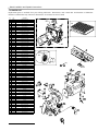
17.0 PARTS LIST................................................................................................................................................. 55
HAZARD SYMBOL DEFINITIONS
Danger Sign: Indicates a hazardous situation which, if not avoided, will result
in serious injury or death.
Warning Sign: Indicates a hazardous situation which, if not avoided, could
result in serious injury or death.
Caution Sign plus Safety Alert Symbol: Indicates a hazardous situation which,
if not avoided, could result in minor or moderate injury.
Caution Sign without Safety Alert Symbol: Indicates a hazardous situation
which, it not avoided, could result in property damage.
Notice Sign: Indicates a hazardous situation which, if not avoided could result
in property damage.
®
US Models
Matrix Installation and Operation Instructions
0.0 INTRODUCTION
General Installation Requirements
This document pertains to the correct installation and operation of NTI Matrix appliance, models numbers M100 and M100V. The
instructions detailed in this document supersede any and all previous instructions provided by NTI, written or otherwise. Each unit
is provided with the following:
1) Installation and Operation Instructions,
2) Matrix Users Manual, and
3) Natural to LP Conversion Kit *
* The conversion kit is required to convert the appliance so it will safely operate with Propane Gas.
Read and understand this entire document prior to proceeding with the installation of the Matrix. Failure
to follow the instructions outlined in this document will result in property damage, serious injury or
death.
User Responsibilities
This appliance must be installed and serviced by a qualified installer or service technician. This appliance must be serviced and
inspected annually when operating in normal residential applications. Demanding applications or extreme conditions (i.e.
commercial) may require more frequent service and inspection. As the User/Owner of this equipment, you are responsible for
ensuring the maintenance is performed at the required intervals. It is also the Users responsibility to ensure Vent and CombustionAir Intake termination is kept clear of ice and snow or any other obstruction. Failure to follow these instructions could result in
fire, serious injury, or death.
Failure to have the appliance properly serviced and inspected on a regular basis may result in property
damage, serious injury or death.
Failure to keep the Vent and Combustion Air Intake clear of ice, snow, and other debris may result in
property damage, serious injury, or death.
Installer Responsibilities
As the installing technician it is your responsibility to ensure the installation is performed in accordance with this instruction
manual as well as any applicable local or National installation codes. It is also your responsibility to inform the User/Owner of
their obligation with respect to the above description under “User Responsibilities”. Failure to follow this warning could result in
fire, serious injury, or death.
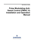
ATTENTION: LIQUEFIED PETROLEUM (LP) PROPANE
The Matrix is factory set to operate with Natural Gas. BEFORE OPERATING WITH PROPANE, the specified LP
Conversion Kit must be installed to convert the appliance so it will operate safely with LP Propane.
Liquefied Petroleum (LP) propane gas is heavier than air; therefore, it is imperative that your Matrix unit is not
installed in a pit or similar location that will permit heavier than air gas to collect. Local Codes may require appliances
fueled with LP gas be provided with an approved means of removing unburned gases from the room. Check your local
codes for this requirement.
NTI Series
Matrix
Natural to LP Propane Conversion Kit_
Model Number
Kit Number
M100, M100V
82650-1
Failure to use the appropriate Natural to LP Conversion Kit when operating the Trinity Lx with Propane
will result in extremely dangerous burner operation leading to property damage, serious injury or death.
Refer to section titled ATTENTION: LIQUEFIED PETROLEUM (LP) PROPANE for appliance
models and corresponding conversion kit numbers.
Appliance Vent / Air-Intake Piping
The Matrix is a “Direct Vent” appliance requiring a “Special Venting System”. Vent and CombustionAir Intake piping must be piped to the outdoors, using the vent material and rules outlined in these
instructions. Failure to follow instructions will result in serious injury or death.
2
Matrix Installation and Operation Instructions
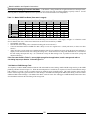
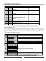
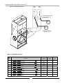
1.0 SPECIFICATIONS
Table 1.1 General Specifications
Model
CSA
Input
1,2
(MBH)
DOE
Heating
Capacity
1,3
(MBH)
136
136
Net
I=B=R
Rating
1,3
(MBH)
118
118
DOE
AFUE
3
(%)
Supply
Plenum
(inches)
Return
Plenum
(inches)
Airflow
Heating
(CFM)
Airflow
Cooling
(CFM)
Ventilation
(CFM)
Dimensions
H-W-D
(inches)
Vent/Air
4
Size
M100
25-150
95.1
22.5x18.5
18x18
400-1200 400-1600
53-28-38
3”
M100V
25-150
95.1
22.5x18.5
18x18
400-1200 400-1600
70-150
53-28-38
3”
Notes:
1 – Listed Input and Output ratings are at minimum vent lengths at Sea Level. Numbers will be lower with longer venting and/or altitudes greater then
2000 feet.
2 – The maximum output when operating on LP-Gas is limited to 145MBH.
3 – Based on rating plate input capacities, using standard test procedures prescribed by the U.S. Department of Energy. Ratings have been
confirmed by AHRI (GAMA).
4 – Matrix units require a special venting system, use only vent materials and methods detailed in these instructions.
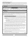
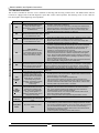
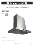
In Canada:
De-rate by 5% for altitudes between 2000
and 4500 feet. For altitudes above 4500 feet
consult with local authorities.
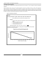
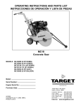
Figure 1.1 Maximum Capacity vs. Altitude
160
150
Input (Mbh)
1.1 High Altitude Operation
The Matrix is designed to operate to capacity
in installations at 2000 feet of elevation or
less. As elevations higher than 2000 feet
have less dense air, the unit is not capable of
providing its specified capacity. (See Chart).
140
130
120
In USA:
De-rate by 4% for every 1000 feet over 2000
feet.
110
0-2000
3000
4000
5000
6000
7000
8000
9000
10000
Elevation (ft)
CAUTION
AT ELEVATIONS GREATER THAN 2000 FEET, THE COMBUSTION OF THE MATRIX MUST BE CHECKED
WITH A CALIBRATED COMBUSTION TESTER TO ENSURE SAFE AND RELIABLE OPERATION. CONSULT
SECTION 5.20 FOR INSTRUCTIONS ON ADJUSTING THE INPUT TO PROVIDE PROPER OPERATION.
IT IS THE INSTALLERS RESPONSIBILITY TO CHECK THE COMBUSTION, AND
TO ADJUST THE COMBUSTION IN ACCORDANCE TO SECTION 5.20
3
Matrix Installation and Operation Instructions
2.0 INSTALLATION REQUIREMENTS
The installation of your NY Thermal Matrix gas furnace/boiler must conform to the requirements of your local authority, and the
National Fuel Gas Code ANSI Z223.1 and or CAN/CGA B149 Installation Codes. Where required by the Authority, the installation
must conform to the standard for “Controls and Safety Devices for Automatically Fired Boilers ANSI/ASME CSD-1.
IMPORTANT
Carbon Monoxide Detectors
Many jurisdictions require the installation of carbon monoxide detectors in buildings where a sidewall
vented fuel-burning appliance is installed. Installers must abide by local code requirements regarding the
installation of CO detectors. The use of a certified carbon monoxide detector is recommended but not
required by NTI.
IMPORTANT
“IN THE STATE of MASSACHUSETTS ONLY”
(a)For all horizontally vented gas fueled equipment installed in every dwelling, building or structure used in whole or in part
for residential purposes, including those owned and operated by the Commonwealth and where the side wall exhaust vent
termination is less than seven (7) feet above finished grade in the area of the venting, including but not limited to decks and
porches, the following requirements shall be satisfied:
1.
INSTALLATION OF CARBON MONOXIDE DETECTORS. At the time of installation of the side wall horizontal
vented gas fueled equipment, the installing plumber or gas fitter shall observe that a hard wired carbon monoxide
detector with an alarm and battery back-up is installed on the floor level where the gas equipment is to be installed and
on each additional level of the dwelling, building or structure served by the equipment. It shall be the responsibility of
the property owner to secure the services of qualified licensed professionals for the installation of hard wired carbon
monoxide detectors.
a. In the event that the side wall horizontally vented gas fueled equipment is installed in a crawl space or an
attic, the hard wired carbon monoxide detector with alarm and battery back-up may be installed on the next
adjacent floor level.
b. In the event that the requirements of this subdivision can not be met at the time of completion of installation,
the owner shall have a period of 30 days to comply with the above requirements; provided, however, that
during said 30 day period a battery operated carbon monoxide detector with an alarm shall be installed.
2.
APPROVED CARBON MONOXIDE DETECTORS. Each carbon monoxide detector as required in accordance with
the above provisions shall comply with NFPA 720 and be ANSI/UL 2034 listed and IAS certified.
3.
SIGNAGE. A metal or plastic identification plate shall be permanently mounted to the exterior of the building at a
minimum height of eight (8) feet above grade directly in line with the exhaust vent terminal for the horizontally vented
gas fueled heating appliance or equipment. The sign shall read, in print size no less than one-half (1/2) inch in size,
“GAS VENT DIRECTLY BELOW. KEEP CLEAR OF ALL OBSTRUCTIONS”. (A plate is included with the
boiler)
4.
INSPECTION. The state or local gas inspector of the side wall horizontally vented gas fueled equipment shall not
approve the installation unless, upon inspection, the inspector observes carbon monoxide detectors and signage
installed in accordance with the provisions of 248 CMR 5.08(2)(a)1 through 4.
(b)EXEMPTIONS: The following equipment is exempt from 248 CMR 5.08(2)(a)1 through 4:
1.
2.
The equipment listed in Chapter 10 entitled “Equipment Not Required To Be Vented” in the most current edition of
NFPA 54 as adopted by the Board; and
Product Approved side wall horizontally vented gas fueled equipment installed in a room or structure separate from the
dwelling, building or structure used in whole or in part for residential purposes.
…..Next Page
4
Matrix Installation and Operation Instructions
….Continued.
(c)MANUFACTURER REQUIREMENTS – GAS EQUIPMENT VENTING SYSTEM PROVIDED. When the manufacturer
of Product Approved side wall horizontally vented gas equipment provides a venting system design or venting system
components with the equipment, the instructions provided by the manufacturer for installation of the equipment and the venting
system shall include:
1.
2.
Detailed instructions for the installation of the venting system design or the venting system components; and
A complete parts list for the venting system design or venting system.
(d)MANUFACTURER REQUIREMENTS – GAS EQUIPMENT VENTING SYSTEM NOT PROVIDED. When the
manufacturer of a Product Approved side wall horizontally vented gas fueled equipment does not provide the parts for venting
the flue gases, but identifies “special venting systems”, the following requirements shall be satisfied by the manufacturer:
1.
2.
The referenced “special venting system” instructions shall be included with the appliance or equipment installation
instructions; and
The “special venting systems” shall be Product Approved by the Board, and the instructions for that system shall
include a parts list and detailed installation instructions.
(e)A copy of all installation instructions for all Product Approved side wall horizontally vented gas fueled equipment, all
venting instructions, all parts lists for venting instructions, and/or all venting design instructions shall remain with the appliance
or equipment at the completion of the installation.
ATTENTION
LIQUIFIED PETROLEUM (LP) PROPANE
The Matrix is set to operate with Natural Gas; LP Conversion Kit Part No. 82650-1 is included with each furnace and
must be installed before operating with Propane.
Liquefied Petroleum (LP) propane gas is heavier than air; it is imperative that your boiler is not installed in a pit or
similar location that will permit heavier than air gas to collect. Local Codes may require appliances fueled with LP gas
be provided with an approved means, of removing unburned gases from the room.
Check your local codes for this requirement.
2.1 Location
In all cases, the Matrix must be installed indoors, in a dry location, such that the gas components are protected from dripping or
spraying water or rain, during operation and servicing. The boiler location ambient temperature is maintained to a minimum of
50°F.
Determine the best location of the vent termination, and if possible locate the appliance as close to the termination point as possible.
Ensure that the desired appliance location is not subjected to flooding or high moisture levels, for damage to the appliance will
occur, voiding your NY THERMAL warranty.
IMPORTANT
CLEARANCES
For proper and safe installation adhere to the following clearances to combustibles:
Furnace Casing = 0"
Floor = Combustible
Flue Pipe:
Boxed in or enclosed = 2”
In free air = 0”
The following are the minimum clearances recommended for servicing:
Front = 24”
Sides = 24"
Back = 6"(optional return plenum location)
Bottom = 0”
5
Top = 12"
Matrix Installation and Operation Instructions
3.0 VENTING
The NY Thermal Matrix is a high efficiency condensing gas furnace/boiler utilizing induced power venting. Exhaust gases are to
be vented directly outdoors, using the venting method detailed in this section. Under no conditions, may this unit vent gases into a
masonry chimney, unless it is vacant, and utilizes Matrix approved venting material as illustrated in the figures in this section.
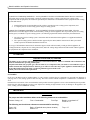
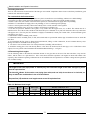
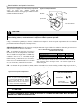
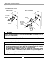
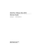
Attaching Vent Piping to Boiler
It is extremely important for the intake and exhaust piping to be adapted to the appropriate size immediately upon exiting the boiler
cabinet. The Matrix comes with a 3” male PVC fitting to connect the air intake port of the boiler. The Matrix exhaust connection
is 3” male PVC, use approved cement to connect to venting system. Check the flue outlet gasket for proper insertion and sealing
prior to and after attaching the venting. Ensure the venting system does not apply a load or stain on the flue outlet of the boiler
(recommend using two elbows to create a “swing joint” as shown above).
Figure 3.1 Venting Construction
It is recommended that two elbows be
used, so that the slope of the horizontal
exhaust vent does not affect the vertical
plumb of the pipe connected to the boiler.
Slope all horizontal indoor exhaust
venting ¼” to ½” per linear foot.
It is recommended to have a collection point
for condensation in the intake venting.
Condensation can then be drained to an
open house drain or condensate pump.
Drain line from intake must have an
appropriate trap or shut off valve to avoid
siphoning.
IMPORTANT
The vent connection and piping must be perfectly aligned to the furnace connection. AND MUST NOT
APPLY ANY WEIGHT OR LATERAL FORCE TO THE FLUE BOX. NTI does not warranty damages to the flue
box.
In Canada, the first 3 ft (915 mm) of vent piping must be readily accessible for inspection.
6
Matrix Installation and Operation Instructions
3.1 Vent/Air-Intake Pipe Material
Table 3.1 Acceptable Vent and Air-Intake Pipe Material
Installation Standards
Items 1
Materials 2, 3
Canada 4
United States
PVC - DWV
ANSI/ASTM D2265
All venting material in All plastic Vent materials
Vent Pipe and
installed on gas fired
PVC
Schedule
40
ANSI/ASTM
D1785
Canada must be
Fittings
ULC S636 approved. appliances in CAN/US must
CPVC Schedule 40
ANSI/ASTM F441
meet the Standards listed in
See Note 4 below for
PVC
ANSI/ASTM D2564
Pipe Cement
appropriate temperature Table 3.1. Failure to
CPVC
ANSI/ASTM F493
comply could result in fire,
applications.
serious injury or death.
Primers
PVC / CPVC
ANSI/ASTM F656
Notes:
1
Refer to Table 3.2 for Allowable Vent and Air-Intake Pipe Sizes and Lengths.
2
Closet/alcove installations in US and Canada require approved CPVC vent pipe, fittings, cements, and primers.
3
The Air-Intake does not require high temperature pipe material. Check applicable local codes for acceptable materials.
4
ULC S636 PVC is approved for flue gas temperatures up to 149oF (65oC) and must only be used for low temperature
applications. High temperature applications requiring appliance supply water temperatures greater than 140oF (60oC)
must use ULC S636 approved CPVC.
Mandatory Pre-commissioning Procedure for Plastic Venting
Do not apply power to the appliance prior to Step 4 in the Mandatory Pre-commissioning Procedure for
Plastic Venting.
1.
2.
3.
4.
5.
6.
Working with the power turned off to the appliance, completely install the vent and air intake system, securely cementing
joints together. If possible, allow primers/cements to cure for 8 hours before firing the burner. If curing time is less than 8
hours, proceed with Steps 2 through 6.
Maintain the appliance gas supply shut-off valve in the off position.
Disconnect electrical leads to the Hot Surface. Ensure the cables are placed in a fashion where they will not arc to ground or
other conductor.
Turn power on to the appliance and apply a heat demand.
Allow for 3 complete trials for ignition, consisting of pre and post purge of the combustion blower, until an ignition lockout
occurs. Repeat the process two more times (i.e. 9 complete ignition sequences in total).
Turn power off and reconnect the electrical leads to the Igniter.
7
Matrix Installation and Operation Instructions
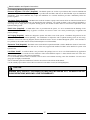
3.2 Venting Configurations
3.2.1 Two-Pipe Vent Termination
Figure 3.2 Two-Pipe Vent Termination
Exhaust
Window
The vertical portion of the exhaust
termination does not require insulation,
if less than 5 feet in total length
Apply Plate
Gas Vent Directly Below
Keep Free of Obstructions
18” Min
Coupling
and
elbow to be
against wall
– ½” play is
acceptable
Intake
12” Plus Snow allowance
Example 12+19=31”
Exhaust
36”
Exhaust
18”
Intake
Must insert
plastic bird
screen
4”-12” or greater
than 36”
Outside Wall”
Intake
12” Plus Snow
Allowance Min”
3.2.2 Concentric Vent Termination (No longer approved for Canada)
Figure 3.3 Concentric Vent Termination
Apply Plate Here
Support
(Field installed)
Gas Vent Directly Below
Keep Free of Obstructions
Inlet air
Exhaust
Inlet air
48” min.
36” min.
Note: inlet pipe must always
be connected to the boiler.
4” or greater
than 24”
Minimum 12”
plus
snow
allowance
Must insert
plastic bird
screen
Use NTI part # 82666 or York part # 1CT0303
Instructions included with vent terminal contain more detailed assembly and installation instructions.
Clearances and requirements of this manual supersede those of the instructions included with the vent terminal.
Terminal must be cemented together during installation.
8
Exhaust
Must be 1”
from wall
Matrix Installation and Operation Instructions
3.2.3 Roof Venting
Exhaust
Figure 3.4 Roof Venting
Inlet Air
24”
Roof weather seal
Flashing (field supplied)
18”
12” Plus
Snow
Support
(Field supplied)
Inlet Air
Exhaust
IMPORTANT
USE OF EXISTING CHIMNEY
It is permissible to run vent pipe through an existing chimney as long as:
1.
2.
3.
4.
The chimney is not to be used by any other appliance.
Flue gases don’t enter the vacant chimney.
Only Trinity certified venting materials are used, see Section 3.1.
Vent lengths are within the maximums specified.
9
Note: inlet pipe must
always be connected
to the boiler.
Matrix Installation and Operation Instructions
3.3 Venting Rules and Guidelines
1. It is highly recommended that the vent terminal be located where it will not be exposed to normal prevailing winds.
2. The exhaust must be a minimum of 18” above the air inlet, and the air inlet must always be a minimum of 12” plus snow
allowance above any surface that will support snow. (Two feet plus snow allowance is highly recommended). Consult your weather
office for the maximum typical snowfall for your region. Example: New Brunswick Canada the typical maximum snowfall is 19”,
Thus in figures of Section 3.3, the inlet must be (12”+19”) = 31” off the ground, the exhaust must be (31”+18”) = 49”.
3. Under normal operating conditions this appliance will produce a plume of white gases, and should be taken into consideration
when selecting an adequate location. A 3’ diameter stainless, plastic, or vinyl shield can be used to flash the exterior of the
residence.
4. If the horizontal distance between the inlet and exhaust is more then 12”, increase minimum vertical separation by the same
amount. (If horizontal distance is greater then 6’, no additional vertical spacing is required). Example, horizontal separation equal to
24” requires a minimum vertical separation of 18”+(24”-12”) =30”. (Vertical separation is never required to be greater then 36”)
5. Elbows on outside of wall must be no greater than ½” away from the wall.
6. All indoor exhaust piping must be on a slope back to the boiler a minimum of ¼” per linear foot of vent. For applications where
excessive condensation is possible ½” per linear foot is recommended. (See illustration in Figure 3.1)
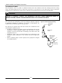
6. Exhaust vent pipe can be secured to the wall for more rigidity.
7. In all roof applications the discharge must point away from the pitch of the
roof.
Figure 3.5 Installing Venting Below Grade
8. Install adequate flashing where the pipe enters the roof, to prevent water
leakage.
9. Install and seal a rain cap over existing chimney openings, in vacant
chimney applications.
10. For installations that exit the wall below grade. Excavate site as shown in
Figure 3.5, to a point below where the pipes are to exit. Ensure that the wall is
fully sealed where the pipes penetrate the wall. The vent piping MUST be
secured to the side of the building above grade, as shown, to provide rigidity.
NTI provides a mounting bracket, PN:82075, for securing the exhaust pipes.
Ensure that the vent clearances are maintained (Inlet minimum 12” plus snow
allowance from grade, exhaust outlet 18” minimum above inlet)
11. Install the vent screens provided into both the inlet and exhaust vent
terminal elbows. The screen must be on the outside of the last elbow. Install
the screen into the female opening of the elbow. Then cut a small piece of
pipe to sandwich the screen into the elbow. NOTE be sure that the small piece
of pipe cut, does not extend past the end of the elbow. Two screens are provided in the package.
12. It is extremely important that the intake and exhaust piping be adapted to the appropriate size immediately upon exiting the
boiler cabinet.
13. All interior vent pipe shall be supported a minimum of every 36”.
10
Matrix Installation and Operation Instructions
3.4 Venting Clearances
These are code restrictions for the location of the Flue gas vent terminal. Compliance doesn’t insure a satisfactory installation; good
common sense must also be applied.
The vent terminal shall not terminate:
1. Directly above a paved sidewalk or a paved driveway that is located between two buildings, and that serves both buildings;
2. Less than 7 feet above grade where located adjacent to a paved walkway or driveway located on public property.
3. Within 3' (three feet) of a window or door that can be opened, or non-mechanical air supply inlet to any building.
4. Within 6’ of a mechanical air supply inlet to any building, or roof eve containing soffit openings.
5. Above a meter/regulator assembly within 3' horizontally of the vertical centerline of the regulator.
6. Within 3' horizontally of any gas service regulator vent outlet up to a height of 15’.
7. Less than 30” plus snow allowance above grade, or any surface that will support snow, ice, or debris. The exhaust must be a
minimum of 18” above the air inlet, and the air inlet must always be a minimum of 12” plus snow allowance above any surface that
will support snow. (Two feet plus snow allowance is highly recommended). Consult your weather office, for the maximum typical
snowfall for your region.
8. Underneath a wooden verandah, porch, or deck.
9. Underneath cement verandah, porch, or deck, unless both ends are open and the exhaust pipe is installed at least 24” under the
deck floor.
10. So situated that the flue gases are directed towards brickwork, siding, or other construction, in such a manner that may cause
damage from heat or condensate from the flue gases.
11. Less than 3’ from an inside corner of an L-shaped structure (including walls and fences).
12. Install the warning plate “Gas Vent Directly Below” 4 feet above the location of the air inlet pipe, so it is visible from at least
eight (8) feet away (Plastic Label included in the Installation Manual Package – see figure).
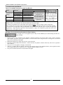
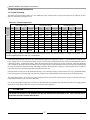
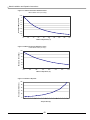
3.5 Determining Vent Lengths
Use the following chart to determine the maximum amount of vent pipe that can be used. This chart calculates, sweep and 45º
elbows, and 90º elbows at 5 equivalent feet. Note: chart shows allowable equivalent vent lengths for intake and exhaust vents
separately, thus an M100V operating on Natural Gas can be installed with 105 equivalent feet of intake venting and 105 equivalent
feet of exhaust venting.
IMPORTANT
The length of one vent pipe (intake or exhaust) may not exceed the length of the other vent pipe by more
then 20 equivalent feet.
The three 90° elbows of the exterior vent piping (two outlet, and one inlet) do not have to be included, as
they are taken into consideration in the vent calculations.
Propane Gas (LP) maximum vent length cannot exceed 50 equivalent feet.
Table 3.2 Maximum Vent Length
Model
M100
M100V
Vent
Size
Gas
Max. Equiv.
Length
1
3"
Natural
105
3"
LP
50
2
Number of Elbows or 45's
3
4
5
6
7
8
9
100
95
90
85
80
75
70
65
60
45
40
35
30
25
20
15
10
5
11
Matrix Installation and Operation Instructions
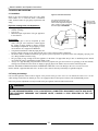
3.6 Outdoor Venting
Vent piping outside the building is permitted under the following
conditions:
o The maximum length outside the building is 20 feet. (Outdoor
length must be included in the overall vent length calculation.)
o All normal termination clearances are maintained.
o All exterior exhaust vent pipes are insulated with 3.5”-ID, ½”thick, Closed Cell Foamed Polyolefin Tubing i.e., “Tundra
Seal Plus” or equivalent.
o The pipe is supported every 24”
o The exhaust and inlet are sloped back to the boiler ½”
elevation for every foot.
Figure 3.6 Outdoor Venting
Supports every 24”
Exhaust
Inlet
Apply Plate Here
Gas Vent Directly Below
Keep Free of Obstructions
12
Maximum of 20 feet
is
permitted
for
outside a building
using 3” pipe ONLY.
12” plus allowance above
grade for snow
Matrix Installation and Operation Instructions
4.0 CONDENSATE DRAIN
This unit produces water as a product of combustion. Much of this water condenses on the heat exchanger and in the venting
system. All exhaust piping must be on a slope back to the boiler ¼” per linear foot of vent. Steps must be taken to ensure that
condensate does not collect in the venting system. Condensate must be drained from the boiler into a household drain.
WARNING
FAILURE TO PROPERLY CONNECT THE CONDENSATE LINE WILL CAUSE COMBUSTION GASES TO
ENTER THE ROOM, POSSIBLY CAUSING SERIOUS INJURY TO OCCUPANTS OR DEATH.
Note: check with your municipality, or local gas company to determine if disposal
of combustion condensate is permitted. In the State of Massachusetts the
condensate must be neutralized prior to entering a drain.
The following are important notes that must be taken into consideration when
constructing the condensate system:
o DO NOT run condensate line outside. A frozen or blocked drain will cause the
condensate to fill the combustion chamber. This will result in a no heat
condition, as the unit will shut down, and damage to the flame sensor, and
components can occur.
o NEVER use copper, steel, or galvanized piping in the construction of the
condensate system (condensate is very corrosive and will wrought most
metals).
o When a condensate pump is used or required, select a pump that is designed
for residential furnaces.
Figure 4.1 Condensate Drain Plumbing
Condensate
Drain From
Boiler
Nipple must
be cut.
Drain must be
open to allow
overflow if
blocked
Drain must
include trap
13
Matrix Installation and Operation Instructions
5.0 INSTALLING GAS PIPING
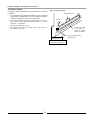
5.1 Installation
Refer to the current National Fuel Gas Code ANSI
Z223.1/NFPA 54 or CAN/CGA B149.1 installation
codes, and local codes for gas piping requirements and
sizing.
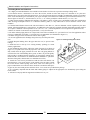
Figure 5.1 Gas Inlet Connection
It is highly recommended to use
flexible gas pipe, the gas valve and
blower cannot support the weight of
piping. If piping is used, ensure that
the valve supports NO WEIGHT
Pipe size running to the unit depends on:
o Length of pipe.
o Number of fittings.
o Type of gas.
o Maximum input requirement of all gas appliances
in the residence.
Gas cock shut
Off Valve to be
"T" type handle
Gas valve
Ensure that:
o Flexible gas pipe is used (if acceptable by local
codes). The gas valve and blower cannot support
the weight of piping, leading to blower vibration
and damaged components. If rigid piping is used,
ensure that the valve supports NO WEIGHT
o You plan the installation so that the piping does not
interfere with the vent pipe, or the removal of the valve, burner, and serviceable components.
o The Boiler shall be installed such that the gas ignition system components are protected from water (dripping, spraying, rain
etc.) during installation and servicing.
o The gas piping is large enough for all the appliances in the home. No appreciable drop in line or manifold pressure should
occur when any unit (or combination of units) lights or runs.
o Always use a pipe-threading compound that is resistant to propane (LP) gas solvent action. Use sparingly to all male threads,
starting at two threads from the end. Over doping or applying dope to the female end, can result in a blocked gas line.
DO NOT TIGHTEN FITTINGS WITHOUT SUPPORTING THE GAS VALVE as damage to the valve or motor can occur.
Install a manual “equipment Shut-Off Valve” as shown. Valve must be listed by a nationally recognized testing lab.
5.2 Testing and settings
Gas line and regulator(s) must be able to support a line pressure at the gas valve of 4-9”w.c for Natural Gas and 9-12”w.c for LP
while running at maximum rate. Matrix gas valves are equipped with two bleed ports to measure Line and Manifold pressure.
Note: Line pressure adjustments can only be made at the gas regulator, NOT AT THE GAS VALVE.
WARNING
IF LINE PRESSURE EXCEEDS ½ PSI (14 INCHES W.C.) COMPLETELY DISCONNECT LINE TO GAS VALVE.
THIS EXCESSIVE PRESSURE CAN DAMAGE VALVE, CAUSING A LEAK RESULTING IN FIRE OR
EXPLOSION.
14
Matrix Installation and Operation Instructions
Figure 5.2 Setting Combustion
Manifold
Input Screw
out
The gas valve is equipped with a throttle/input adjustment
screw. The input screw “MUST NEVER BE
ADJUSTED” without verifying proper combustion with a
calibrated combustion analyzer.
Gas IN
Air In
Line Pressure
CAUTION
The Matrix is tested with Natural Gas having a heating value of 1020 BTU per cubic foot. For areas with
lower heating values, a combustion test is required to obtain optimum operation.
Using a calibrated flue gas analyzer, check the combustion and compare it with the acceptable requirements. The test should be
performed at maximum fan speed (“Gas Input Value”).
Adjusting Combustion - Use the input screw to adjust the amount of gas available for combustion. Increasing gas increases CO
and CO2. Reducing gas decreases CO and CO2.
CO – At maximum fan speed, the CO reading is
the most critical to the safe operation of the boiler.
The CO should be no higher than 175 PPM at any
condition. If the CO is over 140 PPM, the input
should be reduced until the CO is less than 140
PPM or the CO2 is reduced to 8% (9% for LP Gas).
If the CO is over 140 PPM and the CO2 is less than
8% (9% for LP Gas), contact NTI for assistance.
Table 5.1 Normal Range of Combustion Products
(At maximum fan speed, 240)
Carbon Dioxide CO2 %
Carbon Monoxide CO ppm
NOX ppm
Natural
8-9.5*
25-175*
10-50
Propane
9-10.5*
25-175*
10-50
*Note: On colder days CO2 should be closer to the lower number, on warmer
days it should be closer to the higher number. CO should be highest at the
maximum firing rate.
CO – At minimum fan speed, should be checked, and the CO should be less than the reading recorded at high fan speed. The CO2
at low fan speed must not be at least as high as the CO2 recorded at high fan speed, but not more then 9.5% (10.5% for LP Gas).
Figure 5.3 Gas Input Screw Adjustment
Input Screw Adjustment
Decrease gas
Turn Clockwise
Input Screw – Is a multiple turn needle
valve. Fully open to close is approximately
17 turns. Typical adjustment for Natural
Gas is 0-1 full turns in or out. Typical
adjustment for LP Gas is 0-3 full turns in
or out (after conversion is performed).
Increase gas
Turn counterclockwise
ATTENTION
IF FOR ANY REASON THE INPUT SCREW IS ADJUSTED, A “COMBUSTION ANALYZER” MUST BE USED TO
ENSURE SAFE AND PROPER OPERATION.
15
Matrix Installation and Operation Instructions
6.0 BOILER PLUMBING
WARNING
THIS APPLIANCE CONSISTS OF A “LOW-MASS” BOILER AND MUST HAVE ADEQUATE WATER
FLOWING THROUGH IT WHENEVER THE BURNER IS ON. FAILURE TO DO THIS WILL DAMAGE
THE UNIT AND VOID THE WARRANTY. PLUMBING MUST INCORPORATE A PRESSURE
REGULATING FILL VALVE AND PRESSURE RELIEF VALVE.
WARNING
HYDRONIC SYSTEMS, OLD AND NEW, MUST BE FLUSHED TO REMOVE SEDIMENT, FLUX,
FILINGS, ETC. FAILURE TO DO SO WILL SERIOUSLY DAMAGE THE BOILER, VOIDING
WARRANTY. (CLEAN WITH FERNOX CLEANER F3, NTI PART NUMBER: 83449.)
WARNING
WATER WITH A TOTAL HARDNESS GREATER THEN 100PPM (6 GRAINS/GALLON) MAY RESULT
IN HEAT EXCHANGER FAILURE AND WILL VOID YOUR NTI WARRANTY. TREAT ALL SYSTEMS
WITH FERNOX PROTECTOR F1 (NTI PART NUMBER: 83448), WHICH IS INCLUDED WITH THE
MATRIX PACKAGE.
WARNING
THE BOILER FITTINGS CAN’T SUPPORT ANY WEIGHT. SUPPORT ALL OF THE PLUMBING
SYSTEM EXTERNALLY.
DO NOT APPLY TORQUE TO THE PLUMBING FITTINGS. HOLD THE FITTING WHEN INSTALLING,
OTHERWISE DAMAGE TO THE UNIT WILL OCCUR.
CAUTION
This appliance is designed to operate in residential and commercial heating systems, and is not intended
for:
1. Outdoor installations, or unheated spaces, which can cause freezing.
2. Process heating of potable water, or any other fluids.
3. Un-pressurized, and gravity feed heating systems.
4. Heating systems with very low pressures or flow.
IMPORTANT
1.
2.
3.
4.
Understand and follow the plumbing requirements provided in this section.
Keep serviceability in mind when installing plumbing around the furnace cabinetry.
Install fittings that will allow the system to be flushed if needed during annual check-ups.
Add inhibitor, Fernox Protector F1 (NTI Part Number: 83448), to the system water to help prevent
limestone and magnetite deposits, and galvanic corrosion. Bottle provided will treat an average 100liter (26 US gallon) system.
16
Matrix Installation and Operation Instructions
6.1 Plumbing (Minimum Requirements)
Pressure Regulator “Fill Valve” (Supplied): The Matrix operates as a boiler to provide heat, thus it must be installed and
operated as such. A 12-15 PSI pressure regulator is provided with the Matrix and must be field installed as per the installation
instructions. Note: Local authorities may require the installation of a certified “back-flow preventer” immediately before the
pressure regulator.
Circulating Pump (Supplied): The Matrix has a built-in circulator to pump water from the boiler to either the internal forcedair heating coil or the internal domestic coil (brazed plate heat exchanger). An external circulator is only required if the Matrix is
also being used to supply heat to a hydronic heating system, the external circulator must be sized for the requirements of the
hydronic heating system.
Relief Valve (Supplied): A 30PSI Relief Valve is provided with the system, it is to be mounted with the discharge in the
horizontal. Ensure that the discharge is piped to a location were steam or water won’t cause personal injury or appliance and
property damage.
Air Purging (Supplied): Boilers are designed to operate with airless water in the system. The Matrix design allows for the
evacuation of air from the internal plumbing. For installations in conjunction with a hydronic heating system an Air Scoop,
installed as shown in the following diagrams, must be installed to remove air as it circulates through the system. If air continues to
be a problem an air scrubber must be used (recommend Spirovent # VJR 100TM).
Expansion Tank (Supplied): The Matrix comes with a built-in expansion tank that is sized to handle the volume of water in the
Matrix unit. An external expansion tank must be field sized, supplied and installed for Matrix units installed in systems with
hydronic heat.
Low Water Cutoff: A certified LWCO is not provided in the package, however one is to be field installed in any application
where the Matrix boiler is located above the radiation or where local authorities require it. Ensure that the water line of the “Low
Water Cutoff” is at least 6” above the top of the boiler.
It is recommended that the LWCO be situated so that it can be tested without removing water from the Matrix. Tri-cocks and a
gauge glass are highly recommended.
NTI recommends against the installation of isolation valves between the LWCO and the Matrix.
Use the normally open contacts of the LWCO to break 24V to the burner circuit (See Wiring Diagram).
CAUTION
DAMAGE WILL OCCUR IF THE BOILER IS FIRED WITH NO WATER IN IT, OR REPETITIVE NO
FLOW OPERATIONS, WHICH WILL VOID THE WARRANTY.
17
Matrix Installation and Operation Instructions
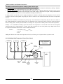
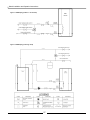
6.2 Matrix Boiler Connections
Figure 6.1 Boiler Feed Water Connections
Standard Configuration
Optional (Hydronic Add-On)
Relief Valve
(supplied)
Relief Valve
(supplied)
Boiler Feeder
Valve (supplied)
Air Scoop
Backflow
Preventer
Hot Supply
Boiler Feeder
Valve (supplied)
Drain Valve
Cold Return
Backflow
Preventer
Expansion Tank
IMPORTANT
Expansion tank and air removal device for the internal functions of the Matrix are included and provide only
enough capacity for these functions.
Additional secondary systems require appropriately sized air removal and expansion capability.
6.3 Hydronic Heating Additions (Optional)
ATTENTION
1. LOW TEMPERATURE APPLICATIONS (i.e., In-floor) require the use of mixing controls such as a Tekmar
injection system or thermostatic mixing valves (See 6.2.3 to 6.2.4). During a call for “Forced-Air Heat”
the Matrix will operate at a constantly varying boiler water temperature, this temperature may at times
exceed the maximum allowable temperature for some or all of the hydronic zones.
2. HI TEMPERATURE APPLICATIONS (i.e., finned tube baseboard) do not require mixing controls,
however, when the Matrix is operating during a call for Forced-Air Heat the hydronic system will only
receive the heat leftover from the Matrix air handler; keep this in mind during system sizing and design.
3. In applications that do not use zone valves it is important to incorporate into the system design means
necessary to prevent THERMAL SIPHONING. Note: the following drawings are to be used as a reference
only for the system designer.
18
Matrix Installation and Operation Instructions
The Matrix provides heat to hydronic heating systems in two ways:
1. Hydronic Call (24 VAC @ H without a call for forced air heating) – A boiler demand is initialized by sending a ‘Hydronic
Demand’. The boiler will then maintain a set point of ‘HYD’ (See Table 9.3).
2. Hydronic Shared Call (24 VAC @ H concurrent with a forced air call) – With this demand the forced air system is given
priority. The set point temperature will be the higher of the ‘HYD’ setting or the forced air set point. During a shared call the
hydronic system can only receive the water temperature returning from the fan coil.
If, during a shared call, the boiler can not supply enough heat to maintain a minimum plenum air temperature of 95°F, the Fan
Controller will shut-off the hydronic loop using the N.O/N.C contacts on the terminal board until the forced air temperature
recovers.
The Matrix has a Grundfos 15-42 built into the primary loop. Given the head loss of the primary loop, the flow rate is fixed at 5
gpm. When designing any secondary heating system it is important to allow for an increase boiler set point to ensure full capacity
of the secondary system. This may necessitate the use of mixing valve to protect the secondary from elevated water temperatures.
Example: For a 75,000 Btu/hr secondary system with a desired water temperature of 110°F and 20° ∆T the flow rate will required
is BTU/hr/(500* ∆T) or 75,000/(500*20) = 7.5 gpm. Since this exceeds the flow rate in the primary loop, a higher boiler ∆T will
be required to maintain the desired 110°F. This is calculated as follows:
∆Tboiler
= ∆Tsecondary* gpmsecondary/gpmprimary
= 20*7.5/5
= 30°F
Adding the ∆Tboiler to the return water temperature of 90°F (110°F-20°F) gives a required ‘HYD’ set point of 120°F.
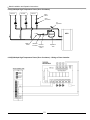
6.3.1(A) Multiple High Temperature Zones (Zone Valves)
Zone #3
Zone #2
Zone #1
High Temperature
Zones Only
Zone
Valve
System
Circulator
Air
Separator
NTI
Make Up
Water
Backflow
Preventer Pressure
Reducing
Valve
Expansion
Tank
19
Matrix Installation and Operation Instructions
6.3.1(B) Multiple High Temperature Zones (Zone Valves) – Wiring w/ Zone Controller
6.3.1(C) Multiple High Temperature Zones (Zone Valves) – Wiring w/o Zone Controller
20
Matrix Installation and Operation Instructions
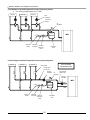
6.3.2(A) Multiple High Temperature Zones (Zone Circulators)
Zone #3
Zone #2
Zone #1
Check
Valves
Zone
Circulators
Air
Separator
NTI
Make Up
Water
Backflow
Preventer Pressure
Reducing
Valve
Expansion
Tank
6.3.2(B) Multiple High Temperature Zones (Zone Circulators) – Wiring w/ Zone Controller
21
Matrix Installation and Operation Instructions
6.3.3 Multiple Controlled-Temperature Zones (Tempering Valves)
•
Use wiring configuration in 6.3.2(B)
Temp #2
Temp #3
Temp #1
Zone
Circulators
Tempering
Valves
M
Air
Separator
H
M
M
H
C
H
C
C
NTI
Make Up
Water
Backflow
Preventer Pressure
Reducing
Valve
Expansion
Tank
6.3.4(A) Single Controlled-Temperature Zones (Injection System)
Zone #3
Zone #2
Zone #1
One Controlled
Temperature Only
Zone Valves
Temperature
Sensor (S1)
System
Circulator
Temperature
Sensor (S3)
Air
Separator
Injection
Circulator
NTI
Make Up
Water
Backflow
Preventer Pressure
Reducing
Valve
Expansion
Tank
22
Matrix Installation and Operation Instructions
6.3.4(B) Single Controlled-Temperature Zones (Injection System) – Wiring Tekmar 356
6.3.5 Multiple Controlled-Temperature Zones (Injection System)
Low Temp. Zones
High Temp Zones
Multiple Controlled
Temperatures
Temperature
Sensors
System Circulators
Injection
Circulators
Boiler
Circulator
Air
Separator
NTI
Make Up
Water
Backflow
Preventer Pressure
Reducing
Valve
Expansion
Tank
23
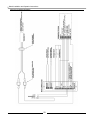
Matrix Installation and Operation Instructions
7.0 Domestic Hot Water System
7.1 DHW Description of Operation
The Matrix heats domestic hot water on demand, indirectly, using a brazed plate heat exchanger. Using an internal flow meter, the
Matrix recognizes a DHW demand when the DHW flow rate is greater then 0.4gpm. The Matrix immediately goes into domestic
mode, regardless of what other systems may have been operating, the burner fires and the Matrix attempts to achieve a calculated
set point which depends on the sensed water flow rate and the programmed H20 setting (See Section 9.2.1). The H20 setting is
accessed via the menu in the Matrix Fan (blue) controller, and should be set at a value equal to (or slightly greater) than the
temperature required at the hot water fixtures, e.g. 125ºF. The Fan control will communicate to the Boiler (red) controller a boiler
water temperature set point applicable for the sensed flow rate and the H20 setting selected. The higher the flow rate and/or H20
setting, the higher the boiler water set point (boiler water setting will not exceed the H20 setting by more then 30ºF). NTI provides
a Thermostatic Mixing Valve adjustable from 100 to 145°F; the mixing valve shall be installed between the Matrix DHW supply
fitting and the hot water supply pipe to the fixtures (See Figures 7.1 and 7.2), thus providing user protection from scalding hot
water. Note: code requirements may require the maximum setting to be fixed at 120°F, see “Thermostatic Mixing Valve” below
and the instructions included with the valve.
7.2 DHW System Plumbing & Set-up
DHW Inlet & Outlet Connections: The Matrix has two potable water connections, Inlet & Outlet, which exit the left side of
the Matrix Cabinet; on the inside of the cabinet the two lines are connected to the Brazed Plate Heat Exchanger. The cold Inlet line
flows through an integrated brass flow meter before connecting to the rear fitting of the Brazed Plate Heat Exchanger. The hot
Outlet line flows directly from the front fitting of the Brazed Plate Heat Exchanger. See Figures 7.1 and 7.2 for installation details
Thermostatic Mixing Valve: A Sparcomix AM101-US-1 is provided with your package. This valve regulates the water
temperature leaving the plate heat exchanger, and must be used in every instance. The dial can be set to the desired temperature
required. Consult the Honeywell manual SD/IS150 for detailed instructions and settings. (Note: the valve must be set to a supply
temperature of not more then 120˚F. It is the responsibility of the installer to set the valve and remove the dial.)
WARNING
IF THE ANTI-SCALD VALVE IS NOT INSTALLED TO THE HONEYWELL SHEET ‘SD/IS150’, AND THIS
MANUAL, OPERATION MAY SUPPLY SCALDING HOT WATER TO THE OCCUPANTS.
Y-Strainer (Supplied): To protect the Matrix’s internal flow meter, it is important to install the factory supplied Y-Strainer in
the location shown in Figures 7.1 and 7.2; dirt and other debris can cause the flow meter to malfunction.
Check Valve: A check valve must be field provided and installed on the outlet of the mixing valve to prevent expansion devises
down stream from back flowing when the water pressure drops during cold water draws. Failure to prevent the backflow will cause
water to flow forward through the flow switch, activating it, when the cold-water draw has ended and the water pressure increases.
Throttling Valve: Installed a throttling valve, after the mixing valve, to regulate the maximum hot water flow rate. The Matrix is
limited to a firing rate of 150MBH; therefore excessive flow rates will result in cooler hot water temperatures.
Drain and Isolation Valves: Install drain and isolation valves on the inlet and outlet of the brazed plate heat exchanger, as
shown in Figures 7.1 and 7.2 so it can be flushed free of possible build-up caused by dirt or hard water.
Hard Water: To prevent the formation of scale on the inside of the brazed plate heat exchanger and other components in the
domestic hot water system, water with hardness higher than 50 ppm Calcium Carbonate must be treated with a “Water Softener”
prior to entering the appliance. Plugging of the domestic system by scaling or accumulation of dirt is not the responsibility of NY
Thermal Inc., and suitable steps shall be taken to avoid it.
24
Matrix Installation and Operation Instructions
Cleaning: Brazed plate heat exchangers operate with high turbulence flow, even at low flow rates. This high turbulence keeps
small particles in suspension minimizing fouling and scaling. However, in some applications the fouling tendency can be very
high, e.g. when using extremely hard water at high temperatures. In such cases it is always possible to clean the exchanger by
circulating a cleaning liquid. Use a tank with weak acid, 5% phosphoric acid or, if the exchanger is frequently cleaned, 5% oxalic
acid. Pump the cleaning liquid through the exchanger. For optimum cleaning, the cleaning solution flow rate should be a minimum
of 1.5 times the normal flow rate, preferably in a back-flush mode. After use, do not forget to rinse the heat exchanger carefully
with clean water. A solution of 1-2% sodium hydroxide (NaOH) or sodium bicarbonate (NaHCO3) before the last rinse ensures
that all acid is neutralized. Clean at regular intervals.
7.2.1 Instantaneous DHW (w/o Storage Tank)
The Matrix will provide domestic hot water continuously when flow is sensed by the flow meter. This method is the most efficient
means of heating water by allowing the boiler to operate at a lower return water temperature, thus increasing combustion efficiency,
and by minimizing standby losses. See Figure 7.1 for installation details.
DHW Limitations: As the Matrix produces domestic hot water instantaneously; there are inherent limitations of the system:
o NO STORAGE - As there is no water storage, the boiler can only provide water at the temperature specified at the
corresponding flow rates. Flow through the fixtures must be regulated so not to exceed the ability of the boiler to heat the
water. MORE FLOW = LESS TEMPERATURE. See Table 7.1 and “Procedure for Setting up Domestic Hot Water”.
o DOESN’T MAINTAIN TEMPERATURE – When there is no call for domestic the unit is off. From a dead stop the unit will
detect flow and start providing heat in 15 seconds, and be up to capacity by 25 seconds. Once running, the unit can provide an
endless amount of hot water. If the flow is momentarily turned off for whatever reason, the unit will turn off. Once off, the unit
must relight, and not provide heat for 45-75 seconds. This will cause cold unheated water to pass through the unit, and advance
through the domestic plumbing between the previously heated (hot) water, and the new (hot) water. This can be mistaken for
an inability to adequately heat the water.
“Storage”Feature (St0): For improved domestic hot water comfort, the Matrix incorporates a “Storage” feature. This storage
feature, when enabled, will keep the boiler water hot for a period of 1 to 24 hours following a call for domestic hot water (See
Section 9.2.1 for setting). When the boiler water drops below 140°F the boiler will fire and bring the boiler to 180°F before
shutting off. This “Storage” feature helps in reducing the wait time associated with a tankless hot water system. In systems where
a storage tank is used (See Figure 7.2), this feature should be disabled, e.g. set to OFF.
25
Matrix Installation and Operation Instructions
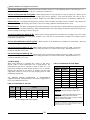
Procedure for Setting up Domestic Hot Water: If the Matrix is being installed in an application that uses municipal water,
often the pressure is high enough to generate flow rates at the faucets that will exceed the appliances capacity to heat it. See the
following table to determine what flow can be expected at various inlet and outlet water temperatures.
Outlet Water (F)
Table 7.1 Matrix DHW Flow Rates (flow rates in usgpm)
110
115
120
125
130
135
140
40
3.9
3.6
3.4
3.2
3.0
2.8
2.7
45
4.2
3.9
3.6
3.4
3.2
3.0
2.8
Inlet Water Temperature (deg. F)
50
55
60
4.5
4.9
5.4
4.2
4.5
4.9
3.9
4.2
4.5
3.6
3.9
4.2
3.4
3.6
3.9
3.2
3.4
3.6
3.0
3.2
3.4
65
6.0
5.4
4.9
4.5
4.2
3.9
3.6
70
6.7
6.0
5.4
4.9
4.5
4.2
3.9
To avoid having too much flow at the faucets use the throttling valve located at the “Cold Supply” in Figure 7.1 to limit the overall
flow of domestic hot water. Follow these instructions to achieve the best delivery of DHW:
o Open throttle valve fully.
o Turn the dial on the mixing valve to the desired setting (do not exceed 120˚F).
o Create the maximum amount of DHW flow that is likely to occur on a regular basis. (Usually tub faucet, or choose two other
faucets)
o Allow the boiler to reach steady state, and then throttle the shut-off valve until the hot water exiting the plate heat exchanger is
slightly warmer than the mixed water exiting the mixing valve. Ensure the boiler is firing at the maximum rate, if not increase
the H20 setting and repeat this step. (It is beneficial to keep the H20 setting as low as possible to limit short cycling and
maintain efficiency)
If the flow rates listed in Table 7.1 are not high enough for the application, install a storage tank with recirculating loop as per Section 7.2.2 and Figure 7.2.
7.2.2 Matrix w/ DHW Storage Tank
To completely avoid the DHW limitations inherent with on demand hot water heating, install a DHW storage tank as per the DHW
plumbing schematic shown in Figure 7.2. When the tank temperature is insufficient, an aqua-stat (T-stat) located within the storage
tank completes a 120VAC circuit to a potable (bronze or Stainless Steel) circulating pump. The pump circulates water from the
bottom of the storage tank (typical location of a drain fitting) to the DHW inlet fitting of the Matrix (Rear fitting to the Flow Meter
and Brazed Plate Heat Exchanger). The Matrix Flow Meter senses the water flow and triggers a DHW demand; heated water flows
from the Matrix and enters the inlet fitting of the storage tank.
26
Matrix Installation and Operation Instructions
Figure 7.1 DHW Piping (Tankless – On demand)
Figure 7.2 DHW Piping (w/ Storage Tank)
27
Matrix Installation and Operation Instructions
8.0 WIRING
8.1 Field Wiring to Matrix
All wiring must be in accordance with the Canadian Electrical code, CSA C22.2, and any applicable local codes. Ensure that the
wiring is in accordance with this manual.
The boiler must be electrically grounded in accordance with the National Electrical Code ANSI/NFPA 70, or local codes, and/or the
Canadian Electrical Code CSA C22.1.
All connections to the Matrix are made at the terminal board provided. This terminal board can be found on the left side of the
appliance just above the plumbing connections. The following connections are available, and provide different functions according
to which inputs are energized.
Figure 8.1 Line Voltage Field Wiring
WARNING
THE MATRIX TERMINAL STRIP IS FOR LOW VOLTAGE (MAX 24 VAC) AND LOW LOAD (MAX 1 AMP)
CONNECTIONS. ANY ELECTRICAL LOADS IN EXCESS OF 24VAC OR 1 AMP MUST BE ISOLATED USING
RELAYS. FAILURE TO FOLLOW THESE INSTRUCTION CAN RESULT IN FIRE.
ATTENTION
1. Before providing 120 Volts to the appliance, do a continuity check between all wires and ground to
make sure that there are no electrical leaks that could damage the Matrix circuitry.
2. Before providing 120 Volts to the appliance, do a polarity check of the line and neutral wires, line must
be connected to black and neutral must be connected to white.
3. Do not use magnetic tip screwdriver near the Matrix control boards.
4. Ensure that the wiring for the plenum and outdoor air sensor is not damaged or grounded.
5. Caution: Label all wires prior to disconnecting them when servicing controls. Wiring errors can cause
improper and dangerous operation
28
Matrix Installation and Operation Instructions
Figure 8.2 Low Voltage Filed Wiring
29
Matrix Installation and Operation Instructions
Table 8.1 Low Voltage Field Connections (See Figure 8.2)
Terminal
Description
Plenum
Sensor
Plenum Temperature Sensor – Each Matrix is provided with a temperature sensor that is to be field installed in the
supply plenum. When installed the Matrix Fan (blue) controller with display the plenum temperature and may provide
additional features depending on the application.
Outdoor
Sensor
H
FS
DH
G
R
W1
W2
Y1
Y2
NC
COM
NO
24V COM
Outdoor Temperature Sensor – Each Matrix is provided with an outdoor temperature sensor that may be field
installed to provide Outdoor Reset for applications were the Matrix is providing heat to a Hydronic Heating System.
Hydronic Heat Input – Input requiring 24VAC from terminal R to initiate a demand for Hydronic Heat. Switch is
made using an isolated end switch (dry contact), e.g. hydronic zone controller. Not used in applications w/o Hydronic
Heating. Boiler temperature setting is made via the HYD setting in the (red) Boiler Controller, see Table 9.4.
DHW Heat Input – Input requiring 24VAC from terminal R to initiate a demand for DHW Heat. Switch is made using
an isolated end switch (dry contact), e.g. dhw flow switch or tank aqua-stat. Note: this input is normally not used, as
the Matrix incorporates a DHW Flow Meter to detect DHW demands.
De-Humidistat Input – Input requiring 24VAC from terminal R to initiate a demand for high ventilation with the
optional built-in HRV (Heat Recovery Ventilator). Switch is made using an isolated end switch (dry contact), e.g.
centrally located De-humidistat (may be incorporated in Thermostat), or “wet room” timers. Note: this function only
acts to de-humidify during colder weather by increasing ventilation, it is not intended for de-humidification during
warmer months.
Circulation Fan Input – Input requiring 24VAC from terminal R to initiate a demand for the Circulation Fan. Switch is
made using an isolated end switch (dry contact) normally incorporated in the home thermostat. Air circulation rate is
set via the FAN setting in the (blue) Fan Controller, see Table 9.5.
24VAC Hot – Power supply for inputs H, FS, DH, W1, W2, Y1 and Y2.
Forced Air Central Heat Input – Input requiring 24VAC from terminal R to initiate a demand for the Forced Air
Central Heat. Switch is made using an isolated end switch (dry contact) normally incorporated in the home
thermostat.
Forced Air Central Heat Input (Stage 2) - Input requiring 24VAC from terminal R to initiate a demand for Stage 2
Forced Air Central Heat. Switch is made using an isolated end switch (dry contact) normally incorporated in the home
thermostat. Note: most application will not require the use of input W2, NTI recommends using W1 only for Forced
Air Central Heating.
Air-Conditioning / Heat Pump Input (Stage 1) – Input requiring 24VAC from terminal R to initiate a demand for
stage 1 cooling (or heat pump). Switch is made using an isolated end switch (dry contact) normally incorporated in
the home thermostat. CFM rate adjustable via Y1 setting in the (blue) Fan Controller, see Table 9.5.
Air-Conditioning / Heat Pump Input (Stage 2) – Input requiring 24VAC from terminal R to initiate a demand for
stage 2 cooling (or heat pump). Switch is made using an isolated end switch (dry contact) normally incorporated in
the home thermostat. CFM rate adjustable via Y2 setting in the (blue) Fan Controller, see Table 9.5. Note: Y2
demand overrides a Y1 demand.
Hydronic Heat Lockout Relay Contacts – The Matrix Fan control incorporates a Normally Closed (NC) and a
Normally Open (NO) relay contact that switches position on a demand for DHW. The contacts are to be used to
lockout the Hydronic Heat draw during concurrent DHW demands in order to maintain DHW priority. Maximum
switching capacity of 2 Amps at 24VAC.
24VAC Common – Neutral for the 24VAC power supply from the Matrix. This contact can be used in conjunction
with terminal R to provide a power source for a digital thermostat.
NOTICE: 24V COM to the A/C Condenser Unit must be broken by the Matrix AC Freeze-stat included with the
installation package, see Figure 8.2.
30
Matrix Installation and Operation Instructions
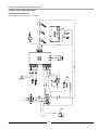
8.2 Matrix Factory Wiring Schematic
8.2.1 Boiler Control Wiring
Consult diagram on unit for exact wire routing.
31
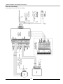
Matrix Installation and Operation Instructions
8.2.2 Fan Control Wiring
Consult diagram on unit for exact wire routing.
32
Matrix Installation and Operation Instructions
9.0 CONTROL SETUP
The Matrix used two devices to control the functions required by the Matrix. The Matrix Boiler Control (red face) controls and
ensures the safe operation of the boiler functions of the Matrix much the same as the Sentry 2100 does in the Trinity products. The
Matrix Fan Control (blue face) controls all of the operation and safety functions related to air handling and hot water dispatching.
The fan controller controls the forced air modulation, ventilation, as well as priority of domestic hot water and secondary heating
systems.
ATTENTION
The Matrix Boiler Control (Sentry) is different from the Sentry controller used on any other NTI
products and is NOT INTERCHANGEABLE.
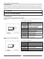
9.1 Controller Displays
9.1.1 Matrix Boiler Control (Sentry) Display (Red Face Plate)
The Matrix Boiler Control communicates to the user what is happening in the system by using an LED display and a series of LED
indicators.
Table 9.1 Matrix Boiler Control Display
Display
Burner/Brûleur
Forced Air
Demand
Burner/Bruleur
Forced Air Demand
Hydronic Demand
DHW Demand
Boiler
Temp
A
Boiler
Setpoint
C
Air
Temp
Hydronic Demand
DHW Demand
Gas Input
Value
T
Boiler Temp
Boiler Setpoint
Matrix Boiler Control
Air Temp
Gas Input Value
Description
Indicates that the ignition system is
activated
Indicates a call for forced air heat –
Please note. There may still be a call
for forced air heat even when
thermostat is satisfied (off).
Indicates a call for hydronic heat
Indicates a call for domestic hot water
When illuminated, display is showing
boiler water temperature
When illuminated, display is showing
boiler water set point
When illuminated, display is showing
outdoor temperature
When illuminated, display is showing
current gas input value. See chart to
determine input rate.
9.1.2 Matrix Fan Control Display (Blue Face
Plate)
Table 9.2 Matrix Fan Control Display
Display
Space Heat
Cooling
DHW
Hydronic
Space Heat
Cooling
DHW
Hydronic
Recirc. HRV On Defrost
NC
COM
NO
ReCirc.
High
Humidity
HRV On
Defrost
High Humidity
Matrix Fan Control
33
Description
Indicates a call for forced air heating
Indicates a call for cooling
Indicates a call for domestic hot water
Indicates a call for hydronic heat
Indicates a call for continuous
circulation/ventilation
Indicates the HRV is ventilating
Indicates the HRV is in defrost mode
Indicates a call for high ventilation of HRV
Matrix Installation and Operation Instructions
9.2 Operation and Set-up
The Matrix employs a pneumatic modulation system. This modulation system increases or decreases the velocity of the combustion
blower, to meet the demand for heating. The gas valve senses this change in blower pressure and introduces the required amount of
gas to ensure correct combustion. The Sentry reads the boiler water temperature, compares it to the set point, and adjusts the burner
firing rate accordingly by varying the speed of the combustion blower.
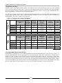
The (Blue) Fan Controller communicates the appropriate demand and temperature set point to the (Red) Boiler Controller via a
series of digital and analog inputs. Table 9.3 shows the Boiler Controller’s response to the demand. For more information on
‘RESET MODE’ see section ‘9.3 Outdoor Sensor Operation’.
RESET
MODE
CONVENTIONAL
MODE
Table 9.3 Conventional vs. Outdoor Reset Mode
Standby/Storage
Mode
Primary
Forced Air
Call (W1)
Auxiliary
Forced Air
Call (W2)
Shared Call
Forced
Air/Hydronic
Condition
Storage
Off
Storage
On
Heat (W1)
Aux Heat
(W2)
Set Point
-
160°F
SP
Burner On
-
140°F
SP
Burner Off
Heat Circ.
Off
180°F
On
210°F
On
210°F
On
Shared (W1/W2
and H)
Greater of SP/ HI
and HYD
Greater of SP/HI
and HYD
210°F
On
Standby/Storage
Mode
Primary
Forced Air
Call (W1)
Auxiliary
Forced Air
Call (W2)
Shared Call
Forced
Air/Hydronic
Condition
Storage
Off
Storage
On
Heat (W1)
Aux Heat
(W2)
Set Point
-
160°F
SP
Burner On
-
140°F
SP
Burner Off
Heat Circ.
Off
180°F
On
Shared (W1/W2
and H)
Greater of SP/ HI
Calc. and HYDCalc.
Greater of SP/ HI
Calc. and HYDCalc.
210°F
On
Note 1
HINote 1
Note 1
HINote 1
Note 1
HI Calc. Note 1
Note 1
HI Calc. Note 1
210°F
On
210°F
On
Hydronic
Demand (H)
Hydronic Call
HYD
DHW
Demand
Domestic
Only
H2O to
H2O+30
HYD-DIF
H2O+30
HYD + 10
On
210°F
On
Hydronic
Demand (H)
DHW
Demand
Hydronic Call
HYDCalc.
Domestic
Only
H2O to
H2O+30
HYDCalc.-DIF
H2O+30
HYDCalc.+ 10
On
210°F
On
Note 1. SP (Setpoint) received from Matrix Fan Controller.
9.2.1 Setting Matrix Boiler Control (Sentry)
Programming is accomplished by a series of three push buttons located on the bottom side of the control. (Function, ↑ and ↓). To
enter the programming mode, press the function key once. To scroll through the various menu options depress ↑ until the menu is
displayed. To alter the value press Function once, and the current value will be displayed, then use ↑ for up, and ↓ for down, until
the desired value is obtained. To enter the selected value press Function, which will return to the menu. When all desired values are
selected, scroll to the RUN menu, and press Function, which exits the Programming Mode and initiates normal operation. A safety
feature has been added to ensure that if the control is left in the Program Mode, the unit will turn off if left in program mode longer
than 30 seconds without receiving an input. Press Function once to continue programming or to start boiler operation.
34
Matrix Installation and Operation Instructions
Table 9.4 Matrix Boiler Control Programming
Menu Level
Main
Value
Description
Typical Settings
Program Mode - When Run is displayed controller
is in ‘Prog’ mode. Arrow up or down to scroll
through menus
RUN
HYD
80-200
HI
80-200
DIF
1-40
RES
70-HI
SFS
HFS
LFS
75-100
100-240
46-100
FrE
ON/OFF
Sto
OFF-24
100-120 Infloor (High Mass)
140-160 Infloor (Low Mass)
140-160 Fan Coil
Hydronic Call Setpoint
Auxiliary Heat Setpoint – prior to outdoor reset
adjustment
Differential Setting - Applies only to Hydronic Only
setpoint. Temperature difference below setpoint at
which burner will re-light.
Sets Outdoor Reset Curve Slope – See
Determining Reset Temperature for more
information.
Starting Gas Input Value
Maximum Gas Input Value
Minimum Gas Input Value
Freeze Protection – Operates burner and circulator
if temperature drops below 40ºF.
Storage Feature Timer – Length of time in hours
storage feature will keep boiler hot.
190
10
85
80
240
48 (min 46)
ON
2
To start the control operation, you must return to RUN on the menu, and press Function. Normal
operation will begin. Controller will return to RUN mode if no button is pressed for 2 minutes.
9.2.2 Setting Matrix Fan Control
Just as the Matrix Boiler Controller controls all of the operation and safety functions of the boiler, the Matrix Fan Controller,
controls all of the operation and safety functions related to air handling and hot water dispatching. The fan controller controls the
forced air modulation, ventilation, as well as priority of domestic hot water and secondary heating
systems.
Table 9.5 Matrix Fan Control Programming
Main
Sub
Menu Level
Value
Description
Default
RUN
OFF
HRV
ON
H2O
PF1
PF2
PF3
40-Y2
Y1-160
40-160
30-100
30-100
30-100
30-100
30-100
30-100
30-100
30-100
100-160
rAd
1 or 2
HEA
Y1
Y2
FAN
BAL
SCL
ECL
SCH
ECH
SOL
EOL
SOH
EOH
ON
PF1
80
120
40
60
60
60
60
100
100
100
100
125
2
When Run is displayed, controller is in ‘Prog’ mode. Arrow up or down to scroll
through menus
HRV Mode – Always off unless call for high ventilation (DH)
HRV Mode – Continuous Ventilation. HRV will exchange air at low ventilation
rate during a call for forced air heat (W1 or W2) or continuous circulation (G).
Will increase to high ventilation rate with a high ventilation call (24vac @ DH)
Heat Profile 1 400 to 1000CFM; 50,000 Btu/h max.
Heat Profile 2 400 to 1100CFM; 77,000 Btu/h max.
Heat Profile 3 400 to 1200CFM; 105,000 Btu/h max.
Stage 1 AC/HP Flow x 10 = CFM, settable from 400 up to Y2 (1600 max).
Stage 2 AC/HP Flow x 10 = CFM, settable from Y1 (400 min) up to 1600.
Fan circulation rate (G) x 10 = CFM, settable from 400 to 1600.
HRV Balancing – (see HRV section for more details)
Set point for desired DHW temperature in degrees Fahrenheit.
Determines the anticipated supply plenum size. For units with the 20x16” Supply
Plenum, set to 1. For units with the 22.5x18.5” Supply Plenum, set to 2.
To start the control operation, you must return to RUN on the menu, and press Function. Normal
operation will begin. Controller will return to RUN mode if no button is pressed for 2 minutes.
35
Matrix Installation and Operation Instructions
9.3 Outdoor Sensor Operation
The outdoor sensor is connected to the terminal board on the left side of the matrix. The two terminals are labeled ‘OUTDOOR
SENSOR’.
When the Outdoor sensor is not used, or the outdoor temperature is below 0°F, the Matrix operates at a boiler water temperature
equal to the HYD or HI setpoint during a call for Hydronic or Emergency Heat respectively. When the sensor is used and the
outdoor temperature is above 0°F, the Matrix boiler control automatically reduces the operating temperature of the boiler during
those calls. Using the following formula, the control factors in the current outdoor temperature, control setpoint (HYD or HI), and
the RES (reset) setpoint, in determining the appropriate operating water temperature.
Figure 9.2 Outdoor Reset Calculation
Formula:
Operating Temperature = {(RES – Outdoor Temp) x (HYD – RES) / RES} + RES
Note: Substitute HYD for HI during a call for Emergency Heat.
Example:
•
There is a call for Hydronic heat; therefore the control uses the HYD programmed
setting.
•
The HYD is programmed to be 160°F.
•
The RES is programmed to be 85°F.
•
The outdoor temperature is 40°F.
Operating Temperature = {(85 – 40) x (160 – 85) / 85} + 85 = 125°F
The following chart illustrates the effect of changing outdoor temperature on the boiler operating
temperature for the above example.
Reset Curve for Res=85 & Setpoint=160
170
Water Temp. (F)
150
130
110
90
70
-10
0
10
20
30
40
50
60
Outdoor Temperature (deg.F)
36
70
80
90
100
Matrix Installation and Operation Instructions
10.0 MATRIX BLOWER OPERATION
10.1 Forced Air Heating
The Matrix forced-air heating module is a step-modulated system, which provides varying heat output rates by adjusting air flow
and water temperature through a fan coil.
Table 10.1 Fancoil Output Chart
2
550
110
3
670
113
4
720
117
5
760
120
6
810
124
7
860
127
8
900
130
9
950
133
10
1000
136
104
105
108
110
112
114
115
117
118
19000
24000
27700
31400
35100
38800
42500
46300
50000
550
110
670
113
730
122
790
131
850
138
910
145
970
152
1030
158
1100
164
104
105
112
118
122
127
131
134
137
19000
24000
31500
39100
46700
54200
61800
69400
77000
550
670
750
820
900
975
1050
1120
1200
110
113
128
141
152
163
172
181
190
104
105
116
125
132
139
144
149
153
19000
24000
35500
47100
58700
70200
81800
93400
105000
Actual Output rates may vary from
what is shown
Heat Profile 1 (PF1)
Heat Profile 2 (PF2)
Heat Profile 3 (PF3)
Heating
Set Point Air Temp
Set Point Air Temp
Set Point Air Temp
CFM
Btu/Hr Out CFM
Btu/Hr Out CFM
Btu/Hr Out
Stage
(°F)
(°F)
(°F)
(°F)
(°F)
(°F)
1
400
108
400
108
104
14000
104
14000 400
108
104
14000
Example. At stage 4 (Profile 1) the Matrix provides 720 CFM across the fan coil, which is receiving 117°F water from the boiler. The
coil then supplies plenum air at 108° F or ~27700 BTU/hr.
On an initial thermostat call (24VAC @ W1), space heating begins by providing heat at Stage 3 (~24,000 BTU/hr) (if hydronic heat
is also calling (24VAC @ H) heating will begin at stage 1) and so long as the thermostat is not satisfied, incrementally increases to
a maximum of Stage 10 (maximum output). When the thermostat becomes satisfied, an average of the heat output rate during the
call is calculated. The boiler remains lit and the space heat output begins an incremental decrease in heat output rate beginning with
the stage just below the calculated average and ending with either the thermostat re-calling or if the thermostat never re-calls, the
output rate decreases to minimum stage after which the boiler shuts off.
If the thermostat re-calls prior to the minimum heat stage, a new calculated average of the thermostat off cycle is calculated and the
boiler again begins an increasing ramp, only this time it begins at the calculated stage and not necessarily at the minimum stage.
This computation “hunts” for the heat loss of the dwelling based on the reaction of the thermostat to the rise and fall of the space
temperature and the heat cycle rate of the thermostat.
If at any time the plenum temperature exceeds 160°F, the boiler will stop supplying heat until the temperature in the supply plenum
drops below 140ºF, during which time an AL2 error message will be displayed.
ATTENTION
The burner will remain on and the Matrix will provide heat when the thermostat is off. This is normal and is
required to provide constant efficient heat.
37
Matrix Installation and Operation Instructions
Call for Heat (24VAC @ W1): Normal Thermostat call, Matrix operates as a step-modulating furnace as described above. If
HRV set to ‘ON’, HRV will operate at the low (continuous) ventilation rate.
Call for Auxiliary Heat (24 VAC @ W2): When calling, furnace will provide heat at a stage 10 output rate. With a call for
auxiliary heating the Matrix will function as a single stage, full fire appliance. This means the burner will come on with a
thermostat call and go off when the call is satisfied. If HRV set to ‘ON’, HRV will operate at the low (continuous) ventilation rate.
Outdoor Sensor: The auxiliary heating function (24VAC @ W2) will utilize the outdoor sensor if available. The outdoor reset
function is not used for W1 heating. This function is also active during a hydronic heat demand (24VAC @ H).
Plenum Sensor: The Matrix is equipped with a plenum temperature sensor that must be field installed in the supply plenum and
wired to the furnaces external terminal strip. When installed the Matrix fan control displays the plenum temperature and will use it
to detect problems in the supply of heat to the space.
Call for Circulating Fan (24VAC @ G): Matrix operates at the programmed air circulation rate according to the “FAN” setting
in the Fan (blue) controller (400-1600 CFM). If HRV is set to ‘ON’ (See 8.2 Fan Controller), the HRV will ventilate at the low
(Continuous) ventilation rate.
Call for Dehumidification (24VAC @ DH): Matrix operates at the minimum air circulation rate (400 CFM). HRV will
ventilate at the high (Override) ventilation rate.
Call for Cooling Fan (24VAC @ Y1): Matrix operates at the prescribed air circulation rate (Y1x10 CFM – See 8.2 Fan
Control). HRV will not operate during a call for cooling unless there is a concurrent call for DH – Dehumidification or G –
Continuous and HRV is set to ON.
Call for Cooling Fan (24VAC @ Y2): Matrix operates at the prescribed air circulation rate (Y2x10 CFM – See 8.2 Fan
Control). HRV will not operate during a call for cooling unless there is a concurrent call for DH – Dehumidification or G –
Continuous and HRV is set to ON.
10.2 Duct Sizing
When sizing ductwork, a maximum flow velocity of 800 fpm is
desired. Table 11 shows common duct sizes at specified flows. The
maximum flows that can be expected are shown in Table 10.3. It is
important to maintain the return plenum pressure as low as possible.
Keeping this ductwork as free flowing as possible will offer more
supply static pressure to overcome A/C coils, closed registers etc while
maintaining constant flow.
Any additional filtration, humidification, or de-humidification
equipment should be installed external to the return or supply ducts so
not to create additional restriction.
Table 10.2 Duct Size vs. Air Flow
Airflow
(CFM)
Area
(sqft)
Duct Sizing
(inches)
1600
2
24x12
1200
1.5
24x10
1000
1.25
800
1
Table 10.3 Maximum Air Flow Rates
Fan Control Setting
Heating
Cooling
(HEA)
(COO)
160 max
ESPmax*
CFM
.35 inwg
1600
160 max
.6 inwg
1500
160 max
.75 inwg
1400
120 (3 Ton)
1200
80 (2 Ton)
800
PF3
No Cooling
<1 inwg
1200
PF2
No Cooling
<1 inwg
1100
PF1
No Cooling
<1 inwg
1000
Example #1 No cooling function with Heating
profile of PF2 selected. Maximum airflow will be
1100 CFM.
20x16
20x12
18x12
20x10
18x10
16x12
18x8
16x10
12x12
Example #2 Cooling set to 800 CFM for 2 tons of
cooling with Heating profile of PF3 selected.
Maximum airflow will be greater of cooling or heating
function. Maximum 1200 CFM.
Based on 800 fpm max airflow velocity
*Measured from return plenum to supply plenum prior to A/C coil.
ECM motor can produce near constant flow provided horsepower or
maximum speed of motor is not exceeded.
38
Matrix Installation and Operation Instructions
11.0 HEAT RECOVERY VENTILATION
11.1 Ventilation Needs
With the evolution toward more energy efficient, tighter homes, air quality problems have increased. With less natural ventilation
pollutants such as pet dander, humidity, tobacco smoke and wood ash now become trapped inside the home. Mechanical
ventilation is the process of exhausting the polluted air from the space and replacing it with fresh air from outside. The amount of
ventilation required varies from home to home and can be estimated using one of the following methods:
11.1.1 Room Count Calculation
Number of
Living Space
Rooms
Master Bedroom
With Basement
Without
Basement
Single Bedroom
Living Room
Dining Room
Family Room
Recreational
Room
Other
Kitchen
Bathroom
Laundry Room
Utility Room
CFM (L/S)
CFM Req'd
x 20 cfm (10 L/s)
x 20 cfm (10 L/s)
=
=
x 10 cfm (5 L/s)
x 10 cfm (5 L/s)
x 10 cfm (5 L/s)
x 10 cfm (5 L/s)
=
=
=
=
x 10 cfm (5 L/s)
=
x 10 cfm (5 L/s)
x 10 cfm (5 L/s)
x 10 cfm (5 L/s)
x 10 cfm (5 L/s)
=
=
=
=
Total Ventilation Requirement (sum last column)
=
11.1.2 Air Change per Hour Method
Total cu.ft x 0.3 / 60 = Total Ventilation Required
Example.
A 25’ x 40’ house with basement
1000 sqft x 8’ high x 2(main floor and basement) = 16,000 cu.ft
16,000 x .3 air changes per hour = 4,800 cu.ft/hr
4,800 cu.ft/hr / 60 = 80 cfm
80 cfm is ventilation requirement
39
Matrix Installation and Operation Instructions
11.2 Types of Installation
There are two basic methods of installing the ventilator in the Matrix:
Exhaust at the source. Stale air is drawn from the kitchen and bathrooms.
External Ducting to be 6”
insulated with Vapor Barrier
Warm Air
Supply
6’-0” min
Cold Air
Return
18” min
Stale Air From
Kitchen and
Bathroom
Exhaust from the return (Simplified System). Stale air is drawn from the return plenum.
External Ducting to be 6”
insulated with Vapor Barrier
Warm Air
Supply
6’-0” min
Cold Air
Return
18” min
Stale Air From
Cold Air Return
(Connection to be 4ft from
where return plenum attaches
to Matrix)
40
Matrix Installation and Operation Instructions
IMPORTANT
When using the Simplified System method, exhaust connection to the return must be 4’ from where the
return connects to the Matrix.
IMPORTANT
All main HRV ductwork to be 6” round.
Exterior connections are to be insulated and include a vapor barrier.
11.3 Damper Box
Included in the installation kit is a damper box. This
damper box eliminates the infiltration of cold outside
air when the HRV is off or in defrost mode. It is to
be installed with the actuator on the top side and
screw to the Matrix using the four screws provided.
Damper Box with Collar Installed
11.4 Condensate Drain
Condensation from defrost will collect in the
ventilator and drain from the sloped drain pan.
This condensation must be evacuated from the
unit. The condensate tubing provided must be
routed through the hole in the side of the
appliance and attached to the 90° elbow directly
underneath the ventilation module. From there
the condensate tube must be emptied into a
suitable floor drain or if necessary the emptying
drain must have a trap to prevent the infiltration
of toxic gases.
This End to Appropriate
Drain or Condensate Pump
Attach End of Supplied Tubing to
41
Matrix Installation and Operation Instructions
11.5 HRV Balancing
The HRV must be balance properly in order to operate at maximum efficiency and avoid problems.
The balancing process ensures the volume of fresh air from outside is equal to the amount of stale air being expelled from the home
over all air handler conditions. A variation of 10% is acceptable with the greater volume being stale air drawn from the home.
The Matrix uses motor speed to balance airflows. This method of balancing provides quieter operation and reduced energy
consumption over the traditional balancing damper approach.
Flow is measured with the use of a Magnehelic (0-.25 inwg range) and an airflow grid, flow collar or “Flow Measuring Station”.
NTI offers an airflow grid, PN: 83554, that is designed to be installed in a 1” hole located in a 6” duct. It is important that the flow
grid be the same size as the ductwork, and be installed according to the manufacturers instructions. Typically a straight run of 18”
on either side of the flow grid is adequate to avoid false readings. It is helpful if a flow grid is installed in each of the supply and
exhaust ducts.
Procedure:
1. Attach the upflow port of the flow grid to the positive pressure port of the Magnehelic and the down flow port to the negative
port.
2. Zero the Magnehelic.
3. Begin by selecting the heating profile required in the Matrix Fan Controller ‘HEA’ menu. Refer to the heating section of the
manual for more explanation. The heating profile selected dictates the air handler blower speeds and is important to the proper
functioning of the HRV. Every time the heating profile is changed the HRV will require re-balancing.
4. Once the heating profile is selected, advance to the ‘BAL’ menu. By pressing the ‘FUNCTION’ button you will enter the
balancing mode of the HRV. Press the up arrow button and advance through the menus until you reach the ‘EOH’ menu item.
By pressing the ‘FUNCTION’ button you will enter the ‘EOH’ menu. A number will appear. You will notice the HRV start, if
it is not already running, and the main blower of the air handle will come up to speed. The number on the display represents
the speed of the HRV fan in percentage. In the case of ‘EOH’ the number shown represents the speed of the exhaust ‘E’ fan
during a call for high ventilation ‘O’ (override) while the air handler blower is running at the high ‘H’ heating speed. The
maximum speed setting is 100%, the minimum 30%. Adjust the speed up or down until the desired flow rate is achieved.
Table 11.1, on the following page, has been provided to help in explaining the different settings.
5. Complete the table adjusting each of the setting to the HRV Ventilation Rate provided. These rates are a guideline only and
can be adjusted to meet the specific application.
-Note- When adjusting the exhaust speeds, the supply fan will increase to full speed.
When the balancing is complete, the HRV will maintain balance at any ventilation rate during any air handler blower condition.
This is a unique feature of the Matrix and is essential in providing efficient and adequate ventilation in this integrated system.
ATTENTION
The HRV balance must be checked and if necessary rebalanced every time the Heating (HEA) setting is
changed, or if there is change to the system which would significantly change the static pressure at the
return plenum or the exterior ducts to the HRV.
42
Matrix Installation and Operation Instructions
Stale
Exhaust
Figure 11.1 Sample Balancing Setup
Fresh
Supply
6” Flow Measurement Station,
Averaging Pitot Tube, or
Pitot TransferTube
Magnehelic (0-.25 inwg)
or Digital Manometer
Table 11.1 HRV Balancing Table
Menu
Item
EOH
SOH
EOL
SOL
ECH
SCH
ECL
SCL
Description
HRV Exhaust at Override (high ventilation) rate, balanced during High air
circulation rate (800/1000/1200CFM).
HRV Supply at Override (high ventilation) rate, balanced during High air
circulation rate (800/1000/1200CFM).
HRV Exhaust at Override (high ventilation) rate, balanced during Low air
circulation rate (300/400/500CFM).
HRV Supply at Override (high ventilation) rate, balanced during Low air
circulation rate (300/400/500CFM).
HRV Exhaust at Continuous (low ventilation) rate, balanced during High air
circulation rate (800/1000/1200CFM).
HRV Supply at Continuous (low ventilation) rate, balanced during High air
circulation rate (800/1000/1200CFM).
HRV Exhaust at Continuous (low ventilation) rate, balanced during Low air
circulation rate (300/400/500CFM).
HRV Supply at Continuous (low ventilation) rate, balanced during Low air
circulation rate (300/400/500CFM).
43
Sample HRV
Ventilation
Rates
120cfm
(55 L/s)
120cfm
(55 L/s)
120cfm
(55 L/s)
120cfm
(55 L/s)
70cfm
(30 L/s)
70cfm
(30 L/s)
70cfm
(30 L/s)
70cfm
(30 L/s)
Installed
Ventilation
Rates
Installed
Fan
Speed
Matrix Installation and Operation Instructions
12.0 LIGHTING BOILER
Before Start-up refer to Mandatory Pre-commissioning Procedure for Plastic Venting in Section 3.0.
Failure to follow these instructions can result in explosions, injury or death.
Prior to turning the gas supply on and lighting the appliance, ensure all aspects of the installation are
complete and in conformance with the instructions provided in this manual, including the Vent/AirIntake, Condensate Drain, and System Water Piping. Failure to precisely follow these instructions will
cause a fire or explosion resulting in property damage, serious injury or death.
Do not store or use gasoline or other flammable vapors & liquids in the vicinity of this or any other appliance. Failure to follow
instructions could result in explosion causing property damage, serious injury or death.
If you do not follow these instructions exactly, a fire or explosion may result causing property damage,
serious injury or death.
Should overheating occur or the gas supply fail to shut off, turn off the manual gas control valve to the
appliance. Failure to follow instructions could result in explosion causing property damage, serious
injury or death.
FOR YOUR SAFETY, READ BEFORE OPERATING_
A) This appliance does not have a pilot. It is equipped with an ignition device which automatically lights the burner. Do not
try to light the burner by hand.
B) BEFORE OPERATING smell all around the appliance area for gas. Be sure to smell next to the floor because some gas is
heavier than air and will settle on the floor.
WHAT TO DO IF YOU SMELL GAS:
• Do not try to light any appliance.
• Do not touch any electric switch.
• Do not use any phone in your building.
• Immediately call your gas supplier from a neighbor's phone. Follow the gas supplier's instructions.
• If you cannot reach your gas supplier, call the fire department.
C) Use only your hand to push in or turn the gas control knob. Never use tools. If the knob will not push in or turn by hand,
don't try to repair it, call a qualified service technician. Force or attempted repair may result in a fire or explosion.
D) Do not use this appliance if any part has been under water. Immediately call a qualified service technician to inspect the
appliance and to replace any part of the control system and any gas control which has been under water.
OPERATING INSTRUCTIONS_
1. STOP! Read the safety information above very carefully.
2. Set the thermostat to lowest setting. Turn off all electric power to the appliance.
3. This appliance does not have a pilot. It is equipped with an ignition device which automatically lights the burner. Do not
try to light the burner by hand.
4. Turn the manual gas valve to the OFF position. Remove front access panel.
5. Wait five (5) minutes to clear out any gas. Then smell for gas, including near the floor. If you smell gas, STOP! Follow
“B” in the safety information above. If you don't smell gas, go to the next step.
6. Turn the manual gas valve ON. Wait an additional five (5) minutes smelling for gas.
7. Replace the front access panel.
8. Set thermostat to highest setting. Turn on all electric power to the appliance.
9. Ignition sequence is automatic. Combustion will occur after a brief fan purge.
10. If ignition does not occur, follow the instructions “To Turn Off Gas To Appliance” and call your service technician or gas
supplier.
TO TURN OFF GAS TO THE APPLIANCE_
1. STOP! Read the safety information above very carefully.
2.
3.
Turn off all electric power to the appliance
Turn the manual gas valve to the OFF position
44
Matrix Installation and Operation Instructions
The initial lighting of the appliance must be performed by a licensed Gas Technician. Failure to follow
instructions may result in property damage, serious injury or death.
•
•
•
Ensure the appliance is wired in accordance with this manual.
Ensure the gas shut-off valve is turned on, and that the gas system has been fully tested for leaks.
Ensure the system is completely filled with water, and that ALL the air is purged out.
Allow primers/cements to cure for 8 hours prior to Start-up. If curing time is less than 8 hours, first
perform Steps 2 through 6 of Mandatory Pre-commissioning Procedure for Plastic Venting in Section
3.0. Failure to follow these instructions can result in explosion, serious injury or death.
Initial Start-Up
1. Turn on power to the Trinity Lx and turn-up the Thermostat(s). The appliance should run through a purge, and combustion
should occur. (The control system has a built in ignition retry, allowing the system to try at least three times, before lockingout.)
2. With the unit operating at full capacity, verify that the gas line pressure is 4-10.5 inches w.c. for Natural gas, and 9-13 inches
w.c. for Propane (See Section 5.0 for details).
3. Using an appropriate Oxygen or Carbon Dioxide analyzer, take a sample of the flue gas. The sample must fall within the
acceptable ranges for Carbon Dioxide, which is 8.5% - 9.5% for Natural gas, and 9.5%-10.5% for propane (See Section 5.0
for details).
4. Perform at least three lights in succession to ensure proper operation.
5. After the three successive lights, unplug the flame probe, and allow the unit to cycle again. Ensure that it tries to light, and
locks out on safety reset. Once you have successfully activated the flame safety system, replace the wire on the flame sensor,
and reconfirm proper lighting.
If the unit fails to light consistently and smoothly, contact NTI for assistance at 1-800-688-2575. Never
allow the appliance to continue to operate if the ignition or operation of the burner is rough or erratic.
Failure to follow these instructions could result in serious injury or death.
Re-lighting Unit
1. Stop and read these instructions very carefully.
2. Set the thermostat to the lowest setting, and then turn off all power to the appliance.
3. This appliance does not have a pilot. It is equipped with an ignition device that automatically lights the burner. Do not try to
light the burner by hand.
4. Turn the gas shut-off valve to the off position, and then remove the front cover.
5. Wait five (5) minutes to clear out any gas. Then check for gas, including near the floor. If you smell gas “Stop” and follow
“B” above. If you don’t detect any gas proceed to the next step.
6. Turn the gas shut-off valve to the on position, wait an addition five (5) minutes and check for gas.
7. Replace the front cover.
8. Set the thermostat to the highest setting, and then turn on all power to the appliance.
9. Ignition sequence is automatic, combustion will occur after a brief fan purge. Ignition will retry 3 times.
10. If ignition does not occur, “Turn off the gas and electricity to the appliance” and contact a professional service technician, or
gas supplier.
Turning Off The Appliance
1. Set the thermostat to the lowest setting, and then turn off all power to the appliance.
2. Turn the gas shut-off valve to the off position.
45
Matrix Installation and Operation Instructions
13.0 TROUBLE SHOOTING
This section is intended to assist the service technician in detecting and correcting common errors. The Matrix Boiler and Fan
Controls are equipped with an internal diagnostic system that verifies control operation. The following series of error codes has
been developed to aid in diagnosing control problems:
Symptom
Detected Problem
Solution
1.
Boiler Control (Red Face)
ER1
“Water Temperature Excessive”
Sentry has sensed a water
temperature in excess of 250ºF at
the Water Sensor.
ER2
“Water Sensor Short Circuit”
Control has sensed a short circuit
in the Water Sensor circuit.
ER3
“Water Sensor Open Circuit”
Control has sensed an open circuit
in the Water Sensor circuit.
ER4
“24V Limit Error”
Control has sensed a lack of 24V
on the outlet of the burner relay
(B1). Lockout lasts for one hour
before automatically resetting.
ER6
“Flame Lock Out”
Control has sensed a lack of 24V
to the gas valve during operation
or a Fenwal ignition lockout.
ER9
Internal Controller Fault
ASO
Air Switch
Open
ASC
Air Switch
Closed
Controller
Locks-up
This is displayed when the boiler is
expecting the air switch to be
closed by a differential pressure
generated when the combustion
blower turns on. It can occur
momentarily during normal
operation. A problem is indicated
when ASO is displayed
continuously.
This is displayed when the boiler
has turned the blower off and is
expecting the air switch to be
open. It can occur momentarily
during normal operation. A
problem is indicated when ASC is
displayed continuously.
Excessive noise, current, or
voltage spikes in the 120V power
supply.
2.
3.
See ER1
1.
Check wiring to Water Sensor for open circuits or shorting to ground. (Note:
ER3 will be displayed if temperature sensed is less then 0°F.)
2.
Replace Water Sensor if the resistance is not in the correct range. (See
thermister resistance charts in Figures 13.1 and 13.2)
1. Reset power, if error goes away the problem is intermittent and was likely
caused by a tripped limit that has automatically reset, check for adequate
water pressure and flow rate. Allow the boiler to cycle and verify proper
operation including outlet water temperature and flue temperature. If
operation is unsuccessful and the error reoccurs:
2. Matrix boilers are equipped with a low water pressure switch on the boiler
return that requires a minimum of 10PSI to complete the 24VAC ignition
circuit. Ensure the field-installed pressure gauge is reading a minimum of
12PSI. Replace water pressure switch if plumbing and pressure is correct
and if it measures an open circuit.
3. Check for continuity through the 24VAC limit wiring and manifold and stack
limits, replace limits or wiring that are not a closed circuit.
There is a problem in the ignition sequence; it could be caused by a faulty igniter,
flame sensor, gas valve or improper line pressure or combustion. Check ignition
sequence to determine which component is not functioning. (Control will retry
ignition sequence 1 hour after ER6 code originally occurs or if control is reset)
Indicates that the Controller has lost communication with an internal processor,
contact NTI.
1.
2.
3.
4.
1.
2.
3.
Ensure the vinyl tubes, connected between the air switch and the ports on
the inlet pipe, are in the proper locations. Negative side of switch connects
to the port on the 1-1/2” PVC elbow.
Check for blockage on the intake and exhaust vents.
If fan is running the air switch may be faulty, ensure it is set at 0.2”wc.
If fan is not running, check 120V wiring to blower, if ok remove low voltage
harness from blower, if blower fails to start, replace blower, if blower does
start the problem may be with blower or Controller.
Does the combustion fan run continuously at full speed while the error is
displayed? If so check for 24V from transformer, also check transformer
fuse. If 24V is present check the low voltage wiring from Controller to
combustion blower, replace Controller or Blower.
Is the combustion fan off? If so check for water in the air switch and air
switch tubes, replace switch if necessary.
Check venting termination with required venting described in manual.
Contact NTI.
1.
2.
Display Goes
Blank
If the boiler is extremely hot check for adequate water pressure and
circulation, contact NTI for assistance.
If not hot, check for sources of grounding or shorting at the Water Sensor
electrical connections, check wiring from Sensor to Boiler (Red) Control.
Replace Water Sensor if the resistance is not in the correct range. (See
thermister resistance charts in Figures 13.1 and 13.2)
No power to control or control
failure
3.
Check for 120V between terminals L1 and L2.
If 120V exists turn power off and remove line voltage harness from Control.
Then check for resistance between L1 and L2 of control, if the circuit is open
(O.L) the internal fuse has blown. Check for shorts in wires leading to
circulator prior to replacing controller. (Note: If fuse is good the circuit will
read between 300 and 400 Ohms.)
If 120V not present, check wiring and for 120V at source.
46
Matrix Installation and Operation Instructions
Symptom
Detected Problem
AL1
Communication Error with HRV
AL2
Plenum Temperature Limit of
160ºF Exceeded
Solution
1.
2.
3.
1.
2.
3.
Fenwal
Fan Controller (Blue Face)
1.
AL5
“DHW Time-Out”
The Control has locked out DHW
due to the demand lasting longer
than 2.5 hours.
AL7
‘Boiler Control Error’
Fan controller has failed to receive
run status from Boiler Control.
AL8
(& Blower Off)
‘Furnace Blower Error’
Blower has failed to meet a
minimum speed.
AL8
(& Blower On)
‘Furnace Blower Error’
Control has failed to sense that the
blower has reached a minimum
speed.
F3.5 Flashing
Lack of 24 V at fan controller
Two Flashes
on Fenwal
The Fenwal controller thinks that
there is a flame prior to ignition.
Indicates Ignition Lockout.
2.
3.
1.
2.
1.
2.
3.
1.
2.
1.
Check wiring connections between HRV and Fan Controller.
Check door switch on HRV.
Cycle power to appliance; contact NTI.
If plenum is hot, check operation of blower fan; contact NTI.
If plenum is not hot, check plenum sensor and wiring for shorts or damage.
Remove plenum sensor, PSO should be displayed, if so replace plenum
sensor, if not inspect wiring from Terminal Strip to Fan Control. Replace Fan
Control if necessary.
Reset the AL5 error by resetting the power or cycling the DHW call. Check
for proper operation of the DHW call.
Matrix units are provided with an integrated DHW flow meter, if the control is
registering a flow rate when the water is turned off; disconnect the electrical
lead to the flow meter. If the indicated flow rate drops to 0, replace flow
meter, if not, replace fan controller.
Ensure nothing is connected to the FS terminal of the terminal strip (unless
using a DHW tank aqua-stat to trigger a demand – check operation of aquastat).
Check for error code on Boiler Control.
Check control wiring from Boiler Control to Fan Control (Pins 17 and 18 on
Fan Control – See wiring schematic in Section 8.2).
Check for 120V to blower; ensure door switches are making the circuit.
Check wiring from Pin 6 at Fan Control (white wire) to Pin 15 at blower
motor.
Check for 24VDC at blower Pin 15, if present replace blower, if not replace
Fan Control.
Check wiring from Pin 5 at Fan Control (black wire), to Pin 16 at blower
motor.
Check for 3-5VDC at blower Pin 16, if present replace blower, if not replace
Fan Control.
Check/Replace 2A fuse – blown fuse indicates 24V supply shorted to
ground, or excessive load.
If the combustion sequence is normal, and there is no flame prior to ignition, the
Fenwal control is defective, and must be replaced.
If the condensate drain gets blocked, the boiler will become flooded and terminate
operation as the flame rod becomes immersed. This will damage the flame probe.
To correct, free the drain blockage, and permanently prevent it from reoccurring.
Remove and dry off the probe. Reinstall the probe and try for ignition, if it fails to
stay lit, leave the fan run for up to three hours to dry out the insulation and probe.
Three
Flashes on
Fenwal
“Ignition Lockout”
1.
2.
3.
4.
5.
Reset Boiler so it will attempt to ignite.
Check for proper operation of ignition components. Make sure igniter glows
and gas valve opens.
Check for proper line pressure at gas valve when it opens.
If boiler lights check for flame signal between FC1 and FC2 on Fenwal
control (If lower then 1.2 DC µAmps see “Boiler will not stay lit”).
Check combustion properties.
47
Matrix Installation and Operation Instructions
Symptom
Detected Problem
Solution
1.
Boiler will
not stay lit.
Indicates lack of a flame signal. In
order to stay running the flame
signal must be at least 0.7 µAmps
2.
3.
1.
Boiler bangs
or hisses
Bangs or sounds like a kettle while
burner is running indicates
insufficient flow
2.
General
3.
1.
2.
Boiler Lights
rough or
pulsates
3.
Typically an imbalance in the Air to
gas ratio
4.
Fan appears
to be
creating a
noise in the
house
Slight vibration can cause noise in
the residence
(This is not a warranty issue)
Making a rubbing noise. ((This is
not a warranty issue))
1.
2.
3.
1.
2.
If the Burner light on the Burner (Red) Control is going out, go to “Burner
shutting off”.
Check condensate drain for blockage and check the inlet piping for ingested
snow or water (if the flame rod gets wet, it may need to be replaced). Check
for resistance from flame rod to ground, must be an open circuit (O.L), if not,
remove rod and bend it away from the burner slightly.
Check for proper polarity of line and neutral wiring to the boiler.
Ensure the plumbing is as shown in manual. Check to see if pumps are
operating properly and water pressure is above 15psi. This problem can
lead to boiler overheating!
Boiler may be plugging with scale or magnetite, clean with Fernox DS-40
Descaler and Cleanser (NTI PN: 83450).
If glycol is being used the concentration may be to high, recommend using a
concentration lower then 35%.
Ensure that the venting lengths are in compliance with Section 3.4
Ensure that the line pressure during operation does not drop more than 20%
from the static line pressure.
Momentarily remove the intake vent from the boiler during ignition, if unit
lights smoothly with intake vent disconnected reconnect and check for proper
combustion if unit maintains smooth operation after ignition. (See Section
5.2) Calibrate for proper combustion. If problem persists contact NY
Thermal.
Heat exchanger may be dirty, remove burner door and inspect, clean if
necessary.
Use flexible gas line to insolate the vibration noises between the gas valve
and the line.
Don’t hang gas lines from floor joists.
Use rubber insulators with gas line supports.
If gas valve is not held when the gas nipple is connected, the force of
tightening the fitting can damage the valve, and warp the fan housing.
If pipe is used, the gas line must not create any forces to the valve, either
vertically (weight of line), or horizontally (misaligned connection)
The following are the thermistor curves for diagnosing the water and outdoor air sensors:
Measure the resistance of the thermistor when disconnected.
Using the appropriate chart, find the resistance and move either vertical (water probe) or horizontal (air probe) until the line is
intersected.
Move 90 degrees to the corresponding temperature.
If the temperature is plus or minus 10 degrees, then the probe is operating correctly.
48
Matrix Installation and Operation Instructions
Figure 13.1 M atrix Thermistor Resistance Chart
1 Mohm Water Probe (Low Temp.)
Resistance (Mega Ohms)
2.25
2
1.75
1.5
1.25
1
0.75
0.5
0.25
0
50
60
70
80
90
100
110
120
130
140
Water Tem perature ( oF)
Figure 13.2 M atrix Thermistor Resistance Chart
1 Mohm Water Probe (Hi Temp.)
Resistance (Kilo Ohms)
120
100
80
60
40
20
0
160
170
180
190
200
210
220
230
o
Water Tem perature ( F)
Figure 13.3 Outdoor 10K probe
Resistance (Kilo Ohms)
100
80
60
40
20
0
100
75
50
Tem perature (F)
49
25
0
Matrix Installation and Operation Instructions
14.0 SEQUENCE OF OPERATION
Figure 14.1 Matrix Boiler Control Sequence Of Operation
120v Power
Applied
Displays version
b1.0
Furnace Control
closes T-C circuit.
Boiler in
standby mode
Awaiting Input
From Furnace Control
at Contacts A-C-T
Furnace Control
closes A-C circuit.
Furnace Control closes
A-C and T-C circuit.
Forced Air Demand
DHW Demand
Hydronic Demand
Energizes Internal
Circulator (C1)
Closed
Error
ASC
Sentry 2100
N/O
Open
`
Sentry 2100
VDC Signal
to Combustion
Blower
Sentry 2100
Combustion Blower
Starts, SFS (80)
Sentry 2100
Open
24 V
Water Temperature Limit
&
Flue Gas Temperature Limit
&
Water Pressure Limit
Closed
Check
Error
ASO
24 V
Power to Ignitor
120V to S1
Prepurge
Three
Retries
for Flame
Igniter warm-up
5 seconds
Checks Flame
Probe Signal
Power to Gas Valve
Sentry 2100
modulates combustion
blower based upon setpoint
and programing
Greater than 1.0 uAmp
Call for flame ends
50
Less than
0.6 uAmp
Matrix Installation and Operation Instructions
15.0 INSTALLATION CHECKLIST
Installation
1. If operating on Propane Gas, convert appliance using kit number 82650-1.
2. Install the Vent/Air-Intake piping in accordance with Sections 3.0 this manual. Ensure all joints are secured and cemented
properly. Both the Vent and Air-Intake pipes must terminate outdoors. Perform the Mandatory Pre-commissioning
Procedure for Plastic Venting in Section 3.1.
3. Connect the condensate drain in accordance with Section 4.0 of this manual.
4. Connect the gas supply in accordance with Section 5.0 of this manual.
5. Install the plumbing in accordance with the Sections 6.0 and 7.0 of this Manual. Flush/cleanse the internals of the heating
system (hydronic piping of hydronic systems only). Treat system water with Fernox F1 Protector.
6. Connect field wiring in accordance with Section 8.0 of this manual.
7. Advise home/building owner of their responsibilities with respect to maintaining the appliance.
The building owner is responsible for keeping the Vent/Air-Intake termination free of snow, ice, or other
potential blockages and for scheduling routine maintenance on the appliance (see Section 16.0). Failure
to properly maintain the appliance may result in serious injury or death.
Start-up
Allow primers/cements to cure for 8 hours prior to Start-up. If curing time is less than 8 hours, first
perform Steps 2 through 6 of Mandatory Pre-commissioning Procedure for Plastic Venting in Section
3.0. Failure to follow these instructions can result in explosion, serious injury or death.
1. Turn gas shut-off valve to the ON position.
2. Turn Power on to appliance.
3. Set Controller to the desired settings.
4. Turn thermostat up, Ignition will occur.
Operational Checklist
1. System is free of gas leaks.
2. System is free of water leaks.
3. Water pressure is maintained above 15 PSI.
4. All air is purged from the heating system piping.
5. Ensure proper water flow rate; unit must not kettle, bang, hiss or flash the water to steam.
6. Ensure gas line pressure is in accordance with Section 5.0.
7. System is free of combustion leaks.
8. Unit must operate smoothly.
9. Ensure the flue gas combustion readings are within the tolerances listed in Table 5.1.
10. Each ignition must be smooth.
11.Verify that all condensate lines are clean and drain freely.
Before Leaving
1. Remove line pressure gauge from gas valve, tighten bleed screw, test screw for leaks. See Section 11.0.
2. Install plug into the flue gas test port and test for leaks.
3. Allow the appliance to complete at least one heating cycle, or to operate for at least 15 minutes.
4. Always verify proper operation after servicing.
Instructions to Installing Contractor
1. Ensure that the customer receives the Warranty Documentation included with the installation manual.
2. Leave the manual with the customer so they know when to call for annual maintenance and inspection.
This appliance must have water flowing through it whenever the burner is firing. Failure to comply may
damage the unit, void the warranty, and cause serious injury or death.
Allowing the appliance to operate with a dirty combustion chamber will adversely affect its operation and
void the warranty. Failure to clean the heat exchanger on a frequency that matches the need of the
application may result in fire, property damage, or death.
51
Matrix Installation and Operation Instructions
16.0 ANNUAL MAINTENANCE AND INSPECTION
This unit must be inspected at the beginning of every heating season by a Qualified Technician.
Annual Inspection Checklist
1. Lighting is smooth and consistent, and the combustion fan is noise & vibration free.
2. The condensate freely flows from the unit, and is cleaned of sediment.
3. Relief Valve and air vents are not weeping.
4. Low water cut off is flushed (if applicable)
5. Examine all venting for evidence of leaks. Ensure vent screens are cleaned and clear of debris.
6. Check the burner plate for signs of leaking.
7. The combustion chamber must be inspected and cleaned.
8. Listen for water flow noises indicating a drop in appliance water flow rate.
Important - The hydronic system may need to be flushed to eliminate hard water scale
(Use Fernox DS-40 Descaler, NTI PN: 83450).
Boiler system cleansers and corrosion inhibitors must not be used to flush contaminants from water
heaters or potable water systems.
16.1 Combustion Chamber Cleaning Procedure
Units operating with LP Gas or in an industrial environment will have to be cleaned a minimum of once per year. Other
applications will require the combustion chamber to be cleaned after the first year of operation, with subsequent cleanings
scheduled based on the condition of the combustion chamber at the time. Unless a step is identified as model specific, the
following combustion chamber cleaning procedure is the same for all models.
1.
2.
3.
4.
5.
6.
7.
8.
9.
10.
13.
Crystalline Silica - Read carefully the warnings and handling instructions pertaining to Refractory
Ceramic Fibers before commencing any service work in the combustion chamber. Take all necessary
precautions and use recommended personal protective equipment as required.
Initiate a post-purge cycle to clear any gas from the combustion chamber, then turn gas valve off.
Access the combustion chamber by removing the aluminum burner door assembly of the appliance.
Remove the insulation disc (P/N 83112) located in the back of the combustion chamber to avoid damaging it during the
cleaning process. The disc is held in place with a 2.5mm "Allen-head" screw.
Use a vacuum with a high efficiency filter to remove any loose debris or dust.
Wet the inside of the combustion chamber with water. Use a garden hose with a trigger nozzle to direct pressurized water
through the gaps between the heat exchanger tubes. The water should pass in-between the heat exchanger tubes and exit
via the condensate drain. This process may require the use of some dry rags or plastic to protect electrical components
from being damaged by dripping or spraying water.
Use a nylon or other non-metallic brush to loosen the incrustations and any other contaminates that have remained stuck
on and in-between the tubes.
Repeat steps 5 and 6 until the heat exchanger is clean and water from the condensate drain runs clear.
Re-install the insulation disc (part no. 83112) to the back of the combustion chamber.
Inspect the insulation disc located on the back-side of the burner door (p/n 82769). Replace if damaged.
Re-install the burner door, gas-supply and Air-inlet pipe, check for gas leaks.
Perform the Operational Check List detailed in Section 13.0.
Replace any gaskets or insulation discs that show any signs of damage and do not re-use. Failure to
follow these instructions may result in fire, property damage or death.
52
Matrix Installation and Operation Instructions
Refractory Ceramic Fibers (RFC)
Personal Protective Equipment Recommended - Read the following warnings and handling
instructions carefully before commencing any service work in the combustion chamber. The insulating
material on the inside of the burner door and at the back of the combustion chamber contain Refractory
Ceramic Fibers and should not be handled without personal protective equipment.
Potential Carcinogen - Use of Refractory Ceramic Fibers in high temperature applications (above
1000oC) can result in the formation of Crystalline Silica (cristobalite), a respirable silica dust. Repeated
airborne exposure to crystalline silica dust may result in chronic lung infections, acute respiratory
illness, or death. Crystalline silica is listed as a (potential) occupational carcinogen by the following regulatory organizations:
International Agency for Research on Cancer (IARC), Canadian Centre for Occupational Health and Safety (CCOHS),
Occupational Safety and Health Administration (OSHA), and National Institute for Occupational Safety and Health (NIOSH).
Failure to comply with handling instructions in Table 14-1 may result in serious injury or death.
Crystalline Silica - Certain components confined in the combustion chamber may contain this potential
carcinogen. Improper installation, adjustment, alteration, service or maintenance can cause property
damage, serious injury (exposure to hazardous materials) or death. Refer to Table 14-1 for handling
instruction and recommended personal protective equipment. Installation and service must be performed by a qualified installer,
service agency or the gas supplier (who must read and follow the supplied instructions before installing, servicing, or removing
this appliance. This appliance contains materials that have been identified as carcinogenic, or possibly carcinogenic, to humans).
Table 16.1 Handling Instructions for Refractory Ceramic Fibers (RCF)
Reduce the Risk of Exposure
Precautions and Recommended Personal Protective Equipment
Avoid contact with skin and eyes • Wear long-sleeved clothing, gloves, and safety goggles or glasses.
Avoid breathing in silica dust
• Wear a respirator with a N95-rated filter efficiency or better. 1
• Use water to reduce airborne dust levels when cleaning the combustion chamber.
• Do not dry sweep silica dust. Pre-wet or use a vacuum with a high efficiency filter.
Avoid transferring contamination • When installing or removing RFCs, place the material in a sealable plastic bag.
• Remove contaminated clothing after use. Store in sealable container until cleaned.
• Wash contaminated clothing separately from other laundry.
First Aid Measures
If irritation persists after implementing first aid measures consult a physician.
• Skin - Wash with soap and water.
• Eyes - Do not rub eyes; flush with water immediately.
• Inhalation – Breathe in fresh air; drink water, sneeze or cough to clear irritated
passage ways.
Notes:
1
Respirator recommendations based on CCOHS and OSHA requirements at the time this document was written. Consult
your local regulatory authority regarding current requirements for respirators, personal protective equipment, handling,
and disposal of RCFs.
For more information on Refractory Ceramic Fibers, the risks, recommended handling procedures and acceptable disposal
practices contact the organization(s) listed below:
Canada (CCOHS): Telephone directory listing under
Government Blue Pages Canada—Health and Safety—
Canadian Centre for Occupational Health and Safety; or
website http://www.ccohs.ca.
United States (OSHA): Telephone directory listing under
United States Government—Department of Labor—
Occupational Safety and Health Administration; or website
http://www.osha.gov.
53
Matrix Installation and Operation Instructions
16.2 HRV/Air Handler Maintenance
WARNING
ALWAYS REMOVE POWER (120V) TO THE UNIT PRIOR TO SERVICING.
Once every three months. Replace furnace filter. May be required more frequently in beginning, especially if new construction.
The Matrix HRV module is relatively maintenance free but does require routine cleaning. Table 14 describes the necessary
maintenance.
Table 16.1 HRV Maintenance Items
Heat Recovery Core
Annually or as needed
Energy Recovery Core
Annually or as needed
Every 3 months or as needed
Annually or as needed
Filters
Inside Surfaces of Unit
Annually or as needed
54
Vacuum surfaces, let soak in warm water for three hours, spray
rinse and let dry
Vacuum surfaces
Vacuum Filters
Replace filters
Clean interior of unit (walls and drain pan) with a mild non-abrasive
soap. It is recommended to use products that are environmentally
friendly
Matrix Installation and Operation Instructions
17.0 PARTS LIST
Replacement parts are available from your stocking wholesaler. Homeowners must contact their local Installer or Wholesaler.
Installers or Wholesalers may contact NY Thermal Inc. for assistance at 506-657-6000.
No.
P.N.
Description
1
82657
Premix burner, 135.8
1A
82761
Premix Burner Gasket
2
83190
Transformer, 24V
3
83083
Matrix Fan Control
3A
83160
Matrix Boiler Control (Sentry 2100)
4
82052
Blower #RG130
5
82054
Gas Valve (CVI) VK8115F1134B
5A
82065
Gas Valve 1/2" npt elbow
5B
82600
Gas Valve Vent connection
6
82662
Air switch Huba @ .2"wc.
7
83035
Thermister, 1/4"NPT
8
82058
Ignition Module (Fenwal)
9
82708
IGNITER, #601, c/w SS shield
10
82762
Rauscchert Flame Rod
11
82763
Composit Flue Box
11A
82764
Composit Flue Box Gasket
11B
82765
Composit Flue Outlet Gasket
11C
83291-3
Flue Adapter Assembly (4.5")
12
82992
Manifold Limit, 1/4NPT
13
82596
Heat Exchanger (Canada)
13
83012
Heat Exchanger (US)
14
82650
LP orifice 5.20mm
15
82660
Stack Limit, 1/4BSP,190F, Dif=30
16
82766
Blower Outlet Gasket
17
82368
3/4" Water Connection Gasket
18
83042
Condensate Y Drain
18A
82913
Siphon Condensate Trap
19
82767
Cast aluminum Burner door
19A
82769
Ceramic burner door disc
19B
82770
Burner door gasket
20
82768
Igniter gasket
21
82228
Tempering valve #AM101-US-1
22
82771
Extended air tube
23
82011
Plate heat exchanger LA1430
24
83507
Flow Meter
25
82160
3 way Valve VU54S2016B, 3/4"
26
82973
3 way actuator VU844A1003B
27A
82754-1
PCB Optocoupler
28
82054-1
CVI Venturi 01
28A
82054-2
CVI Venturi Gasket
29
82622-3
Matrix Air Metering Assembly
30
81027-1
Outdoor Air Sensor
31
83223-1
Pressure Switch 1/4"NPT
32
83112
Divider Plate Insulation (c/w hardware)
33
83462
Tee, Brass, 1/4"
34
53035
Furnace Blower
35
83081
ECM Motor
36
82285
Expansion Tank
37
81396
Circ. Pump Grundfos UP15-42B7
38
83363
Fin Tube Coil 22.5" x 18"
39
83547
HRV Fan
40
83548
HRV HVC Board
41
83549
HRV Filter x 2
42
83550
HRV Core
43
83555
HRV Damper Actuator (24V)
44
83084
Matrix HRV Assembly
45
83222
Matrix Plenum Sensor
46
83208
Door Safety Switch
47
82539
Auto Air Vent, 1/8"
48
83551
6" Double Collar
49
83552
Keeper for 6" Collar
50
83553
HRV Door Switch
50
40
44
38
43
41
48
42
39
34
35
55
49