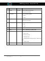
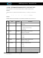
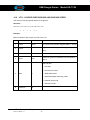
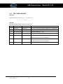
1
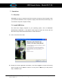
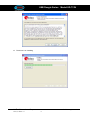
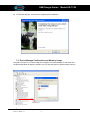
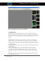
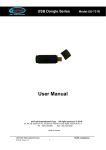
USB Dongle Series Model:UD-731N GPS USB Dongle Series Model:UD-731N UD-731N User’s Manual UniTraQ International Corp. All right reserved, © 2011 2F., No.136, Ziqiang S. Rd., Zhubei City, Hsinchu County 30264, Taiwan (R.O.C.) TEL:886-3-6578491 FAX:886-3-6578492 MADE IN TAIWAN UniTraQ International Corp. 2011,01, Version 1.1 RoHS compliance. 1 USB Dongle Series Model:UD-731N Contents 1. Introduction………………..………………………………………………………….………….3 2. Package contents……………………………………………………………………….……….3 3. System requirements…………………………………………………………………………...3 4. Features………………………..……………………………………………………………….…3 5. Specifications………………………………………………………………………………….…4 5.1 Electronic Characteristics…………………………………………………………………..4 5.2 Physical Characteristics…………………………………………………………………….5 6. Getting started…………………………………………………………………………………...6 6.1 LED Status……………………………………………………………………………….……6 7. Operations………………………………………………………………………………………..7 7.1 Overview……………………………………………………………………………………….7 7.2 Install USB Driver…………………………………………………………………………..7-9 7.3 Device Manage Confirmation and Memory Usage……………………………………..9 8. Application Software Introduction…………………………………………………………..10 8.1 u-Center……….……………………………………………………………………………...10 8.1.1 Features….……………………………………………………………………………...10 8.1.2 Starting u-center…………………………………………………………………….....11 8.1.3 Configuring the Serial Connection……………………………………………...11-12 8.1.4 Main Frame……………………………………………………………………….....12-13 9. Trouble Shooting………………………………………………………………………….…...14 10. Approved NMEA Message…………………………………………………………………….15 10.1 GGA–GLOBAL POSITIONING SYSTEM FIX DATA …..…………………………..15-16 10.2 GLL-LATITUDE AND LONGITUDE, WITH TIME OF POSITION FIX AND STATUS…………………………………………………………………………………..16-17 10.3 GSA - GPS DOP AND ACTIVE SATELLITES ……………………………………........18 10.4 GSV - GPS SATELLITE IN VIEW ………………………………………………………..19 10.5 RMC - RECOMMANDED MINIMUM SPECIFIC GPS/TRANSIT DATA ………….20-21 10.6 VTG - COURSE OVER GROUND AND GROUND SPEED …………………………..22 10.7 ZDA - TIME AND DATA….……………..………………………………………..………..23 UniTraQ International Corp. 2011,01, Version 1.1 RoHS compliance. 2 USB Dongle Series Model:UD-731N 1. Introduction The UD-731N is a USB Dongle with GPS receiver and built-in NAND FLASH memory together. Users can utilize it for navigation and memory storage application. Its 50 parallel channels and u-blox 5 chip which provide short start-up time and fast signal acquisition. Having fast time-to-first-fix and high sensitivity, the UD-731N offers good navigation performance even in urban canyons. The UD-731N is built in with NAND FLASH memory for users to utilize it for memory storage. The navigation software can also install in the built-in memory to support full navigation function with GPS receiver in the same device. It is compact and easily used with your laptop or mini notebook. 2. Package Contents UD-731N ………….. x 1 CD-ROM ……………x 1 USB cable……...……x 1 3. System Requirements The UD-731N requires the minimum to run on a laptop: Operating System: Windows 2000 / XP/Vista, Windows 7 CPU: 500 MHz, Pentium III System Memory: 128MB RAM Hard Disk: 50MB free space 4. Features 50 channel to acquire and track satellites simultaneously Built in NAND FLASH memory Industry-leading TTFF speed Signal detection better than -160 dBm SBAS (WAAS/EGNOS/MSAS) capable Cold start 29seconds Hot start < 1second USB Interface Accuracy 2.5m CEP Easy-plug-in Notebook RoHS compliance UniTraQ International Corp. 2011,01, Version 1.1 RoHS compliance. 3 USB Dongle Series Model:UD-731N 5. Specifications 5.1 Electronic Characteristics Parameter Specification Receiver Type 50 channels Re-acquisition sensitivity -160dBm Tracking sensitivity -160dBm Cold start sensitivity -145dBm Receiver frequency 1575.42MHz Code C/A code Accuracy (1) Position 2.5m CEP (2) Velocity 0.1m/sec Startup Time hot start < 1 sec warm start 29 sec cold start 29 sec Signal Reacquisition <1s Max navigation update rate 4Hz Operational Limits (1) Altitude 50000 m (2) velocity 500m/s Dynamics ≦4G (39.2m/sec2) Datum WGS-84 Protocol NMEA-0183 V2.3 Serial Interface USB interface Input Voltage 5V ±5% Power Consumption Tracking: 150 mA Connector USB B-type 4P male FLASH memory 2 or 4GB (optional) UniTraQ International Corp. 2011,01, Version 1.1 RoHS compliance. 4 USB Dongle Series Model:UD-731N 5.2 Physical Characteristics Parameter Specification Physical dimension 78.62mm X 24.83mm X 11.15mm Weight 22+-10%g UniTraQ International Corp. 2011,01, Version 1.1 RoHS compliance. 5 USB Dongle Series Model:UD-731N 6. Getting Started There are only few simple steps that you need to follow before using your UD-731N: Install the USB driver onto your laptop using the included CD-ROM . Plug the GPS receiver into your laptop’s USB port and assign the COM port. From within your mapping or navigation software (including the supplied GPS Application utility), you will need to manually configure the COM port that was assigned to the UD-731N GPS receiver by operation system so that proper communication between the GPS receiver and a mapping program can occur. Most software requires that you manually configure the COM port setting for any GPS device being used. 6.1 LED Status The LED flash status: RED LED : 1. Continue ON: GPS acquisition 2. 900ms on/ 100ms off : GPS tracking GREEN LED : Continue ON: while USB dongle plug into PC UniTraQ International Corp. 2011,01, Version 1.1 RoHS compliance. 6 USB Dongle Series Model:UD-731N 7. Operations 7.1 Overview UD-731N is an easy to use device with GPS receiver and memory built-in together. After you install the USB driver on the computer or laptop, both GPS receiver and maeory can work with the computer or laptop normally. 7.2 Install USB Driver The USB driver category depends on your operating system, such as WINDOWS Vista/XP/2000, WINDOWS 7, and WINCE. Please select the right one from the CD and then follow the procedures illustrated below to install USB driver. A. Click on the driver file to start. B. Review the license agreement information, and select I Agree to accept the licensing terms, and then click on Next to continue. You may click on Back to go to the previous step, or Cancel to quit. UniTraQ International Corp. 2011,01, Version 1.1 RoHS compliance. 7 USB Dongle Series Model:UD-731N C. The driver is on Installing UniTraQ International Corp. 2011,01, Version 1.1 RoHS compliance. 8 USB Dongle Series Model:UD-731N D. On the next dialogue, click Finish to complete driver installation 7.3 Device Manage Confirmation and Memory Usage: Plug UD-731N into PC, the GPS COM port will appear in Device Manage. At the same time the Removable Disk will appear, therefore you can click OK button to utilize storage memory. GPS COM port UniTraQ International Corp. 2011,01, Version 1.1 RoHS compliance. 9 USB Dongle Series Model:UD-731N 8. Application Software Introduction 8.1 u-Center The u-Center application software is provides by u-blox to support the devices with their GPS chipset built-in. This section describes the simple and quick user guides to this useful program. Please refer to the user manual of this software for more details. 8.1.1 Features u-center evaluation software provides system integrators and end users with a quick and simple way to interface with u-blox GPS chipsets, modules and boards. It enables easy evaluation, performance testing, development and debugging of GPS receivers. u-center allows easy connection to u-blox products and provides a suite of features to view, log, and analyze performance. The features include: Support for u-blox’ latest receivers using u-blox 5 positioning technology. u-center can communicate with these receivers using either the UBX protocol, or the NMEA-0183 standard protocol. Support for receivers that utilize standard NMEA strings. u-center presents all the information collected during the operation of the GPS receiver. All aspects of GPS data (position, velocity, time, satellite tracking, etc.) can be monitored and logged under various test scenarios for the evaluation of a receiver. u-center software allows analysis of the collected data in order to investigate performance issues such as accuracy, road test position and trajectory, satellite tracking, time to first fix, etc. All processed data can be captured in ASCII format and ported into popular spreadsheets for creating additional plots and statistics. Camera View: photographic data can be stored in the log file together with the navigation data and later be replayed in the application. Export data files to Google Earth and Google Maps. Supports AssistNow Online and AssistNow Offline. Data recording and playback function. Structural and graphical data visualization in realtime. Cut and paste export to standard PC application software. Docking views (real-time cockpit instruments): Satellite constellation, compass, clock, altimeter, speedometer, GPS and satellite information views. UniTraQ International Corp. 2011,01, Version 1.1 RoHS compliance. 10 USB Dongle Series Model:UD-731N 8.1.2 Starting u-center After a successful installation, u-center will start up as shown in Figure 1: Figure 1: Start Display 8.1.3 Configuring the Serial Connection When u-center is started for the first time, the COM port needs to be initialized. u-center supports the COM-Settings listed below and all u-blox GPS receivers are pre-configured this way. Parity: None Data Bits: 8 Stop Bits: 1 Flow Control: none Press the arrow in the Connect/Disconnect-Button and select the used COM-Port. As soon as u-center is synchronized to the GPS receiver, the Connect/Disconnect-Button on the Receiver Tool Bar changes the color to green and the display shows information about the satellite constellation, signal to noise ratio, time etc. UniTraQ International Corp. 2011,01, Version 1.1 RoHS compliance. 11 USB Dongle Series Model:UD-731N Figure 2: Start Display after a successful connection 8.1.4 Main Frame The Main Frame is the primary display screen of u-center. It displays all tool bars and some of the information provided by the GPS receiver. In the status bar, information about communication, UTC time, Operating Time, used protocol (NMEA or UBX), used file, etc. is shown. Button Function: A description about each button in the tool bars can be obtained by holding the mouse cursor over the button for a few seconds. A Tool Tip message will appear near the Icon with additional information while a detailed description is displayed in the Status Display. Status Display: display the current action or the function of a button if the mouse cursor is over the button u-blox 5 / Antaris Mode: u-center automatically detects the type of GPS receiver connected and activates the appropriate mode of operation in order to take optimal advantage of the features. The mode can also be manually selected through the menu bar. File in use: As soon as a file is used (this file must first be opened) the name of the file will be displayed (xxxxxx.ubx). UniTraQ International Corp. 2011,01, Version 1.1 RoHS compliance. 12 USB Dongle Series Model:UD-731N Protocol Information: This box indicates the current message set that is being used to communicate with the GPS receiver. This can be the NMEA-0183 standard or the UBX protocol. The UBX protocol provides more extensive information with the receiver. u-center can handle both protocols. Operating Time: The time elapsed since you started u-center UTC Time: The current time sent by the GPS receiver Communication Information: Shows the active COM port and baudrate. Color-Coding of this icon: Green: data is being received at the correct baudrate Dark Green: the last data received was valid, but there is no data to collect at this time. Red: data is being received but errors are detected Dark Red: no data is being received but errors have been detected in the past Gray: waiting for first data UniTraQ International Corp. 2011,01, Version 1.1 RoHS compliance. 13 USB Dongle Series Model:UD-731N 9. Trouble Shooting Satellite signal problem The following situations are normally if you find the GPS satellite signal is very low or absolute missing: There is something cover above. While you are in a tunnel. Inside of the building. Near by buildings. Put GPS receiver inside the car, some of the sun-control film with metal that makes microwave can not be radiate. GPS not fix problem If you see “GPS not fix” message on the screen after you enable the UD-731N GPS receiver, please consider the possible problems below: Wait few minutes. GPS position may cost several minutes. Make sure the UD-731N GPS receiver is put on a proper place. Some sun-control film for car may cutoff the satellite signal. You may replace it and try again. UniTraQ International Corp. 2011,01, Version 1.1 RoHS compliance. 14 USB Dongle Series Model:UD-731N 10. APPROVED NMEA MESSAGE The serial interface protocol is based on the National Marine Electronics Association’s NMEA 0183 ASCII interface specification. This standard is fully define in “NMEA 0183, Version 2.3” The standard may be obtained from NMEA, www.nmea.org 10.1 GGA – GLOBAL POSITIONING SYSTEM FIX DATA Time, position and fix related data for a GPS receiver. Structure: $GPGGA,hhmmss.sss,ddmm.mmmmm,a,dddmm.mmmmm,a,x,xx,x.x,x.x,M,x.x,M,x.x,xxxx*hh<CR><LF > 1 2 3 4 56 7 8 9 10 11 12 13 Example: $GPGGA,060932.448,2447.09599,N,12100.52049,E,1,08,1.1,108.7,M,,,,0000*0E<CR><LF> Field 1 Name UTC Time Example 060932.448 Description UTC of position in hhmmss.sss format, (000000.00 ~ 235959.99) 2 Latitude 2447.09599 Latitude in ddmm.mmmmm format ddmm.mmmmm Leading zeros transmitted 3 N/S Indicator N Latitude hemisphere indicator, ‘N’ = North, ‘S’ = South 4 Longitude 12100.52049 Longitude in dddmm.mmmmm format Leading zeros transmitted 5 E/W Indicator E Longitude hemisphere indicator, 'E' = East, 'W' = West 6 GPS quality 1 GPS quality indicator indicator 0: position fix unavailable 1: valid position fix, SPS mode 2: valid position fix, differential GPS mode 3: GPS PPS Mode, fix valid UniTraQ International Corp. 2011,01, Version 1.1 RoHS compliance. 15 USB Dongle Series Model:UD-731N 4: Real Time Kinematic. System used in RTK mode with fixed integers 5: Float RTK. Satellite system used in RTK mode. Floating integers 6: Estimated (dead reckoning) Mode 7: Manual Input Mode 8: Simulator Mode 7 Satellites Used 08 Number of satellites in use, (00 ~ 12) 8 HDOP 1.1 Horizontal dilution of precision, (00.0 ~ 99.9) 9 Altitude 108.7 mean sea level (geoid), (-9999.9 ~ 17999.9) 10 Geoid Separation Geoid separation in meters according to WGS-84 ellipsoid (-999.9 ~ 9999.9) 11 DGPS Age Age of DGPS data since last valid RTCM transmission in xxx format (seconds) NULL when DGPS not used 12 DGPS Station ID 0000 Differential reference station ID, 0000 ~ 1023 NULL when DGPS not used 13 Checksum 0E Note: The checksum field starts with a ‘*’ and consists of 2 characters representing a hex number. The checksum is the exclusive OR of all characters between ‘$’ and ‘*’. 10.2 GLL - LATITUDE AND LONGITUDE, WITH TIME OF POSITION FIX AND STATUS Latitude and longitude of current position, time, and status. Structure: $GPGLL,ddmm.mmmmm,a,dddmm.mmmmm,a,hhmmss.sss,A,a*hh<CR><LF> 1 2 3 4 5 6 7 8 Example: $GPGLL,4250.55899,S,14718.50849,E,092204.999,A,A*2D<CR><LF> UniTraQ International Corp. 2011,01, Version 1.1 RoHS compliance. 16 USB Dongle Series Field 1 Name Latitude Example 4250.55899 Model:UD-731N Description Latitude in ddmm.mmmmm format Leading zeros transmitted 2 N/S Indicator S Latitude hemisphere indicator ‘N’ = North ‘S’ = South 3 Longitude 14718.50849 Longitude in dddmm.mmmmm format Leading zeros transmitted 4 E/W Indicator E Longitude hemisphere indicator 'E' = East 'W' = West 5 UTC Time 092204.999 UTC time in hhmmss.sss format (000000.00 ~ 235959.99) 6 Status A Status, ‘A’ = Data valid, ‘V’ = Data not valid 7 Mode Indicator A Mode indicator ‘N’ = Data not valid ‘A’ = Autonomous mode ‘D’ = Differential mode ‘E’ = Estimated (dead reckoning) mode ‘M’ = Manual input mode ‘S’ = Simulator mode 8 Checksum 2D UniTraQ International Corp. 2011,01, Version 1.1 RoHS compliance. 17 USB Dongle Series 10.3 Model:UD-731N GSA - GPS DOP AND ACTIVE SATELLITES GPS receiver operating mode, satellites used in the navigation solution reported by the GGA or GNS sentence and DOP values. Structure: $GPGSA,A,x,xx,xx,xx,xx,xx,xx,xx,xx,xx,xx,xx,xx,x.x,x.x,x.x*hh<CR><LF> 1 2 3 3 3 3 3 3 3 3 3 3 3 3 4 5 6 7 Example: $GPGSA,A,3,01,20,19,13,,,,,,,,,40.4,24.4,32.2*0A<CR><LF> Field 1 Name Mode Example A Description Mode ‘M’ = Manual, forced to operate in 2D or 3D mode ‘A’ = Automatic, allowed to automatically switch 2D/3D 2 Mode 3 Fix type 1 = Fix not available 2 = 2D 3 = 3D 3 Satellite used 1~12 01,20,19,13,,,,, Satellite ID number, 01 to 32, of satellite used in solution, ,,,, up to 12 transmitted 4 PDOP 40.4 Position dilution of precision (00.0 to 99.9) 5 HDOP 24.4 Horizontal dilution of precision (00.0 to 99.9) 6 VDOP 32.2 Vertical dilution of precision (00.0 to 99.9) 7 Checksum 0A UniTraQ International Corp. 2011,01, Version 1.1 RoHS compliance. 18 USB Dongle Series 10.4 Model:UD-731N GSV - GPS SATELLITE IN VIEW Number of satellites in view, PRN number, elevation angle, azimuth angle, and C/No. Four satellites details are transmitted per message. Additional satellite in view information is send in subsequent GSV messages. Structure: $GPGSV,x,x,xx,xx,xx,xxx,xx,…,xx,xx,xxx,xx *hh<CR><LF> 1 2 3 4 5 6 7 4 5 6 7 8 Example: $GPGSV,3,1,09,28,81,225,41,24,66,323,44,20,48,066,43,17,45,336,41*78<CR><LF> $GPGSV,3,2,09,07,36,321,45,04,36,257,39,11,20,050,41,08,18,208,43*77<CR><LF Field Name Example Description 1 Number of message 3 Total number of GSV messages to be transmitted (1-3) 2 Sequence number 1 Sequence number of current GSV message 3 Satellites in view 09 Total number of satellites in view (00 ~ 12) 4 Satellite ID 28 Satellite ID number, GPS: 01 ~ 32, SBAS: 33 ~ 64 (33 = PRN120) 5 Elevation 81 Satellite elevation in degrees, (00 ~ 90) 6 Azimuth 225 Satellite azimuth angle in degrees, (000 ~ 359 ) 7 SNR 41 C/No in dB (00 ~ 99) Null when not tracking 8 Checksum 78 UniTraQ International Corp. 2011,01, Version 1.1 RoHS compliance. 19 USB Dongle Series Model:UD-731N 10.5 RMC - RECOMMANDED MINIMUM SPECIFIC GPS/TRANSIT DATA Time, date, position, course and speed data provided by a GNSS navigation receiver. Structure: $GPRMC,hhmmss.sss,A,dddmm.mmmmm,a,dddmm.mmmmm,a,x.x,x.x,ddmmyy,x.x,a,a*hh<CR><L F> 1 2 3 4 5 6 7 8 9 10 1112 13 Example: $GPRMC,092204.999,A,4250.55899,S,14718.50849,E,0.00,89.68,211200,,A*25<CR><LF> Field 1 Name UTC time Example 092204.999 Description UTC time in hhmmss.sss format (000000.00 ~ 235959.999) 2 Status A Status ‘V’ = Navigation receiver warning ‘A’ = Data Valid 3 Latitude 4250.55899 Latitude in dddmm.mmmmm format Leading zeros transmitted 4 N/S indicator S Latitude hemisphere indicator N/S ‘N’ = North ‘S’ = South 5 Longitude 14718.5084 Longitude in dddmm.mmmmm format Leading zeros transmitted 6 E/W Indicator E Longitude hemisphere indicator 'E' = East 'W' = West 7 Speed over ground 000.0 Speed over ground in knots (000.0 ~ 999.9) 8 Course over ground 000.0 Course over ground in degrees (000.0 ~ 359.9) 9 UTC Date UTC date of position fix, ddmmyy format 211200 UniTraQ International Corp. 2011,01, Version 1.1 RoHS compliance. 20 USB Dongle Series Model:UD-731N 10 Magnetic variation Magnetic variation in degrees (000.0 ~ 180.0) 11 Magnetic Variation Magnetic variation direction ‘E’ = East ‘W’ = West 12 Mode indicator A Mode indicator ‘N’ = Data not valid ‘A’ = Autonomous mode ‘D’ = Differential mode ‘E’ = Estimated (dead reckoning) mode ‘M’ = Manual input mode ‘S’ = Simulator mode 13 checksum 25 UniTraQ International Corp. 2011,01, Version 1.1 RoHS compliance. 21 USB Dongle Series 10.6 Model:UD-731N VTG - COURSE OVER GROUND AND GROUND SPEED The Actual course and speed relative to the ground. Structure: GPVTG,x.x,T,x.x,M,x.x,N,x.x,K,a*hh<CR><LF> 1 2 3 4 5 6 Example: $GPVTG,89.68,T,,M,0.00,N,0.0,K,A*5F<CR><LF> Field Name Example 1 Course 89.68 2 Course 3 Speed 0.00 4 Speed 0.00 Description True course over ground in degrees (000.0 ~ 359.9) Magnetic course over ground in degrees (000.0 ~ 359.9) Speed over ground in knots (000.0 ~ 999.9) Speed over ground in kilometers per hour (0000.0 ~ 1800.0) Mode indicator ‘N’ = not valid ‘A’ = Autonomous mode 5 Mode A ‘D’ = Differential mode ‘E’ = Estimated (dead reckoning) mode ‘M’ = Manual input mode ‘S’ = Simulator mode 6 Checksum 5F UniTraQ International Corp. 2011,01, Version 1.1 RoHS compliance. 22 USB Dongle Series 10.7 Model:UD-731N ZDA -TIME AND DATA Structure: $GPRMC,hhmmss.sss,dd,mm.yyyy, , ,xxx<CR><LF> 1 2 3 4 5 6 7 Example: $GPZDA,104548.04,25,03,2004,,*6C<CR><LF> Field Name Example Description 1 UTC time 104548.04 UTC time in hhmmss.ss format, 000000.00 ~ 235959.99 2 UTC time: day 25 UTC time: day (01 ... 31) 3 UTC time: month 03 UTC time: month (01 ... 12) 4 UTC time: year UTC time: year (4 digit year) 2004 5 Local zone hour Not being output by the receiver (NULL) 6 Local zone minutes Not being output by the receiver (NULL) 7 6C 6C Checksum UniTraQ International Corp. 2011,01, Version 1.1 RoHS compliance. 23 USB Dongle Series Model:UD-731N UniTraQ International Corp 2F., No.136, Ziqiang S. Rd., Zhubei City, Hsinchu County 30264, Taiwan (R.O.C.) TEL:886-3-6578491 Email Website FAX:886-3-6578492 [email protected] www.unitraq.com © 2011 UniTraQ International Corp. All rights reserved. Not to be reproduced in whole or part for any purpose without written permission of UniTraQ International Corp (“UniTraQ”) Information provided by UniTraQ is believed to be accurate and reliable. These materials are provided by UniTraQ as a service to its customers and may be used for informational purposes only. UniTraQ assumes no responsibility for errors or omissions in these materials, nor for its use. UniTraQ reserves the right to change specification at any time without notice. These materials are provides “as is” without warranty of any kind, either expressed or implied, relating to sale and/or use of UniTraQ products including liability or warranties relating to fitness for a particular purpose, consequential or incidental damages, merchantability, or infringement of any patent, copyright or other intellectual property right. UniTraQ further does not warrant the accuracy or completeness of the information, text, graphics or other items contained within these materials. UniTraQ shall not be liable for any special, indirect, incidental, or consequential damages, including without limitation, lost revenues or lost profits, which may result from the use of these materials. UniTraQ products are not intended for use in medical, life-support devices, or applications involving potential risk of death, personal injury, or severe property damage in case of failure of the product. UniTraQ International Corp. 2011,01, Version 1.1 RoHS compliance. 24