1
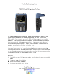
HI-204E
Mini-DIN
GPS Receiver
User Manual
HI-204E
WATERPROOF
GPS Receiver
1
General description of what
GPS is and how it works.
GPS (Global Positioning System) is the only system today
able to show you your exact position on the Earth anytime,
in any weather, anywhere. GPS satellites, 24 in all, orbit at
11,000
nautical
continuously
miles
monitored
above
by
the
ground
Earth.
They
stations
are
located
worldwide. The satellites transmit signals that can be
detected by anyone with a GPS receiver. Using the receiver,
you can determine your location with great precision.
The satellites are positioned so that we can receive signals
from six of them nearly 100 percent of the time at any point
on Earth. You need that many signals to get the best
position information. Satellites are equipped with very
precise clocks that keep accurate time to within three
nanoseconds- that's 0.000000003, or three billionths of a
second. This precision timing is important because the
receiver must determine exactly how long it take s for
signals to travel from each GPS satellite. The receiver uses
this information to calculate its position.
2
Although GPS was designed for military use, many
thousands of civi lians make use of it. The satellites actually
broadcast two signals, one is only formilitary use, and the
ther can be used by both military and civilians. Since GPS is
passive (you only need to receive the signal), there are no
restrictions on who can use the signal available to civilians.
GPS technology can be used in a variety of fields besides
providing navigation for vehicles on the sea, in the air and
on the ground. GPS applications also include keeping track
of where a fleet of trucks, trains, ships or planes are and
how fast they are moving; directin gemergency vehicles to
the scene of an accident; mapping where a city's assets are
located ; and providing precise timing for endeavors that
require large-scale coordination.
3
GLOBAL POSITIONING SYSTEM
HI-204E GPS RECEIVER
Pin Assignment
Connectors
1
3
5
2
4
6
1800±30mm
1
2
PS/2 Connector
Color
Function
CN1
Green
TX
5
White
4
RX
4
Red
VCC
2
Black
GND
1
1
Mini Din: 6 pin male
connector
2
Wire: 3.6 ± 0.1mm
Pocket PC
HI-204E PS/II GPS receiver Can Connecting to a female
PS/II Connector. One end from the female Connector is
+12V car charger (charging PDA and GPS receiver
simultaneously) the other end form the female PS/II
connector is the PDA connector for
connecting your PDA.
For notebook PC use:
HI-204E PS/II can also
connect with a PS/II to DB9
PS-232 serial cable or USB
connector.
5
1. HI-204E Series Introductions
HI-204E is a GPS receiver with PS/II mini-DIN interfaces
and built-in active antenna for high sensitivity to tracking
signal. HI-204E is well suited to system integration and
users who use any kinds of mobile devices, such as, PDA,
notebook PC, Tablet PC, etc. It satisfies a wide variety of
applications for car navigation, personal navigation or
touring devices, tracking and marine navigation purpose.
Users can simply plug it into a PDA or other type of
handheld PC running with suitable mapping and routing
software for navigation.
1.1 Standard Package
Before you start up, make sure that your package includes
the following items. If any items are missing or damaged,
contact your dealer immediately.
• HI-204E GPS Receiver unit
• Suction CUP
• User Manual CD (including
User Manual, HaiTest Testing
Program, Driver for PCMCIA card slot of Notebook PC)
6
Optional Accessories:
• PS/II to PDA connector and car charger
• PS/II to DB9 adapting cable
• PS/II to USB adapting cable
HI-204E-USB
HI-204E-XXXX
(Pocket PC Plug)
HI-204E-DB9
7
SECTION 1
INTRODUCTION
1.1 OVERVIEW
Fast Acquisition Enhanced Sensitivity
12 Channel GPS Sensor Module
The HI-204E is a compact all-in-one GPS module solution
intended
for
a
broad
range
of
Original
Equipment
Manufacturer (OEM) products, where fast and easy system
integration and minimal development risk is required.
The receiver continuously tracks all satellites in view and
provides accurate satellite positioning data. The HI-204E is
optimized for applications requiring good performance, low
cost, and maximum flexibility; suitable for a wide range of
OEM configurations including handhelds, sensors, asset
tracking, PDA-centric personal navigation system, and
vehicle navigation products.
Its 12 parallel channels and 4000 search bins provide fast
satellite signal acquisition and short startup time. Acquisition
sensitivity of -137dBm and tracking sensitivity of -145dBm
offers good navigation performance even in urban canyons
having limited sky view.
8
Satellite-based augmentation systems, such as WAAS and
EGNOS, are supported to yield improved accuracy.
Both the LVTTL-level and RS232-level serial interface are
provided on the interface connector. Supply voltage of 3.3V,
or 3.8V~12V are supported.
1.2 Features
• 12 parallel channel GPS receiver
• 4000 simultaneous time-frequency search bins
• SBAS (WAAS, EGNOS) support
• -137dBm acquisition sensitivity
• -145dBm tracking sensitivity
• < 10 second hot start
• < 45 second cold start
• 5m CEP accuracy
9
SECTION 2
RECEIVER OPERATION
Upon power up, after initial self-test has completed, the
HI-204E will begin satellite acquisition and tracking
process. Under normal open-sky condition, position-fix
can be achieved within approximately 35 seconds (within
10 seconds if valid ephemeris data is already collected
from
recent
use). After
receiver
position
has
been
calculated, valid position, velocity and time information are
transmitted through the on board serial interface.
The receiver uses the latest stored position, satellite data,
and current RTC time to achieve rapid GPS signal
acquisition and fast TTFF. If the receiver is transported over
a large distance across the globe, cold-start automaticlocate sequence is invoked. The first position fix may take
up to 50 sec searching the sky for the GPS signal. The
acquisition performance can be improved significantly if the
host initializes the receiver with a rough estimate of time
and user position.
10
As soon as GPS signal is acquired and tracked, the
HI-204E will transmit valid navigation infor mation
through
its
ser ial
interface. The
navigation
data
contains following information:
• Receiver position in latitude, longitude, and altitude
• Receiver velocity
• Time
• DOP error-magnification factor
• GPS signal tracking status
The HI-204E will perform 3D navigation when four or more
satellites are tracked. When three or fewer satellites are
tracked, altitude-hold is enabled using the last computed
altitude and 2D navigation mode is entered.
With signal blockage or rising and setting of the satellites,
where a change in satellite constellation used for position fix
occurred, large position error may result. The HI-204E
incorporates a proprietary algorithm to compensate the
effect of satellite constellation change, and maintains an
accurate smooth estimate of the receiver position, velocity,
and heading.
11
2.1 TECHNICAL SPECIFICATIONS
FEATURES
Receiver Type
Accuracy
DESCRIPTIONS
12 parallel channel, L1 C/A code
Position: 5m CEP
Velocity: 0.1m/sec
Startup Time
< 10sec hot start
< 45sec cold start
Reacquisition
Sensitivity
Update Rate
1s
-137dBm acquisition -145dBm tracking
1Hz
Dynamics
Operational Limits
4G (39.2m/sec2)
Altitude < 18,000m or velocity < 515m/s
(COCOM limit, either may be exceeded but
not both)
Serial Interface
Protocol
Input Voltage
LVTTL level and RS-232 level
NMEA-0183 V3.01
GPGGA, GPGLL, GPGSA, GPGSV,
GPRMC, GPVTG, GPZDA
4800 baud, 8, N, 1
Default WGS-84
User definable
Two 1.0mm pitch WTB S/R wafer
87213 SMT R/A type connector
3.3V DC +/-100mV 3.8V ~ 12.0V
Current Consumption
Dimension
Weight
Operating Temperature
90 ~ 110mA
43mm L x 42mm W x 13mm H
23g
-40°C ~ +85°C
Datum
Interface Connector
2.2 LED INDICATOR
LED flashing 0.25Hz
LED flashing 1Hz
12
Signal Searching
Position Fixed
< 35sec warm start
SECTION 3
HARDWARE INTERFACE
3.1 MECHANICAL DIMENSIONS
Unit:mm
Top View
69±0.2
I/O Cable
Build-in
patch antenna
Lateral View
20±0.2
I/O Cable
Bottom View
LED indicator
69±0.2
I/O Cable
CPU
Magnetic
73±0.2
13
Patch Antenna
pin-1
HI-204E Lateral View
3.2 PINOUT DESCRIPTION
Pin Number Signal Name
Description
Asynchronous serial
1
Serial Data Out 1 output at LVTTL level, to
output NMEA message
Asynchronous serial input
2
Serial Data In 1
at LVTTL level, to input
command message
Asynchronous serial
3
Serial Data Out 2 output at RS-232 level,
to output NMEA message
Asynchronous serial input
4
Serial Data In 2
at RS-232 level, to input
5
Power
3.8V ~ 12.0V DC input
6
Ground
Power and signal ground
command message
14
3.3 ONE-PULSE-PER-SECOND (1PPS) OUTPUT
The
one-pulse-per-second
output
is
provided
for
applications requiring precise timing measurements. The
output pulse is 1usec in duration. Rising edge of the output
pulse is accurate to +/-1usec with respect to the start of
each GPS second. Accuracy of the one-pulse-per-second
output is maintained only when the GPS receiver has valid
position fix.
The 1PPS output is always generated when the GPS
receiver is powered-on. Proper adjustment of the 1PPS
output to align with the GPS second requires calculation of
the receiver clock offset and clock drift-rate as part of the
position-velocity-time (PVT) solution. When enough satellite
signals are received to generate valid position fixes, the
1PPS output is adjusted to align with the GPS second in
several seconds. When the 1PPS output is brought in sync
with the GPS second, the 1PPS Valid Signal on the I/O pin
becomes active (HIGH); when the 1PPS output is not yet in
sync with the GPS second, the 1PPS Valid Signal remains
inactive (LOW).
15
As long as enough satellite signals are received to generate
valid position fixes, the 1PPS output remains synchronized
to the GPS second, and the 1PPS Valid Signal remains
active. If signal blockage prevents the receiver from
generating valid position fix, the 1PPS output will drift away
from the GPS second and the 1PPS Valid Signal will
become inactive. Upon re-acquiring enough satellites to
generate consecutive valid position fixes, the 1PPS Valid
Signal will become active again, signaling that the 1PPS
output is again synchronized with the GPS second.
For best stable operation of the 1PPS signal, it is to be
operated in static environment having clear view of the sky.
16
SECTION 4
SOFTWARE INTERFACE
This section describes the details of the serial port
commands through which the HI-204E is controlled and
monitored. The serial port commands allow users to set the
receiver parameters, configure output message type, and
retrieve status information. The baud rate and protocol of
the host COM port must match the baud rate and protocol
of the GPS receiver serial port for commands and data to
be successfully transmitted and received. The default
receiver protocol is 4800baud, 8 data bits, 1 stop bit, and
none parity.
4.1 NMEA OUTPUT MESSAGE SPECIFICATION
The HI-204E supports NMEA-0183 output format as
defined by the National Marine Electronics Association
(http://www.nmea.org). The currently supported NMEA
messages for GPS applications are:
GGA Global Positioning System Fix Data
GLL
Geographic Position Latitude / Longitude
GSA GNSS DOP and Active Satellites
GSV GNSS Satellites in View
RMC Recommended Minimum Specific GNSS Data
VTG
Course Over Ground and Ground Speed
17
4.1.1 NMEA Messages
The serial interface protocol is based on the National
Marine Electronics Association's NMEA 0183 ASCII
interface specification. This standard is fully define in
"NMEA 0183, Version 3.01" The standard may be obtained
from NMEA, www.nmea.org
4.1.2 GGA - GPS FIX DATA
Time, position and position-fix related data (number of
satellites in use, HDOP, etc.).
Format:
$GPGGA,<1>,<2>,<3>,<4>,<5>,<6>,<7>,<8>,<9>,
M,<10>,M,<11>,<12>,*<13><CR><LF>
Example:
$GPGGA,104549.04,2447.2038,N,12100.4990,E,1,06,
01.7,00078.8,M,0016.3,M,,*5C<CR><LF>
18
Field Example Description
1
104549.04 UTC time in hhmmss.ss format,
000000.00 ~ 235959.99
2
2447.2038 Latitude in ddmm.mmmm format
Leading zeros transmitted
3
N
Latitude hemisphere indicator,
'N' = North, 'S' = South
4
12100.4990 Longitude in dddmm.mmmm format
Leading zeros transmitted
5
E
Longitude hemisphere indicator,
'E' = East, 'W' = West
6
1
Position fix quality indicator
0: position fix unavailable
1: valid position fix, SPS mode
2: valid position fix, differential GPS mode
7
06
Number of satellites in use, 00 ~ 12
8
01.7
Horizontal dilution of precision, 00.0 ~ 99.9
9
00078.8 Antenna height above/below mean sea level,
-9999.9 ~ 17999.9
10
0016.3
Geoidal height, -999.9 ~ 9999.9
11
Age of DGPS data since last valid RTCM
transmission in xxx format (seconds)
NULL when DGPS not used
12
Differential reference station ID, 0000 ~ 1023
NULL when DGPS not used
13
5C
Checksum
Note: The checksum field starts with a '*' and consists of 2 characters
representing a hex number. The checksum is the exclusive
OR of all characters between '$' and '*'.
19
4.1.3 GLL - LATITUDE AND LONGITUDE, WITH TIME OF
POSITION FIX AND STATUS
Latitude and longitude of current position, time, and status.
Format:
$GPGLL,<1>,<2>,<3>,<4>,<5>,<6>,<7>*<8><CR><LF>
Example:
$GPGLL,2447.2073,N,12100.5022,E,104548.04,A,
A*65<CR><LF>
Field
1
Example
Description
2447.2073 Latitude in ddmm.mmmm format
Leading zeros transmitted
2
N
Latitude hemisphere indicator,
'N' = North, 'S' = South
3
12100.5022 Longitude in dddmm.mmmm format
Leading zeros transmitted
4
E
Longitude hemisphere indicator,
'E' = East, 'W' = West
5
104548.04 UTC time in hhmmss.ss format,
000000.00 ~ 235959.99
6
A
7
A
Status, 'A' = valid position,
'V' = navigation receiver warning
8
20
65
Mode indicator
'N' = Data invalid
'D' = Differential
'A' = Autonomous
'E' = Estimated
Checksum
4.1.4 GSA - GPS DOP AND
ACTIVE SATELLITES
GPS receiver operating mode, satellites used for navigation,
and DOP values.
Format:
$GPGSA,<1>,<2>,<3>,<3>,<3>,<3>,<3>,<3>,<3>,<3>,
<3>,<3>,<3>,<3>,<4>,<5>,<6>*<7><CR><LF>
Example:
$GPGSA,A,3,26,21,,,09,17,,,,,,,10.8,02.1,10.6*07<CR><LF>
Field
Example
1
A
Description
Mode, 'M' = Manual, 'A' = Automatic
2
3
Fix type, 1 = not available,
2 = 2D fix, 3 = 3D fix
3
26,21,,,09, PRN number, 01 to 32, of satellite
17,,,,,,
4
10.8
5
02.1
6
10.6
7
07
used in solution, up to 12 transmitted
Position dilution of
precision, 00.0 to 99.9
Horizontal dilution of
precision, 00.0 to 99.9
Vertical dilution of
precision, 00.0 to 99.9
Checksum
21
4.1.5 GSV - GPS SATELLITE IN VIEW
Number of satellites in view, PRN number, elevation angle,
azimuth angle, and C/No. Only up to four satellite details are
transmitted per message. Additional satellite in view
information is sent in subsequent GSV messages.
Format:
$GPGSV,<1>,<2>,<3>,<4>,<5>,<6>,<7>, ... ,
<4>,<5>,<6>,<7> *<8><CR><LF>
Example:
$GPGSV,2,1,08,26,50,016,40,09,50,173,39,21,43,316,
38,17,41,144,42*7C<CR><LF>
$GPGSV,2,2,08,29,38,029,37,10,27,082,32,18,22,309,
24,24,09,145,*7B<CR><LF>
Field
Example
1
2
Description
2
1
3
08
Total number of satellites in view, 00 ~ 12
4
26
Satellite PRN number, GPS: 01 ~ 32,
5
50
Satellite elevation number, 00 ~ 90 degrees
6
016
Satellite azimuth angle, 000 ~ 359 degrees
7
40
C/No, 00 ~ 99 dBNull when not tracking
8
7C
Checksum
Total number of GSV messages to be
transmitted
Number of current GSV message
SBAS: 33 ~ 64 (33 = PRN120)
22
4.1.6 RMC - RECOMMANDED MINIMUM
SPECIFIC GPS/TRANSIT DATA
Time, date, position, course and speed data.
Format:
$GPRMC,<1>,<2>,<3>,<4>,<5>,<6>,<7>,<8>,<9>,<10>,
<11>,<12>*<13><CR><LF>
Example:
$GPRMC,104549.04,A,2447.2038,N,12100.4990,E,
016.0,221.0,250304,003.3,W,A*22<CR><LF>
Field Example Description
1
104549.04 UTC time in hhmmss.ss format,
000000.00 ~ 235959.99
2
A
Status, 'V' = navigation receiver warning,
'A' = valid position
3
2447.2038 Latitude in dddmm.mmmm format
Leading zeros transmitted
4
N
Latitude hemisphere indicator,
'N' = North, 'S' = South
5
12100.4990 Longitude in dddmm.mmmm format
Leading zeros transmitted
6
E
Longitude hemisphere indicator,
'E' = East, 'W' = West
7
016.0
Speed over ground, 000.0 ~ 999.9 knots
8
221.0
Course over ground, 000.0 ~ 359.9 degrees
9
250304
UTC date of position fix, ddmmyy format
10
003.3
Magnetic variation, 000.0 ~ 180.0 degrees
11
W
Magnetic variation direction, 'E' = East, 'W' = West
12
A
Mode indicator
'N' = Data invalid
'D' = Differential
'A' = Autonomous
'E' = Estimated
13
22
Checksum
23
4.1.7 VTG - COURSE OVER GROUND
AND GROUND SPEED
Velocity is given as course over ground (COG) and speed
over ground (SOG).
Format:
GPVTG,<1>,T,<2>,M,<3>,N,<4>,K,<5>*<6><CR><LF>
Example:
$GPVTG,221.0,T,224.3,M,016.0,N,0029.6,K,A*1F<CR><LF>
Field
Example
1
221.0
2
224.3
3
016.0
4
0029.6
5
A
Description
True course over ground,
000.0 ~ 359.9 degrees
Magnetic course over ground,
000.0 ~ 359.9 degrees
Speed over ground,
000.0 ~ 999.9 knots
Speed over ground,
0000.0 ~ 1800.0 kilometers per hour
Mode indicator
'N' = Data invalid
'A' = Autonomous
'D' = Differential
'E' = Estimated
6
24
1F
Checksum
4.1.8 ZDA TIME AND DATE
Format:
$GPZDA,<1>,<2>,<3>,<4>,<5>,<6>*<7><CR><LF>
Example:
$GPZDA,104548.04,25,03,2004,,*6C<CR><LF>
Field
1
Example
Description
104548.04 UTC time in hhmmss.ss format,
000000.00 ~ 235959.99
2
25
UTC time: day (01 ... 31)
3
03
UTC time: month (01 ... 12)
4
2004
UTC time: year (4 digit year)
5
Local zone hour
Not being output by the receiver (NULL)
6
Local zone minutes
Not being output by the receiver (NULL)
7
6C
Checksum
Binary Messages
See Binary Message Protocol User's Guide for detailed
descriptions.
25
MECHANICAL CHARACTERISTICS
1.0
1.5
36.1
5.0
RF Board
9.5
5.0
4.0
0.2
6.0
42.0
31.5
25.0
35.0
25.0
5.5
3.0
0.2
1.0
4.0
1.3
2.0
14.8
3.9
17.0
5.5
unit: mm
11.0
41.1
1.3
2.2
5.6
12.7
11.5
Digital Board
0.7
13.5
41.6
42.6
41.1
26
1.4
12.7
0.7
5.6
APPENDIX B
DEFAULT VALUES
The product has the following factory preset default values:
Datum:
NMEA Enable Switch:
000 (WGS-84)
GGA ON
GLL ON
GSA ON
GSV ON
RMC ON
VTG ON
Checksum ON
Baud Rate:
Elevation Mask:
DOP Mask:
Receiver Operating Mode:
4800 Bps
5 degrees
DOP Select: Auto
GDOP: 20
PDOP: 15
HDOP: 8
Normal Mode (without 1PPS)
Commands can be issued to the HI-204E to change the settings of the
receiver. The new settings will remain effective on next power-on as long
as the on-board rechargeable backup battery is not discharged. After
the backup battery is discharged, factory preset default settings will be
used.
27
TROUBLESHOOTING
Problem
Reasons
Solutions
No Position
output but
Weak or no GPS signal
can be received at the
Place the HI-204E under an
open space, then, press
timer is
counting
place of HI-204E unit
'Reset'
At outdoor space but
GPS signal is blocked
To try again, go to outdoor and
press 'Reset' or connect
by building or car roof
external antenna on the side
of HI-204E to improve the
poor GPS signal
Execute Fail
Wrong CPU type
PocketPC support multiple
typs of CPU. Make sure you
download the correct testing
(or mapping software). You
can use the PDA smart
menu's 'setting' function to see
wether the CPU type is correct
or not.
Can's open
COM port
The PS/II connector
did not insert correctly
or some other
Plug HI-204E connector firmly
or close all other application
that occupied the COM port
application is the COM
port
Can not find
Poor connection
Check HI-204E if Plug firmly
No action for few
minites may causes
Close all applications and
exacute it again to re-open the
PocketPC into the
power saving mode. It
COM port
HI-204E
No signal
could close the COM
port at the same time.
28
Weak or no GPS signal
Put HI-204E to an open space
when using HI-204E
indoor or inside the car.
or car roof, then, press the
Reset button
WATERPROOF
GPS Receiver