1
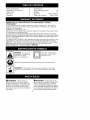
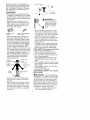
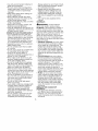
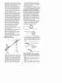
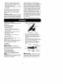
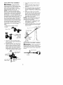
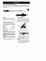
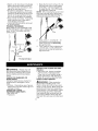
Instruction
Manual
J€:RAFTSMA#°J
PRUNER A'I-rACHMENT
Model No.
C944.514610
•
•
Safety
Assembly
•
•
Operation
Maintenance
•
Parts List
WARNING:
Read and follow all Safety Rules and Operating
Instructions
before first use of this product.
Sears Canada,
545001437
1/17/05
Inc., Toronto,
Ontario
M5B 2B8
Warranty Statement
Identification of Symbols
Safety Rules
Assembly
Operation
2
2
2
7
9
Maintenance
Service & Adjustments
Storage
Parts List
Parts and Ordering
1
13
14
Center Section
Back Cover
LIMITED TWO (2) YEAR WARRANTY ON CRAFTSMAN ® PRUNER
ATTACHMENT
For two (2) years from tile date of purchase, Sears Canada, Inc., will repair or
replace free of charge, at Sears option, parts which are defective as a result of
material or workmanship.
COMMERCIAL OR RENTAL USE:
Warranty on Pruner Attachment will be 90 days from the date of purchase if used
for commercial or rental purposes.
This warranty excludes expendable parts that become worn during normal use.
Warranty service is available by returning the Pruner Attachment to the nearest Sears
Service Centre/Department in Canada. This warranty applies only while this product
is in use in Canada.
This warranty is in addition to any statutory warranty and does not exclude or limit
legal rights you may have but shall run concurrently with applicable provincial
legislation. Furthermore, some provinces do NOT allow limitations on how long an
implied warranty will last, so the above limitations may not apply to you.
Sears Canada, inc., Toronto, Ontario MSB 2B8
DANGER!
Read and understand
the
instruction manuel before
using the pruner.
This pruner can
be dangerous! Careless or improper use can cause
serious or even fatal injury.
Always wear appropriate
DANGER!
protection
ear protection,
eye protection
Falling objects can cause severe
when operating
this unit.
,t%
dt_WARNING:
When using an
electric pruner or any other electric
gardening appliance, basic safety precautions must always be followed to
reduce the risk of fire, electric shock,
and serious injury. Read and follow all
instructions.
and head protection.
head injury, Wear head
Do not stand beneath
branch being
z't
WARNING:
Always disconnect
spark plug wire and place wire where it
cannot contact spark plug (or disconnect powerhead from power source) to
prevent accidental starting when setting
up, transporting, adjusting or making repairs except carburetor adjustments.
2
Because
apruner
isahigh-speed
wood-cutting
tool,special
safety
precautions
must
beobserved
toreduce
the
riskofaccidents.
Careless
orimproper
useofthistoolcancause
serious
or
even
fatalinjury.
PLAN AHEAD
• Read this manual carefully until you
completely understand and can follow
all safety rules, precautions, and operating instructions before attempting to
use the unit.
• Restrict the use of your pruner to
adult users who understand and can
follow safety rules, precautions, and
operating instructions found on the
unit and in this manual.
INSTRUCTION
SAFETY
MANUAL
ON THE
'_
INFORMATION
UNIT
Protection
Heavy Duty
GIoves
Safety
Shoes
50 feet
A
SEfy
etyHat
Fitting
Clothing
ZONE
i_1_..__.
• Wear protective gear. Always use
steel-toed safety footwear with nonslip soles; snug-fitting clothing; heavy,
long pants, and long sleeves; heavyduty, non-slip gloves; eye protection
such as non-fogging, vented goggles
or face screen; an approved safety
hard hat; and sound barriers (ear
plugs or mufflers) to protect your hearing. Regular users should have hearing checked regularly as engine noise
can damage hearing. Secure hair
above shoulder length. Secure or remove loose clothing and jewelry or
clothing with loosely hanging ties,
straps, tassels, etc.
Snug
HAZARD
""-.ai.
(15 meters)
DANGER:
Do not
use near e_ectrical
wires or power lines.
Keep pruner at least
30 feet (10 meters)
lines.
away from all power
• Do not handle or operate a pruner
when you are fatigued, ill, or upset,
or if you have taken alcohol, drugs,
or medication.
You must be in good
physical condition and mentally
alert. If you have any condition that
might be aggravated by strenuous
work, check with doctor before operating a pruner.
• Carefully plan your pruning operation
in advance. Do not start cutting until
you have a clear work area, secure
footing, and a planned retreat path.
FUEL SAFETY (for gas powerheads)
• Mix and pour fuel outdoors.
• Keep away from sparks or flames.
• Use a container approved for fuel.
• Do not smoke or allow smoking near
fuel or the powerhead.
• Avoid spilling fuel or oil. Wipe up all
fuel spills before starting the powerhead.
• Move at least 10 feet (3 meters) away
from fueling site before starting powerhead engine.
• Stop engine and allow to cool before
removing fuel cap.
• Remove fuel cap slowly.
ELECTRICAL
powerheads)
Safety Chaps
_
SAFETY
(for electric
_'WARNING:
Avoid a dangerous
environment. To reduce the risk of electrical shock, do not use in rain, in damp
or wet locations, or around swimming
pools, hot tubs, etc. Do not expose to
snow, rain, or water to avoid the possibility of electrical shock. Do not use on
wet surfaces. Do not handle extension
cord plug or unit with wet hands.
• Use only a voltage supply as shown
on the nameplate of the unit.
• Keep all parts of your body away
from the chain when the engine is
running.
• Keep children, bystanders, and animals a minimum of 50 feet (15 meters) away from the work area. Do
not allow other people or animals to
be near when starting or operating
the pruner.
3
• Avoid
dangerous
situations.
Donot
sharp
edges
orcorners.
Donotexuseinpresence
offlammable
liquids pose
cords
toheat,
oil,orwater.
orgases
toavoid
creating
afireor
• Keep
theextension
cordclear
ofoperator
andobstacles
atalltimes.
explosion
and/or
causing
damage
to
unit.
• Tiecordtocordretainer
andcon• Avoid
dangerous
environments.
necttorecessed
plugasshown
in
notuse
inunventilated
areas
orDo
thismanual
toprevent
damage
to
unitand/or
extension
cordandtorewhere
dustorexplosive
vapors
can
buildup.
ducethepossibility
oftheextension
• Toreduce
theriskofelectric
shock,
corddisconnecting
fromtheunitdurthepowerhead
mayhave
apolarized ingoperation.
plug(one
blade
iswider
than
theoth- • Donotattempt
torepair
unit.Inspect
theinsulation
andconnectors
onthe
er);ifso,itwillrequire
theuseofapolarized
extension
cord.
Theappliance powerhead
andextension
cordbefore
plugwillfitintoapolarized
extension each
use.Ifthere
isanydamage,
do
cordonlyoneway.
Iftheplugdoes
notuseuntildamage
isrepaired
by
notfitfullyintotheextension
cord,
reyourauthorized
service
dealer.
verse
theplug.
Iftheplugstilldoes
• Donotusethepowerhead
ifthe
switch
does
notturntheunitonand
notfit,obtain
acorrect
polarized
extension
cord.
Apolarized
extension offproperly.
Have
theunitrepaired
cordwillrequire
theuseofapolarized byyourauthorized
service
dealer.
walloutlet.
Thisplugwillfitintothepo- • Donotusewithdamaged
cordor
larized
walloutlet
onlyoneway.Ifplug plug.Ifpowerhead
isnotworking
as
does
notfitfullyintothewalloutlet,
itshould,
hasbeen
dropped,
damreverse
theplug.
Ifitstilldoes
notfit,
aged,
leftoutdoors,
ordropped
into
contact
aqualified
electrician
toinstall water,
return
ittoyourauthorized
sertheproper
walloutlet.
Donotchange vicedealer
forrepair.
theequipment
plug,
extension
cord
• Avoid
unintentional
starting
ofthe
receptacle,
orextension
cordplugin
unit.Never
carry
unitwithyourfinger
ontheswitch.
Besuretheswitch
is
anyway.
• Toreduce
riskofelectrical
shock,
use
intheOFF
position
andnever
touch
extension
cords
specifically
marked
theswitch
whenconnecting
extensioncord.
assuitable
foroutdoor
appliances
having
electrical
rating
notlessthan
• Unplug
theunitfromthepower
source
when
notinuse,before
servictherating
ofunit.Cord
must
be
marked
withsuffix
WV-A"
(inCanada ing,andwhen
changing
accessories
and/or
attachments.
WV").
Make
sure
yourextension
cord
isingood
condition.
Inspect
extension• Avoid
anybodycontact
withany
cordbefore
useandreplace
ifdamgrounded
conductor,
suchasmetal
aged.
Donotuseadamaged
cord.
fences,
orpipes,
toavoid
thepossiCord
insulation
must
beintact
withno
bilityofelectric
shock.
cracks
ordeterioration.
Plug
connec- • Ground
Fault
Circuit
Interrupter
torsmust
beundamaged.
Theexten- (GFCI)
protection
should
beprovidedonthecircuit
oroutlet
tobe
sioncordused
toreach
thepower
source
must
beheavy
enough
to
used
forthepowerhead.
Recepcarry
current
fromthepower
source
tacles
areavailable
having
built-in
thefulllength
oftheextension
cordto
GFCIprotection
andmaybeused
theunit.
Anundersized
extension
forthismeasure
ofsafety.
cordwillcause
adropinlinevoltage UNIT/MAINTENANCE SAFETY
resulting
inlossofpower
andover,_WARNING:
Disconnect powerheating.
Ifindoubt,
usethenext
heavier
gauge.
Thelower
thegauge head spark plug (or disconnect powernumber,
theheavier
thecord.
head from power source) before per• Donotusemultiple
cords.
forming maintenance.
• Donotabuse
cord.Never
carrythe
• Inspect entire unit before each use.
unitbytheextension
cordoryank
Replace damaged parts. Check for
extension
cordtodisconnect
unit.To
fuel leaks. Make sure all fasteners are
unplug,
grasp
theplug,
notthecord. in place and securely fastened.
Donotusecordasahandle,
close
a • Maintain unit according to recomdooroncord,
orpullcordaround
mended procedures.
• Useonlyrecommended
CraftsmanCR_
Always replace bar and chain immediparts
andaccessories.
ately if it becomes damaged, broken
or is otherwise removed.
• Besurechain
stopsmoving
when
engine
idles(seeCARBURETOR
AD- • Always stop the unit when work is
JUSTMENT
section
ofpowerhead
delayed or when walking from one
manual).
cutting location to another. Stop the
• Keep
others
away
whenmaking
carengine before setting the unit down.
buretor
adjustments.
• Use only in daylight or good artificial
• Never
starttheunitwiththeclutch
light.
housing
removed.
Theclutch
canfly
• Use only for jobs explained in this
manual.
offandcause
serious
injury.
• Keep
thehandles
driy,
clean,
andfree KICKBACK
ofoilorfuelmixture.
A0&WARNING:
Avoid kickback
• Keep
fuelandoilcaps,
screws,
and
fasteners
securely
tightened.
which can result in serious injury.
• Have
allmaintenance
andservice
not Kickback is the backward, upward or
explained
inthismanual
performed
by sudden forward motion of the guide
aSears
Service
Center.
bar occurring when the chain near the
upper tip of the guide bar contacts any
OPERATE
YOUR
PRUNER SAFELY
• Do not operate a pruner with one
hand. Serious injury to the operator,
helpers, bystanders or any combination of these persons may result
from one-handed operation. A pruner is intended for two-handed use.
• Operate the pruner only in a well-ventilated outdoor area.
• Do not operate pruner from a ladder
or in a tree.
• Do not use a pruner to cut down trees
or any portion of the tree trunk.
• Only use for pruning limbs or
branches overhead not greater than 4
inches (10 cm) in diameter.
• Never stand under the limb you are
pruning. Always position yourself out
of the path of falling debris.
• Do not cut small brush and saplings
with the pruner. Slender matter may
catch in the chain and be whipped toward you, pulling you off balance.
• Make sure the chain will not make
contact with any object while starting
the engine. Never try to start the unit
when the guide bar is in a cut.
• Do not put pressure on the pruner at
the end of the cut. Applying pressure
can cause you to lose control when
the cut is completed.
• Do not run the unit at high speed
when not pruning.
• If you strike or become entangled with
a foreign object, stop the engine immediately and check for damage.
Have any damage repaired by a
Sears Service Center before attempting further operations.
• Do not operate a pruner that is damaged, improperly adjusted, or not
completely and securely assembled.
object such as a log or branch, or
when the wood closes in and pinches
the chain in the cut. Contacting a foreign object in the wood can also result
in loss of control.
• Rotational Kickback can occur when
the moving chain contacts an object
at the upper tip of the guide bar. This
contact can cause the chain to dig
into the object, which stops the chain
for an instant. The result is a lightning
fast, reverse reaction which kicks the
guide bar up and back toward the operator.
• Pinch-Kickback
can occur when
the wood closes in and pinches the
moving chain in the cut along the
top of the guide bar and the chain is
suddenly stopped. This sudden
stopping of the chain results in a reversal of the chain force used to cut
wood and causes the pruner to
move in the opposite direction of the
chain rotation. The pruner is driven
straight back toward the operator.
• Pull-In can occur when the moving
chain contacts a foreign object in the
wood in the cut along the bottom of
the guide bar and the chain is suddenly stopped. This sudden stopping
pulls the pruner forward and away
from the operator and could easily
cause the operator to lose control of
the pruner.
REDUCE THE CHANCE OF
KICKBACK
• Recognize that kickback can happen. With a basic understanding
of
kickback, you can reduce the element of surprise which contributes to
accidents.
• Never
letthemoving
chain
contact
anyobject
atthetipoftheguide
bar.
• Keep
theworking
area
freefromobstructions
suchasother
trees,
branches,
rocks,
stumps,
etc.Eliminateoravoid
anyobstruction
that
yourchain
could
hitwhile
youare
cutting.
When
cutting
abranch,
do
notlettheguide
barcontact
branch
orother
objects
around
it.
• Keep
yourchain
sharp
andproperly
tensioned.
Aloose
ordullchain
can
increase
thechance
ofkickback
occurring.
Follow
manufacturer's
chain
sharpening
andmaintenance
instructions.
Check
tension
atregular
intervalswiththeengine
stopped,
never
withtheengine
running.
Make
sure
thebarclamp
nutissecurely
tightened
after
tensioning
thechain.
• Begin
andcontinue
cutting
atfull
speed.
Ifthechain
ismoving
ata
slower
speed,
thereisgreater
chance
ofkickback
occurring.
• Cutonebranch
atatime.
• Useextreme
caution
whenre-enteringa previous
cut.
• Donotattempt
cutsstarting
withthe
tipofthebar(plunge
cuts).
• Watch
forshifting
ofwood
orother
forces
thatcould
close
acutand
pinch
orfallintochain.
• UsetheReduced-Kickback
Guide
BarandLow-Kickback
Chain
specifiedforyourunit.
MAINTAIN
CONTROL
around the throttle handle whether
your are right handed or left handed.
• Stand with your weight evenly balanced on both feet.
• Stand slightly to the left side of the
pruner to keep your body from being
in a direct line with the cutting chain.
KICKBACK SAFETY FEATURES
The following features are included on
your pruner to help reduce the hazard
of kickback; however, such features
will not totally eliminate this danger.
As a pruner user, do not rely only on
safety devices. You must follow all
safety precautions, instructions, and
maintenance in this manual to help
avoid kickback and other forces which
can result in serious injury.
• Reduced-Kickback
Guide Bar, designed with a small radius tip which
reduces the size of the kickback
danger zone on the bar tip.
Reduced
Kickback
Symmetrical
Symmetrical
Guide
Bar
Guide
Bar
l_
Large
Radius
Contoured
Depth
Gauge
D Elongated
Low-Kickback
Chain
/
Tip
• Low-Kickback
Chain, designed with
a contoured depth gauge and guard
link which deflect kickback force and
allow wood to gradually ride into the
cutter.
_
and allows
to graduaUy
into cutter
f
Guard
an Obstruct
Not a Low-
Kickback
Link
wood
ride
Matedal
Chain
TRANSPORTING
AND STORAGE
• Do not grasp or hold exposed blade.
• Stop powerhead before leaving work
area.
• Allow powerhead and gearbox to cool
before storing or transporting it in a
vehicle.
• Store unit and fuel in area where fuel
vapors cannot reach sparks or open
• Keep a good, firm grip on the pruner
with both hands when the engine is
running and don't let go. A firm grip
will help you reduce kickback and
maintain control. Keep the fingers of
your left hand encircling and your
left thumb under the assist handle.
Keep your right hand completely
6
disorders
orabnormal
swellflames
fromwater
heaters,
electric culation
motors
orswitches,
furnaces,
etc.
ings.
Prolonged
useincoldweather
has
• Store
attachment
soblade
cannot
ac- been
linked
toblood
vessel
damage
in
otherwise
healthy
people.
Ifsymptoms
cidentally
cause
injury.
• Store
attachment
indoors,
outofreach occur
suchasnumbness,
pain,
lossof
ofchildren.
strength,
change
inskincolor
ortexture,
offeeling
inthefingers,
hands,
Ifsituations
occur
which
arenotcov- orloss
orjoints,
discontinue
theuseofthistool
eredinthismanual,
usecareand
andseekmedical
attention.
Anantigoodjudgment.
Ifyouneedassisvibration
system
does
notguarantee
the
tance,
contact
yourSears
Service
avoidance
ofthese
problems.
Users
Centre.
whooperate
power
tools
onacontinual
SPECIAL
NOTICE:
Exposure
tovibra- andregular
basis
must
monitor
closely
tions
through
prolonged
useofgasoline theirphysical
condition
andthecondipowered
hand
tools
could
cause
blood tionofthisunit.
vessel
ornerve
damage
inthefingers,
hands,
andjoints
ofpeople
prone
tocir- SAVE THESE INSTRUCTIONS
CARTON CONTENTS
Check carton contents
lowing list.
Model 0944.514610
• Pruner attachment
• Shoulder strap
• Upper shoulder strap
• Lower shoulder strap
spacer tabs)
• Shoulder strap clamp
• Attachment hanger
• Bar sheath
1.
against the fol-
Coupler
LOOSEN
clamp
clamp (with
screws
(2)
Examine parts for damage. Do not
use damaged parts.
NOTE: If you need assistance, or find
parts missing or damaged, contact
your Sears Service Centre.
ASSEMBLY
If received
TIGHTEN
2.
• Chain adjustment tool (bar tool)
• Hex wrench
• Bar and chain oil
_WARNING:
Loosen the coupler by turning the
knob counterclockwise.
as-
3.
4.
5.
Knob
Remove the shaft cap from the
pruner attachment (if present).
Position locking/release
button of
attachment into guide recess of
coupler.
Push the attachment into the coupler until the locking/release
button
snaps into the primary hole.
Before using the unit, tighten the
knob securely by turning clockwise.
Coupler
Primary Hole
\
// Guide Recess
sembled, repeat all steps to ensure
your unit is properly assembled and all
fasteners are secure.
TOOLS REQUIRED
• Hex wrench (provided)
INSTALLING
PRUNER ATTACHMENT
CAUTION:
When removing or installing attachments,
place the unit on a
flat surface for stability.
PP
Shaft
_WARNING:
Release
Button
Lower
Attachment
Make sure the lock-
ing/release button is locked in the primary hole and the knob is securely
tightened before operating the unit.
SHOULDER
STRAP
ASSEMBLY
WARNING:
Proper shoulder
strap and handle adjustments are required before use. The shoulder strap
clamp must be installed as shown
above the assist handle on the upper
shaft (powerhead end of unit).
NOTE: The lower shoulder strap
clamp has two spacer tabs attached.
These tabs are provided to adapt this
attachment for use with powerheads
that have a 1" (2.5 cm) diameter upper shaft (the shoulder strap clamp will
not tighten down securely on the 1"
(2.5 cm) diameter upper shaft without
using these spacer tabs). The tabs
must be broken off completely before
use and placed over the screw holes
on the lower shoulder strap clamp.
These tabs are not needed for powerheads with a 7/8" (2.2 cm) upper
shaft.
LOWER
CLAMP
SHOULDER
STRAP
3.
Insert two screws into the screw
holes.
4. Secure shoulder strap clamp by
tightening screws with the hex
wrench.
5. Try on shoulder strap and adjust for
fit and balance before starting the
engine or beginning a cutting operation.
6. Insert your right arm and head
through the shoulder strap and allow it to rest on your left shoulder.
Make sure the danger sign is on
your back and the hook is to the
right side of your waist.
NOTE: A one-half twist is built in the
shoulder strap to allow the strap to
rest flat on the shoulder.
7. Adjust the strap, allowing the hook
to be about 3 - 6 inches (7 - 15
cm) below the waist.
8. Fasten the strap hook to the upper
clamp and lift the tool to the operating position.
Shoulder
----a/_p_
_*
Spacer Tabs
positioned for use
oe 1" (2.5 Cm)
diameter
upper shaft
1.
2.
Place the upper shoulder strap
clamp over the upper shaft above
the handlebar.
Position the lower shoulder strap
clamp under the upper shaft and
align the upper and lower clamp
screw holes (use spacer tabs between upper and lower clamps if
necessary to secure clamp, i.e. for
1" (2.5 cm) diameter upper shaft).
Strap
Shoulder
Strap
Clamp
ADJUSTING
THE ASSIST HANDLE
_'WARNING:
When adjusting the
assist handle, be sure it remains directly above the coupler on the engine
end shaft to ensure proper balancing
of unit.
Assist Handle
./
Strap Clamp
POWERHEAD
END
Coupler
Lower Shoulder
Strap Clamp
|
!
• ATTACHMENT
_, END
Screws
KNOW
YOUR
PRUNER
ATTACHMENT
READ THiS iNSTRUCTiON MANUAL AND SAFETY RULES BEFORE OPERATING YOUR
PRUNER A]q-ACHMENq_ Compare the illustrations with your attachment to familiarize
yourself with the location of the various controls and adjustments. Save this manual
for future reference.
Hanger
__
Coupler
/
Bar oil fill cap
Shaft
Bar
PRUNER
The PRUNER is designed for removal
of limbs and branches overhead not
greater than 4 inches (10 cm) in diameter.
OPERATING THE COUPLER
Your powerhead is equipped with a
coupler which enables optional attachments to be installed. The optional attachments are:
Edger ...............
71-51157
Cultivator ............
71-51158
Blower ..............
71-51160
Brushcutter*
.........
71-51159
*not designed for use with electric
powerheads
Bar nut
CHAIN TENSION
It is normal for a new chain to stretch
during first 15 minutes of operation.
You should check your chain tension
frequently. See CHAIN TENSION in the
SERVICE AND ADJUSTMENTS section.
Upper Shaft
Coupler
Lower
Attachment
TIGHTEN
2.
_L, WARNING:
Always disconnect
powerhead spark plug (or disconnect
powerhead from power source) before
removing or installing attachments.
REMOVING PRUNER ATTACHMENT
(OR OTHER OPTIONAL ATTACHMENTS)
CAUTION:
When removing or installing attachments, place the powerhead
and attachment on a flat surface for stability.
1. Loosen the coupler by turning the
knob counterclockwise=
/
Chain
Press and hold
button.
Locking/Release
Button
Knob
the locking/release
/ o ,7 S m-
cup er _
Lower Attachment
3.
Upper Shaft
While securely holding the upper
shaft, pull the attachment straight
out of the coupler.
INSTALLING OPTIONAL ATTACHMENTS
1. Remove the shaft cap from the attachment (if present) and discard.
2. Position locking/release
button of
attachment into guide recess of
upper shaft coupler.
Primary
Coupler
3.
4.
Hole
' Guide Recess
OPERATING
POSITION
ALWAYS_WEAR:
_ , ,_,
Head
_'_
Protection
Eye
Protection
Locking/
Upper Release
Attachment
Shaft
Button
Push the attachment into the coupler until the locking/release
button
snaps into the primary hole.
Before using the unit, tighten the
knob securely by turning clockwise.
_WARNING:
ii
Make sure the lock-
ing/release button is locked in the primary hole and the knob is securely
tightened before operating the unit.
BAR AND CHAIN LUBRICATION
The bar and chain require lubrication.
The chain oiler provides continuous
lubrication to the chain and guide bar.
Be sure to fill the bar oil tank before
use (Capacity = 4.6 fl. oz./136 ml).
Lack of oil will quickly ruin the bar and
chain. Too little oil will cause overheating shown by smoke coming from
the chain and/or discoloration of the
bar. For maximum guide bar and
chain life, we recommend you use
CraftsmantR:. chain saw bar oil. If
Craftsman bar oil is not available, you
may use a good grade SAE 30 oil until
you are able to obtain Craftsman
brand. The oil output is automatically
metered during operation.
• Never use waste oil for bar and
chain lubrication.
• Always stop the engine before removing the oil cap.
INSTALLING ATTACHMENT
HANGER
An attachment hanger is provided for
storage when attachment is not in
use.
To install hanger on attachment:
1. Remove the shaft cap from the attachment (if present) and discard.
2. Press and hold the locking/release
button.
3. Push hanger onto the attachment
until the locking/release
button
snaps into the hole.
A_DANGER:
Do not extend arms
above shoulders while pruning. Do not
stand beneath branch being cut.
_;_,WARNING:
Always wear head,
eye, hearing, foot and body protection
to reduce the risk of injury when operating this unit.
When operating unit, clip shoulder
strap onto clamp, stand as shown and
check for the following:
• Extend your left arm and hold assist
handle with your left hand.
• Hold throttle grip with your right hand
with finger on throttle trigger.
• Keep engine end below waist level.
• Keep shoulder strap pad centered
on your left shoulder and danger
sign centered on your back.
• Maintain full weight of tool on your
left shoulder.
PRUNING
_,WARNING:
Be alert for and
guard against kickback. Do not allow
the moving chain to contact any other
branches or objects at the nose of the
guide bar when pruning. Allowing such
contact can result in serious injury.
IMPORTANT POINTS
• Work slowly, keeping both hands
firmly gripped on the pruner. Maintain secure footing and balance.
• Plan cut carefully. Check direction
branch will fall.
• Watch out for springpoles. Springpoles are small size limbs which can
catch the chain and whip toward you
or pull you off balance. Use extreme
caution when cutting small size limbs
or slender material.
lO
• Watch out for branches immediately
behind the branch being pruned. If
the chain hits the rear branch, damage to the unit may occur.
• Be alert for springback.
Watch out
for branches that are bent or under
pressure. Avoid being struck by the
branch or the pruner when the tension in the wood fibers is released.
• Keep a clear work area. Frequently
clear branches out of the way to
avoid tripping over them.
• Long branches should be removed
in several pieces.
PRUNING TECHNIQUE
When ready to cut, accelerate to full
throttle and apply a light cutting pressure. DO NOT use back and forth
sawing action.
1.
Make the first cut 6 inches (15 cm)
from the tree trunk on the bottom
of the limb. Use top of guide bar
to make this cut. Cut 1/3 through
the diameter of the limb.
NOTE: When making the second and
third cuts, rest the foot of the pruner
against the tree limb that is being cut
to prevent whipping of the branch.
2.
i
Second cut
3.
Third cut
Coil
Next, move 2 - 4 inches (5 - 10
cm) farther out on the limb and
make a second cut all the way
through the limb.
Then, make a final cut leaving a 1
- 2 inch (2.5 - 5 cm) collar from
the trunk of the tree to avoid damage to the tree.
First cut
Pruning
technique
_WARNING:
Always stop unit
and disconnect spark plug wire (or
disconnect powerhead from power
source) before performing maintenance.
CHECK FOR DAMAGED OR
WORN PARTS
Contact a Sears Service Center for
replacement of damaged or worn
parts.
• Oil tank - Discontinue use of pruner
attachment if oil tank shows signs of
damage or leaks.
CHECK FOR LOOSE
FASTENERS AND PARTS
• Bar clamp nut
• Fasteners
INSPECT AND CLEAN UNIT AND
DECALS
• After each use, inspect complete
unit for loose or damaged parts.
Clean the unit and decals using a
damp cloth with a mild detergent.
• Wipe off unit with a clean dry cloth.
CHECK CHAIN TENSION
,_ WARNING:
Wear protective
gloves when handling chain. The
chain is sharp and can cut you even
when it is not moving. Make chain adjustments with lower end supported.
Chain tension is very important. Chains
stretch during use. This is especially
true during the first few times you use
your pruner. Always check chain tension each time you use and refuel your
unit.
11
1=Usethescrewdriver
endofthe
chain
adjustment
tool(bartool)to
move
chainaround
guide
barto
ensure
kinks
donotexist.
The
chain
should
rotate
freely.
Chain
Adjustment
Tool
Guide
Bar
2= Loosen bar clamp nut until it is
finger tight against the bar clamp.
Adjusting Screw
Bar clamp nut
3= Turn adjusting screw clockwise
until chain solidly contacts bottom
of guide bar rail. Then, turn adjusting screw an additional 1/4 turn.
Adjusting Screw - 1/4 Turn
4.
5.
6.
Using bar tool, roll chain around
guide bar to ensure all links are in
bar groove.
Lift up tip of guide bar to check for
sag. Release tip of guide bar, then
turn adjusting screw 1/4 turn clockwise. Repeat until sag does not
exist.
While lifting tip of guide bar, tighten
bar clamp nut securely with tile bar
tool.
CHECK CHAIN SHARPNESS
A sharp chain makes wood chips. A
dull chain makes a sawdust powder
and cuts slowly. See CHAIN SHARPENING in the SERVICE AND ADJUSTMENTS section.
BAR MAINTENANCE
If your pruner cuts to one side, has to
be forced through the cut, or been run
with an improper amount of bar lubrication it may be necessary to service
your bar. A worn bar will damage your
chain and make cutting difficult.
After each use, ensure ON/OFF switch is
in the OFF position, then clean all sawdust from the guide bar and sprocket
hole.
To maintain guide bar:
• Move ON/OFF switch to the OFF position and disconnect spark plug (or disconnect powerhead from power
source).
• Loosen and remove bar clamp nut
and chain brake. Remove bar and
chain from pruner.
• Clean the oil holes and bar groove
after each 5 hours of operation.
Remove Sawdust From
Guide Bar Groove
\
OilHoles
• Burringofguide bar rails
isa normal
process of rail wear. Remove these
burrs with a flat file.
• When rail top is uneven, use a flat
file to restore square edges and
sides.
_-,LJrr_
7.
8.
9.
Use the screwdriver end of the bar
tool to move chain around guide
bar.
If chain does not rotate, it is too
tight. Slightly loosen bar clamp nut
and loosen chain by turning the adjusting screw 1/4 turn counterclockwise. Retighten bar clamp nut.
If chain is too loose, it will sag below
the guide bar and needs to be tightened following above procedure.
_WARNING:
DO NOT operate the
pruner if the chain is loose. If the pruner is operated with a loose chain, the
chain could jump off the guide bar and
result in serious injury.
and Sides
I U I
File Square
Rail Edges_r] l Nl
Worn Groove
Correct Groove
Replace guide bar when the groove is
worn, the guide bar is bent or cracked,
or when excess heating or burring of
the rails occurs. If replacement is necessary, use only the guide bar specified for your pruner in the repair parts
list.
LUBRICATION
Fill
Cap
• See GUIDE BAR AND CHAIN OiL under the OPERATION section.
12
z_
,_LWARNING:
Always stop unit
and disconnect spark plug wire (or
disconnect powerhead from power
source) before performing maintenance, service, or adjustments except
for carburetor adjustments.
Cutters
Depth Gauge
Drive Links
CHAIN SHARPENING
Chain sharpening is a complicated task
that requires special tools. We recommended you refer chain sharpening to a
professional chain sharpener.
CHAIN REPLACEMENT
,_
WARNING:
Wear protective
gloves when handling chain. The
chain is sharp and can cut you even
when it is not moving.
It is normal for a new chain to stretch
during the first 15 minutes of operation.
You should recheck your chain tension
frequently and adjust the chain tension
as required. See CHAIN TENSION section.
Replace the old chain when it becomes
worn or damaged. Use only the LowKickback replacement chain specified in
the repair parts list.
TO REPLACE CHAIN:
1. Move ON/OFF switch to tile OFF
position and disconnect spark plug
(or disconnect powerhead from
power source).
2. Remove bar clamp nut.
3. Remove bar clamp.
4. Turn adjusting screw by hand
counterclockwise
until adjusting
pin just touches the stop.
5. Slide guide bar behind sprocket
until guide bar stops against
sprocket.
6. Remove the old chain.
7. Carefully remove new chain from
package. Hold chain with the drive
links as shown.
8.
Place chain over sprocket, fitting
the drive links in the sprocket.
9. Fit bottom of drive links between the
teeth in the sprocket in the nose of
the guide bar.
10. Fit chain drive links into bar
groove.
11. Pull guide bar forward until chain is
snug in guide bar groove. Ensure
all drive links are in the bar groove.
12. Now, install bar clamp making sure
the adjusting pin is positioned in
the lower hole in the guide bar.
Lower Hole
S
/
Guide Bar
@
Adj_
Tip of
Bar
13. Install
tighten
ther at
CHAIN
CUTTERS MUST FACE IF'
DIRECTION
QF
ROTATION
J
/
bar clamp nut and finger
only. Do not tighten any furthis point. Proceed to the
ADJUSTMENT section.
CHAIN ADJUSTMENT
See CHECK CHAIN TENSION in MAiNTENANCE section.
13
all.WARNING:
Perform the follow-
ing steps after each use:
• Allow attachment
to cool before
storing or transporting.
• Store attachment with all guards in
place. Position attachment so that
any sharp object cannot accidentally
cause injury.
• Store the attachment in a dry, well
ventilated area out of the reach of
children.
SEASONAL
STORAGE
Prepare attachment for storage at end
of season or if it will not be used for 30
days or more.
If your pruner attachment is to be
stored for a period of time:
• Clean the entire attachment.
• Lightly oil external metal surfaces
and guide bar.
• Oil the chain and wrap it in heavy
paper or cloth.
• Check entire attachment for loose
screws or nuts. Replace any damaged, worn or broken parts.
• At the beginning of the next season,
use only fresh fuel having the proper
gasoline to oil ratio.
14