1
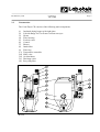
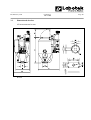
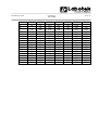
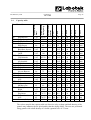
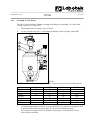
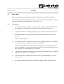
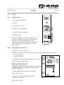
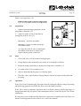
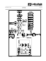
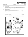
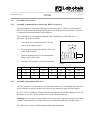
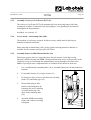
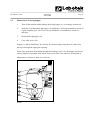
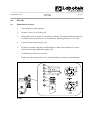
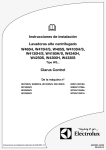
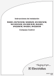
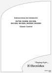
MANUAL
Conti-Dryer
CD 25-600
Serial No. ...................
ISO 08.01.02.12.GB
986041
Rev. February 1996
Rev.February 1996
Conti-Dryer
CD 25-600
Page 1
1.0
CONTENTS
2.0
GENERAL INFORMATION
3
2.1
2.2
2.3
2.4
2.5
2.6
Use
Limitations
Construction
Standards, directives, instructions etc. used
Operating principles
Certificates
3
3
4
5
5
6
3.0
TECHNICAL DATA
8
3.1
3.2
3.3
3.4
3.5
3.6
Technical specifications
Typeplate
Dimensioned sketches
Capacity table
Security measures
Noise level
8
9
10
12
13
14
4.0
ASSEMBLY / DISASSEMBLY
15
4.1
4.2
4.3
4.4
4.5
4.6
4.7
4.8
Assembly
Disassembly
Connections
Control
Adjustment
Start
Operation
Stop
15
17
17
18
19
19
19
21
5.0
ACCESSORIES
22
5.1
5.2
List of accessories
Assembly of accessories
22
23
6.0
MAINTENANCE
25
6.1
6.2
6.3
Maintenance of filters
Maintenance of magnet grid
Maintenance of drying hopper
25
26
27
Rev.February 1996
Conti-Dryer
CD 25-600
Page 2
7.0
TROUBLESHOOTING
28
7.1
7.2
7.3
The machine does not start/dies
The machine runs, but heats insufficiently
The machine dries insufficiently (temperature ok)
28
28
30
8.0
REPAIR
31
8.1
Replacement of heater
31
9.0
INDEX
10.0
SPARE PARTS
NB!
All electrical diagrams can be found in the pocket in the back of the manual.
Rev.February 1996
2.0
GENERAL INFORMATION
2.1
Use
Conti-Dryer
CD 25-600
Page 3
The Conti-Dryer CD is a hot air dryer designed for drying of free-flowing plastics raw
material in the form of granules. The Conti-Dryer is able to dry in batches or continuously.
2.2
Limitations
The Conti-Dryer CD operates on ambient air. The final residual humidity that is obtainable
will therefore always depend on the ambient temperature and relative humidity.
To be able to operate continuously the Conti-Dryer CD must feature an automatic vacuum
conveyor on the lid.
The Conti-Dryer CD cannot be used for materials in powder or liquid form or for living
organisms. The CD must be operated by a qualified operator only and according to the
correct procedures. The CD must be used only for the purposes described in this manual.
The machine must not be used in areas of explosive hazard.
Rev.February 1996
2.3
Conti-Dryer
CD 25-600
Construction
The Conti-Dryer CD consists of the following main components:
(1)
(2)
(3)
(4)
(5)
(6)
(7)
(8)
(9)
(13)
(24)
(30)
(31)
(81)
Insulated drying hopper with sight glass
Lid with flange for Con-Evator vacuum conveyor
Heater
Filter housing
Fresh air valve
Control
Blower
Intake filter
Filter bag
Temperature controller
Slide valve
Air distributor
Discharge valve
Recycling filter
R1620
Page 4
Rev.February 1996
2.4
Conti-Dryer
CD 25-600
Page 5
Standards, directives, instructions etc. used
EN - 60204 - 1 / IEC - 204 – 1
IEC – 529
AT - instruction no. 2.2.0.1 of October 1990
Directive no. 73/23/EEC (low tension directive)
Directive no. 89/336/EEC changed by directive no. 92/31/EEC (EMC-directive).
Directive no. 89/392/EEC changed by directive no. 91/368/EEC (machine directive).
2.5
Operation principles
When the machine is turned on the blower (7) starts. The air goes pass the heater (3), via the
drying hopper (1) and the filter housing (4) in a partly closed circuit.
When the air in the sytem has reached the temperature preset on the temperature controller
(13), the heater (3) turns off.
To aid to evaporation of water vapour being released from the plastic granules, the air is
exchanged by means of a fresh air valve (5). Fresh air is taken in through the intake filter (8),
and the varm, moisty air leaves the system through the filter bag (9).
The fresh air valve (5) is continuously adjustable to ensure an optimum ratio between
recycled and fresh air.
R1621
Rev.February 1996
2.6.
Certificates
2.6.1
EQ-Net Certificate
Conti-Dryer
CD 25-600
Page 6
Rev.February 1996
2.6.2
ISO Certificate
Conti-Dryer
CD 25-600
Page 7
Rev.February 1996
3.0
TECHNICAL DATA
3.1
Technical specifications
Conti-Dryer
CD 25-600
Conti-Dryer
Page 8
CD
CD CD CD CD CD CD
25
50
90
180 350 500 600
Supply voltage
3 x 220/380/415/440 V 3 x 380/415/440 V
50-60 Hz
50-60 Hz
Control voltage 24 V via transformator
24 Volt AC via transformer
Total load, kW
1.87/ 2.87/ 6.1/ 7.5/ 12.2/ 18.0/ 19.0/
1.95 2.93 6.3
7.8 12.5 18.6 19.6
Blower motor 50/60 Hz
0.37/ 0.37/ 1.1/ 1.5/ 2.2/ 4.0/ 4.0/
0.43 0.43 1.3
1.8
2.5
4.6
4.6
Heater, kW
1.5
2.5
5
6
10
14
15
Average power consumption kW at 90° 0.9
1.4
2.5
4.6
8.1
12
12
Airflow m3/h 50-60 Hz
at a counter pressure of 0.1 bar
25
50
90
170 300 440 440
Raw material hopper
capacity, litre
25
50
90
180 350 500 600
Noise level, dB(A)
60
60
65
70
75
75
75
Power cable, m
3
3
3
5
5
5
5
Net weight, kg
43
52
85
91
175 225 240
Maximum drying temperature for standard units: 140° C.
Rev.February 1996
3.2
Conti-Dryer
CD 25-600
Page 9
Typeplate
The typeplate is located on the side of the control containing all electrical data for
connections. The serial number consists of a code (A)(B), a type number (C) and a serial
number (D).
3.2.1
Code (A) and (B):
The first and last digit (A) in the code indicate the year in which the machine was produced.
E.g. 9ST5 = 1995.
The two middle letters (B) in the code indicate whether the machine is a standard model or not.
ST = Standard apparatus
SP = Special construction meeting the customer’s requirements
HT = HT/LT model
EX = Special mark for remote controls
ES = Special mark for substitute controls
3.2.2
Type (C)
The type number consists of two digits that indicate the machine type:
CD 25:
CD 50:
CD 90:
CD 180:
CD 350:
CD 500:
CD 600:
3.2.3
91
92
93
94
95
96
97
Serial number (D)
The serial number consists of five digits that refer to the exact production number of the
machine.
The serial number consists of a code (A)(B), a type number (C) and a serial number (D).
3.2.4
Serial number (D)
The serial number consists of five digits that refer to the exact production number of the
machine.
R1645
Rev.February 1996
3.3
Dimensioned sketches
All measurements in mm.
R1626
Conti-Dryer
CD 25-600
Page 10
Rev.February 1996
A
B
C
D
E
F
G
H
I
K
L
M
N
O
P
R
S
T
Conti-Dryer
CD 25-600
CD 25
750
570
490
Ø395
80
176
Ø50
120
58
13
Ø9
120
150
125
160
M8
250
CD 50
930
340
640
490
Ø360
80
176
Ø50
120
58
13
Ø9
120
150
125
160
M8
250
CD 90
1060
340
810
580
Ø500
122
216
Ø70
172
84
13
Ø13
120
150
125
160
M8
415
CD 180
1490
340
890
580
Ø545
122
216
Ø70
172
84
13
Ø13
120
150
125
160
M8
415
Page 11
CD 350
1600
340
1235
810
Ø790
158
278
Ø102
236
118
17
Ø17
120
150
125
160
M8
770
CD 500
1980
340
1235
810
Ø790
158
278
Ø102
236
118
17
Ø17
120
150
125
160
M8
770
CD 600
340
1235
810
Ø790
158
278
Ø102
236
118
17
Ø17
120
150
125
160
M8
770
Rev.February 1996
43
36
36
86
72
72
168
140
140
240 288
200 240
200 240
7.5
15
27
54
105
150
180
80
7
13.5
24
48
93
133
160
2.25
120
7
13.5
24
48
93
133
160
2.25
65-70
7
13.5
24
48
93
133
160
2.25
2.25
2.75
2.75
80
120
75
120
7 13.5 24
6
12 21.5
5.5 11 19.5
5.5 11 19.5
48
43
39
39
93
84
76
76
133 160
120 144
109 131
109 131
3.0
3.0
3.25
75
100
80
1.0
5
5
4.5
10
10
9
18
18
16.5
36
36
33
70
70
65
100 120
100 120
92 111
3.25
3.25
75-85
90
1.0
4.5
4.5
9
9
16.5
16.5
33
33
65
65
92
92
111
111
3.5
80
0.1
4
8.5 15.5
31
60
86
103
3.75
75-85
1.0
4
8
14.5
29
56
80
96
4.5
70-75
2.0
3.5
6.5
12
24
47
67
80
4.5
5.5
70-75
65-70
2.0
3.5
3
6.5
5.5
12
10
24
20
47
38
67
55
80
65
2.0
80
2.25
0.4
0.5
1.0
CD 600
24
20
20
65-90
90
80
CD 90
12
10
10
1.25
1.5
1.5
CD 50
CD 550
CD 180
Initial moisture
content
CL 25
CD 350
Polyethylene
Polypropropylene
Polystyrene
Polystyrene
High impact
ABS Acrylonitrile
Butadiene Styrene
PPO Polyphenylene
Oxide
PVC Poly
Vinylchloride
SAN Styrene
Acrylonitrile
PI
Polymide
CA
Cellulose Acetate
PSU Polysulfene
CAB CelluloseAcetate Butrane
POM Polyacetal
AN
Barex
PA
Polyamide 6, 6/6
6.10
PUR Polyurethane
PMMA Polymethyl
Methacrylate
PE
Polyethylene,
Black
CP
Cellulose
Propionate
PA
Polyamide 6/6, 6/6
6.10
Inomere (Surlyn A)
Recommended
drying temp.
Raw Material
PE
PP
PS
SB
Page 12
Capacity table
Drying time in
hours
3.4
Conti-Dryer
CD 25-600
The values stated in the capacity table are directive only, as shape and bulk density of the
granule may influence the air speed and by that the drying ability. The tests are performed
using granule with a bulk density of 0.6 and a granular size of 2-3 mm.
Rev.February 1996
Conti-Dryer
CD 25-600
Page 13
Drying temperatures and times are directive only, as these can vary from one producer to
another. Therefore it is advisable always to check with the supplier of the relevant raw
material.
The capacities stated are obtained at an ambient temperature of 20° C and a relative
humidity of 65% under which conditions a final moisture content of 0.04% is obtainable.
A higher relative humidity could be the reason as to why the stated value cannot be
obtained in all cases.
Certain materials will require a lower residual humidity than the one stated, especially in
matters of extrusion, and in such cases it will be necessary to use a dry air dryer type
DDL, DDM or DCD.
3.5
Security measures
3.5.1
Con-Evator support
All CD units, except for the smallest type, are equipped with a bracket supporting the
Con-Evator vacuum conveyor when the lid is open.
3.5.2
Overtemperature protection
The electronic temperature controller is equipped with an electronic overtemperature
protection which automatically cut off the control current of the heater, if the temperature
rise 12° C above adjusted value. In case of overtemperature condition, a red diode on the
control panel lights up.
The overtemperature protection is reset by switching the main switch of the machine on
and off.
3.5.3
Fire protection (see fig. 8.1)
All Conti-Dryer units are equipped with a fire protection (83) in the form of a thermistor
(bi-metal) of 210° C.
At a temperature above 210° C the circuit-breaker overload of the heater in the control
is released thus cutting off main power to the heater. When the thermistor is sufficiently
cooled and still in working condition, the protection is reset on the release button of the
circuit breaker overload by switching the main switch of the machine off and then on.
Rev.February 1996
3.5.4.
Conti-Dryer
CD 25-600
Page 14
Heater (see fig. 2.3)
At operation at high temperatures the filter housing (4) and the heater (3) are able to
reach extremely high temperatures. Signs warning against high-temperature condition are
placed accordingly.
3.6
Noise level
The Conti-Dryer has the following noise level according to DS/ISO-3746:
Type
DB(A)
CD 25
60
CD 50 CD 90
60
65
CD 180 CD 350
70
75
CD 500 CD 600
75
75
Rev.February 1996
4.0
ASSEMBLY / DISASSEMBLY
4.1
Assembly
Conti-Dryer
CD 25-600
Page 15
The Conti-Dryer is designed for assembly directly on the processing machines replacing
the machine hopper.
If the Conti-Dryer flange does not match the hopper flange on the processing machine, it is
necessary to make an intermediate flange.
4.1.1
Assembly flange
The Conti-Dryer is supplied fully equipped. The machine is lifted in the transversed lifting
fixture (10) on the frame, as shown in the sketch.
R1628
WARNING: Lifting, as illustrated, must be done only with the hopper being depleted.
Assembly dimensions: see dimensioned sketch section 3.3
Rev.February 1996
4.1.2
Conti-Dryer
CD 25-600
Page 16
Assembly of Con-Evator
The lid (2) on the machine features a cutting and a flange for assembly of a Con-Evator
vacuum conveyor (11) type PGT.
1.
Disassemble the cover plate (12) on CD lid.
2.
Fix the vacuum conveyor (11) bolt holes matching on the lid, using 4 bolts M8.
R1630
The below table indicates which types of Labotek vacuum conveyors that can be fitted on CD.
CD 25
CD 50
CD 90
CD 180
CD 350
CD 500
CD 600
*
MF 98*
X
X
X
PGT 4
X
X
X
X
X
X
X
PGT 61
PGT 9
X
X
X
X
X
X
(X)
(X)
X
X
X1
An intermediate flange (225027) is used to fit MF 98. For reasons of weight the PGT
9 should be fitted only on CD 90 and CD 180 in their divided execution.
For reasons of weight the PGT 9 should be fitted only on CD 90 and CD 180 in
their divided execution.
Rev.February 1996
4.2
Conti-Dryer
CD 25-600
Page 17
Disassembly
If it is required to disassemble the Conti-Dryer, all material must be discharged first.
Power must be disconnected, and Con-Evator, if attached, disassembled. The Conti-Dryer
can now be handled in the lifting fixture (10). See fig. 4.1.1
4.3
Connections
1.
Check that the voltage available correspond to the voltage requirement indicated on
the typeplate. The typeplate is located on side of the control (see point 3.1).
2.
Connect the machine according to diagram. To be found in the back of the manual.
3.
Turn on the machine using the main switch and check that the blower runs arrow
directed.
If not, switch two phases.
4.
If a vacuum conveyor is attached, it can be power supplied from the CD. Terminals
have been set out for this purpose (terminal 7.8.9 and PE).
Check revolving direction at start-up of the vacuum conveyor. A label is attached
on the ventilation cover where the long arrow indicates conveying and the short one
filter cleaning. (See also manual for Con-Evator).
5.
A potential free contact is available for connection of an external alarm. See diagram
in the pocket in the back of the manual.
6.
The control which is usually fixed on the unit can be placed remotely up to 10 m
from the unit.
7.
By remote placing the control must be turned vertically placed, like on the unit.
Rev.February 1996
4.4
Control
4.4.1
Control buttons
Conti-Dryer
CD 25-600
Page 18
(13) Temperature controller
(14) Fuse
(15) Diode - power on
(16) Diode - overtemperature
(17) Diode - motor overloaded
(18) Main switch
On CD 25-180 units the whole control box can
be tilted to an angle of 90 degrees thus providing
easy access to all front components. On CD
350-600 units the control front plate is integrated
in the cabinet. Access to components via side
door in cabinet.
4.4.2
R1632
Temperature controller (13)
Temperature adjusting button (19)
Button for adjusting temperature. Temperature scale values displayed in both °C and °F.
°C: Large, white text
°F: Small, green text
Adjusting the drying temperature in the area 80-130° C.
Hysteresis adjusting button (20)
Button for adjusting hysteresis
(temperature fluctuation area).
The button is placed on side of the temperature controller.
The button for hysteresis adjustment is factory preset
to approx. mid area.
Further adjustments are usually not required.
Diode voltage on (21)
«Power on» indicates that the temperature
controller is connected.
Diode, heater on (22)
R1633
Rev.February 1996
Conti-Dryer
CD 25-600
Page 19
Diode, overtemperature (23)
Diode giving signal if current temperature
is 12° C (35°F) above/below set temperature.
4.5
Adjustment
1. Adjust required drying temperature on the
temperature controller (13)
2. Adjust air intake on top of the filter by
turning the fresh air valve (5).
Maximum = full fresh air intake
Minimum = lowest air intake and major
recirculation share
As a start the fresh air valve is adjusted in
the middle of the interval. Adjust until
required drying result is achieved.
4.6
4.7
R1634
Start
1.
Close slide valve (24) in bottom of drying hopper.
2.
Charge hopper either manually or by means of an attached Con-Evator.
3.
Required drying temperature is adjusted on temperature controller (13).
4.
Use main switch (18) to connect power.
5.
Wait recommended drying time (see capacity table).
6.
The slide valve (24) in bottom of drying hopper can now be opened, and production
set going.
Operation
If the CD is used for batch drying, the hopper must be recharged whenever empty by turning
off the drying apparatus and follow the above described start procedure.
If the CD is used in continuous operation with Con-Evator attached, the drying hopper is
charged automatically pari passu with consumption which is controlled by the Con-Evator
bottom flap.
It is necessary only to make sure that material is continuosly available to the Con-Evator. An
alarm for missing material can be fitted. (see Con-Evator manual).
Rev.February 1996
R1920-gb
Conti-Dryer
CD 25-600
Page 20
Rev.February 1996
4.7.1
Conti-Dryer
CD 25-600
Page 21
Change of material
The stop/start procedure applies to change of material also.
At change of material it is recommended to clean out dust and regrind from the hopper.
Remaining granulate can be removed by opening the slide valve. Dust can be removed by
opening the lid or by disassemble the sight glass and clean out using compressed air - the
discharge valve (31) must be kept open during this procedure.
4.8
Stop
1.
If attached stop Con-Evator on main switch placed on its control.
2.
Discharge the CD drying hopper either by running
it dry or by discharging it through the discharge
valve (31) in the cone of the drying hopper.
It is recommended to leave the CD blower on
during discharging, as it will facilitate discharging.
3.
When the drying hopper has run empty, or if it
is required to interrupt production, the CD is
stopped on the main switch (18).
4.
At long production stops it is recommended
to lower the temperature to avoid “overdrying”
of the material.
R1635
Rev.February 1996
5.0
Conti-Dryer
CD 25-600
Page 22
ACCESSORIES
The following standard accessory is available to the machine. Labotek will always be at
your disposal on development of special parts.
5.1
List of accessories
Mounting base featuring a magnet and a manual slide valve
(26)
Pneumatic slide valve
(24a)
Con-Evator
(11)
Level control + alarm lamp
(38a)(38b)
Assembly fixture for Mini Master-Batcher (chamber dosing)
(39)
R1637
Rev.February 1996
Conti-Dryer
CD 25-600
Page 23
5.2
Assembly of accessories
5.2.1
Assembly of mounting base (26)(see fig. R1637 section 5.1)
The mounting base, featuring a sight glass and a magnet grid, is fitted to avoid magnetic
particles in the raw material from entering the screw of the production machine, or when it
is required to add masterbatch or other additives.
The mounting base is as standard equipped with a manually operated slide valve. A
pneumatic one is also available.
1.
Close slide valve and disassemble CD from
frame / processing machine.
2.
First assemble intermediate flange / slide valve
(24a) on the machine.
3.
Then fit mounting base (26) on intermediate
flange / slide valve (24a).
4.
Assemble CD on frame / processing machine.
R1693
5.2.2
DDL 25
DDL 50
DDL 90
DDL 180
DDL 350
DDL 500
DDL 600
H
45
45
60
60
120
120
120
I
60
60
80
80
118
118
118
J
120
120
182
182
236
236
236
Assembly of pneumatic slide valve
On CD 350-600 it is recommened to fit a pneumatic slide valve. A manually operated valve
can be difficult to operate on these unit owing to the amount of material in the hopper.
If CD 25-180 is assembled on frame, then first assemble an intermediate flange prior to the
pneumatic valve. On CD 350-600 the valve can be fitted immediately.
Warning: Do not connect compressed air to the valve before appropiate measures are taken
to hinder unintended access to the slide valve, so eliminating the risk of bodily injury.
The slide valve is factory-labelled against sharp edge mechanism.
Rev.February 1996
5.2.3
Conti-Dryer
CD 25-600
Page 24
Assembly of conveyor Con-Evator PGT (11).
The conveyor Con-Evator PGT will automatically keep the drying hopper full, thus
creating an even flow of material in the drying hopper, corresponding to the material
consumption in the production.
Assembly, see section 4.1.2
5.2.4
Level control + alarm lamp (38a) (38b)
The machine is not factory prepared for this accessory which must be fitted by an
authorized Labotek technician.
Please note that an alarm lamp (38b), giving signal at missing material condition, is
available for the vacuum conveyor type Con-Evator.
5.2.5
Assembly fixture for Mini Master-Batcher (39)
This fixture applies when it is required to dose directly into the Conti-Dryer using
Labotek’s chamber dosing unit MMB. Dosing problems may occur, as the pressure in the
Conti-Dryer may go out through the mounting base and up through to the hose to the
MMB. A special pressure compensation kit is available from Labotek in such case.
1.
It is a condition that a mounting base (26) is assembled between CD and production
machine.
2.
Fit assembly fixture (39) on pipe chassis (93).
3.
Fit using two clips (91) hose (90) between assembly
fixture (39) and outlet pipe (92).
5.
Disassemble plug in inlet
branch of mounting base by
loosening the screw retaining
it. Put the outlet pipe (92)
down in the mounting base
(26).
6.
Assemble MMB on assembly
fixture and connect according
to diagram.
R1640
Rev.February 1996
Conti-Dryer
CD 25-600
6.0
MAINTENANCE
6.1
Maintenance of filters
Page 25
The CD features the following filters:
Designation
Type of filter Check-up intervals
Check-up procedure
Intake filter (8)
Wire mesh
As required
Check-up and clean using air.
At insufficient result, wash the
filter.
Recirculation
filter (81)
Cartridge
(paper)
As required
Recommendation:
50 hours
Check-up and clean using air.
At insufficient result, replace
the filter
Filter bag (9)
Polyester
As required.
Recommendation:
50 hours
Check-up and clean using air.
At insufficient result, replace
filter.
Return air
filter (105)
Wire mesh
As required:
Recommendation:
50 hours
Check-up and clean using air.
At insufficient result, replace
replace filter.
R1643
Rev.February 1996
6.2
Conti-Dryer
CD 25-600
Page 26
Maintenance of magnet grid (accessory)
The magnet grid (25) is placed in the mounting base (26)(accessory). The grid
automatically picks up magnetic material, thus avoiding damage of screw of production
machine. Inspect magnet grid at least once a year.
1.
Close slide valve (24)
2.
Remove finger screw (27) on glass lid.
Warning: The granulate in the bottom of the hopper may be warm.
3.
Remove magnet grid (25) and clean it using e.g. compressed air.
R1636
Rev.February 1996
6.3
Conti-Dryer
CD 25-600
Page 27
Maintenance of drying hopper
1.
Turn off the machine and discharge the drying hopper (1) as at change of material.
2.
Open lid (2), disassemble and remove air distributor (30) being mounted by means of
a quick coupling (28). (On CD 25 the air distributor is assembled by means of a
split pin).
3.
Disassemble sight glass (29).
4.
Close slide valve (24).
Hopper (1) and air distributor (30) can now be cleaned using compressed air either from
the top or through the sight glass opening.
Please note, that when discharging through the discharge valve (31) the hopper may not be
entirely depleted, as granulate may remain on top of the slide valve and has to be disposed of.
Maintenance of return air filter see section 6.1
R1641
Rev.February 1996
7.0
TROUBLESHOOTING
7.1
The machines does not start / dies
Conti-Dryer
CD 25-600
Page 28
Signal: green light does not light up
Cause
Remidial action
1.
No power
Check main connections / fuse
2.
Fuse on PCB defective
Replace
3.
Circuit breaker overload OFM1
for motor cut out
Reset QFM1 (see 6.1)
4.
Fuses on primary side of
transformator cut out
Replace FU1/FU2
5.
Fuse for secondary circuit cut out
Replace FU 3
If a fuse cuts out more than twice, call
for a repairman
Signal: green lamp lights up, red over-load lights up
Cause
Remidial action
Circuit breaker overload QFM1
Open control box, reset red button on
QFM1
Possible causes for cut out of circuit breaker overload for motor:
- phase missing
- motor overloaded
- filter clogged
- worn down
- blocking
7.2
The machine runs, but heats insufficiently
A: Signal: green lamp lights up + red overtemperature light on
Cause
Remidial action
Overtemperature control cut out:
Leave it to cool down
Overtemperature control defective
Replace
Rev.February 1996
Conti-Dryer
CD 25-600
Page 29
Temperature controller defective
Replace
Thermistor defective
Replace
Control PCB etc. defective
Replace
B. Signal: Green lamp lights up + green diode on temperature controller
Cause
Remidial action
The temperature controller does not
activate the heater
1.
Circuit breaker overload for heater
cut out
Reset QFM2. At recurrences call for a
repairman.
2.
Temperature controller defective
Replace
3.
Heater defective
Replace
C: Signal: Green lamp lights up + temperature controller no light
Cause
Temperature controller defective
Remidial action
Replace
D: Signal: Temperature lower than temperature adjusted on temperature controller
Cause
Remidial action
PT100 sensor defective
Replace
Temperature controller defective
Replace
Heater defective
Replace
Rev.February 1996
7.3
Conti-Dryer
CD 25-600
Page 30
The machine dries insufficiently (temperature ok)
Signal: Finished products show surface defects due to humidity
Cause
Remidial action
1.
Use of additives
Additives can make it almost
impossible to dry plastics raw naterial.
Check with your raw material supplier.
Check material consumption and
drying time. Compare to capacity
table. If capacity is too low, replace
to a larger CD type.
2.
Consumption too big and/or drying
time too short
3.
Moisty air is being recirculated
Position CD on full fresh air intake.
4.
Ambient air too moisty
The problem cannot be made good
with this type of apparatus. Seek
advice with machine supplier
regarding replacement to a dry air dryer.
Rev.February 1996
8.0
REPAIR
8.1
Replacement of heater
Conti-Dryer
CD 25-600
Page 31
1.
Turn off power to the machine.
2.
Remove cover (93) of casing (85)
3.
Disassemble wires to heater (3) and label accordingly. Then disassemble housing (85),
on which the fire protection (83) is assembled, by loosening the three screws (84).
4.
Unscrew heater of heater pipe (32)
5.
Pick up new heater, and pull carefully the bars a little from eachother. Fit a new
heater after having replaced the gasket (94).
7.
Fit housing (85) and wire to heater.
Heater must be connected in star or delta depending on voltage. See diagramme.
R1644
Rev.February 1996
Conti-Dryer
CD 25-600
Page 32
INDEX
A
Air distributor (30)
Air filter (105)
Air valve (5)
Alarm lamp (38b)
B
Blower (7)
C
Casing (85)
Clips (91)
Con-Evator (11)
Control (6)
Cover (93)
Cover plate (12)
D
Diode - power on (15)
Diode - heater on (22)
Diode - motor overloaded (17)
Diode - overtemperature (16)
Diode - overtemperature (19)
Diode - voltage on (21)
Discharge valve (31)
Drying hopper (1)
F
Filter bag (9)
Filter housing (4)
Fire protection (83)
Fit housing (85)
Fixture (39)
G
Gasket (94)
H
Heater (3)
Heater pipe (32)
Hose (90)
Hystersis button (20)
4, 27
25
4, 5, 14
22, 24
I
Intakt filter (8)
L
Level control (38a)
Lid (2)
Lifting fixture (14)
4, 5, 25
22, 24
4, 16, 27
18
4, 5
31
24
22, 24
4
31
16
18
18
18
18
19
18
4, 21, 27
4, 5, 27
4, 5, 25
4, 5, 14
13, 31
31
22, 24
31
4, 5, 14, 31
31
24
18
M
Magnet grid (25)
Main switch (18)
Master-Batcher (39)
Mounting base (26)
25, 26
18, 19, 21
22, 24
22, 23, 24, 26
O
Outlet pipe (92)
24
P
Pipe chassis (93)
24
Q
Quick-coupling (28)
27
R
Recycling filter (81)
4, 25
S
Screw (27)
Screw (84)
Sight glass (29)
Slide valve (24)
Slide valve (24a)
T
Temperature button (19)
Temperature controller (13)
V
Vacuum conveyor (11)
26
31
27
4, 19, 26, 27
22, 23
18
4, 5, 18, 19
16