1
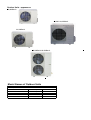
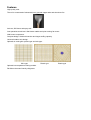
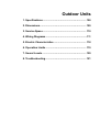
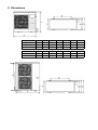
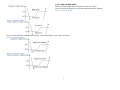
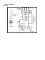
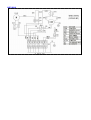
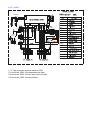
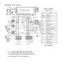
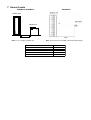
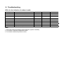
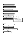
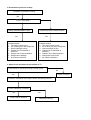
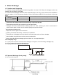
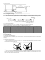
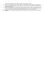
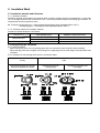
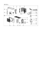
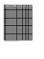
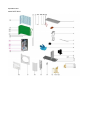
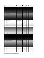
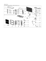
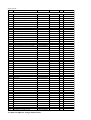
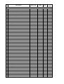
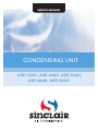
SERVICE MANUAL
CONDENSING UNIT
ASE-18AH, ASE-24AH, ASE-36AH,
ASE-48AH, ASE-60AH
Outdoor Units - appearance
18,000Btu/h
30,000~36,000Btu/h
24,000Btu/h
48,000Btu/h-60,000Btu/h
Model Names of Outdoor Units
Universal Outdoor unit Model
Heat Pump
ASE-18AH
ASE-24AH
ASE-36AH
ASE-48AH
ASE-60AH
Compressor type
Rotary
Rotary
SCROLL
SCROLL
SCROLL
Compressor Brand
GMCC
GMCC
SANYO
SANYO
SANYO
Features
High quality coils:
The coil is constructed of advanced inner grooved copper tube and aluminum fins.
Anti-rust, 500 hours salt spray test.
Low operation sound level: Well-known stable and quiet running fan motor.
Well-known compressor.
Compact design: Smaller dimension and larger stuffing capacity.
Universal outdoor unit design.
Optional air outlet grille: plastic type and wire type.
Wire type
Optional low temperature cooling module.
R410A environment friendly refrigerant.
Plastic type
Plastic type
Outdoor Units
1. Specifications ............................................................ 100
2. Dimensions ................................................................ 109
3. Service Space ............................................................ 110
4. Wiring Diagrams .........................................................111
5. Electric Characteristics ............................................. 118
6. Operation Limits ........................................................ 119
7. Sound Levels ............................................................. 120
8. Troubleshooting......................................................... 121
Model
Code
ASE-18AH
ASE-24AH
220037802190
220075301210
220~240-1-50
220~240-1-50
Power supply
V-ph-Hz
Max. input consumption
W
2950
3450
Max. input current
A
15
18
Model
PA225X2CS-4KU1
PA290X3CS-4MU1
Type
Rotary
Rotary
GMCC
GMCC
18493/18698
24498
2430
Brand
Compressor
Capacity
Btu/h
Input
W
Rated current(RLA)
A
1855/1940
8.7/8.7
Locked rotor Amp(LRA)
A
36.8
61
Capacitor
μF
Internal
50μF/440V-450V
Internal
50μF/440V-450V
Refrigerant oil
ml
ESTER OIL VG74 750
ESTER OIL VG74/950
YDK48-6H(A)
YDK100-6D
1
1
Thermal protector
Model
Qty
Outdoor fan
motor
Input
W
110
168.7
Capacitor
μF
3μF/450V
5μF/450V
Speed
r/min
890
900
Number of rows
Outdoor coil
2
2
Tube pitch(a)× row pitch(b)
mm
21x13.37
21x13.37
Fin spacing
mm
1.4
1.4
Tube outside dia.and type
mm
Coil length × height × width
mm
Hydrophilic aluminium
φ7, Inner grooved copper
tube
658x546x26.74
Hydrophilic aluminium
φ7, Inner grooved copper
tube
785x651x26.74
4
2439
4
3200
Fin type
Number of circuits
3
Outdoor air flow
m /h
Outdoor noise level (sound pressure)
Outdoor unit
Refrigerant
54
55
Dimension(W×H×D)
dB(A)
mm
760x590x285
845×695×324
Packing (W×H×D)
mm
887×645×355
965×755×395
Net/Gross weight
kg
39/42
53/57
R410a
R410a
1400
1900
Capillary
Capillary
Type
Charged volume
g
Throttle type
Design pressure
Refrigerant
piping
Ambient temp.
11.4
MPa
4.2/1.5
4.2/1.5
Liquid side/ Gas side
mm
φ6.4/φ12.7
φ9.5/φ15.9
Max. pipe length
m
25
25
Max. difference in level
m
15
15
℃
cooling:18~43;
heating:-7~24
cooling: 18~43;
heating:-7~24
Notes: 1. Nominal cooling capacities are based on the following conditions:
Indoor temp: 27°CDB, 19°CWB; Outdoor temp: 35°CDB;
2. Nominal heating capacities are based on the following conditions:
Indoor temp: 20°CDB; Outdoor temp: 7°CDB, 6°CWB;
3. Actual noise level may differ, depending on the room structure, etc, since these noise values are from an anechoic
room.
ASE-36AH
Model
Code
220075500682
Power supply
V-ph-Hz
Max. input consumption
W
4950
Max. input current
A
10
Model
C-SBN303H8D
Type
SCROLL
Brand
Compressor
SANYO
Capacity
Input
Rated current(RLA)
Btu/h
W
A
Locked rotor Amp(LRA)
A
Thermal protector
μF
--
Refrigerant oil
ml
FV68S/1700
W
μF
Speed
r/min
Fin type
Tube outside dia.and
type
Coil length × height ×
width
Number of circuits
Outdoor noise level (sound pressure)
Refrigerant
YDK190-6D
Qty
Input
Capacitor
Outdoor air flow
Outdoor unit
1
290
10μF/450V
840
2
mm
mm
mm
21x13.37
1.4
Hydrophilic aluminium
mm
φ7, Inner grooved copper tube
890x903x26.74
m3/h
7
5000
dB(A)
57
Dimension(W×H×D)
mm
990×966×354
Packing (W×H×D)
mm
1120×1100×435
Net/Gross weight
kg
92/96
Type
Charged volume
R410a
g
Throttle type
2900
capillary
Design pressure
Refrigerant
piping
48
Capacitor
Number of rows
Tube pitch(a)× row
pitch(b)
Fin spacing
Outdoor coil
33438
3650
6.58
Internal
Model
Outdoor fan
motor
380~415-3-50
MPa
4.2/1.5
Liquid side/ Gas side
mm
φ12.7/φ19
Max. pipe length
m
Max. difference in level
m
30
20
Ambient temp.
℃
cooling: 18~43; heating:-7~24
Notes: 1. Nominal cooling capacities are based on the following conditions:
Indoor temp: 27°CDB, 19°CWB; Outdoor temp: 35°CDB;
2. Nominal heating capacities are based on the following conditions:
Indoor temp: 20°CDB; Outdoor temp: 7°CDB, 6°CWB;
3. Actual noise level may differ, depending on the room structure, etc, since these noise values are from an anechoic
room.
Model
ASE-48AH
Code
220075701250
220075800650
380~415-3-50
380~415-3-50
W
6300
7500
A
10.5
12.6
Model
C-SBN373H8D
C-SBN453H8D
Type
Scroll
Scroll
Power supply
V-ph-Hz
Max. input consumption
Max. input current
Brand
Compressor
Sanyo
Sanyo
Capacity
Btu/h
48109
55956.8
Input
W
4750
5750
Rated current(RLA)
A
8.22
9.77
Locked rotor Amp(LRA)
A
66
67
Thermal protector
Capacitor
μF
Internal
--
Internal
---
Refrigerant oil
ml
FV68S,1700
FV68S, 1700
YDK65-6-1+YDK65-6F-1
YDK65-6+YDK65-6F
Model
Outdoor fan
motor
Outdoor coil
Qty
2
2
Input
W
171×2
148+140
Capacitor
μF
(4μF/450V)×2
(3.5μF/450V)×2
Speed
r/min
825
800
Number of rows
Tube pitch(a)× row
pitch(b)
Fin spacing
2
2
mm
21×13.37
22×19.05
mm
1.4
1.6
Fin type
Tube outside dia. and
type
Coil length × height ×
width
Hydrophilic aluminium
Hydrophilic aluminium
mm
φ7 Inner grooved copper tube
φ7.94 Inner grooved copper
tube
mm
840×1113×26.74
837×1100×38.1
4
6800
8
Number of circuits
3
Outdoor air flow
m /h
Outdoor noise level (sound pressure)
Outdoor unit
Refrigerant
dB(A)
6850
59
59
Dimension(W×H×D)
mm
900×1167×340
900×1167×340
Packing (W×H×D)
mm
1032×1307×443
1032×1307×443
Net/Gross weight
kg
102/106
106/111
R410a
R410A
3250
3200
Type
Charged volume
g
Throttle type
capillary
capillary
MPa
4.2/1.5
4.2/1.5
Liquid side/ Gas side
mm
φ12.7/φ19
φ12.7/φ19
Max. pipe length
m
50
50
Max. difference in level
m
25
25
Design pressure
Refrigerant
piping
ASE-60AH
Ambient temp.
℃
cooling: 18~43; heating:-7~24
cooling: 18~43; heating:-7~24
Notes: 1. Nominal cooling capacities are based on the following conditions:
Indoor temp: 27°CDB, 19°CWB; Outdoor temp: 35°CDB;
2. Nominal heating capacities are based on the following conditions:
Indoor temp: 20°CDB; Outdoor temp: 7°CDB, 6°CWB;
3. Actual noise level may differ, depending on the room structure, etc, since these noise values are from an anechoic
room.
Model
Rated current
ASE-18AH
ASE-24AH
ASE-36AH
ASE-48AH
ASE-60AH
15A
18A
10A 3 phases
12.5A 3 phases
12.6A 3 phases
2. Dimensions
H
Model (mm)
ASE-18AH
ASE-24AH
ASE-36AH
A
760
842
990
B
530
560
624
C
290
335
366
D
315
360
396
E
270
312
340
F
285
324
354
H
590
695
966
Model(mm)
ASE-48AH
ASE-60AH
A
900
900
B
590
590
C
378
378
D
400
400
E
330
330
F
340
340
H
1167
1167
Service Space
Obstacle
Air inlet
>30cm
Air inlet
>60cm
(Wall or obstacle)
>30cm
3.
Fix with bolt
Maintain channel
>200cm
>60cm
Air outlet
Necessary width
600mm is necessary between 2 outdoor units
Deep foundation
Logic of controlling compressor and fan of condensing units ASE-xxAH
1, For 18,24,36K units,
All the outdoor fan have a outdoor fan with fixed speed. Normally the outdoor fan runs with the compressor. The outdoor fan starts when the
compressor starts, and stops when the compressor stops. And their running status are determined by the difference between indoor and setting
temprature.
The control logic:
When in cooling mode,
1
2, For 48K and 60K units,
Some are with single fan and some are with twin fans,
For the units with single fan, the fan motors have two speeds; :
when in cooling mode,
When in heating mode,
For the units with two outdoor fan motors, in some occasions, one motor will stop:
When in cooling mode,
When in heating mode,
2
4. Wiring Diagrams
ASE-18AH
ASE-24AH
ASE-36AH
H-PRO K1
COMP
FAN3
CN201
CN100
T20 1
CN200
CAP3
S.V.
KM1
XT5
KM1
HEAT
XT4
S.V.
XT5-7
XT7
FAN3
H-PRO
T201
COMP
HEATER
CAP3
RT3
XS8-9
XT6
XP8-9
CN100-208
K1
1 2 3
XT4
N
4
RT4
XT3
XT3
T5
1, 2, 3 are just input signal to outdoor PCB
If 1 and N are 220V, the compressor will start.
If 2 and N are 220V, the four-way valve will start.
If 3 and N are 220V, the fan will start.
ASE-48AH A S E - 6 0 A H
1, 2, 3 are just input signal to outdoor PCB
If 1 and N are 220V, the compressor will start.
If 2 and N are 220V, the four-way valve will start.
If 3 and N are 220V, the fan will start.
5. Electric Characteristics
Model
Outdoor Unit
Hz
Voltage
Min.
Max.
ASE-18AH
50
220-240V
198V
254V
ASE-24AH
50
220-240V
198V
254V
ASE-36AH
50
380-415V
342V
418V
ASE-48AH
50
380-415V
342V
418V
ASE-60AH
50
380-415V
342V
418V
6. Operation Limits
Operation mode
Outdoor temperature(℃)
Room temperature(℃)
Cooling operation
18~43
17~30
Heating operation
-7~24
17~30
Cooling & Heating
Cooling & Heating
Heating
Cooling
25
20
40
35
Outdoor temperature(℃ WB)
Outdoor temperature(℃ DB)
45
STD
30
25
20
15
10
15
20
25
30
Indoor temperature(℃ WB)
35
15
STD
10
5
0
-5
-10
10
15
20
25
30
Indoor temperature(℃ DB)
35
7. Sound Levels
18000Btu/h-48000Btu/h
60000Btu/h
Outdoor Unit
Microphone
H
1.0m
Note: H= 0.5 × height of outdoor unit
Model
ASE-18AH
ASE-24AH
ASE-36AH (3 phase)
ASE-48AH
ASE-60AH
Note: The point A is in the middle of the whole outdoor panel.
Noise level dB(A)
54
55
57
59
59
8. Troubleshooting
LEDs’ for the indication of outdoor trouble
Type
Contents
LED1
LED2
LED3
Trouble
Phase sequence
Flash
Off
Off
Trouble
Lack of phase(A,B)
Flash
Off
Off
Trouble
Lack of phase(C)
Off
Off
Off
Trouble
Protection of Low pressure
Flash
Flash
Off
Trouble
Overload of current
Off
Off
Flash
Trouble
Communication malfunction
Flash
Off
Flash
Trouble
Open-circuit and short-circuit trouble of T3
Off
Flash
Flash
Trouble
Open-circuit and short-circuit trouble of T4
Off
Flash
Off
Trouble
High temperature protection of condenser
Flash
Flash
Flash
Note:
1. If the LED1-LED3 are flashing slowly,means the system is stand-by.
2. T3: Outdoor condenser temperature sensor
3. T4: Outdoor ambient temperature sensor
a. Phase sequence error:
Phase sequence error
Change the order of two of the wires to power supply.
Switch on the unit again.
If the problem can not be solved, the outdoor PCB is defective
b. Overload of current
Overload of current
Check the current, normally
Is the current in rated range?
No
Yes
The outdoor PCB is defective
Possible reason
1. Outdoor fan is defective
2. The compressor is defective
3. Refrigerant is over charged
4. Air enter the refrigerant system
5. Heat exchanger is too dirty
c. Lack of phase
Lack of phase
Check the power supply, is it 3 phase,
380-415V?
Yes
Check the connection between power supply and terminal,
is the voltage in outdoor terminal is 3 phase, 380-415V?
Yes
Outdoor PCB is defective
d. Protection of pressure or temp.
Protection of pressure or temp.
Yes
Is it k1 or K2 open ?
Is temp. protective switch K1 open
Is pressure protective switch K2 open
Yes
Possible reason
1. The wires is loose to K1
2. Air or other gas in the refrigerant.
3. Heat exchanger is dirty
4. Outdoor fan or fan blade is
defective
5. Outdoor unit is bad ventilation
6. Refrigerant is leakage
7. K1 switch is defective
Yes
Possible reason
1. The wires is loose to K2
2. Air or other gas in the refrigerant.
3. Heat exchanger is dirty
4. Outdoor fan or fan blade is
defective
5. Outdoor unit is bad ventilation
6. Refrigerant is two much
7. K2 switch is defective
e. Open-circuit and short-circuit trouble of T3
Is connection to connector of temp. sensor good?
Repair connector
Yes
Check the resistance of the temp. sensor according to Annex 1
Is it the resistance is normal?
Yes
Indoor PCB is defective.
No
No
Replace the sensor
f. Open-circuit and short-circuit trouble of T4
Is connection to connector of temp. sensor good?
No
Yes
Check the resistance of the temp. sensor according to Annex 1
Repair connector
Is it the resistance is normal?
No
Yes
Indoor PCB is defective.
Replace the sensor
g. High temperature protection of condenser
High temperature protection of condenser
Check the resistance of the temp. sensor
according to Annex 1, is it normal?
Yes
Possible reason
1. Air or other gas in the refrigerant.
2. Heat exchanger is dirty
3. Outdoor fan or fan blade is
defective
4. Outdoor unit is bad ventilation
5. Refrigerant is leakage
6. Outdoor PCB is defective
No
Replace the sensor
9. Q&A
(1) What is the value of evaporation temperature which is used for calculate cooling capacity?
The evaporation temperature for all of indoor units is around 9-12°C, tested in standard cooling conditions.
Installation
1.Precaution on Installation .............................................. 132
2.Vacuum Dry and Leakage Checking.............................. 133
3.Additional Refrigerant Charge ....................................... 135
4.Water Drainage ............................................................. 136
5.Insulation Work ............................................................. 139
6.Wiring ........................................................................... 140
7.Test Operation .............................................................. 141
1. Precaution on Installation
1). Measure the necessary length of the connecting pipe, and make it by the following way.
a.
Connect the indoor unit at first, then the outdoor unit.
Bend the tubing in proper way. Do not harm them.
Specially Notice the pipe length/height/dimension of each capacity.
Maximum pipe length
Model
12,000Btu/h
18,000Btu/h ~30,000Btu/h
36,000Btu/h
48,000Btu/h~60,000Btu/h
Piping sizes
Model
12,000Btu/h~18,000Btu/h
24,000Btu/h
30,000Btu/h~60,000Btu/h(Cooling
Only)
30,000Btu/h~60,000Btu/h(Cooling
Heating)
Max. Length
15m
25m
30m
50m
&
Max. Elevation
8m
15m
20m
25m
Liquid(mm)
6.4
Gas(mm)
12.7
9.5
15.9
9.5
15.9
12.7
19
CAUTIONS
l Daub the surfaces of the flare pipe and the joint nuts with frozen oil, and wrench it for 3~4 rounds
l With hands before fasten the flare nuts.
l Be sure to use two wrenches simultaneously when you connect or disconnect the pipes.
Flare dimension A
Pipe gauge
Tightening torque
Flare shape
Min (mm) Max
15~16N.m
Φ6.4
8.3
8.7
(153~163 kgf.cm)
25~26N.m
Φ9.5
12.0
12.4
(255~265kgf.cm)
35~36N.m
Φ12.7
15.4
15.8
(357~367kgf.cm)
45~47N.m
18.6
19.1
Φ15.9
(459~480 kgf.cm)
65~67N.m
Φ19.1
22.9
23.3
(663~684kgf.cm)
b. The stop value of the outdoor unit should be closed absolutely (as original state). Every time you
connect it, first loosen the nuts at the part of stop value, then connect the flare pipe immediately (in 5
minutes). If the nuts have been loosened for a long time, dusts and other impurities may enter the pipe
system and may cause malfunction later. So please expel the air out of the pipe with refrigerant before
connection.
c.
2)
a.
b.
Expel the air after connecting the refrigerant pipe with the indoor unit and the outdoor unit. Then fasten
the nuts at the repair-points.
Locate The Pipe
Drill a hole in the wall (suitable just for the size of the wall conduit), then set on the fittings such as the
wall conduit and its cover.
Bind the connecting pipe and the cables together tightly with binding tapes. Do not let air in, which will
cause water leakage by condensation.
c.
Pass the bound connecting pipe through the wall conduit from outside. Be careful of the pipe allocation
to do no damage to the tubing.
3)
Connect the pipes.
4)
Then, open the stem of stop values of the outdoor unit to make the refrigerant pipe connecting the
indoor unit with the outdoor unit in fluent flow.
5)
Be sure of no leakage by checking it with leak detector or soap water.
6)
Cover the joint of the connecting pipe to the indoor unit with the soundproof / insulating sheath (fittings),
and bind it well with the tapes to prevent leakage.
2. Vacuum Dry and Leakage Checking
2.1 Vacuum Dry: use vacuum pump to change the moisture (liquid) into steam (gas) in the pipe and
discharge it out of the pipe to make the pipe dry. Under one atmospheric pressure, the boiling point of
water(steam temperature) is 100℃. Use vacuum pump to make the pressure in the pipe near vacuum
state, the boiling point of water falls relatively. When it falls under outdoor temperature, the moisture in
the pipe will be vaporized.
2.2 Vacuum dry procedure
There are two methods of vacuum dry due to different construction environment: common vacuum dry,
special vacuum dry.
①. Common vacuum dry procedure
l Vacuum dry (for the first time)---connect the all-purpose detector to the inlet of liquid pipe and gas pipe,
and run the vacuum pump more than two hours (the vacuum pump should be below -755mmHg)
l If the pump can’t achieve below -755mmHg after pumping 2 hours, moisture or leakage point will still
exist in the pipe. At this time, it should be pumped 1 hour more.
l If the pump can’t achieve -755mmHg after pumping 3 hours, please check if there are some leakage
points.
l Vacuum placement test: place 1 hour when it achieves -755mmHg, pass if the vacuum watch shows no
rising. If it rises, it shows there’s moisture or leakage point.
l Vacuuming from liquid pipe and gas pipe at the same time.
l Sketch map of common vacuum dry procedure.
②. Special vacuum dry procedure
l This vacuum dry method is used in the following conditions:
l There’s moisture when flushing the refrigerant pipe.
l Rainwater may enter into the pipe.
l Vacuum dry for the first time ······ 2h pumping
③. Vacuum destroy for the second time ······ Fill nitrogen to 0.5Kgf/cm 2
Because nitrogen is for drying gas, it has vacuum drying effect during vacuum destroy. But if the moisture is
too much, this method can’t dry thoroughly. So, please pay more attention to prevent water entering and
forming condensation water.
④. Vacuum
dry for the second time······1h pumping
Determinant: Pass if achieving below -755mmHg. If -755mmHg can’t be achieved in 2h, repeat procedure ③
and ④.
⑤.
Vacuum placing test ······ 1h
⑥. Sketch map of special vacuum dry procedure
3. Additional Refrigerant Charge
Caution
● Refrigerant cannot be charged until field wiring has been completed.
● Refrigerant may only be charged after performing the leak test and the vacuum pumping.
● When charging a system, care shall be taken that its maximum permissible charge is never exceeded, in
view of the danger of liquid hammer.
● Charging with an unsuitable substance may cause explosions and accidents, so always ensure that the
appropriate refrigerant is charged.
● Refrigerant containers shall be opened slowly.
● Always use protective gloves and protect your eyes when charging refrigerant.
The outdoor unit is factory charged with refrigerant. Calculate the added refrigerant according to the
diameter and the length of the liquid side pipe of the outdoor unit/indoor unit
R(g)
L(m)
D(mm)
φ6.4
Less than 5m (One-way)
—
Added Refrigerant When
11g/m×(L-5)
Over 5m(One-way)
Remark:
R (g): Additional refrigerant to be charged
L (m): The length of the refrigerant pipe (one-way)
D (mm): Liquid side piping diameter
Φ9.5
Φ12.7
—
—
30g/m×(L-5)
60g/m×(L-5)
4. Water Drainage
4.1 Gradient and Supporting
4.1.1 Keep the drainpipe sloping downwards at a gradient of at least 1/100. Keep the drainpipe as short as
possible and eliminate the air bubble.
4.1.2 The horizontal drainpipe should be short. When the pipe is too long, a prop stand must be installed to
keep the gradient of 1/100 and prevent bending. Refer to the following table for the specification of the prop
stand.
Hard PVC pipe
Diameter
Distance between the prop stands
25~40mm
1.5~2m
4.1.3. Precautions
① The diameter of drainpipe should meet the drainage requirement at least.
② The drainpipe should be heat-insulated to prevent atomization.
③ Drainpipe should be installed before installing indoor unit. After powering on, there is some water in
water-receiver plate. Please check if the drain pump can operate correctly.
④ All connection should be firm.
⑤ Wipe color on PVC pipe to note connection.
⑥ Climbing, horizontal and bending conditions are prohibited.
⑦ The dimension of drainpipe can’t less than the connecting dimension of indoor drainpipe.
⑧ Heat-insulation should be done well to prevent condensation.
⑨ Indoor units with different drainage type can’t share one convergent drainpipe.
4.2 Drainpipe Trap
4.2.1. If the pressure at the connection of the drainpipe is negative, it needs to design drainpipe trap.
4.2.2. Every indoor unit needs one drainpipe trap.
4.2.3. A plug should be designed to do cleaning.
4.3 Upwards drainage (drain pump)
For Four-way cassette(compact)
50cm 50cm
Plug
For Four-way cassette
4.4 Convergent drainage
4.4.1. The number of indoor units should be as small as possible to prevent the traverse main pipe overlong.
4.4.2. Indoor unit with drain pump and indoor unit without drain pump should be in different drainage system.
4.4.3. Selecting the diameter
Number of connecting indoor units→Calculate drainage volume→Select the diameter
Calculate allowed volume =Total cooling capacity of indoor units(HP)×2 (l/ hr)
Allowed volume(lean 1/50) (l/ hr)
I.D. (mm)
集中排水管
Hard PVC
∽≤14
¢25
Hard PVC
14<∽≤88
¢30
Hard PVC
88<∽≤334
¢40
Hard PVC
175<∽≤334
¢50
Hard PVC
334<∽
¢80
Thick
3.0
3.5
4.0
4.5
6.0
4.5 Drainage test
4.5.1Drainage without drain pump
After finishing drainpipe installation, pour some water into the water receiver plate to check if the water flows
smoothly.
4.5.2 Drainage with drain pump
① Poke the Water Level Switch, remove the cover, use water pipe to pour 2000ml water into the water
receipt plate through the water inlet.
② Turn on the power to Cooling operation. Check the pump’s operation and switch on the Water Level
Switch. Check the pump’s sound and look into the transparent hard pipe in the outlet at the same time to
check if the water can discharge normally.
③ Stop the air conditioner running, turn off the power, and put back the cover.
Stop the air conditioner. After 3 minutes, check if it has abnormity. If the collocation of drainpipes is
illogical, the water will flow back overfull, which will cause the alarm lamp flashes, even overflow from
the water receipt plate.
l Keep on pouring water until it gives an alarm signal for high water level, check if the pump drains water
at once. If the water level can’t fall below the alarmed water level after 3 minutes, the air conditioner will
stop. Turn off the power and drain the remained water, and then turn on the air conditioner.
Note: the drain stuff in the main water receipt plate is for maintenance. Stuff up the drain stuff to prevent water
leakage.
l
5. Insulation Work
5.1 Insulation material and thickness
5.1.1. Insulation material
Insulation material should adopt the material which is able to endure the pipe’s temperature: no less than
70℃ in the high-pressure side, no less than 120℃ in the low-pressure side(For the cooling type machine, no
requirements at the low-pressure side.)
u
Example: Heat pump type----Heat-resistant Polyethylene foam (withstand above 120℃)
Cooling only type----Polyethylene foam (withstand above 100℃)
5.1.2. Thickness choice for insulation material
Insulation material thickness is as follows:
Refrigerant pipe
Drainage pipe
Pipe diameter (mm)
Φ6.4—Φ25.4
Φ28.6—Φ38.1
Inner diameterΦ20—Φ32
Adiabatic material thickness
10mm
15mm
6mm
5.2 Refrigerant pipe insulation
5.2.1. Work Procedure
① Before laying the pipes, the non-jointing parts and non-connection parts should be heat insulated.
② When the gas proof test is eligible, the jointing area, expanding area and the flange area should be heat
insulated
5.2.2. Insulation for non-jointing parts and non-connection parts
wrong
Gas pipe and liquid pipe should
not be put together to insulate
right
Insulate the gas pipe
(cooling only)
Insulate the gas pipe and
liquid pipe
For construction convenience, before laying pipes, use insulation material to insulate the pipes to be deal
with, at the same time, at two ends of the pipe, remain some length not to be insulated, in order to be welded
and check the leakage after laying the pipes.
5.2.3. Insulate for the jointing area, expanding area and the flange area
① Insulate for the jointing area, expanding area and the flange area should be done after checking leakage
of the pipes
② Make sure there’s no clearance in the joining part of the accessorial insulation material and local
preparative insulation material.
5.3 Drainage pipe insulation
The connection part should be insulated, or else water will be condensing at the non-insulation part.
5.4 Note
5.4.1 The jointing area, expanding area and the flange area should be heat insulated after passing the
pressure test
5.4.2 The gas and liquid pipe should be heat insulated individually, the connecting part should be heat
insulated individually.
5.4.3 Use the attached heat-insulation material to insulate the pipe connections (pipes’ tie-in ,expand nut ) of
the indoor unit
6. Wiring
Please refer to the Wiring Diagram.
7. Test Operation
(1) The test operation must be carried out after the entire installation has been completed.
(2) Please confirm the following points before the test operation.
l The indoor unit and outdoor unit are installed properly.
l Tubing and wiring are correctly completed.
l The refrigerant pipe system is leakage-checked.
l The drainage is unimpeded.
l The ground wiring is connected correctly.
l The length of the tubing and the added stow capacity of the refrigerant have been recorded.
l The power voltage fits the rated voltage of the air conditioner.
l There is no obstacle at the outlet and inlet of the outdoor and indoor units.
l The gas-side and liquid-side stop values are both opened.
l The air conditioner is pre-heated by turning on the power.
(3) According to the user's requirement, install the remote controller when the remote controller's
signal can reach the indoor unit smoothly.
(4) Test operation
Set the air conditioner under the mode of "COOLING" with the remote controller, and check the following
points.
Indoor unit
l Whether the switch on the remote controller works well.
l Whether the buttons on the remote controller works well.
l Whether the air flow louver moves normally.
l Whether the room temperature is adjusted well.
l Whether the indicator lights normally.
l Whether the temporary buttons works well.
l Whether the drainage is normal.
l Whether there is vibration or abnormal noise during operation.
Outdoor unit
l Whether there is vibration or abnormal noise during operation.
l Whether the generated wind, noise, or condensed of by the air conditioner have influenced your
neighborhood.
l Whether any of the refrigerant is leaked.
PARTS GUIDE
CONDENSING UNIT
ASE-18AH, ASE-24AH, ASE-36AH,
ASE-48AH, ASE-60AH
Exploded view
model: ASE-18AH
Spare part list
No
Description
Part Code
MODEL: ASE-18AH
1
2
3
4
8
9
10
11
12
13
14
15
16
17
18
20
20.1
20.2
20.3
20.4
20.5
20.6
21
22
22.1
22.2
23
23.1
23.2
24
25
26
26
29
30
Top cover assembly
Supporter assembly of fan motor
Condenser assembly
Rear net
Chassis assembly
Big handle
Water collector
Right clapboard assembly
Valve plate
Partition board assembly
Front panel assembly
Air outlet grille
Asynchronous motor
Axial flow fan
Left supporter bar
Electronic control box assembly
Fan motor capacitor
Compressor capacitor
Wire joint
Wire joint,2p
Installation plate of electric parts
Capacitor clip
Pipe temperature sensor assembly
Liquid valve assembly
Liquid valve
One way valve
4-way valve assembly
Gas valve
4-way valve
Compressor wire assembly
Compressor
Nut
Nut
Small handle
Clamp of front net
201237400324
201237890017
201537990033
2011374G0003
201237890085
201148100010
201137400000
201248100239
201237200044
201237890019
201237890067
201237890069
202400410505
201100300514
201237400323
203337890230
202401100353
202401090057
202301450130
202301450043
201275290102
201200100002
202440500004
201637890680
201600740523
201600800065
201637890605
201600720195
201600690011
202402220011
201400620240
201600330003
201600330001
201157090002
201135110801
The data are subject to change without notice.
Note
Qty Price Code
1
1
1
1
1
1
1
1
1
1
1
1
1
1
1
1
1
1
1
1
1
1
1
1
1
1
1
1
1
1
1
1
8
Exploded view
model:ASE-24AH
Spare part list
No
Description
Part Code
MODEL: ASE-24AH
Note
Qty
1
Top cover assembly
201248100266
1
2
Fan motor fixing foam
202245500001
1
3
Supporter assembly of fan motor
2012481G0038
1
4
Rear net frame
201248100076
1
5
Asynchronous motor
202400430109
1
6
Axial flow fan
201145500002
1
7
Compressor
201400620150
1
8
Partition board assembly
201238090056
1
9
Water collector
201137390007
1
10
Valve plate
201237300021
1
11
Chassis assembly
201248100235
1
12
Liquid valve assembly
201675390577
1
12.1 Filter
201637990265
1
12.2 One way valve
201600800014
1
12.3 Liquid valve
201600740299
1
201675390574
1
13.2 Gas valve
201600720296
1
13.3 4-way valve
13
4-way valve assembly
201600690011
1
14
Big handle assembly
201148100010
1
15
Rear right clapboard assembly
201237890063
1
16
Front right clapboard assembly
201248100234
1
17
Front panel
201248100236
1
18
Air outlet grille
201237890022
1
19
Small handle
201157090002
1
20
Electronic control box assembly
203375390286
1
20.2 Wire joint
202301450122
1
20.2 Wire joint
202301450127
1
20.3 Compressor capacitor
202401090057
1
20.4 Installation plate of electric parts
201237900010
1
20.5 Fan motor capacitor
202401100505
1
22
Clamp of front net
201135110801
8
23
Pipe temperature sensor assembly
202440500004
1
24
Condenser assembly
201537990000
1
24.1 Fluted pipe assembly
201635490563
1
24.2 Input pipe assembly
201637990115
1
24.3 Condenser assembly
201535490089
1
25
Rear net
2011481G0001
1
26
Left supporter
201248100228
1
27
Copper nut
201600320001
1
27
Copper nut
201600320003
1
28
Sphere pad
201119900804
1
28
Sphere pad
201119900802
1
29
Compressor wire assembly
202402220094
1
The data are subject to change without notice.
Price Code
Exploded view
model:ASE-36AH
Spare part list
No
1
2
3
4
5
6
7
8
9
10
11
11.1
11.2
12
12.1
13
14
15
16
16.3
17
17
18
18
19
20
21
22
24
25
26
27
28
29
30
30.1
30.1
30.1
30.2
30.3
30.4
30.5
30.6
30.7
31
32
33
Description
Part Code
MODEL: ASE-36AH
Top cover assembly
Rear supporter
Supporter assembly of fan motor
Fix clamp of segregator
Accumulator cylinder
Asynchronous motor
Suction pipe
Condenser assembly
Rear right clapboard assembly
Front right clapboard assembly
4-way valve assembly
Gas valve
4-way valve
Liquid valve assembly
Liquid valve
Valve plate
Chassis
Compressor
Discharge pipe assembly
Pressure switch
Copper nut
Copper nut
Sphere pad
Sphere pad
Compressor wire assembly
Crankcase electric heater
Pipe temperature sensor assembly
Discharge temperature sensor
Front panel
Front net assembly
Axial flow fan
Partition board assembly
Rear net
Left supporter
Electronic control box assembly
Wire joint
Wire joint
Wire joint
Installation plate of electric parts
AC contactor
Terminal board
Main control board assembly
Compressor capacitor
Transformer
Water collector
Big handle assembly
Indoor temperature sensor assembly
201248700174
2012487G0011
201275590200
201245000901
201601000193
202400400582
201648700055
201575590104
201248700171
201248700056
201675590621
201600720684
201600600124
201675591069
201600740704
201248790011
201248700168
201400710580
201675591023
202301820020
201600320004
201600320002
201119900803
201119900801
202447590004
202447090021
202301300111
202301610024
201248700072
201248700055
201100300145
201248700070
2011487G0001
201248700172
203375590218
202301450117
202301450130
202301450039
201275590077
202300850046
201247010643
201375590150
202401000006
202300900083
201148790000
201157390007
202301300196
The data are subject to change without notice.
Note
Qty Price Code
1
1
1
1
1
1
1
1
1
1
1
1
1
1
1
1
1
1
1
1
1
1
1
1
1
1
1
1
1
1
1
1
1
1
1
3
1
1
1
1
1
1
1
1
1
1
1
Exploded view
model:ASE-48AH, ASE-60AH (=ASF-60A outdoor unit)
Spare part list
No
Description
Part Code
MODEL: ASE-48AH
1
2
3
4
4
5
6
7
8
9
10
11
12
13
14
14
15
17
18
19
20
21
22
23
24
24
25
25
26
26.1
26.2
26.3
26.4
26.5
26.5
26.5
26.6
27
28
29
30
30.1
31
33
33.1
34
34.1
35
35.1
35.2
37
Top cover assembly
Axial flow fan
Rear-left supporting board
Asynchronous motor YDK65-6(B)
Asynchronous motor YDK65-6F(B)
Supporter assembly of fan motor
Front net assembly
Clamp of front net
Front panel
Partition board assembly
Front-right panel assembly
Rear-right panel
Rear supporter
Indoor temperature sensor assembly
Condenser assembly
Condenser assembly
Pipe temperature sensor assembly
Chassis
Rear net
Separator
Big handle assembly
Handle
Water collector
Valve plate
Copper nut
Copper nut
Sphere pad
Sphere pad
Electronic control box assembly
Installation plate of electric parts
Main control board assembly
AC contactor
Transformer
Wire joint
Wire joint
Wire joint
Fan motor capacitor
Compressor
Compressor wire assembly
Crankcase electric heater
Discharge pipe assembly
Pressure switch
Discharge temperature sensor
Suction pipe assembly
Pressure switch
Liquid valve assembly
High pressure valve
Gas valve assembly
4-way valve
Gas valve
Condenser connection pipe
201275600087
201100300102
201275600107
202400401180
202400401181
201275600101
201275890056
201135110801
201275600105
201275890038
201275890054
201275600103
201275600086
202301300196
201575790067
201575790069
202301300111
201275600100
201175600083
201601100059
201157390007
201148700009
201148790000
201248790011
201600320004
201600320002
201119900801
201119900803
203375790082
201275600111
201375490007
202300850045
202300900153
202301450003
202301450039
202301450117
202401100354
201400710570
202445400405
202403100238
2016757A0102
202301820042
202301610500
2016757A0105
202301820021
201675790499
201600740519
201675790495
201600600124
201600720684
201675790492
The data are subject to change without notice.
Note
Qty
1
2
1
1
1
1
2
8
1
1
1
1
1
1
1
1
1
1
1
1
1
2
1
1
1
1
1
1
1
1
1
1
1
1
1
3
2
1
1
1
1
1
1
1
1
1
1
1
1
1
1
Price Code
No
Description
Part Code
Note
Qty
MODEL: ASE-60AH (=ASF-60A outdoor)
1
2
3
4
4
5
6
7
8
9
10
11
12
13
14
15
17
18
19
20
21
22
23
24
24
25
25
26
26.1
26.2
26.3
26.4
26.5
26.5
26.5
26.6
27
28
29
30
30.1
31
33
33.1
34
34.1
35
35.1
35.2
Top cover assembly
Axial flow fan
Rear-left supporting board
Asynchronous motor YDK65-6(B)
Asynchronous motor YDK65-6F(B)
Supporter assembly of fan motor
Front net assembly
Clamp of front net
Front panel
Partition board assembly
Front-right panel assembly
Rear-right panel
Rear supporter
Indoor temperature sensor assembly
Condenser assembly
Pipe temperature sensor assembly
Chassis
Rear net
Separator
Big handle assembly
Handle
Water collector
Valve plate
Copper nut
Copper nut
Sphere pad
Sphere pad
Electronic control box assembly
Installation plate of electric parts
Main control board assembly
AC contactor
Transformer
Wire joint
Wire joint
Wire joint
Fan motor capacitor
Compressor
Compressor wire assembly
Crankcase electric heater
Discharge pipe assembly
Pressure switch
Discharge temperature sensor
Suction pipe assembly
Pressure switch
Liquid valve assembly
Liquid valve
Gas valve assembly
4-way valve
Gas valve
The data are subject to change without notice.
201275600087
201100300102
201275600107
202400401180
202400401181
201275600101
201275890056
201135110801
201275600105
201275890038
201275890054
201275600089
201275600086
202301300196
201548890010
202301300111
201275600100
201175600083
201601100059
201157390007
201148700009
201148790000
201248790011
201600320004
201600320002
201119900801
201119900803
203375890114
201275600111
201375890088
202300850045
202300900153
202301450003
202301450039
202301450117
202401100354
201400710560
202445400405
202447090021
201675890375
2023018A0011
202301610500
201675890378
202301810104
201675890373
201600740599
201675890721
201600600124
201600720684
1
2
1
1
1
1
2
8
1
1
1
1
1
1
1
1
1
1
1
1
2
1
1
1
1
1
1
1
1
1
1
1
1
1
3
2
1
1
1
1
1
1
1
1
1
1
1
1
1
Price
Code