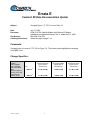
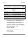
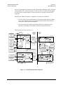
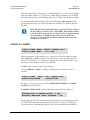
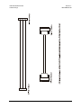
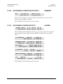
Download Comtech EF Data KST-2000B Product specifications

Transcript
CDM-600
Open Network Satellite Modem (2.4 kbps – 20 Mbps)
Installation and Operation Manual
For Firmware Version 2.0.1 or higher
(see New in this Release – Section 1.5)
IMPORTANT NOTE: The information contained in this document supercedes all previously published
information regarding this product. Product specifications are subject to change without prior notice.
Part Number MN/CDM600.IOM
Revision 7
CDM-600
Open Network Satellite Modem Manual
Addendum A
Subject: Update for new Drop and Insert capability
Part Number: MN/CDM600.AA7
Revision 7 Addendum A
October 10, 2005
Special Instructions:
This document contains changes and new information for the CDM-600 Open Network Satellite
Modem manual, part number MN/CDM600.IOM Rev. 7 dated February 9, 2005.
Comtech EF Data is an ISO 9001 Registered Company
Copyright © Comtech EF Data Corporation, 2003,2004,2005.
All rights reserved.
Printed in the USA.
th
Comtech EF Data Corporation, 2114 W. 7 Street, Tempe, Arizona 85281 USA, (480) 333-2200, FAX: (480) 333-2161.
New Features/Changes
•
Changes to Drop and Insert
Since Version 7 of the CDM-600 Manual was published, there has been engineering
development to modify the E1 Drop and Insert feature to add high-rate ESC (Engineering
Service Channel) and AUPC (Automatic Uplink Power Control).
•
New remote control commands
Two new commands have been added to query the Tx and Rx symbol rates. These are TSR?
and RSR? respectively (query-only). This information was already displayed on the front panel,
but had not been available via the remote port.
A front panel lockout feature has been added. Already, when in remote mode, user access of the
front panel of the modem allows viewing of the configuration parameters, but does not allow
changes to the configuration parameters. To make changes via the front panel, the user must
first configure the modem for Local control via the Remote menu. This front panel lockout
(FPL) feature, when activated, prevents or locks-out that ability to configure the modem into
local mode from the front panel.
Refer to the remote control command table, following, for more detail.
6.1 Description of D&I with ESC and AUPC
The Drop and Insert (D&I) framing has been extended with the release of firmware version
2.1.0 to include the capability of adding high-rate ESC (Engineering Service Channel) and
AUPC (Automatic Uplink Power Control). Currently this is available for E1 operation
only. Refer to the manual for details of each of these features
The high-rate ESC channel operates the same for D&I as it does for IBS framing, using
bytes 16 and 48 of the overhead channel, as well as half of byte 32, to pass the data
characters over the satellite link. Because these bits are reserved for signaling, this new
feature is not available for E1-CAS mode. The AUPC portion (which is not available
with IBS framing) occupies the unused first bit of the unique word (byte 0).
To enable Drop and Insert with ESC and AUPC, the correct sequence of configuration
must be followed. This applies when configuring via the front panel, or when using
individual remote control commands. Prior to this new firmware version 2.1.0, neither
ESC nor AUPC could be combined with D&I.
Configuration sequence:
1
2
3
4
Parameter
Mode:
D&I type:
ESC
Power level mode:
Setting
D&I
E1-CCS
On
AUPC
Detailed in
section
6.3.1.2 (requires D&I FAST option)
6.3.1.6
6.3.1.8
6.3.1.3
The available ESC baud rates for D&I depend on Tx and Rx datarate. They are the same
as those for high-rate IBS ESC. Pin-out information for the Overhead Interface
Connector which carries the ESC channel is shown in section 5.3.
The maximum ESC baud rate is limited by the lower of the Tx or Rx data rates. If a data
rate is edited so that a baud rate is no longer available, the baud rate will automatically be
reduced to the next permitted value. The data-rate breakpoints are:
Data rate
64 kbps
> = 128 kbps
> = 256 kbps
> = 384 kbps
> = 512 kbps
> = 768 kbps
> =1280 kbps
Max ESC baud rate
2400
4800
9600
14400
19200
28800
38400
(Note: breakpoint change)
Note: For AUPC to be effective, it must be enabled on both the local & remote modems.
1
N/A
N/A
FPL=
Rx Symbol
Rate
Front Panel
Lockout
Command
(Instruction
Code and
Qualifier)
Tx Symbol
Rate
Parameter
Type
1 byte,
numeric
9 bytes,
numeric
9 bytes,
numeric
Arguments
for Command
or Response
to Query
2
Disable the lockout by either FPL=0, or by setting into local
mode using LRS=0.
Format is ddddd.ddd
Command or query.
Control the state of front-panel lockout, where:
0 = no lockout
1 = front panel lockout active.
Format is ddddd.ddd
Query only.
This command allows remote access to the Rx symbol rate.
This value is shown on the front panel.
Query only.
This command allows remote access to the Tx symbol rate.
This value is shown on the front panel.
Description of Arguments
FPL=
FPL?
FPL*
FPL#
RSR?
RSR=
TSR?
TSR=
Response to
Command
FPL?
RSR?
TSR?
Query
(Instruction
Code and
Qualifier)
FPL=x
(see description of
arguments)
RSR=ddddd.ddd
(see description of
arguments)
TSR=ddddd.ddd
(see description of
arguments)
Response to Query
MN/CDM600.AA7
Addendum B
Subject:
Replacement of Appendix A. CABLE DRAWINGS
Date:
October 13, 2008
Original Manual Part
Number/Rev:
MN/CDM600.IOM
Rev 7
Addendum Number /
Agile Document ID:
AD-CDM600-AB7
Agile CO Number
CO5356
Notes:
1. Insert this title page immediately after the manual title page to indicate that the manual was
updated with this addendum.
2. To identify changes made to the previous edition, refer to the change bars located in the outside
margins. [or:] Change bars were not utilized.
AGILE DOC ID AD-CDM600-AB7 THIS DOCUMENT IS NOT SUBJECT TO REVISION/UPDATE!
1
AGILE CO5356
Change Specifics:
This information will be incorporated into the next revision.
Collating Instructions
To update the manual, remove and insert the pages as follows:
Remove
Insert
Appendix A (pages A-1 through A-4)
Appendix A (pages A-1 through A-6)
AGILE DOC ID AD-CDM600-AB7 THIS DOCUMENT IS NOT SUBJECT TO REVISION/UPDATE!
2
AGILE CO5356
Appendix A. CABLE DRAWINGS
A.1
Introduction
The EIA-530 standard pinout provided on the CDM-600 is becoming more popular in many applications. However, there are
still occasions, particularly with existing EIA-422/449 and V.35 users, when a conversion must be made.
For situations where such conversions are required, refer to the following table to select the appropriate cable.
In addition, the standard EIA-232 cable used for performing Flash Upgrading is depicted. This cable connects the CDM-600 Remote
Control Port to the serial communications port of an external PC.
App. A FIG
CEFD CABLE P/N
DESCRIPTION
A-1
CA/WR0049
A-2
CA/WR0059-2
Modem Conversion Cable:
EIA-530 Æ V.35 Winchester DCE Conversion (DB-25M Æ Winchester 34-pin Female, 8’)
A-3
CA/WR9718-1
Modem Conversion Cable:
CDM Æ EIA-530 Conversion (DB-25M Æ DB-25F, 8’)
A-4
N/A
Modem Conversion Cable:
EIA-530 Æ V.35 Winchester DCE Conversion (DB-25M Æ Winchester 34-pin Female)
A-5
N/A
EIA-232 Switch Programming Cable (for Flash upgrading):
CDM-600 Remote Port Æ PC Serial Port (DB-9F Æ DB-9F)
Modem Conversion Cable:
EIA-530 Æ RS-422/449 DCE Conversion (DB-25M ÆDB-25F, 40”)
A-1
CDM-600 Satellite Modem
Cable Drawings
MN/CDM600.IOM Revision 7
AD-CDM600-AB7
A.1.1 EIA-530 to RS-422/449 Data Cable
Figure A-1 shows the cable drawing for EIA-530 to RS-422/449 DCE conversion for connections between the CDM-600 and the User data.
Figure A-1. DCE Conversion Cable: EIA-530 to RS-422/449 (CA/WR0049)
A-2
CDM-600 Satellite Modem
Cable Drawings
MN/CDM600.IOM Revision 7
AD-CDM600-AB7
A.1.2 EIA-530 to V.35 Data Cable
Figure A-2 shows the cable drawing for EIA-530 to V.35 DCE conversion for connections between the CDM-600 and the User data.
Figure A-2. DCE Conversion Cable: EIA-530 to V.35 (CA/WR0059)
A-3
CDM-600 Satellite Modem
Cable Drawings
MN/CDM600.IOM Revision 7
AD-CDM600-AB7
A.1.3 EIA-530 to V.35 Data Cable
Figure A-3 shows the cable drawing for modem to EIA-530 conversion for connections between the CDM-600 and the User data.
Figure A-3. DCE Conversion Cable: EIA-530 (CA/WR9718-1)
A-4
CDM-600 Satellite Modem
Cable Drawings
MN/CDM600.IOM Revision 7
AD-CDM600-AB7
A.1.4 EIA-530 Conversion Cable
Figure A-4 shows the cable drawing for EIA-530 to V.35 DCE conversion for connections between the CDM-600 and the User data.
Figure A-4. DCE Conversion Cable: EIA-530 to V.35
A-5
CDM-600 Satellite Modem
Cable Drawings
MN/CDM600.IOM Revision 7
AD-CDM600-AB7
A.1.5 Switch Programming Cable
Figure A-5 shows the cable required for a simple EIA-232 connection between the CDM-600 Remote Control port and an external
PC serial port. This cable is needed for Flash upgrading.
Figure A-5. Switch Programming Cable
A-6
Errata A
Comtech EF Data Documentation Update
Subject:
Change AUPC Parameters in Remote Control
Date:
Document:
November 23, 2005
CDM-600 Open Network Satellite Modem (2.4 kbps – 20 Mbps)
Installation and Operation Manual
Revision 7, dated February 9, 2005
MN/CDM600.EA7
Attach this page to page 16-13
Part Number:
Collating Instructions:
Comments:
The following changes affects the values shown on page 6-9 and 16-13.
Change Specifics:
Change to AUPC Target Eb/No Parameter
Since Revision 7 of the CDM-600 Manual was published, the range of the value of target Eb/No has been
increased. Effective in firmware version 2.1.1 and subsequent:
•
•
Previously the maximum value was 9.9 dB
New maximum value is 14.9 dB.
This affects the front panel and the remote control, refer to the remote control command table for more
detail.
s:\tpubs\manuals\released_word\modems\cdm600_rev7\errata a.doc
1
AUPC
Parameters
APP=
6 bytes
Command or Query.
Defines AUPC operating parameters. Has the form abc.cd,
where:
a=Defines action on max. power condition.
(0=do nothing, 1=generate Tx alarm)
b=Defines action on remote demod unlock.
(0=go to nominal power, 1=go to max power)
c.c=target Eb/No value, for remote demod, from 0.0 to
14.9 dB, where numbers above 9.9 use hex
representation for the 1 st character, ie 14.9 is
coded as E.9.
d =Max increase in Tx Power permitted, from
0.0 to 9.0 dB
APP?
APP=
APP?
APP*
APP#
Example: APP=015.67 (Sets no alarm, max power, 5.6 dB
target Eb/No and 7 dB max power increase.
s:\tpubs\manuals\released_word\modems\cdm600_rev7\errata a.doc
2
APP=abc.cd
(see description of
arguments)
Errata B
Comtech EF Data Documentation Update
Subject:
Revised Miscellaneous Table
Date:
Document:
April 18, 2006
CDM-600 Open Network Satellite Modem (2.4 kbps – 20 Mbps)
Installation and Operation Manual
Revision 7, dated February 9, 2005
MN/CDM600.EB7
Attach this page to page 15-9
Part Number:
Collating Instructions:
Comments:
The following changes affects the values shown on page 15-9.
Change Specifics:
15.2 Miscellaneous
Front panel
Tactile keypad, 6 keys (Up/Down, Left/Right, Enter/Clear)
Vacuum Fluorescent Display (blue) - 2 lines of 40 characters
Loopbacks
Internal IF loopback, RF loopback, digital loopback, and inward/outward loopback
Fault relays
Hardware fault, Rx and Tx Traffic Alarms, Open Network Backward Alarms
Type: Form C Contacts. Rating: Less than ± 15 volts up to 1 Amp
M&C Interface
EIA-232 and EIA-485 (addressable multidrop, 2-wire or 4-wire)
M&C Software
SATMAC or CMCS software for control of local and distant units
Dimensions
1U high, 12 inches (305 mm) deep
Weight
10 lbs (4.5 kgs) max
AC consumption
25 watts (typical) 55 watts (maximum)
Operating voltage
100 - 240 volts AC, +6%/-10% - autosensing
(total absolute max. range is 90 - 254 volts AC)
Operating temperature
0 to 50 C (32 to 122 F)
o
o
s:\tpubs\manuals\released_word\modems\cdm600_rev7\errata b.doc
1
Errata C
Comtech EF Data Documentation Update
Subject:
Chapter Title
Date:
Document:
July 12, 2006
CDM-600 Open Network Satellite Modem (2.4 kbps – 20 Mbps)
Installation and Operation Manual
Revision 7, dated February 9, 2005
MN/CDM600.EC7
Attach this page to page 15-3
Part Number:
Collating Instructions:
Comments:
The following changes affects odd numbers pages.
Change Specifics:
CDM-600 Satellite Modem
Summary of Specifications
Revision 7
MN/CDM600.IOM
s:\tpubs\manuals\released_word\modems\cdm600_rev7\errata c.doc
1
Errata D
Comtech EF Data Documentation Update
Subject:
Changed Input Power Range
Date:
Document:
July 18, 2006
CDM-570/570L Satellite Modem with Optional IP Module,
Installation and Operation Manual, Rev. 4, dated April 12, 2006
MN/CDM-570L.ED4
Attach this page to page 12-3
Part Number:
Collating Instructions:
Comments:
Highlighted Input Power Range changes are as follows:
Change Specifics:
12.2 Demodulator
Data rate range, operating modes, de-scrambling, input impedance/return loss etc., as per
Modulator
Input power
range
CDM-570 Desired Carrier: -30 to -60 dBm.
+35 dBc maximum composite, up to -5 dBm, absolute max.
CDM-570L Desired Carrier: -130 + 10 log(Symbol Rate) to -90 + 10 log(Symbol Rate).
+40 dBc maximum composite, up to –10 dBm, absolute max.
Filename: T_ERRATA
1
Filename: T_ERRATA
2
Errata E
Comtech EF Data Documentation Update
Subject:
Changed Figure 7-5, TPC Curve for Rate 7/8
Date:
Document:
July 27, 2006
CDM-570/570L Satellite Modem with Optional IP Module,
Installation and Operation Manual, Rev. 4, dated April 12, 2006
MN/CDM-570L.EE4
Attach this page to page 7-14
Part Number:
Collating Instructions:
Comments:
Chnaged slope of curves for TPC 7/8 for Figure 7-5. The following table highlights the changes
to the BER curve.
Change Specifics:
TURBO PRODUCT
CODEC
Rate 7/8 QPSK
Rate 7/8 8-PSK
Rate 7/8 16-QAM
BER
(With two adjacent
carriers, each 7 dB
higher than the
desired carrier)
Filename: T_ERRATA
Rate 7/8 (Q, OQ)
Guaranteed Eb/No:
(typical value in
parentheses)
Rate 7/8 (8-PSK)
Guaranteed Eb/No:
(typical value in
parentheses)
Rate 7/8 (16-QAM)
Guaranteed Eb/No:
(typical value in
parentheses)
-5
4.3 dB (4.0 dB)
7.0 dB (6.6 dB)
8.1 dB (7.7 dB)
-8
4.5 dB (4.2 dB)
7.2 dB (6.8 dB)
8.3 dB (7.9 dB)
For:
BER=10
BER=10
1
Eb/No in dB
1
2
3
4
5
6
7
8
9
10
11
12
1E-1
Comtech Turbo Product Codec
Rate 7/8 QPSK/OQPSK,
8-PSK and 16-QAM
Uncoded
BPSK/QPSK
1E-2
Uncoded
16-QAM
1E-3
Spec limit
Rate 7/8
8-PSK
Spec limit
Rate 7/8
QPSK/OQPSK
Uncoded
8-PSK
1E-4
1E-5
1E-6
1E-7
Spec limit
Rate 7/8
16-QAM
1E-8
Typical performance
1E-9
BER
1
2
3
4
5
6
7
8
9
10
Figure 7-5. Comtech EF Data Turbo Product Codec
Rate 7/8 QPSK/OQPSK, 8-PSK AND 16-QAM
Filename: T_ERRATA
2
11
12
Errata F
Comtech EF Data Documentation Update
Subject:
Added Chart for AGC Voltage
Date:
Document:
November 2, 2006
CDM-600 Open Network Satellite Modem (2.4 kbps – 20 Mbps)
Installation and Operation Manual
Revision 7, dated February 9, 2005
MN/CDM600.EF7
Attach this page to page 15-10
Part Number:
Collating Instructions:
Comments:
15.9 AGC Voltage
Note: This is for reference only.
CDM-600 AGC Voltage
AGC Level (volts)
3
2.5
at 100 ksps
2
1.5
1
0.5
0
-70
-60
-50
-40
-30
-20
Input Level (dBm)
s:\tpubs\manuals\released_word\modems\cdm600_rev7\errata f.doc
1
s:\tpubs\manuals\released_word\modems\cdm600_rev7\errata f.doc
2
Errata G
Comtech EF Data Documentation Update
Subject:
Revised Remote Command Index
Date:
Document:
June 14, 2007
CDM-600 Open Network Satellite Modem (2.4 kbps – 20 Mbps)
Installation and Operation Manual
Revision 7, dated February 9, 2005
MN/CDM600.EG7
Attach this page to page 16-6
Part Number:
Collating Instructions:
Comments:
The revised index is presented on the following pages.
s:\tpubs\manuals\released_word\modems\cdm600_rev7\errata g.doc
1
A
Address, 16–9, 16–10, 16–18,
16–25
ADJ?, 16–27
ADJ=, 16–27
Alarm, 16–14, 16–18, 16–20,
16–22, 16–23, 16–28, 16–39
APP?, 16–12
APP=, 16–12
AUP?, 16–12
AUP=, 16–12
AUPC, 16–11, 16–12, 16–13,
16–18, 16–20, 16–39
B
Basic Protocol, 16–8
BFS?, 16–35
C
CAE=, 16–34
CAS=, 16–33
CID?, 16–29
CID=, 16–29
CLD=, 16–31
CST=, 16–31
CTD?, 16–28
CTD=, 16–28
D
D&I++, 16–8, 16–14, 16–16,
16–20, 16–23
DAY?, 16–31
DAY=, 16–31
DNI?, 16–40
DNI?n, 16–40
DNI=, 16–40
DTS?, 16–41
DTS=, 16–41
DTY?, 16–14
DTY=, 16–14
E
EBA?, 16–22
EBA=, 16–22
EBN?, 16–35
EFM?, 16–25
EFM=, 16–25
EFR?, 16–27
EFR=, 16–27
EIA-232, 16–7, 16–8, 16–10
EIA-485, 16–7, 16–8, 16–9,
16–10
EID?, 16–38
End Of Packet, 16–13
ESA?, 16–25
ESA=, 16–25
ESC?, 16–25
ESC=, 16–25
External Clock, 16–13
F
FCS?, 16–37
FLT?, 16–34, 16–39
FSW=, 16–43
I
IEP=, 16–35
Instruction Code, 16–10, 16–
11, 16–18, 16–20, 16–22
Instruction Code Qualifier, 16–
11
IRD?, 16–22
IRD=, 16–22
ISP=, 16–33
ITD?, 16–13
ITD=, 16–13
ITS?, 16–41
ITS=, 16–41
ITY?, 16–23
ITY=, 16–23
L
Loop-Timed, 16–13
LRS?, 16–36
LRS=, 16–36
M
Message Arguments, 16–12
MGC?, 16–30
MGC?n, 16–30
MGC=, 16–30
MSK?, 16–28
MSK=, 16–28
s:\tpubs\manuals\released_word\modems\cdm600_rev7\errata g.doc
N
NUE?, 16–33
NUS?, 16–32
O
ODU?, 16–29
ODU=, 16–29
P
Packet Structure, 16–9
PLI?, 16–13
R
RBA?, 16–24
RBA=, 16–24
RBS?, 16–23
RBS=, 16–23
RCB=, 16–31
RCK?, 16–22
RCK=, 16–22
RCR?, 16–18
RCR=, 16–18
RDR?, 16–19
RDR=, 16–19
RDS?, 16–21
RDS=, 16–21
REB?, 16–13
RED?, 16–36
REF?, 16–20
REF=, 16–20
RET?, 16–24
RET=, 16–24
RFM?, 16–16
RFM=, 16–16
RFO?, 16–35
RFQ?, 16–15
RFQ=, 16–15
RFT?, 16–17
RFT=, 16–17
RIP?, 16–24
RIP=, 16–24
RIT?, 16–16
RIT=, 16–16
RMD?, 16–17
RMD=, 16–17
RNE?, 16–34, 16–35
RNS?, 16–33
RRS?, 16–20
2
RRS=, 16–20
RSI?, 16–20
RSI=, 16–20
RSL?, 16–35
RSW?, 16–22
RSW=, 16–10, 16–22
RTC, 16–24, 16–30, 16–31,
16–32
RTC=, 16–24
RTE?, 16–23
RTE=, 16–23
RVL?, 16–23
RVL=, 16–23
S
SCP?, 16–26
SCP=, 16–26
Sequential, 16–17
SNO?, 16–36
SNO=, 16–36
SSI?, 16–32
SSI=, 16–32
Start Of Packet, 16–10
SWR?, 16–36
T
TBA?, 16–14
TBA=, 16–14
TCK?, 16–13
TCK=, 16–13
TCR?, 16–10
TCR=, 16–9, 16–10
TDR?, 16–10
TDR=, 16–10
TET?, 16–15
TET=, 16–15
TFM?, 16–8
TFM=, 16–8
TFQ?, 16–11, 16–12, 16–9
TFQ=, 16–9, 16–11, 16–12,
16–9
TFT?, 16–9
TFT=, 16–9
TIM?, 16–32
TIM=, 16–32
TIP?, 16–15
TIP=, 16–15
TIT?, 16–9
TIT=, 16–9
TMD?, 16–9
TMD=, 16–9
TMP?, 16–37
TPL?, 16–11
TPL=, 16–11
TRS?, 16–11
TRS=, 16–11
TSC?, 16–11
TSC=, 16–11
TSI?, 16–11
TSI=, 16–11
TST?, 16–28
TST=, 16–28
TTA?, 16–14
TTA=, 16–14
TTC?, 16–14
TTC=, 16–14
TVL?, 16–13
TVL=, 16–13
TXO?, 16–12
TXO=, 16–12
V
Viterbi, 16–17
W
WRM?, 16–27
WRM=, 16–27
s:\tpubs\manuals\released_word\modems\cdm600_rev7\errata g.doc
3
This page intentionally left blank.
CDM-600
Open Network Satellite Modem (2.4 kbps – 20 Mbps)
Installation and Operation Manual
For Firmware Version 2.0.1 or higher
(see New in this Release – Section 1.5)
Comtech EF Data is an ISO 9001
Registered Company.
Part Number MN/CDM600.IOM
Revision 7
February 9, 2005
Copyright © Comtech EF Data, 2001 2003, 2004, 2005. All rights reserved. Printed in the USA.
Comtech EF Data, 2114 West 7th Street, Tempe, Arizona 85281 USA, 480.333.2200, FAX: 480.333.2161
CDM-600 Satellite Modem
Preface
Revision 7
MN/CDM600.IOM
ii
Table of Contents
PREFACE................................................................................................................................... XI
Customer Service .......................................................................................................................................xi
About this Manual ....................................................................................................................................xii
Conventions and References ....................................................................................................................xii
Electrical Safety .......................................................................................................................................xiii
Telecommunications Terminal Equipment Directive...........................................................................xiv
EMC (Electromagnetic Compatibility)................................................................................................... xv
Warranty Policy .......................................................................................................................................xvi
CHAPTER 1.
INTRODUCTION .............................................................................................1–1
1.1
Standard Features....................................................................................................................... 1–2
1.1.1
AUPC.................................................................................................................................... 1–2
1.1.2
Software – Flash Upgrading ................................................................................................. 1–3
1.1.3
Verification ........................................................................................................................... 1–3
1.1.4
Data Interfaces ...................................................................................................................... 1–3
1.2
Major Assemblies........................................................................................................................ 1–4
1.3
FAST Options and Hardware Options ..................................................................................... 1–4
1.3.1
FAST Accessible Options..................................................................................................... 1–6
1.3.2
FAST System Theory............................................................................................................ 1–6
1.3.3
Implementation ..................................................................................................................... 1–6
1.3.4
Hardware Options ................................................................................................................. 1–7
1.3.5
Supporting Hardware and Software ...................................................................................... 1–8
1.4
Compatibility............................................................................................................................... 1–8
1.5
New in this Release...................................................................................................................... 1–9
CHAPTER 2.
INSTALLATION ..............................................................................................2–1
2.1
Unpacking.................................................................................................................................... 2–1
2.2
Mounting...................................................................................................................................... 2–2
2.3
Configuration .............................................................................................................................. 2–4
2.4
Select Internal IF Loop............................................................................................................... 2–4
iii
CDM-600 Satellite Modem
Preface
2.5
Revision 7
MN/CDM600.IOM
Connect External Cables ............................................................................................................ 2–4
CHAPTER 3.
FUNCTIONAL DESCRIPTION........................................................................3–1
CHAPTER 4.
PHYSICAL DESCRIPTION .............................................................................4–1
4.1
Introduction................................................................................................................................. 4–1
4.2
Front Panel .................................................................................................................................. 4–1
4.3
Rear Panel.................................................................................................................................... 4–2
4.3.1
IEC Line Input Connector..................................................................................................... 4–2
4.3.2
Rx and Tx IF Connectors (J1 and J2) ................................................................................... 4–3
4.3.3
Overhead Data Connector (P3A) .......................................................................................... 4–3
4.3.4
Data Interface Connector (P3B)............................................................................................ 4–3
4.3.5
External Reference Connector (J9) ....................................................................................... 4–3
4.3.6
Audio Connector (P4A) ........................................................................................................ 4–3
4.3.7
Remote Control connector (P4B).......................................................................................... 4–4
4.3.8
IDR Alarm connector (P5A) ................................................................................................. 4–4
4.3.9
Form C Traffic Alarm Connector (P5B).............................................................................. 4–4
4.3.10
Auxiliary Serial Connector (P6) ........................................................................................... 4–4
4.3.11
Balanced G.703 Interface Connector (P7) ............................................................................ 4–4
4.3.12
IDI, DDO Connectors (J10A and J11A) ............................................................................... 4–5
4.3.13
Unbalanced G.703 Tx/Rx (J10B and J11B)......................................................................... 4–5
4.3.14
External Frequency Reference Connector (J12) This is an SMA female connector. It is an
optional connector used to permit the connection of a high-stability external reference signal. ......... 4–5
4.4
Dimensional Envelope ................................................................................................................ 4–6
CHAPTER 5.
CONNECTOR PINOUTS................................................................................5–1
5.1
Connector Overview ................................................................................................................... 5–1
5.2
BNC Connectors.......................................................................................................................... 5–2
5.3
Overhead Interface Connector (P3A) ....................................................................................... 5–2
5.4
Data Interface Connector (P3B) ................................................................................................ 5–3
5.5
Audio Interface Connector (P4A).............................................................................................. 5–4
5.6
Remote Control Interface Connector (P4B) ............................................................................. 5–4
5.7
IDR Backward Alarms Connector (P5A) ................................................................................. 5–5
5.8
Unit Alarms (P5B)....................................................................................................................... 5–5
5.9
Auxiliary Serial Connector (P6) ................................................................................................ 5–6
iv
CDM-600 Satellite Modem
Preface
Revision 7
MN/CDM600.IOM
5.10
Balanced G.703 Interface Connector (P7) ................................................................................ 5–6
5.11
AC Power Connector .................................................................................................................. 5–7
5.12
Ground Connector ...................................................................................................................... 5–7
CHAPTER 6.
FRONT PANEL OPERATION.........................................................................6–1
6.1
Description................................................................................................................................... 6–1
6.2
Opening Screen ........................................................................................................................... 6–5
6.3
Main Menu .................................................................................................................................. 6–5
6.3.1
CONFIG................................................................................................................................ 6–6
6.3.1.1 CONFIG: ALL.................................................................................................................. 6–7
6.3.1.2 CONFIG: MODE.............................................................................................................. 6–7
6.3.1.3 CONFIG: TX .................................................................................................................... 6–8
6.3.1.4 CONFIG: RX .................................................................................................................. 6–14
6.3.1.5 CONFIG: CLOCKS........................................................................................................ 6–19
6.3.1.6 CONFIG: DROP & INSERT.......................................................................................... 6–22
6.3.1.7 CONFIG: EDMAC ......................................................................................................... 6–23
6.3.1.8 CONFIG: MISC.............................................................................................................. 6–23
6.3.1.9 CONFIG: REMOTE CONTROL ................................................................................... 6–26
6.3.1.10
CONFIG: MASK ........................................................................................................ 6–27
6.3.1.11
CONFIG: IMPEDANCE ............................................................................................ 6–29
6.3.1.12
CONFIG: STATISTICS ............................................................................................. 6–29
6.3.2
TEST ................................................................................................................................... 6–30
6.3.3
INFORMATION................................................................................................................. 6–32
6.3.4
MONITOR .......................................................................................................................... 6–36
6.3.4.1 MONITOR: STORED EVENTS .................................................................................... 6–37
6.3.4.2 MONITOR: STATISTICS.............................................................................................. 6–38
6.3.4.3 MONITOR: RX PARAMETERS ................................................................................... 6–39
6.3.4.4 MONITOR: AUPC-PARAMS ....................................................................................... 6–39
6.3.5
STORE/LOAD.................................................................................................................... 6–39
6.3.5.1 STORE/LOAD: OVERRIDE CONFIGURATION........................................................ 6–40
6.3.6
UTILITIES.......................................................................................................................... 6–40
6.3.6.1 UTILITIES: SET-RTC ................................................................................................... 6–40
6.3.6.2 UTILITIES: BRIGHTNESS ........................................................................................... 6–40
6.3.6.3 UTILITIES: LAMP......................................................................................................... 6–41
6.3.6.4 UTILITIES: 1:1 MANUAL SWITCH............................................................................ 6–41
6.3.6.5 UTILITIES: CIRCUIT ID .............................................................................................. 6–41
6.3.7
ODU.................................................................................................................................... 6–42
6.3.8
FAST................................................................................................................................... 6–42
6.3.8.1 FAST: SET...................................................................................................................... 6–42
6.3.8.2 FAST: VIEW .................................................................................................................. 6–42
CHAPTER 7.
7.1
FORWARD ERROR CORRECTION OPTIONS.............................................7–1
Introduction................................................................................................................................. 7–1
v
CDM-600 Satellite Modem
Preface
Revision 7
MN/CDM600.IOM
7.2
Viterbi .......................................................................................................................................... 7–1
7.3
Sequential..................................................................................................................................... 7–2
7.4
Reed-Solomon Outer Codec....................................................................................................... 7–3
7.5
Trellis Coding (FAST Option) ................................................................................................... 7–5
7.6
Turbo Product Codec (Hardware Option) ............................................................................... 7–6
7.7
TPC and Low Density Parity Check (LDPC) coding .............................................................. 7–6
7.7.1
Introduction........................................................................................................................... 7–6
7.7.2
LDPC versus TPC................................................................................................................. 7–7
7.7.3
End-to-End Processing Delay ............................................................................................... 7–9
7.8
Uncoded Operation (No FEC) ................................................................................................. 7–11
CHAPTER 8.
OFFSET QPSK OPERATION .........................................................................8–1
CHAPTER 9.
OPEN NETWORK OPERATIONS ..................................................................9–1
9.1
Introduction................................................................................................................................. 9–1
9.2
IBS ................................................................................................................................................ 9–1
9.2.1
IBS Clock/data recovery and De-jitter.................................................................................. 9–2
9.2.2
IBS Framing.......................................................................................................................... 9–2
9.2.3
IBS Engineering Service Channel......................................................................................... 9–2
9.2.4
IBS Scrambling ..................................................................................................................... 9–2
9.3
Drop and Insert ........................................................................................................................... 9–2
9.3.1
D&I Primary Data Interfaces ................................................................................................ 9–3
9.3.2
D&I Framing......................................................................................................................... 9–3
9.4
IDR ............................................................................................................................................... 9–4
9.4.1
IDR Primary Data Interfaces................................................................................................. 9–5
9.4.2
IDR Engineering Service Channel ........................................................................................ 9–5
CHAPTER 10.
CLOCK MODES AND DROP AND INSERT (D&I) ....................................10–1
10.1 Transmit Clocking .................................................................................................................... 10–1
10.1.1
Internal Clock...................................................................................................................... 10–1
10.1.2
Tx Terrestrial ...................................................................................................................... 10–2
10.1.3
Rx Loop-Timed, RX=TX.................................................................................................... 10–2
10.1.4
Rx Loop-Timed, RX<>TX (Asymmetric Loop Timing).................................................... 10–2
10.1.5
External Clock .................................................................................................................... 10–2
10.2 Receive Clocking ....................................................................................................................... 10–3
10.2.1
Buffer Disabled (RX Satellite)............................................................................................ 10–3
10.2.2
Buffer Enabled, TX=RX (TX Terrestrial or External Clock) ............................................. 10–3
vi
CDM-600 Satellite Modem
Preface
10.2.3
Revision 7
MN/CDM600.IOM
Buffer Enabled, RX<>TX (TX Terrestrial or External Clock)........................................... 10–3
10.3
X.21 Notes .................................................................................................................................. 10–3
10.4
Drop and Insert ......................................................................................................................... 10–6
10.5
Frame Formats.......................................................................................................................... 10–7
10.6
Time Slot Selection.................................................................................................................... 10–8
10.7
Drop and Insert Clocking......................................................................................................... 10–9
10.8
Rx Buffer Clock = Insert (D&I only) .................................................................................... 10–10
10.9
Single-Source Multiple Modems............................................................................................ 10–10
CHAPTER 11.
EDMAC CHANNEL .....................................................................................11–1
11.1
Theory Of Operation ................................................................................................................ 11–1
11.2
M&C Connection ...................................................................................................................... 11–2
11.3
Setup Summary ......................................................................................................................... 11–3
11.4
Drop & Insert ++....................................................................................................................... 11–4
CHAPTER 12.
12.1
AUTOMATIC UPLINK POWER CONTROL ..............................................12–1
Introduction............................................................................................................................... 12–1
12.2 Setting AUPC Parameters........................................................................................................ 12–2
12.2.1
Target Eb/No....................................................................................................................... 12–2
12.2.2
Max Range .......................................................................................................................... 12–2
12.2.3
Alarm .................................................................................................................................. 12–3
12.2.4
Demod Unlock .................................................................................................................... 12–3
12.3
Compensation Rate ................................................................................................................... 12–3
12.4
Monitoring ................................................................................................................................. 12–4
CHAPTER 13.
ESC++ .........................................................................................................13–1
13.1
Introduction............................................................................................................................... 13–1
13.2
Overhead Details ....................................................................................................................... 13–1
13.3
Available Baud Rates................................................................................................................ 13–2
13.4
Configuration ............................................................................................................................ 13–2
vii
CDM-600 Satellite Modem
Preface
13.5
Revision 7
MN/CDM600.IOM
Effect on Eb/No performance .................................................................................................. 13–2
CHAPTER 14.
FLASH UPGRADING..................................................................................14–1
CHAPTER 15.
SUMMARY OF SPECIFICATIONS .............................................................15–1
15.1
Modulator.................................................................................................................................... 15–1
15.2
Demodulator ............................................................................................................................... 15–3
15.3
Data Interfaces ............................................................................................................................ 15–6
15.4
Automatic Uplink Power Control ............................................................................................... 15–7
15.5
Framing Summary ...................................................................................................................... 15–7
15.6
Data Rate Ranges ........................................................................................................................ 15–8
15.7
Miscellaneous............................................................................................................................. 15–9
15.8
Approvals.................................................................................................................................... 15–9
CHAPTER 16.
REMOTE CONTROL...................................................................................16–1
16.1
Introduction............................................................................................................................... 16–1
16.2
EIA-485 ...................................................................................................................................... 16–1
16.3
EIA-232 ...................................................................................................................................... 16–2
16.4
Basic Protocol ............................................................................................................................ 16–2
16.5 Packet Structure........................................................................................................................ 16–3
16.5.1
Start Of Packet .................................................................................................................... 16–3
16.5.2
Address ............................................................................................................................... 16–3
16.5.3
Instruction Code.................................................................................................................. 16–4
16.5.4
Instruction Code Qualifier .................................................................................................. 16–4
16.5.5
Message Arguments............................................................................................................ 16–5
16.5.6
End Of Packet ..................................................................................................................... 16–5
16.6
Alphabetical list of Remote Commands.................................................................................. 16–6
APPENDIX A.
CABLE DRAWINGS..................................................................................... A–1
APPENDIX B.
EB/NO MEASUREMENT.............................................................................. B–1
APPENDIX C.
FAST ACTIVATION PROCEDURE.............................................................. C–1
viii
CDM-600 Satellite Modem
Preface
C.1
Revision 7
MN/CDM600.IOM
Introduction................................................................................................................................ C–1
C.2
Activation Procedure ................................................................................................................. C–1
C.2.1
Serial Number ...................................................................................................................... C–1
C.2.2
View currently installed features ......................................................................................... C–2
C.2.3
Enter Access Codes.............................................................................................................. C–2
APPENDIX D.
D.1
ODU OPERATION........................................................................................ D–1
Introduction................................................................................................................................ D–1
D.2 MENU TREES .................................................................................................................... D–2
INDEX .......................................................................................................................................I–1
Tables
Table 5-1. External Connections.............................................................................................................. 5–1
Table 5-2. BNC Connectors ..................................................................................................................... 5–2
Table 5-3. Overhead Interface Connector Pin Assignments ................................................................... 5–2
Table 5-4. Data Interface Connector Pin Assignments............................................................................ 5–3
Table 5-5. Audio Interface Connector Pin Assignments .......................................................................... 5–4
Table 5-6. Remote Control Interface Connector Pin Assignments .......................................................... 5–4
Table 5-7. IDR Alarm Interface Connector Pin Assignments................................................................... 5–5
Table 5-8. Alarm Interface Connector Pin Assignments.......................................................................... 5–5
Table 5-9. Auxiliary Serial Connector (USB Type B Socket) ................................................................... 5–6
Table 5-10. Balanced G.703 Interface Connector Pin Assignments ....................................................... 5–6
Table 6-1. Front Panel LED Indicators..................................................................................................... 6–2
Table 7-1. Viterbi Decoding Summary ..................................................................................................... 7–2
Table 7-2. Sequential Decoding Summary .............................................................................................. 7–3
Table 7-3. Concatenated RS Coding Summary....................................................................................... 7–4
Table 7-4. 8-PSK/TCM Coding Summary................................................................................................ 7–5
Table 7-5. Available TPC and LDPC Modes............................................................................................ 7–8
Table 7-6. Turbo Product Coding Processing Delay Comparison ........................................................... 7–9
Table 7-7. TPC and LDPC Summary..................................................................................................... 7–11
ix
CDM-600 Satellite Modem
Preface
Revision 7
MN/CDM600.IOM
Figures
Figure 1-1. CDM-600 ............................................................................................................................... 1–1
Figure 2-1. Installation of the Optional Mounting Bracket, KT/6228-2..................................................... 2–3
Figure 3-1. CDM-600 Modem Block Diagram.......................................................................................... 3–2
Figure 4-1. Front Panel ............................................................................................................................ 4–1
Figure 4-2. Rear Panel............................................................................................................................. 4–2
Figure 4-3. Dimensional Envelope........................................................................................................... 4–6
Figure 6-1. Front Panel View ................................................................................................................... 6–1
Figure 6-2. Keypad................................................................................................................................... 6–3
Figure 6-3. Menu Trees............................................................................................................................ 6–4
Figure 6-4. Loopback Modes ................................................................................................................. 6–31
Figure 7-1. Viterbi Decoding .................................................................................................................. 7–13
Figure 7-2. Sequential Decoding 64 kbps............................................................................................. 7–14
Figure 7-3. Sequential Decoding 1024 kbps.......................................................................................... 7–15
Figure 7-4. Sequential Decoding 2048 kbps.......................................................................................... 7–16
Figure 7-5. Viterbi with concatenated R-S Outer Code ......................................................................... 7–17
Figure 7-6. Sequential with concatenated R-S Outer Code................................................................... 7–18
Figure 7-7. 8-PSK/TCM Rate 2/3 with and without concatenated RS Outer Code ............................... 7–19
Figure 7-8. Comtech EF Data Turbo Product Codec Rate 3/4 QPSK/OQPSK, 8-PSK and 16-QAM .. 7–20
Figure 7-9. Comtech EF Data Turbo Product Codec Rate 7/8 QPSK/OQPSK, 8-PSK and 16-QAM .. 7–21
Figure 7-10. Rate 1/2 QPSK, Rate 0.95 QPSK and Rate 0.95 8-PSK .................................................. 7–22
Figure 7-11. Rate 21/44 BPSK and Rate 5/16 BPSK Turbo.................................................................. 7–23
Figure 7-12. 16-QAM Viterbi, Rate 3/4 and Rate 7/8 with 220,200 RS Outer Code ............................. 7–24
Figure 7-13. Differential Encoding - No FEC, No Scrambling................................................................ 7–25
Figure 7-14. LDPC, Rate 1/2, BPSK, (O)QPSK..................................................................................... 7–26
Figure 7-15. LDPC, Rate 2/3, (O)QPSK/8-PSK/8-QAM ........................................................................ 7–27
Figure 7-16. LDPC, Rate 3/4, (O)QPSK/8-QAM....................................................................................7–28
Figure 7-17. LDPC, Rate 3/4, 8-PSK / 8-QAM....................................................................................... 7–29
Figure 10-1 Tx Clock Modes .................................................................................................................. 10–4
Figure 10-2 Rx Clock Modes ................................................................................................................. 10–5
Figure 10-3 Supported T1 and E1 Framing formats .............................................................................. 10–7
Figure 10-4 Drop and Insert Clocking .................................................................................................... 10–9
Figure 10-5. Single-Source Multiple Modems (Looming) ..................................................................... 10–10
Figure 10-6. Single-Source Multiple Modems (Daisy Chain)................................................................ 10–11
x
Preface
Customer Service
Contact the Comtech EF Data Customer Support Department for:
• Product support or training
• Information on upgrading or returning a product
• Reporting comments or suggestions concerning manuals
A Customer Support representative may be reached at:
Comtech EF Data
Attention: Customer Support Department
2114 West 7th Street
Tempe, Arizona 85281 USA
480.333.2200 (Main Comtech EF Data Number)
480.333.4357 (Customer Support Desk)
480.333.2161 FAX
or, E-mail can be sent to the Customer Support Department at:
[email protected]
Contact us via the web at www.comtechefdata.com.
To return a Comtech EF Data product (in-warranty or out-of-warranty) for repair or
replacement:
• Request a Return Material Authorization (RMA) number from the Comtech EF Data
Customer Support Department.
• Be prepared to supply the Customer Support representative with the model number,
serial number, and a description of the problem.
• To ensure that the product is not damaged during shipping, pack the product in its
original shipping carton/packaging.
• Ship the product back to Comtech EF Data. (Shipping charges should be prepaid.)
For more information regarding the warranty policies, see Warranty Policy, p. xiv.
xi
CDM-600 Satellite Modem
Preface
Revision 7
MN/CDM600.IOM
About this Manual
This manual provides installation and operation information for the Comtech EF Data
CDM-600 satellite modem. This is a technical document intended for earth station
engineers, technicians, and operators responsible for the operation and maintenance of
the CDM-600.
Conventions and References
Metric Conversion
Metric conversion information is located on the inside back cover of this manual. This
information is provided to assist the operator in cross-referencing English to Metric
conversions.
Cautions and Warnings
IMPORTANT
WARNING
Indicates information critical for proper equipment
function.
WARNING indicates a potentially hazardous situation that,
if not avoided, could result in death or serious injury.
Recommended Standard Designations
Recommended Standard (RS) designations are equivalent to the new designation of the
Electronic Industries Association (EIA). Manuafacturer has determined to use only one
reference throughout the manual. However, there may be an instance on illustrations that
either designator may be used.
Reporting Comments or Suggestions Concerning this Manual
Comments and suggestions regarding the content and design of this manual will be
appreciated. To submit comments, please contact the Comtech EF Data Technical
Publications Department: [email protected].
xii
CDM-600 Satellite Modem
Preface
Revision 7
MN/CDM600.IOM
Electrical Safety
The CDM-600 Modem has been shown to comply with the following safety standard:
•
EN 60950: Safety of Information Technology Equipment, including
electrical business machines.
The equipment is rated for operation over the range 100 - 240 volts AC. It has a
maximum power consumption of 40 watts, and draws a maximum of 400 mA.
The user should observe the following instructions:
IMPORTANT
Fuses
The CDM-600 is fitted with two fuses - one each for line and neutral connections. These
are contained within the body of the IEC power inlet connector, behind a small plastic
flap.
•
•
For 230 volt AC operation, use T0.75A, 20mm fuses.
For 115 volt AC operation, use T1.25A fuses, 20mm fuses.
FOR CONTINUED OPERATOR SAFETY, ALWAYS REPLACE THE FUSES
WITH THE CORRECT TYPE AND RATING.
Environmental
The CDM-600 must not be operated in an environment where the unit is exposed to
extremes of temperature outside the ambient range 0 to 50°C, precipitation, condensation,
or humid atmospheres above 95% RH, altitudes (un-pressurised) greater than 2000
metres, excessive dust or vibration, flammable gases, corrosive or explosive atmospheres.
Operation in vehicles or other transportable installations that are equipped to provide a
stable environment is permitted. If such vehicles do not provide a stable environment,
safety of the equipment to EN60950 may not be guaranteed.
xiii
CDM-600 Satellite Modem
Preface
Revision 7
MN/CDM600.IOM
Installation
The installation and connection to the line supply must be made in compliance to local or
national wiring codes and regulations.
The CDM-600 is designed for connection to a power system that has separate ground,
line and neutral conductors. The equipment is not designed for connection to power
system that has no direct connection to ground.
The CDM-600 is shipped with a line inlet cable suitable for use in the country of
operation. If it is necessary to replace this cable, ensure the replacement has an equivalent
specification. Examples of acceptable ratings for the cable include HAR, BASEC and
HOXXX-X. Examples of acceptable connector ratings include VDE, NF-USE, UL, CSA,
OVE, CEBEC, NEMKO, DEMKO, BS1636A, BSI, SETI, IMQ, KEMA-KEUR and
SEV.
International Symbols:
Symbol
Definition
Symbol
Definition
~
Alternating Current
Protective Earth
Fuse
Chassis Ground
Telecommunications Terminal Equipment Directive
In accordance with the Telecommunications Terminal Equipment Directive 91/263/EEC,
this equipment should not be directly connected to the Public Telecommunications
Network.
xiv
CDM-600 Satellite Modem
Preface
Revision 7
MN/CDM600.IOM
EMC (Electromagnetic Compatibility)
In accordance with European Directive 89/336/EEC, the CDM-600 Modem has been
shown, by independent testing, to comply with the following standards:
Emissions:
EN 55022 Class B - Limits and methods of measurement of radio
interference characteristics of Information Technology Equipment.
(Also tested to FCC Part 15 Class B)
Immunity:
EN 50082 Part 1 - Generic immunity standard, Part 1: Domestic,
commercial and light industrial environment.
Additionally, the CDM-600 has been shown to comply with the following standards:
EN 61000-3-2
EN 61000-3-3
EN 61000-4-2
EN 61000-4-4
EN 61000-4-5
EN 61000-4-6
EN 61000-4-8
EN 61000-4-9
EN 61000-4-11
EN 61000-4-13
Harmonic Currents Emission
Voltage Fluctuations and Flicker
ESD Immunity
EFT Burst Immunity
Surge Immunity
RF Conducted Immunity
Power frequency Magnetic Field Immunity
Pulse Magnetic Field Immunity
Voltage Dips, Interruptions, and Variations Immunity
Immunity to Harmonics
In order that the Modem continues to comply with these standards,
observe the following instructions:
IMPORTANT
•
Connections to the transmit and receive IF ports (BNC female connectors) should
be made using a good quality coaxial cable - for example RG58/U (50Ω or
RG59/U (75Ω).
•
All 'D' type connectors attached to the rear panel must have back-shells that
provide continuous metallic shielding. Cable with a continuous outer shield
(either foil or braid, or both) must be used, and the shield must be bonded to the
back-shell.
•
The equipment must be operated with its cover on at all times. If it becomes
necessary to remove the cover, the user should ensure that the cover is correctly
re-fitted before normal operation commences.
xv
CDM-600 Satellite Modem
Preface
Revision 7
MN/CDM600.IOM
Warranty Policy
This Comtech EF Data product is warranted against defects in material and workmanship
for a period of 2 years from the date of shipment. During the warranty period, Comtech
EF Data will, at its option, repair or replace products that prove to be defective.
For equipment under warranty, the customer is responsible for freight to Comtech EF
Data and all related custom, taxes, tariffs, insurance, etc. Comtech EF Data is responsible
for the freight charges only for return of the equipment from the factory to the customer.
Comtech EF Data will return the equipment by the same method (i.e., Air, Express,
Surface) as the equipment was sent to Comtech EF Data.
Limitations of Warranty
The foregoing warranty shall not apply to defects resulting from improper installation or
maintenance, abuse, unauthorized modification, or operation outside of environmental
specifications for the product, or, for damages that occur due to improper repackaging of
equipment for return to Comtech EF Data.
No other warranty is expressed or implied. Comtech EF Data specifically disclaims the
implied warranties of merchantability and fitness for particular purpose.
Exclusive Remedies
The remedies provided herein are the buyer's sole and exclusive remedies. Comtech EF
Data shall not be liable for any direct, indirect, special, incidental, or consequential
damages, whether based on contract, tort, or any other legal theory.
Disclaimer
Comtech EF Data has reviewed this manual thoroughly in order that it will be an easy-touse guide to your equipment. All statements, technical information, and
recommendations in this manual and in any guides or related documents are believed
reliable, but the accuracy and completeness thereof are not guaranteed or warranted, and
they are not intended to be, nor should they be understood to be, representations or
warranties concerning the products described. Further, Comtech EF Data reserves the
right to make changes in the specifications of the products described in this manual at any
time without notice and without obligation to notify any person of such changes.
If you have any questions regarding your equipment or the information in this manual,
please contact the Comtech EF Data Customer Support Department.
xvi
Chapter 1. INTRODUCTION
The CDM-600 (Figure 1-1) is an Open Network Satellite Modem, intended for both
Intelsat and closed network applications.
•
•
•
•
•
•
It is compliant with IESS-308/309/310/315 specifications, but also adds
significant other features in closed network modes.
It offers variable data rates from 2.4 to 20 Mbps, in BPSK, QPSK, Offset QPSK,
8-PSK, 8-QAM and 16-QAM modes. Viterbi, Sequential, concatenated ReedSolomon (RS), Trellis Coded Modulation (TCM), Turbo Product Coding (TPC)
and Low-density Parity Check Coding (LDPC) are provided as Forward Error
Correction (FEC) options.
A full range of interface types is built in (no plug in cards required) including all
G.703 types, and Drop and Insert (both Open and Closed Network) operation
are available.
The IF frequency range simultaneously covers 52 - 88 MHz and 104 - 176 MHz.
(Units manufactured after February 2005 cover 50 - 90 MHz and 100 - 180 MHz.
The opening screen shows CDM-600(E)- meaning Extended IF range. )
The modem is compact, 1U high and 12 inches deep, and consumes only 25
watts (typical).
It has a front panel VFD display and keypad for local configuration and control,
although it can be fully remote-controlled.
Figure 1-1. CDM-600
1–1
CDM-600 Satellite Modem
Introduction
1.1
Revision 7
MN/CDM600.IOM
Standard Features
The CDM-600 provides a wealth of standard features which go far beyond the basic
requirements of the Intelsat specifications.
•
•
•
•
•
•
•
•
•
•
Low rate variable data rates – 2.4 kbps to 5.0 Mbps
Mid-rate variable data rates – 2.4 kbps to 10.0 Mbps
High-rate variable data rates – 2.4 kbps to 20.0 Mbps
Embedded Distant-end Monitor and Control (EDMAC) (see Note)
Selectable 50Ω / 75Ω IF port impedance
Asymmetric Loop Timing
Automatic Uplink Power Control (AUPC)
Software – Flash Upgrading
Modulation Types –BPSK, QPSK, and OQPSK
1:1 and 1:10 redundancy switches
Note: In this mode, an additional 5% overhead is combined with the traffic data,
(1.5% in Turbo BPSK modes, Turbo Rate 1/2 QPSK/OQPSK, and all data rates greater
than 2 Mbps) which permits Monitor & Control (M&C) information to be added
(transparently to the user), allowing access to the distant-end modem. This mode does not
require any additional cabling at either the local or distant-end Modems - access to
EDMAC is via the standard M&C control port. Full M&C is possible, and importantly,
the on/off status of the carrier at the distant-end carrier can be controlled. In addition, for
firmware version 1.5.0 and higher, the proprietary D&I++ framing mode is available.
This combines Drop & Insert (D&I) operation with a similar EDMAC link and a 2.2%
overhead.
1.1.1
AUPC
An important innovation in the CDM-600 is the addition of Automatic Uplink Power
Control (AUPC). This feature enables the modem to automatically adjust its output
power to maintain the Eb/No of the remote end of the satellite link constant. This
provides protection against rain fading, a particularly severe problem with Ku-band links.
To accomplish this, either the EDMAC or D&I++ framing types may be used, and the
distant end modem constantly sends back information about the demodulator Eb/No
using reserved bytes in the overhead structure. Using the Eb/No, the local modem then
adjusts its output power, and hence, a closed-loop feedback system is created over the
satellite link.
A benefit of this feature is that whenever EDMAC or D&I++ with AUPC operation is
selected, the remote demodulator’s Eb/No can be viewed from the front panel display of
the local modem. Note that EDMAC and D&I++ can be used in conjunction with either
framing type.
1–2
CDM-600 Satellite Modem
Introduction
1.1.2
Revision 7
MN/CDM600.IOM
Software – Flash Upgrading
The internal software is both powerful and flexible, permitting storage and retrieval of up
to 10 different modem configurations. The modem uses ‘flash memory’ technology
internally, and new firmware can be uploaded to the unit from an external PC. This
simplifies software upgrading, and updates can now be sent via the Internet, e-mail, or on
disk. The upgrade can be performed without opening the unit, by simply connecting the
modem to the serial port of a computer. Refer to Chapter 13 Flash Upgrading for
additional information.
1.1.3
Verification
The unit includes many test modes and loopbacks for rapid verification of the correct
functioning of the unit. Of particular note is the IF loopback, which permits the user to
perform a quick diagnostic test without having to disturb external cabling. During the
loopback, all of the receive configuration parameters are temporarily changed to match
those of the transmit side, and an internal RF switch connects the modulator output to the
demodulator input. When normal operation is again selected, all of the previous values
are restored.
1.1.4
Data Interfaces
The CDM-600 includes, as standard, a universal data interface that eliminates the need to
exchange interface cards for different applications. The interfaces offered include:
•
•
•
•
•
•
•
•
•
•
•
EIA-422 (EIA530) DCE (at rates up to 10 Mbps)
X.21 DTE and DCE (at rates up to 10 Mbps)
V.35 DCE (at rates up to 10 Mbps)
Synchronous EIA-232 DCE (at rates up to 300 kbps)
G.703 E1, balanced and unbalanced
G.703 T1, balanced
G.703 E2, balanced and unbalanced
G.703 T2, balanced
Serial LVDS (at rates up to 20 Mbps)
Dual Audio, 600Ω (produces a single 64 kbps IBS data stream)
HSSI (optional with CIC-20 interface converter)
1–3
CDM-600 Satellite Modem
Introduction
1.2
Major Assemblies
Assembly
AS/11229-1
AS/0424-1
AS/0463
AS/9436
PL/9076-1
PL/9122-1
PL/10290
PL/10341-1
KT/9585-1
1.3
Revision 7
MN/CDM600.IOM
Description
Modem Card – Extended IF bandwidth - units manufactured after February 2005
Modem Card – Standard IF bandwidth - units manufactured before February 2005
Turbo Codec – low rate
Turbo Codec – high rate
Baseband Framing Card
Chassis
High Stability Reference (Part of KT/9585-1)
LDPC and Hight RateTurbo Codec
High Stability Reference (Consult factory for availability)
FAST Options and Hardware Options
The CDM-600 is extremely flexible and powerful, and incorporates a large number of
optional features. Some customers may not require all of these features, and therefore, in
order to permit a lower initial cost, the modem may be purchased with only the desired
features enabled. If, at a later date, a customer wishes to upgrade the functionality of a
modem, Comtech EF Data provides a system known as FAST (Fully Accessible System
Topology) which permits the purchase and installation of options through the use of
special authorization codes, entered through the front panel, or remotely.
The base unit is equipped with Viterbi, Sequential and R-S codecs. It offers BPSK,
QPSK, and OQPSK modulation types, and data rates up to 5.0 Mbps, with all interface
types. It is, however, limited to Closed Network operation, but includes EDMAC and
AUPC.
1–4
CDM-600 Satellite Modem
Introduction
Revision 7
MN/CDM600.IOM
The following table shows what other options are available:
Option
Description and Comments
Low Rate Variable
Mid-Rate Variable
Full Rate Variable
8-PSK
16-QAM
High Rate IBS ESC
IBS
IDR
D&I
Dual Audio mode
Data rate 2.4 kbps to 5.0 Mbps
Data rate 2.4 kbps to 10.0 Mbps
Data rate 2.4 kbps to 20.0 Mbps
Modulation Type
(includes 8-QAM if the TPC / LDPC Codec
is installed)
Modulation Type
20 bits per Frame
Intelsat Business Services – IESS-309
Intermediate Data Rate – IESS-308
Drop and Insert (includes D&I++)
2 x 32 kbps ADPCM Audio as primary data
Turbo Codec – Low Rate (1st Gen)
Turbo Codec – High Rate (2nd Gen)
TPC / LDPC Codec
LDPC (Mid-Rate)
LDPC (High-Rate)
High Stability Reference
5 Mbps TPC Codec
20 Mbps TPC Codec
20 Mbps TPC/LDPC Codec
Data rate to 10 Mbps
Data rate to 20 Mbps
Internal/External 10 MHz reference - 2 x 10⁻⁸
Option
Installation
method
BASE UNIT
FAST
FAST
FAST
FAST
FAST
FAST
FAST
FAST
FAST
Hardware
Hardware
Hardware
FAST
FAST
Hardware
In order to operate in Turbo (TPC) Mode:
To operate in the the Low Rate range (up to 5 Mbps), the modem requires any of the
three Codec cards to be installed.
To operate in the Mid- or High-Rate ranges (up to 10 or 20 Mbps), the modem requires
either the High Rate TPC Codec or the TPC / LDPC Codec to be installed.
In order to operate in LDPC Mode:
The unit will require the TPC/LDPC Codec to be installed. In the base configuration this
will provide LDPC up to 5 Mbps. In order to operate at higher data rates, there are two
additional FAST options available that permit operation up to 10 Mbps or 20 Mbps. Note
that these are in addition to the base modem rate options.
In order to operate in 8-QAM mode:
The modem will require the TPC/LDPC Codec to be installed and have the 8-PSK / 8QAM FAST option enabled.
For example, if LDPC operation at 20 Mbps, 8-QAM mode is required, the modem must
be configured with the following:
• TPC/LDPC Codec hardware option
• Full rate variable FAST option
• High-Rate LDPC FAST option
• 8-PSK /8-QAM FAST option
1–5
CDM-600 Satellite Modem
Introduction
1.3.1
Revision 7
MN/CDM600.IOM
FAST Accessible Options
Comtech EF Data’s FAST system allows immediate implementation of different options
through the user interface keypad. All FAST options are available through the basic
platform unit.
1.3.2
FAST System Theory
FAST is an enhancement feature available in Comtech EF Data products, enabling onlocation upgrade of the operating feature set - in the rack - without removing a modem
from the setup. When service requirements change, the operator can upgrade the topology
of the modem to meet those requirements within minutes after confirmation by Comtech
EF Data. This accelerated upgrade can be accomplished only because of FAST’s
extensive use of programmable devices incorporating Comtech EF Data-proprietary
signal processing techniques. These techniques allow the use of a unique access code to
enable configuration of the available hardware. The access code can be purchased at any
time from Comtech EF Data. Once obtained, the access code is loaded into the unit
through the front panel keyboard or the rear remote port.
With the exclusive FAST technology, operators have maximum flexibility for enabling
functions as they are required. FAST allows an operator to order a modem precisely
tailored for the initial application.
1.3.3
Implementation
FAST is factory-implemented in the modem at the time of order. Hardware options for
basic modems can be ordered and installed either at the factory or in the field. The
operator can select options that can be activated easily in the field, depending on the
current hardware configuration of the modem. The Activation Procedure is described in
Appendix C.
1–6
CDM-600 Satellite Modem
Introduction
1.3.4
Revision 7
MN/CDM600.IOM
Hardware Options
There are four hardware options available:
1) Low Rate (1st Generation) Turbo Product Codec - a plug-in daughter card (SIMM
module). This is capable of data rates up to 5 Mbps, and code rates limited to Rate
5/16 (BPSK, Rate 21/44 (BPSK) and Rate 3/4 (QPSK, OQPSK, 8-PSK and 16QAM).
2) High Rate (2st Generation) Turbo Product Codec - a plug-in daughter card (SIMM
module). This is capable of data rates up to 20 Mbps, and adds Rate 7/8 and Rate
0.95 capability.
3) Combination Low-density Parity Check (LDPC) and TPC Codec - a plug-in
daughter card (SIMM module). This is capable of data rates up to 20 Mbps, and
provides Rate 1/2, Rate 2/3 and Rate 3/4 code rates across the range of modulation
types.
4) Internal/External High Stability Reference that provides a frequency stability of 2 x
10-8 . This may be fitted in the factory at the time of order, or fitted in the field as an
upgrade (provided the CDM-600 was manufactured after a certain date - consult the
factory for further information).
* The option provides an additional connector on the rear panel to permit the
connection of a high-stability external reference signal, which in turn will phase-lock
all of the internal frequency generation circuits of the CDM-600, including the IF
synthesizers.
* The new connector is an SMA female type, located at the extreme right of the rear
panel (when looking at the rear panel). This connector accepts signals at 1, 2, 5, 10 or
20MHz, over the range -5 dBm to +15 dBm, and is matched for both 50 and 75 Ω
systems. The frequency is selected from either the front panel, or over the remote
control interface.
* If the user selects external reference operation, the unit expects to see an
appropriate signal at this connector. If the monitor circuit does not sense a signal at
the connector, a Traffic Alarm is generated, and the High-Stability Internal Reference
(stability of 5 x 10⁻⁸) is automatically substituted.
* If the user selects Internal Reference, the user may then adjust the exact frequency
of the reference using the front panel, or the remote control interface.
* In External mode the High-Stability Internal/External Reference Module works by
phase-locking the Internal Reference to the externally applied signal. If for some
reason (perhaps an incorrect frequency being applied) the PLL circuit senses a loss of
lock, a Unit Alarm is generated, and the TX carrier will be muted.
* Because the High-Stability Internal Reference is comprised of an Ovenized Crystal
Oscillator (OCXO) there is a warm up period associated with this scheme. The user
1–7
CDM-600 Satellite Modem
Introduction
Revision 7
MN/CDM600.IOM
may select, either from the front panel, or via the remote control, to have the unit:
Power-up instantly (in which case the frequency of the unit will drift until the
oven has reached its correct operating temperature),
OR:
Select a warm-up delay, where the unit will not become operational until the
oven has reached a temperature close to stabilization value.
Notes :
* The CDM-600 uses an intelligent algorithm that takes into account the internal
temperature of the unit, and the amount of time it has been powered down. In this
way, the unit does not wait for the full period (which can be as much as 200
seconds) if power is cycled over a short time.
* If the warm-up feature has been activated, the time-out period can be instantly
terminated by pressing the CLEAR key on the front panel.
1.3.5
Supporting Hardware and Software
For 1:1 applications the CDM-600 is supported by the CRS-150, a low-cost external
switch. For Hub applications, the CDM-600 is supported by a low-cost 1:N switch, the
CRS-300.
The CDM-600 is a companion product for the Comtech EF Data line of RF Transceivers.
The Modem incorporates an FSK serial link that can be activated on the Receive IF port
for the purpose of communicating with a Transceiver, if connected. In this manner, a user
may monitor, configure, and control the Transceiver, using the front panel display and
keypad of the Modem. The EDMAC channel may also be used to convey M&C data to a
Transceiver at the distant end of a satellite link, if it is connected to a CDM-600.
The CDM-600 is supported by Comtech EF Data’s SatMac software, a Windows TM
based application that provides a ‘point and click’ interface for complete systems of
Comtech equipment, comprising Modems, Transceivers, and Redundancy Switches. For
more information, or to order a free demo disk, please contact the factory.
1.4
Compatibility
The CDM-600 is fully backwards-compatible with the Comtech EF Data CDM-500,
CDM-550, and CDM-550T modems. Being an Open Network Modem, the CDM-600 is
fully compatible with modems from other manufacturers that are compliant with the
IESS-308/309/310/314 specifications. Note, however, that IESS-315 (VSAT Turbo)
defines closed network operation, and this therefore requires modems from the same
manufacturer at both ends of the link.
1–8
CDM-600 Satellite Modem
Introduction
1.5
Revision 7
MN/CDM600.IOM
New in this Release
Revision 7 of this document includes information on the the following new features:
* Low-Density Parity Check (LDPC) Codec (available in Firmware Version 1.6.0
onwards). This is the latest form of Forward Error Correction, giving enhanced
performance when compared to some TPC modes. This is a plug-in module that also
includes all of the 2nd Generation TPC functionality. This new codec is supported in in
Firmware Version 1.6.0 onwards. Please see Chapter 7 for more details.
* 8-QAM – a new modulation scheme included specifically to replace 8-PSK when
LDPC is used. It is only available when the LDPC codec is installed, and is supported in
Firmware Version 1.6.0 onwards. Please see Chapter 7 for more details.
* A higher-throughput ESC type, called ESC++ . This new mode permits an async ESC
rate of up 38.4 kbaud at a user data rate of 512 kbps (up to 4.8 kbaud at 64 kbps), while
simultaneously permitting AUPC operation. This naturally uses more overhead than
previous modes, although the percentage overhead reduces significantly at higher data
rates. This is now a standard feature in Firmware Version 2.0.1 onwards. Please see
Chapter 13 for more details.
* Extended IF frequency range (50 - 90 MHz and 100 - 180 MHz) for modems
manufactured after February 2005. A new modem card has been developed for this wider
IF bandwidth, which replaces the previous design. CDM-600 modems fitted with this
new card are identified in the opening screen as CDM-600(E), where the ‘E’ refers to
Extended IF range. In addition to the new card, the modem requires Firmware Version
2.0.1 or higher.
* A Power-On, Carrier-Off (POCO) feature has been added to the Factory Menu.
* When this option is set to OFF, the CDM-600 will power-up with the Tx
Carrier in the last known state. (For example, if the Tx Carrier was ON, and then
the power is cycled, the Tx Carrier will be turned ON once more.)
NOTE THAT THIS IS THE DEFAULT OPERATING MODE OF THE
CDM-600, AND IT IS RECOMMENDED THAT THE USER LEAVE THE
UNIT CONFIGURED IN THIS WAY.
* When this option is set to ON, the CDM-600 will always power-up with the
Tx Carrier in the OFF state. The user must then, either through the front panel, or
the remote control port, turn the Carrier ON in order for the unit to transmit a
carrier.
Consult the factory for details of how to access the Factory Menu.
1–9
CDM-600 Satellite Modem
Introduction
Revision 7
MN/CDM600.IOM
This page is intentionally blank.
1–10
Chapter 2. INSTALLATION
2.1
Unpacking
Inspect shipping containers for damage. If shipping containers are damaged, keep them
until the contents of the shipment have been carefully inspected and checked for normal
operation.
The modem and manual are packaged in pre-formed, reusable, cardboard cartons
containing foam spacing for maximum shipping protection.
Do not use any cutting tool that will extend more than 1 inch into the
container. This can cause damage to the modem.
CAUTION
Unpack the modem as follows:
1. Cut the tape at the top of the carton indicated by OPEN THIS END.
2.
Remove the cardboard/foam space covering the modem.
3.
Remove the modem, manual, and power cord from the carton.
4.
Save the packing material for storage or reshipment purposes.
5.
Inspect the equipment for any possible damage incurred during shipment.
6.
Check the equipment against the packing list to ensure the shipment is correct.
7.
Refer to the following sections for further installation instructions.
2–1
CDM-600 Satellite Modem
Installation
2.2
Revision 7
MN/CDM600.IOM
Mounting
If the CDM-600 is to be mounted in a rack, ensure that there is adequate clearance for
ventilation, particularly at the sides. In rack systems where there is high heat dissipation,
forced air cooling must be provided by top or bottom mounted fans or blowers. Under no
circumstance should the highest internal rack temperature be allowed to exceed 50°C
(122°F).
IMPORTANT
The CDM-600 CANNOT have rack slides mounted to the side of the
chassis - two cooling fans are mounted on the right-hand side of the unit.
However, Comtech EF Data recommends that an alternate method of
support within the rack be employed, such as rack shelves. If there is any
doubt, please consult the Comtech EF Data Customer Support department.
Optional rear-mounting installation bracket
Install optional installation bracket (Figure 2-1) using mounting kit, KT/6228-2.
Optional: Mounting Kit , KT/6228-2
Quantity
2
4
2
2
2
Part Number
FP/6138-1
HW/10-32x1/2RK
HW/10-32HEXNUT
HW/10-32FLT
HW/10-32X1/4 SHC
Description
Bracket, Rear Support
Bolt, #10 Rack
Nut, #10 Hex
Washer, #10 Flat
Screw, Socket 10-32 x 1/4inch
The tools required for this installation are a medium Phillips screwdriver, and a
5/32-inch SAE Allen Wrench.
Refer to the following Figure, then install the Modem rear support brackets as follows:
a) Install the rear support brackets onto the mounting rail of the rack. Fasten with the
bracket bolts.
b) Mount the modem into the equipment rack ensuring that the socket heads engage into
the modem slots of the rear support brackets.
c) Fasten the provided #10 socket head screws to the rear-side mounting slots on either
side of the chassis modem and secure with #10 flat washers and #10 hex nuts.
2–2
CDM-600 Satellite Modem
Installation
Revision 7
MN/CDM600.IOM
Equipment
Rack
Mounting
Rail
*
*
#10 Socket head
screw
BRACKET
BOLTS
Support
* Bracket
#10 Flat Washer
#10 Hex Nut
* Note: Components of mounting kit KT/6228-1
Back of Modem
Figure 2-1. Installation of the Optional Mounting Bracket, KT/6228-2
MN/CDM600.IOM
2–3
CDM-600 Satellite Modem
Installation
2.3
Revision 7
MN/CDM600.IOM
Configuration
There are no internal jumpers to configure, no interface cards to install, and no other
options to install. All configurations are carried out entirely in software. The unit should
first be configured locally, using the front panel keypad and display. The unit will ship
with a default 64 kbps, QPSK, Rate 1/2 configuration. Please refer to the ‘FRONT
PANEL OPERATION’ section for details on how to fully configure the unit for the
desired operating parameters.
Note: The auto-sensing AC power supply does not require any adjustments. Simply plug
in the supplied line cord, and turn on the switch on the rear panel.
2.4
Select Internal IF Loop
Correct operation of the unit may be verified rapidly, without the need for externally
connected equipment. From the top level menu, select TEST, then IF LOOP (refer to the
‘FRONT PANEL OPERATION’ section). The demod should synchronize, and the green
RECEIVE TRAFFIC LED should illuminate. If the unit does not pass this test, call
Comtech EF Data Customer Support department for assistance.
2.5
Connect External Cables
Having verified correct operation in IF loop, enter the desired configuration, and proceed
to connect all external cables. If difficulties occur, please call the factory for assistance.
Note: That the modulator gives an output power level in the range 0 to -20 dBm, and the
demodulator expects to see a signal in the range -30 to -60 dBm.
2–4
Chapter 3. FUNCTIONAL
DESCRIPTION
The CDM-600 has two fundamentally different types of interface - IF and data.
•
•
The data interface is a bi-directional path which connects with the customer’s
equipment (assumed to be the DTE) and the modem (assumed to be the DCE).
The IF interface provides a bi-directional link with the satellite via the uplink and
downlink equipment.
Transmit data is received by the terrestrial interface where line receivers convert the
clock and data signals to CMOS levels for further processing. A small FIFO follows the
terrestrial interface to facilitate the various clocking and framing options. If framing is
enabled, the transmit clock and data output from the FIFO pass through the framer, where
the overhead data (IDR, IBS, D&I or EDMAC) is added to the main data. Otherwise, the
clock and data are passed directly to the Forward Error Correction encoder. In the FEC
encoder, the data is differentially encoded, scrambled, and then convolutionally encoded.
Following the encoder, the data is fed to the transmit digital filters, which perform
spectral shaping on the data signals. The resultant I and Q signals are then fed to the
BPSK, QPSK/OQPSK, 8-PSK, 8-QAM, or 16-QAM modulator. The carrier is generated
by a frequency synthesizer, and the I and Q signals directly modulate this carrier to
produce an IF output signal.
The RX-IF signal is translated directly to baseband, using the carrier recovery VCO. This
is a complex mix, resulting in the signal once more being split into an in-phase (I) and a
quadrature (Q) component. An AGC circuit maintains the desired signal level constant
over a broad range. Following this, the I and Q signals are sampled by high-speed (flash)
A/D converters. All processing beyond this conversion is purely digital, comprising a
Costas loop, that performs the functions of Nyquist filtering, carrier recovery, and symbol
timing recovery. The resultant demodulated signal is fed, in soft decision form, to the
selected FEC decoder (which can be Viterbi, Sequential, TCM, Reed-Solomon, Turbo,
LDPC if installed). After decoding, the recovered clock and data pass to the de-framer (if
IBS, IDR, D&I or EDMAC framing is enabled) where the overhead information is
3–1
CDM-600 Satellite Modem
Functional Description
Revision 7
MN/CDM600.IOM
removed. Following this, the data passes to the Plesiochronous/Doppler buffer, which has
a programmable size, or may be bypassed. From here, the receive clock and data signals
are routed to the terrestrial interface, and are passed to the externally connected DTE
equipment.
Physically the CDM-600 modem is comprised of two main card assemblies.
•
The first of these is the baseband framer card, which includes all of the interface
circuits, the framer/de-framer, plesiochronous/Doppler buffer, Reed Solomon
outer codec, and the main microcontroller.
•
The second card is the modem itself, that performs all of signal processing
functions of modulation, demodulation, and Forward Error Correction.
These functions are shown in Figure 3-1.
TX G703 T1/E1
DEFRAMER AND
INTERFACE
(U46)
AS/0423
BASEBAND
FRAMING
CARD
INT CLK
DDS (U33)
MUX (U22)
TXFIR (U61)
TX FRAMING
(IBS, IDR, D&I
OR EDMAC)
TX AUDIO INTERFACE
(U43 & U50)
RS-422, V.35 OR
RS-232
INTERFACE
(U63 & U67)
TX REEDSOLOMON
WITH
SCRAMBLER
(U12)
IBS OR
EDMAC
SCRAMBLER
ENC CLK
DDS (U24)
LVDS
INTERFACE
(U62 & U64)
G703 T2/E2
INTERFACE
(U74)
TX LINE
DECODING
MICROPROCESSOR (U44)
& PROCESSOR FPGA (U49)
OVERHEAD
INTERFACES
(U55, 57, 59, 68, & 75)
RX AUDIO INTERFACE
(U60 & U61)
RX G703 T1/E1
DEFRAMER AND
INTERFACE
(U51)
AS/0424
MODEM
CARD
BUFFER
INSERT
VIT/SEQ/OM73
SCRAMBLERS
I & Q FILTERS
TX IF
VITERBI
& TCM
CODEC
(U48)
TURBO CODEC
W/ SCRAMBLER
& DESCRAMBLER
LDPC CARD
(OPTIONAL CARD)
RX IF
FIR/PD & I/Q
RECOVERY (U45)
CARRIER
DACS
(U52)
INS CLK
DDS (U42)
RX DE-FRAMING
(IBS, IDR, D&I OR
EDMAC)
RX LINE
ENCODING
SEQ
ENCODER
RX REEDSOLOMON
WITH DESCRAMBLER
(U20)
IBS OR EDMAC
DESCRAMBLER
SEQ
DECODER
VIT/SEQ/OM73
DESCRAMBLERS
SYM & BIT
TIMING
RECOVERY
DLF/NCO (U47)
DEMUX (U19)
INS CLK
DDS (U42)
BUFFER CLK
DDS (U41)
BIT/SYM
DACS (U49)
Figure 3-1. CDM-600 Modem Block Diagram
3–2
Chapter 4. PHYSICAL
DESCRIPTION
4.1
Introduction
The CDM-600 is constructed as a 1U high rack-mount chassis, which can be freestanding. Rack handles at the front ease removal from and placement into a rack. Figure
4-1 shows the front panel of the modem.
Figure 4-1. Front Panel
4.2
Front Panel
The front panel contains the Vacuum Fluorescent Display (VFD), keypad, and eight LED
indicators. The user enters data via the keypad, and messages are displayed on the VFD.
The LEDs indicate, in a summary fashion, the status of the unit.
The VFD is an active display showing 2 lines of 40 characters each. It produces a blue
light with adjustable brightness. Viewing characteristics are superior to a Liquid Crystal
Display (LCD), and do not suffer problems of viewing angle or contrast.
The keypad comprises six individual keyswitches, mounted directly behind a fully sealed
membrane overlay. They have a positive ‘click’ action, which provides tactile feedback.
These six switches are identified as [↑], [↓], [→], [←] arrows, ENTER and CLEAR. The
functions of these keys are described in the ‘Front Panel Operation’ section.
There are 8 LEDs on the front panel. The behavior of these LEDs is also described in the
‘Front Panel Operation’ section.
4–1
CDM-600 Satellite Modem
Physical Description
4.3
Revision 7
MN/CDM600.IOM
Rear Panel
Figure 4-2. Rear Panel
External cables are attached to connectors on the rear panel of the CDM-600. These
comprise:
Name
Rx IF
Tx IF
Aux Serial
Overhead
Data Interface
External Reference
Audio
Remote Control
IDR Alarm
Alarms
Balanced G.703
IDI
DDO
Rx Unbalanced
Tx Unbalanced
External Frequency Ref
Ref Des
J1
J2
P6
P3A
P3B
J9
P4A
P4B
P5A
P5B
P7
J10A
J11A
J10B
J11B
J12
Connector Type
BNC
BNC
He1402 3 pin header
25-pin D (male)
25-pin D (female)
BNC
9-pin D (female)
9-pin D (male)
15-pin D (female)
15-pin D (male)
15-pin D (female)
BNC
BNC
BNC
BNC
SMA
Function
RF Input
RF Output
Auxiliary Serial
Overhead Data
Data Input/Output
Input
Sound Input
Remote Interface
Alarm
FORM C Alarm
Balanced G.703 Data
Insert Data In
Drop Data Output
Receive G.703
Transmit G.703
External IF reference
Input (Optional)
Note: The European EMC Directive (EN55022, EN50082-1) requires using properly shielded
cables for DATA I/O. These cables must be double-shielded from end-to-end, ensuring a
continuous ground shield.
4.3.1
IEC Line Input Connector
The IEC line input connector contains the ON/OFF switch for the unit. It is also fitted
with two fuses - one each for line and neutral connections (or L1, L2, where appropriate).
These are contained within the body of the connector, behind a small plastic flap.
•
•
For 230 volt AC operation, use T0.75A, (slow-blow) 20mm fuses.
For 115 volt AC operation, use T1.25A, (slow-blow) 20mm fuses.
For continued operator safety, always replace the fuses with the correct
type and rating.
IMPORTANT
4–2
CDM-600 Satellite Modem
Physical Description
4.3.2
Revision 7
MN/CDM600.IOM
Rx and Tx IF Connectors (J1 and J2)
The IF port connectors are both a 50Ω BNC female type. 75Ω cable connectors (male)
will have no problem mating with this 50Ω type. The electrical impedance presented by
these connectors is controlled internally by an RF-switching arrangement. This selection
between 50Ω and 75Ω is controlled either via the front panel menus, or via the remote
control bus.
4.3.3
Overhead Data Connector (P3A)
The Overhead data connector is a 25-pin ‘D’ type male (DB25-M). It is used for passing
components of INTELSAT specified overhead frame structures. These include 64 kbps
EIA-422 and 1/16 IBS overhead ESC at EIA-232. The IDR backward alarm inputs are
found on this connector.
4.3.4
Data Interface Connector (P3B)
The Data connector is a 25-pin ‘D’ type female (DB25-F). This connector conforms to
the EIA-530 pinout, which allows for connection of different electrical standards,
including EIA-422, V.35, and EIA232. A shielded 25-pin ‘D’ type provides a very solid
solution to EMC problems, unlike the sometimes used V.35 Winchester connector.
It is the responsibility of the user to provide the appropriate cables to
connect to this EIA-530 connector.
IMPORTANT
4.3.5
External Reference Connector (J9)
This is a BNC female connector. It is used for operating the buffer with an external
station reference. It requires an EIA-422 compatible level, so this unbalanced input
should have a zero volt offset and a swing of at least ± 2V into the 120 Ω termination
provided.
4.3.6
Audio Connector (P4A)
The Audio connector is a 9-pin ‘D’ type female (DB9-F). It is used for the two 32 kbps
ADPCM audio inputs and outputs (600 Ω transformer coupled, balanced signals). These
can be used for both ESC voice circuits in IDR mode, or as the primary data (FAST
option).
4–3
CDM-600 Satellite Modem
Physical Description
4.3.7
Revision 7
MN/CDM600.IOM
Remote Control connector (P4B)
The Remote Control connector is a 9-pin ‘D’ type male (DB-9-M). Access is provide to
remote control ports of the modem, both EIA-232 and EIA-485.
4.3.8
IDR Alarm connector (P5A)
The Alarms connector is a 15-pin 'D' type female (DB15-F). Four Form C backward
alarm outputs specified by INTELSAT are found on this connector.
4.3.9
Form C Traffic Alarm Connector (P5B)
The Alarms connector is a 15-pin 'D' type male (DB15-M). This provides the user with
access to the Form-C relay contacts, which indicate the fault status of the unit. These are
typically connected to an external fault monitoring system, often found in satellite earth
stations. In addition, the receive I and Q demodulator samples are provided on this
connector. Connecting these signals to an oscilloscope in X, Y mode will provide the
receive signal constellation diagram, which is a useful diagnostic aid. A pin is also
provided which can mute the transmit carrier. This requires that the pin be shorted to
ground, or a TTL ‘low’, or an RS232 ‘high’ signal be applied. As an aid to antenna
pointing, or for driving step-track equipment, an analog AGC signal is provided on Pin 2
of this connector.
4.3.10
Auxiliary Serial Connector (P6)
This is an additional EIA-232 serial port, which is only used when the modem is part of a
1:1 pair. It uses a USB Type B connector.
WARNING
4.3.11
Although this port uses a USB connector, the signals are not
USB compatible. Do NOT connect this port to the USB port of
a PC, or other computing device.
Balanced G.703 Interface Connector (P7)
A 15-pin 'D' type female (DB15-F) for balanced operation at the G.703 data rates of T1
(1.544 Mbps), E1 (2.048 Mbps) or T2 (6.312 Mbps).
4–4
CDM-600 Satellite Modem
Physical Description
4.3.12
Revision 7
MN/CDM600.IOM
IDI, DDO Connectors (J10A and J11A)
Two additional female BNC 75Ω connectors for unbalanced operation at the G.703 data
rate of E1 (2.048 Mbps). These are the Insert Data In (IDI) and Drop Data Out (DDO)
port.
An alternative use for these ports is for sub-rate G.703 auxiliary operation on modems
with hardware revision 2.0 or higher. This permits operation at the additional rates of 512
and 1024 kbps. In this mode, IDI serves as the TX terrestrial input port, and DDO as the
output port.
4.3.13
Unbalanced G.703 Tx/Rx (J10B and J11B)
Two female BNC 75Ω connectors for unbalanced operation at the G.703 data rates of E1
(2.048 Mbps), T2 (6.312 Mbps), or E2 (8448 kbps).
4.3.14
External Frequency Reference Connector (J12)
This is an SMA female connector. It is an optional connector used to permit the
connection of a high-stability external reference signal.
4–5
CDM-600 Satellite Modem
Physical Description
4.4
Revision 7
MN/CDM600.IOM
Dimensional Envelope
Figure 4-3. Dimensional Envelope
4–6
Chapter 5. CONNECTOR
PINOUTS
5.1
Connector Overview
The rear panel connectors (Figure 5-1) provide all necessary external connections
between the modem and other equipment.
Figure 5-1. Rear Panel
Table 5-1. External Connections
Name
Ref
Connector Type
Function
RX IF
J1
BNC
RF Input
TX IF
J2
BNC
RF Output
Aux Serial
P6
USB Type B (female)
Auxiliary Serial
Overhead
P3A
25-pin D (male)
Overhead Data
Data Interface
P3B
25-pin D (female)
Data Input/Output
External Reference
J9
BNC
Input
Audio
P4A
9-pin D (female)
Audio Signal Input/Output
Remote Control
P4B
9-pin D (male)
Remote Interface
IDR Alarm
P5A
15-pin D (female)
Alarm
Alarms
P5B
15-pin D (male)
FORM C Alarms
Balanced G.703
P7
15-pin D (female)
Balanced G.703 Data
IDI
J10A BNC
Insert Data In/Sub-rate Auxiliary Tx G.703 In
DDO
J11A BNC
Drop Data Output/ Sub-rate Auxiliary Rx G.703 Out
RX Unbalanced
J10B BNC
Receive G.703 (IDO)
TX Unbalanced
J11B BNC
Transmit G.703 (DDI)
External Frequency Reference
J12
SMA
High-Stability External Reference (Optional)
Note: To maintain compliance with the European EMC Directive (EN55022, EN50082-1) properly shielded cables are
required for all data I/O.
5–1
CDM-600 Satellite Modem
Connector Pinouts
5.2
Revision 7
MN/CDM600.IOM
BNC Connectors
The BNC connectors are located on the rear panel of the modem. Refer to Table 5-2 for
pin assignments.
Table 5-2. BNC Connectors
BNC Connector
RX-IF
TX-IF
EXT REF
IDI
DDO
RX (IDO)
TX (IDI)
5.3
Reference
J1
J2
J9
J10A
J11A
J10B
J11B
Description
RX-IF signals
TX-IF signals
External Baseband Input
Insert Data Input
Drop Data Output
RX G.703 (Unbalanced)
TX G.703 (Unbalanced)
Direction
In
Out
In
In
Out
Out
In
Overhead Interface Connector (P3A)
The overhead interface connector is a 25-pin male D interface located on the rear panel of the
modem. Refer to Table 5-3 for pin assignments.
Table 5-3. Overhead Interface Connector Pin Assignments
Pin #
14
2
12
15
11
24
16
3
9
17
19
4
20
23
13
22
8
10
5
6
1
18
21
25
7
Signal Function
IDR 64 kbps ESC Tx Data +
IDR 64 kbps ESC Tx Data IDR 64 kHz ESC Tx Clock +
IDR 64 kHz ESC Tx Clock IDR 1 kHz Tx Octet Clock +
IDR 1 kHz Tx Octet Clock IDR 64 kbps ESC Rx Data +
IDR 64 kbps ESC Rx Data IDR 64 kHz ESC Rx Clock +
IDR 64 kHz ESC Rx Clock IDR 1 kHz Rx Octet Clock +
IDR 1 kHz Rx Octet Clock Balanced Ext.Baseband Clock +
Balanced Ext.Baseband Clock IBS/D&I ESC RS232 Tx Data
IBS/D&I ESC RS232 Tx Clock
IBS/D&I ESC RS232 Rx Data
IBS/D&I ESC RS232 Rx Clock
IBS Tx High-Rate ESC Data
IBS Rx High-Rate ESC Data
IDR Back Alarm 1 H/W input
IDR Back Alarm 2 H/W input
IDR Back Alarm 3 H/W input
IDR Back Alarm 4 H/W input
Signal Ground
5–2
Signal Name
TX-422DAT-B
TX-422DAT-A
TX-422CLK-B
TX-422CLK-A
TX-OCT-B
TX-OCT-A
RX-422DAT-B
RX-422DAT-A
RX-422CLK-B
RX-422CLK-A
RX-OCT-B
RX-OCT-A
EXT-CLK-B
EXT-CLK-A
TX-232-DATA
TX-232-CLK
RX-232-DATA
RX-232-CLK
TX-ASYNC
RX-ASYNC
BW-IN1
BW-IN2
BW-IN3
BW-IN4
Ground
Direction
In
In
Out
Out
Out
Out
Out
Out
Out
Out
Out
Out
In
In
In
Out
Out
Out
In
Out
In
In
In
In
-
CDM-600 Satellite Modem
Connector Pinouts
5.4
Revision 7
MN/CDM600.IOM
Data Interface Connector (P3B)
The Data Interface connector, a 25-pin D type female, conducts data input and output
signals to and from the modem, and connects to customer’s terrestrial equipment,
breakout panel, or protection switch. Refer to Table 5-4 for pin assignments.
Table 5-4. Data Interface Connector Pin Assignments
Pin #
Generic Signal
description
Direction
EIA-422
EIA 530
LVDS
V.35
EIA-232
Circuit #
2
Transmit Data A
DTE to Modem
SD A
SD A
BA
103
14
Transmit Data B
DTE to Modem
SD B
SD B
-
103
24
Transmit Clock A
DTE to Modem
TT A
SCTE A
DA
113
11
Transmit Clock B
DTE to Modem
TT B
SCTE B
-
113
15
Modem to DTE
ST A
SCT A
DB
114
Modem to DTE
ST B
SCT B
-
114
3
Internal Transmit
Clock A
Internal Transmit
Clock B
Receive Data A
Modem to DTE
RD A
RD A
BB
104
16
Receive Data B
Modem to DTE
RD B
RD B
-
104
17
Receive Clock A
Modem to DTE
RT A
SCR A
DD
115
9
Receive Clock B
Modem to DTE
RT B
SCR B
-
115
8
Receiver Ready A
Modem to DTE
RR A
RLSD *
CF
109
10
Receiver Ready B
Modem to DTE
RR B
-
-
109
23
DTE to Modem
-
-
-
-
7
External Carrier Off
(EIA-232 ‘1' or TTL
‘low’ )
Signal Ground
-
SG
SG
AB
102
1
Shield
-
Shield
FG
AN
101
12
Notes:
1. Receiver Ready is an EIA-232 -level control signal on a V.35 interface.
2. DO NOT connect signals to pins which are not shown - these pins are reserved for use by the redundancy
system.
3. ‘B’ signal lines are not used for EIA-232 applications.
4. For X.21 operation, use the EIA-422 pins, but ignore Receive Clock if the Modem is DTE, and ignore
Transmit clocks if the Modem is DCE.
5. For IDR operation using G.703, this primary interface becomes the 8 kbps EIA-422 overhead channel.
5–3
CDM-600 Satellite Modem
Connector Pinouts
5.5
Revision 7
MN/CDM600.IOM
Audio Interface Connector (P4A)
The Audio interface connection is a 9-pin female D connector located on the rear panel of
the modem. Refer to Table 5-5 for pin assignments.
Table 5-5. Audio Interface Connector Pin Assignments
Pin #
1
6
2
7
8
4
9
5
3
5.6
Signal Function
Tx Audio 1 +
Tx Audio 1 Rx Audio 1 +
Rx Audio 1 Tx Audio 2 +
Tx Audio 2 Rx Audio 2 +
Rx Audio 2 Common
Direction
In
In
Out
Out
In
In
Out
Out
Remote Control Interface Connector (P4B)
The remote control interface connection is a 9-pin male connector located on the rear
panel of the modem. Refer to Table 5-6 for pin assignments.The remote control port is
intended for connection to an M&C computer, or terminal device. This interface is user
selectable for either EIA-232 or EIA-485.
Table 5-6. Remote Control Interface Connector Pin Assignments
Pin #
Description
1
2
3
4
5
6
7
8
9
Ground
EIA-232 Transmit Data
EIA-232 Receive Data
Reserved - do not connect to this pin
Ground
EIA-485 Receive Data B *
EIA-485 Receive Data A *
EIA-485 Transmit Data B
EIA-485 Transmit Data A
Direction
* Use for 2-wire EIA-485 operation
5–4
Out
In
In
In
Out
Out
CDM-600 Satellite Modem
Connector Pinouts
5.7
Revision 7
MN/CDM600.IOM
IDR Backward Alarms Connector (P5A)
The IDR Alarm interface connection is a 15-pin female connector located on the rear
panel of the modem. Refer to Table 5-7 for pin assignments.
Table 5-7. IDR Alarm Interface Connector Pin Assignments
5.8
Pin #
Signal Function
Name
2
9
1
10
4
11
3
6
13
5
14
8
15
7
12
Backward Alarm 1 is active
BA-1-NO
BA-1-COM
BA-1-NC
MON-A
BA-2-NO
BA-2-COM
BA-2-NC
BA-3-NO
BA-3-COM
BA-3-NC
MON-B
BA-4-NO
BA-4-COM
BA-4-NC
GND
Backward Alarm 1 is not active
TBD
Backward Alarm 2 is active
Backward Alarm 2 is not active
Backward Alarm 3 is active
Backward Alarm 3 is not active
TBD
Backward Alarm 4 is active
Backward Alarm 4 is not active
Ground
Unit Alarms (P5B)
Unit alarms are provided on a 15-pin male connector located on the rear panel of the
modem. Refer to Table 5-8 for pin assignments.
Table 5-8. Alarm Interface Connector Pin Assignments
Pin #
8
15
7
14
6
13
5
12
4
11
3
10
2
9
1
Signal Function
Rx Traffic (De-energized, Faulted)
Rx Traffic (Energized, No Fault)
RX Traffic
Tx Traffic (De-energized, Faulted)
Tx Traffic (Energized, No Fault)
Tx Traffic
Unit Fault (De-energized, Faulted)
Unit Fault (Energized, No Fault)
Unit Fault
RX I Channel (Constellation monitor)
RX Q Channel (Constellation monitor)
No Connection
AGC Voltage (Rx signal level, 0 to 2.5 volts)
EXT Carrier OFF
Ground
5–5
Name
RX-NC
RX-NO
RX-COM
TX-NC
TX-NO
TX-COM
UNIT-NC
UNIT-NO
UNIT-COM
RX-I
RX-Q
N/C
AGC
EXT-OFF
GND
CDM-600 Satellite Modem
Connector Pinouts
5.9
Revision 7
MN/CDM600.IOM
Auxiliary Serial Connector (P6)
Provides an RS-232 serial link between the modem and the CRS-150 1:1 Redundancy
Switch.
Table 5-9. Auxiliary Serial Connector (USB Type B Socket)
Pin #
1,4
2
3
WARNING
5.10
Description
Ground
EIA-232 Transmit Data
EIA-232 Receive Data
Direction
Out
In
Although this port uses a USB connector, the signals are not USB
compatible. Do NOT connect this port to the USB port of a PC, or
other computing device.
Balanced G.703 Interface Connector (P7)
The Balanced G.703 connection is a 15-pin female connector located on the rear panel of
the modem. Refer to Table 5-10 for pin assignments.
Table 5-10. Balanced G.703 Interface Connector Pin Assignments
Pin #
1*
9*
2
10
3*
11*
4
12
5
13
6
14
7
15
8
Signal Function
Drop Data Input ( - )
Drop Data Input (+)
Ground
Not Used
Insert Data Output ( - )
Insert Data Output (+)
Ground
Drop Data Output ( - )
Drop Data Output (+)
Insert Data Input ( - )
Insert Data Input (+)
Not Used
Not Used
Not Used
Not Used
Name
DDI–
DDI+
GND
Direction
In
In
IDO–
IDO+
GND
DDO–
DDO+
IDI–
IDI+
Out
Out
Out
Out
In
In
* Use for all non-Drop and Insert and T2/E2 balanced applications.
5–6
CDM-600 Satellite Modem
Connector Pinouts
5.11
Revision 7
MN/CDM600.IOM
AC Power Connector
A standard, detachable, non-locking, 3-prong power cord (IEC plug) supplies the
Alternating Current (AC) power to the modem. Note the following:
AC Power Specifications
Input Power
40W maximum, 30W typical
Input Voltage
100 - 240 volts AC, +6%/-10% - autosensing
(total absolute max. range is 90 - 254 volts AC)
Connector Type
IEC
Fuse Protection
1.25A Slow-blow (115 volt AC operation)
0.75A Slow-blow (230 volt AC operation)
Line and neutral fusing
20 mm type fuses
5.12
Ground Connector
A #10-32 stud on the rear panel of the modem is used for connecting a common chassis
ground among equipment.
Note: The AC power connector provides the safety ground.
5–7
CDM-600 Satellite Modem
Connector Pinouts
Revision 7
MN/CDM600.IOM
This page is intentionally left blank.
5–8
Chapter 6. FRONT PANEL
OPERATION
6.1
Description
Figure 6-1. Front Panel View
The user can fully control and monitor the operation of the CDM-600 from the front
panel, using the keypad and display. Nested menus are used, which display all available
options, and prompt the user to carry out a required action.
The display has two lines each of 40 characters. On most menu screens, the user will
observe a flashing solid block cursor, which blinks at a once-per-second rate. This
indicates the currently selected item, digit, or field. Where this solid block cursor would
obscure the item being edited (for example, a numeric field) the cursor will automatically
change to an underline cursor.
If the user were to display the same screen for weeks at a time, the display could become
‘burnt’ with this image. To prevent this, the unit has a ‘screen saver’ feature that will
activate after 1 hour. The top line of the display will show the Circuit ID (which can be
entered by the user) and the bottom line will show the circuit Eb/No value (if the demod
is locked) followed by ‘Press any key....’. The message moves from right to left across
the screen, then wraps around. Pressing any key will restore the previous screen.
6–1
CDM-600 Satellite Modem
Front Panel Operation
Revision 7
MN/CDM600.IOM
The behavior of the front panel LEDs is described below in Table 6-1.
Table 6-1. Front Panel LED Indicators
LED
Color
Red
Orange
Green
Green
Off
Green
Off
Green
Unit
Status
Transmit
Traffic
Receive
Traffic
On line
Off
Orange
Stored Event
Off
Orange
Off
Remote
Flashing
EDMAC Mode
Test Mode
IMPORTANT
Orange
Off
Orange
Off
Condition
A Unit Fault exists (Example: PSU fault)
No Unit Faults, but a Traffic Fault exists
No Unit Faults, or Traffic Faults
No Tx Traffic Faults
A Tx Traffic fault exists OR the Tx Carrier is in OFF state
No Rx Traffic Faults (demod and Viterbi decoder are locked, everything is OK)
An Rx Traffic fault exists (the demod may still be OK)
The Unit is On Line, and carrying traffic
The Unit is Off Line (standby) - forced by externally connected 1:1 or 1:N
redundancy system
There is a Stored Event in the log, which can be viewed from the front panel, or
retrieved via the remote control interface
There are no Stored Events
The Unit is in Remote Mode - local monitoring is possible, but no local control
The Unit is in Local Mode - remote monitoring is possible, but no remote control
ODU control has been enabled, and there is a communications fault, or there is a
ODU status fault
Framing on, EDMAC on, and unit defined as Slave - local monitoring is possible,
but no local control
Either no EDMAC, EDMAC Master, or Transparent mode is selected
A Test Mode is selected (Example: IF Loopback)
There is no Test Mode currently selected
In general, the Alarm relay state will reflect the state of the Front Panel LEDs. For
instance, if the Unit Status LED is red, the Unit Alarm relay will be active, etc. The
one exception is the Transmit Traffic relay. This will only be activated if a Transmit
Traffic Fault exists – it does not reflect the state of the TX carrier.
6–2
CDM-600 Satellite Modem
Front Panel Operation
Revision 7
MN/CDM600.IOM
The keypad is shown in Figure 6-2:
Figure 6-2. Keypad
The function of these keys is as follows:
ENTER
CLEAR
Left, Right
[←], [→]
Up, Down
[↑], [↓]
IMPORTANT
This key is used to select a displayed function or to execute a modem configuration change.
This key is used to back out of a selection or to cancel a configuration change which has not
been executed using [ENTER]. Pressing [CLEAR] generally returns the display to the previous
selection.
These arrows are used to move to the next selection or to move the cursor functions. At times,
they may also used to move from one section to another.
These arrows are used primarily to change configuration data (numbers). At times, they may
also be used to move from one section to another.
The keypad has an auto-repeat feature. If a key is held down for more than 1 second,
the key action will repeat, automatically, at the rate of 15 keystrokes per second.
This is particularly useful when editing numeric fields, with many digits, such as
frequency or data rate.
6–3
CDM-600 Satellite Modem
Front Panel Operation
SELECT
CONFIGURE
TEST
INFORMATION
MONITOR
STORE/LOAD
UTILITY
ODU
FAST
Revision 7
MN/CDM600.IOM
CONFIGURE
CONFIGURE ALL
(COMPLETE CONFIGURATION)
CONFIGURE ALL
CONFIGURE MODE
CONFIGURE TRANSMIT
CONFIGURE RECEIVE
CONFIGURE CLOCKS
DROP AND INSERT
EDMAC
MISC
REMOTE
MASKS
IMPEDANCE
STATISTICS
CONFIGURE MODE
TX MODE AND INTERFACE
RX MODE AND INTERFACE
CONFIGURE TRANSMIT
TRANSMIT IF
FREQ, ON/OFF, TSI
MANUAL
POWER
AUPC
ENCODER
AUPC OPTIONS
REED-SOLOMON TYPE
MOD TYPE, FEC RATE
MODULATION
DATA RATE, DATA SENSE INVERT
DATA
SCRAMBLER
TEST
NORMAL
TRANSMIT CW
TRANSMIT ALT 1,0
IF LOOPBACK
DIGITAL LOOPBACK
I/O LOOPBACK
RF LOOPBACK
CONFIGURE RECEIVE
RECEIVE IF
FREQ, ACQ SWEEP, RSI
REED-SOLOMON TYPE
DECODER
DEMOD TYPE, FEC RATE
DEMOD
DATA
DATA RATE, DATA SENSE INVERT
DESCRAMBLER
Eb/No ALARM THRESHOLD
INFORMATION
ALL
CIRCUIT ID
FORMAT
TRANSMIT
RECEIVE
CLOCKS
EDMAC
DROP
INSERT
REMOTE
ALARM MASK
MISCELLANEOUS
CONFIGURE CLOCKS
TRANSMIT CLOCK
RECEIVE CLOCK/BUFFER
EXTERNAL REFERENCE
CONFIGURE DROP AND INSERT
DROP TYPE, CHANNELS/TIMESLOTS
INSERT TYPE, CHANNELS/TIMESLOTS
LOOP
EDMAC
EDMAC MODE
EDMAC ADDRESS
MONITOR
LIVE ALARMS
STORED EVENTS
STATISTICS
AUPC PARAMS
RX PARAMETERS
MISC
ADPCM AUDIO VOLUME
IDR ESC TYPE
G.703 LINE CODE
STORE/LOAD
STORE
LOAD
REMOTE CONTROL
LOCAL
BAUD RATE
REMOTE
INTERFACE
ADDRESS
MASK
AIS
BUFFER
RX IF
SATELLITE ALARM
TERRESTRIAL ALARM
UTILITY
REAL-TIME CLOCK
BRIGHTNESS
LAMP TEST
MANUAL 1:1 SWITCH
EDIT CIRCUIT ID
ODU
(SEE SEPARATE
USER'S GUIDE)
IMPEDANCE
50/75 Ω
FAST
VIEW/UPGRADE
OPTIONS
STATISTICS
LOGGING INTERVAL
LIVE ALARMS UNIT, RECEIVE, TRANSMIT, NETWORK
STORED EVENTS
STATISTICS VIEW, CLEAR ALL
AUPC PARAMETERS REMOTE Eb/No, TX PWR INCREASE
RX PARAMETERS
RX PARAMETERS: Eb/No=12.6dB dF=+11.7kHz
BER=1.2E-4 BUFFER=54% RX-LEVEL=-55dBm
Figure 6-3. Menu Trees
6–4
CDM-600 Satellite Modem
Front Panel Operation
6.2
Revision 7
MN/CDM600.IOM
Opening Screen
This screen is displayed whenever power is first applied to the unit:
COMTECH CDM-600
TURBO: TPC/LDPC
OPEN NETWORK MODEM
S/W VER 2.0.1
For units manufacured after February 2005 with the extended IF bandwidth feature:
COMTECH CDM-600(E)
TURBO: TPC/LDPC
OPEN NETWORK MODEM
S/W VER 2.0.1
Press any key to go to the Main Menu screen. (Note: a REF WARMING message may be
seen at this point - see Section 6.3.1.8.)
6.3
Main Menu
SELECT: CONFIGURATION TEST INFORMATION
MONITOR STORE/LOAD UTILITY ODU
FAST
The following choices are presented:
CONFIGURATION
Permits the user to fully configure the modem.
TEST
Permits the user to configure the modem into one of several Test
modes.
Permits the user to view information on the modem, without
having to go into the Configuration screens.
Permits the user to monitor the current status of the modem and
view the log of stored events for the modem.
Permits the user to store and retrieve up to 10 different modem
configurations.
Permits the user to perform miscellaneous functions, such as
setting the Real-Time Clock, adjusting the display brightness,
etc.
Permits the user to monitor and control a Comtech EF Data RF
Transceiver, if connected.
Permits the user to configure different options, for extended data
rates, interfaces, etc. Contact the factory for details.
INFORMATION
MONITOR
STORE/LOAD
UTILITY
ODU
(Outdoor Unit)
FAST
(Fully Accessible System
Topology)
IMPORTANT
The actual choices displayed in the sub-menus may vary according
to which FAST options have been enabled. Where a FAST option
affects a menu, this is shown in the descriptive text.
6–5
CDM-600 Satellite Modem
Front Panel Operation
6.3.1
Revision 7
MN/CDM600.IOM
CONFIG
CONFIG: ALL MODE TX RX CLOCKS D&I
EDMAC MISC REMOTE MASK IMPED STATS
The sub-branches available are:
ALL
Permits the user to completely configure the unit, being prompted, step
by step, to make choices, or edit data. This is highly recommended for
new users, as it will clearly lead the user through all the configuration
parameters.
Permits the user to select Frame Type and Data Format for TX and RX.
Permits the user to define, on a parameter-by-parameter basis, the TX
configuration of the unit. These menu sub-branches would be used if the
user wished to change, for example, just the TX Frequency.
Permits the user to define, on a parameter-by-parameter basis, the RX
configuration of the unit. These menu sub-branches would be used if the
user wished to change, for example, just the RX data rate.
MODE
TX
(Transmit)
RX
(Receive)
CLOCKS
D&I
EDMAC
MISC
REMOTE
(Remote Control)
MASK
IMPED
(Impedance)
STATS
(Statistics)
IMPORTANT
Permits the user to select TX-Clocking, RX-Buffer/Clock, or External
Reference.
Permits the user to select Drop or Insert options.
Permits the user to select EDMAC options.
Permits the user to select, view, or change various other parameters.
Permits the user to define whether the unit is being controlled locally, or
remotely, and to configure the Remote Control parameters: baud rate,
I/O format, address.
Permits the user to activate or MASK an alarm condition.
Permits the user to select the impedance at the IF connectors,
either 50 or 75 Ω.
Permits the user to enable and configure the logging of various statistics,
including Eb/No and AUPC parameters
The modem may be monitored over the remote control bus at any
time. When in Local mode, however, configuration parameters may
only be changed through the front panel. Conversely, when in
Remote mode, the unit may be monitored from the front panel, but
configuration parameters may only be changed via the remote
control bus.
6–6
CDM-600 Satellite Modem
Front Panel Operation
6.3.1.1
Revision 7
MN/CDM600.IOM
CONFIG: ALL
ALL = START
(STOP, START)
This menu permits the user to configure the unit, in a step-by-step process by viewing
each menu in succession. Use the [←] [→] [↑] and [↓] arrow keys to select and edit the
various parameters. Press ENTER to continue through all the configuration. Press
CLEAR to discontinue.
6.3.1.2
IMPORTANT
CONFIG: MODE
The MODE is a key parameter when configuring the modem. To simplify the menu
choices, the user must first determine the INTERFACE and FRAMING type for both
Transmit and Receive. Once these have been selected, the user is only presented
with menu choices that are applicable to those particular modes.
Examples:
•
If a G.703 interface is selected, the data rate menu will be restricted to only
the appropriate G.703 rates.
•
If an IDR framing mode is selected, the data rate choices will be limited to
only those rates specified by IESS-308.
MODE: TX=RS422:NONE
RX=RS422:NONE
(NONE,IBS,IDR,INSERT,EDMAC,D&I++,ESC++)
Select TX and RX interface type and framing of the unit, using the [←] [→] [↑] [↓]
arrow keys, then press ENTER.
The first parameter is the Interface type. The options are:
• RS422
• V.35
• RS232
• G703B (balanced)
• G703U (unbalanced)
• Audio (FAST option)
• LVDS
The AUDIO choice permits the user to carry 2 x 32 kbps ADPCM audio as the primary
data. This mode forces IBS or EDMAC as the available framing types.
6–7
CDM-600 Satellite Modem
Front Panel Operation
Revision 7
MN/CDM600.IOM
The second option is the Framing type.
The TX options are:
NONE
IBS (FAST option)
IDR (FAST option)
DROP (FAST option)
EDMAC
D&I++ (FAST option) (Ver 1.5.0 or greater)
ESC++ (Ver 2.0.1 or greater)
6.3.1.3
The RX options are:
NONE
IBS (FAST option)
IDR (FAST option)
INSERT (FAST option)
EDMAC
D&I++ (FAST option) (Ver 1.5.0 or greater)
ESC++ (Ver 2.0.1 or greater)
CONFIG: TX
TX-IF: POWER ENCODER MOD DATA SCRAMBLER
DATA=20000.000kbps SYMBOL=10000.000ksym
Select the parameters on the top line to be edited using the [←] [→] arrow keys. Observe
the Data/Symbol rates on the bottom line. Press ENTER
CONFIG: TX: TX-IF
TX-IF:
CARRIER = ON (ON,OFF,RTI)
TX FREQ=176.0000MHz SPECTRUM
Three TX settings can be set from this menu. Select the parameter to edit using the [←]
[→] arrow keys. The options for the TX carrier are shown in parentheses. To change the
settings use the [↑] [↓] arrow keys. Select either ON, OFF, or RTI, then press ENTER.
IMPORTANT
RTI means RECEIVE/TRANSMIT INHIBIT. When selected, it will prevent
the TX carrier from being transmitted, until the demodulator is locked. To
avoid the Tx Carrier from being turned off when the demodulator loses lock
for a very short period of time, the demodulator must be unlocked
continuously for a period of 10 seconds before the transmit carrier is inhibited.
This time interval is fixed and the user cannot change it.
Having this feature enabled does not affect the internal IF loopback feature.
But, be aware that if an external IF loopback is attempted (connecting an
external cable from the Tx IF output to the Rx IF input), then this will not
work! (The Tx carrier cannot turn on until the demod is locked, and the
demod cannot lock, because the TX output is off. The net result is that the
demod will not lock, and the Tx carrier will not turn on. USE THE RTI
FEATURE WITH EXTREME CARE!
6–8
CDM-600 Satellite Modem
Front Panel Operation
Revision 7
MN/CDM600.IOM
Select each digit of the TX frequency to be edited using the [←] [→] arrow keys. Edit the
value of the digit using the [↑] [↓] arrow keys. When editing is complete, press ENTER.
Note that the range is from 52 to 88 MHz, and 104 to 176 MHz. The resolution is 100Hz.
For units manufacured after February 2005, and which display CDM-600(E) on the
opening menu, the range of IF frequencies has been extended to 50 - 90 MHz, and 100 180 MHz.
IMPORTANT
SPECTRUM INVERT should normally be in the OFF position. When in
the ON position, for all FEC types, except BPSK, the transmit spectrum
is inverted (which is the same as reversing the direction of phase rotation
in the modulator). In BPSK, the time-order of bits out of the FEC
encoder is reversed, to make the modem compatible with certain other
manufacturer’s modems.
CONFIG: TX: POWER
OUTPUT POWER: MODE = MANUAL (MANUAL,AUPC)
OUTPUT POWER LEVEL = –20.0 dBm
Select the parameter to edit using the [←] [→] arrow keys. Edit the output level mode,
either MANUAL or AUPC, using the [↑] [↓] arrow keys. Select each digit of the TX
Power Level using the [←] [→] arrow keys. Edit the value of the digit using the [↑] [↓]
arrow keys. When editing is complete, press ENTER.
If AUPC mode is selected, the lower line changes:
(Note that EDMAC, or D&I++, or ESC++ framing must be enabled for AUPC to
function.)
OUTPUT POWER: MODE = AUPC (MANUAL,AUPC)
TARGET-EbNo/RANGE
ALARM/ACTION
Use the [←] [→] arrow keys to select either TARGET-EbNo/RANGE or ALARM
ACTION, then press ENTER
If TARGET-EbNo/RANGE is selected, the following menu will be displayed:
MINIMUM EbNo OF REMOTE MODEM = 5.0dB
MAXIMUM PERMITTED POWER INCREASE = 9dB
Edit the target Eb/No of the remote modem. The default value is 3.0 dB, and upper limit
is 9.9 dB. Edit the maximum permitted increase in power level when in AUPC mode.
The default value is 1dB, and upper limit is 9 dB. The user should then press ENTER.
6–9
CDM-600 Satellite Modem
Front Panel Operation
Revision 7
MN/CDM600.IOM
If ALARM ACTION is selected, the following menu will be displayed:
MAX TX PWR ACTION = NONE (NONE, TX-ALM)
REM DEMOD UNLOCK ACT = NOM-PWR(NOM, MAX)
Select the action that will occur if the AUPC causes the maximum output power level to
be reached, either NONE or TX ALARM.
Select the action that will occur if the remote demod is unlocked. The choices are: NOMPWR (Nominal Power), where the output level will revert to the nominal power level set
under MANUAL or MAX-PWR, (Maximum Power), where the output level will change
to the maximum permitted. The user should then press ENTER.
CONFIG: TX: ENCODER
ENCODER = TPC (NONE,VIT,SEQ,TCM,TPC,LDPC)
REED-SOLOMON= OFF (ON,OFF)
Select the parameter to edit using the [←] [→] arrow keys.
The Encoder options are shown in the parentheses. Select using the [↑] [↓] arrow keys,
then press ENTER. The choices are:
•
•
•
•
•
•
Viterbi
Sequential
Trellis Coded Modulation - 8-PSK Rate 2/3 only (FAST option)
TPC (Turbo) (Hardware option)
None (uncoded)
LDPC (Hardware option) Note: This option of encoding is only displayed if
the TPC/LDPC Codec is installed.
Select ON or OFF for Reed-Solomon using the [↑] [↓] arrow keys, then press ENTER. If
Reed-Solomon is ON, proceed to the next menu.
If None is selected, the bottom line of the display will change from the R-S selection to
the Differential Encoding selection, as shown below:
ENCODER = NONE (NONE,VIT,SEQ,TCM,TPC,LDPC)
DIFF-ENCODER= OFF (ON, OFF)
IMPORTANT
If the user selects Differential Encoding=OFF, there is no way for the
modem to resolve the phase ambiguities associated with PSK
modulations. For BPSK there is a 1 in 2 chance that the polarity of the
data will be correct. IN QPSK there is a 1 in 4 chance the data will be
correct.
6–10
CDM-600 Satellite Modem
Front Panel Operation
Revision 7
MN/CDM600.IOM
CONFIG: TX: ENCODER: REED-SOLOMON ON
REED-SOLOMON ENCODING = ON(200/180)
Use the [↑] [↓] arrow keys to select one of the listed parameters, and press ENTER.
Selections depend on the Framing mode. Possible selections include:
• IESS-310 (219/201), open or closed network
• IBS (126/112), open or closed network
• EDMAC (200/180), closed network
• IDR (225/205), open network
• IDR (194/178), open network
• UNFRAMED (220/200), closed network
• LEGACY EF DATA (225, 205 with V.356 scrambling), closed network
6–11
CDM-600 Satellite Modem
Front Panel Operation
Revision 7
MN/CDM600.IOM
CONFIG: TX: MODULATION
MODULATION= QPSK (B,Q,OQ-PSK)
FEC RATE = 1/2 (1/2,3/4,7/8)
Select one of the parameters using the [←] [→] arrow keys, and then edit using the [↑]
[↓] arrow keys. Edit the Modulation type and the FEC rate.
The Encoder type dictates the Modulation Type and FEC rate choices:
No Encoder:
BPSK
QPSK, OQPSK
Fixed at 1/1
Fixed at 1/1
Non-Turbo Encoder:
BPSK
TCM 8-PSK
QPSK, OQPSK
16-QAM
fixed at Rate 1/2
fixed at Rate 2/3 (FAST option)
1/2, 3/4 or 7/8
3/4 or 7/8 (Viterbi + Reed-Solomon only)
Turbo (with the 5 Mbps
Codec Installed):
BPSK
QPSK, OQPSK,
8-PSK, 16-QAM
5/16 or 21/44
fixed at 3/4
fixed at 3/4 (FAST option)
Turbo (with the 20 Mbps
Codec Installed, or the
TPC/LDPC Codec
installed):
BPSK
QPSK, OQPSK,
8-PSK
16-QAM
5/16 or 21/44
1/2, 3/4, 7/8 or 0.95
3/4, 7/8 , and 0.95 (FAST option)
3/4 and 7/8 (FAST option)
LDPC (with TPC/LDPC
Codec installed):
BPSK
QPSK, OQPSK,
8-PSK, 8-QAM
16-QAM
1/2
1/2, 2/3, 3/4
2/3, 3/4 (FAST Option)
3/4 (FAST option)
The following window will appear if the TPC/LDPC Codec is installed:
MODULATION= QPSK (B,Q OQ,8PSK,16Q,8QAM)
FEC RATE = 1/2 (1/2,3/4,7/8)
6–12
CDM-600 Satellite Modem
Front Panel Operation
Revision 7
MN/CDM600.IOM
CONFIG: TX: DATA
TX DATA RATE = 01544.000 kbps
DATA INVERT = OFF (ON,OFF)
The top line permits the data rate to be edited. Select the digit of Transmit Data Rate to
be edited using the [←] [→] arrow keys. The value of the digit is changed using the [↑]
[↓] arrow keys. Press ENTER.
NOTE: The minimum and maximum data rates are dependent on Modulation type and
FEC encoder Rate. If the user changes the Modulation or FEC, and the data rate becomes
invalid, the Data Rate will be adjusted automatically. The upper range of data rate will
be dictated by the FAST option installed.
When Drop Framing or the G.703 interface type is used the [↑] [↓] arrow keys will scroll
through the available data rates. If in Drop Mode and the data rate is edited to 1920 kbps,
a comment is shown to indicate that E1 fixed channel mode will be implemented.
When G.703 is used and the Modem is Hardware Revision 2.0 or higher, three auxiliary
rates will also be available (512, 1024 and 2048 kbps) indicated by the word AUX
appearing to the right of the decimal place. (For example, 00512.AUX kbps). Refer to
Section 4.3 IDI/DDO connectors for information on how to connect the cables for the
AUX data rates.
The bottom line permits the user to select the data inversion feature (added for
compatibility with certain older equipment). Select either ON or OFF, using the [↑] [↓]
arrow keys, then press ENTER.
CONFIG: TX: SCRAMBLER
TX SCRAMBLER = ON (ON,OFF)
FRAME SCRAMBLER
Select either ON or OFF, using the [↑] [↓] arrow keys, then press ENTER.
The choice of scrambler is selected automatically, and will be depend on the exact
operating mode. For example, if no framing is being used, the ITU V.35 scrambler
(Intelsat variant) will be used. If IBS framing is selected, the IESS-309 scrambler will be
used, etc. If Turbo encoding is used a second scrambler selection is available: IESS-315
V.35 instead of the TPC scrambler.
TX SCRAMBLER = IESS (NORMAL,IESS,OFF)
IESS-315 V.35 SCRAMBLER
If LDPC encoding is selected the standard ITU V.35 scrambler will be used.
6–13
CDM-600 Satellite Modem
Front Panel Operation
6.3.1.4
Revision 7
MN/CDM600.IOM
CONFIG: RX
RX-IF DECODER DEMOD DATA DESCRAM EbNo
DATA=00064.000kbps SYMBOL=00037.333ksym
The sub-branches available are:
CONFIG: RX: RX-IF
ACQUISITION SWEEP RANGE = +/- 32 kHz
RX FREQ=070.0000 MHz SPECTRUM INVERT=OFF
Edit the Acquisition Sweep Range of the demodulator. The value of the digit is changed
using the [↑] [↓] arrow keys. Press ENTER.
The value entered determines the amount of frequency uncertainty the demodulator will
sweep over in order to find and lock to an incoming carrier. When operating at low bit
rates, large values of sweep range (compared to the data rate) will cause excessively long
acquisition times. For example: selecting ± 32 kHz with a data rate of 2.4 kbps, BPSK,
will result in an average acquisition time of around 3 minutes.
Edit the Receive Frequency (RX FREQ) of the demodulator. Select the digit to be edited
using the [←] [→] arrow keys. The value of the digit is changed using the [↑] [↓] arrow
keys. Press ENTER. Note that the range is from 52 to 88 MHz, and 104 to 176 MHz. The
resolution is 100Hz.
For units manufacured after February 2005, and which display CDM-600(E)on the
opening menu, the range of IF frequencies has been extended to 50 - 90 MHz, and 100 180 MHz.
IMPORTANT
SPECTRUM INVERT should normally be in the OFF position. When in
the ON position, the receive spectrum is inverted (which is the same as
reversing the direction of phase rotation in the demodulator). Note that in
BPSK mode, the demodulator will automatically synchronize to either the
normal time-ordering of bits FEC codeword pairs, or the inverted ordering
used by certain other manufacturers.
6–14
CDM-600 Satellite Modem
Front Panel Operation
Revision 7
MN/CDM600.IOM
CONFIG: RX: DECODER
DECODER = VIT NONE,VIT,SEQ,TCM,TPC,LDPC)
REED-SOLOMON = OFF (ON,OFF)
Select the parameter to edit using the [←] [→] arrow keys.
The Decoder options are shown in the parentheses. Select using the [↑] [↓] arrow keys,
then press ENTER. The choices are:
•
•
•
•
•
•
Viterbi
Sequential
Trellis Coded Modulation - 8-PSK Rate 2/3 only (FAST option)
TPC (Turbo) (Hardware option)
None (uncoded)
LDPC (Hardware option)
Note: This option of decoding is only displayed if
the TPC/LDPC Codec is installed.
Select ON or OFF for Reed-Solomon using the [↑] [↓] arrow keys, then press ENTER. If
Reed-Solomon is ON, proceed to the next menu.
If NONE is selected, the bottom line of the display will change from the RS selection to
the Differential Encoding selection, as shown below:
DECODER = NONE (NONE,VIT,SEQ,TCM,TPC,LDPC)
DIFF-DECODER= OFF (ON,OFF)
IMPORTANT
If the user selects Differential Decoding = OFF, there is no way for the
modem to resolve the phase ambiguities associated with PSK
modulations. For BPSK there is a 1 in 2 chance that the polarity of the
data will be correct. In QPSK there is a 1 in 4 chance that the data will
be correct.
6–15
CDM-600 Satellite Modem
Front Panel Operation
Revision 7
MN/CDM600.IOM
CONFIG: RX: DECODER: REED-SOLOMON ON
REED-SOLOMON DECODING = ON(200/180)
Use the [↑] [↓] arrow keys to select one of the listed parameters, and press ENTER.
Selections depend on the Framing mode. Possible selections include:
•
•
•
•
•
•
•
IESS-310 (219/201), open or closed network
IBS (126/112), open or closed network
EDMAC (200/180), closed network
IDR (225/205), open network
IDR (194/178), open network
UNFRAMED (220/200), closed network
LEGACY EF DATA (225,205, with V.35 scrambling), closed network
6–16
CDM-600 Satellite Modem
Front Panel Operation
Revision 7
MN/CDM600.IOM
CONFIG: RX: DEMODULATION
DEMODULATION = QPSK(B,Q,OQ,8PSK,16QAM)
FEC RATE = 1/2
(1/2,3/4,7/8)
Select one of the parameters using the [←] [→] arrow keys, and then edit using the [↑]
[↓] arrow keys. Edit the Demodulation type and the FEC rate.
The Decoder type dictates the FEC Rate choices:
No Encoder:
BPSK
QPSK, OQPSK
Fixed at 1/1
Fixed at 1/1
Non-Turbo Encoder:
BPSK
TCM 8-PSK
QPSK, OQPSK
16-QAM
fixed at Rate 1/2
fixed at Rate 2/3 (FAST option)
1/2, 3/4 or 7/8
3/4 or 7/8
Turbo (with the 5 Mbps
Codec Installed):
BPSK
QPSK, OQPSK,
8-PSK, 16-QAM
5/16 or 21/44
fixed at 3/4
fixed at 3/4 (FAST option)
Turbo (with the 20 Mbps
Codec Installed, or the
TPC/LDPC Codec
installed):
BPSK
QPSK, OQPSK,
8-PSK
16-QAM
5/16 or 21/44
1/2, 3/4, 7/8 or 0.95
3/4, 7/8 , and 0.95 (FAST option)
3/4 and 7/8 (FAST option)
LDPC (with TPC/LDPC
Codec installed):
BPSK
QPSK, OQPSK,
8-PSK, 8-QAM
16-QAM
1/2
1/2, 2/3, 3/4
2/3, 3/4 (FAST Option)
3/4 (FAST option)
The following window will appear if the TPC/LDPC Codec is installed:
DEMODULATION= QPSK (B,Q OQ,8PSK,16Q,8QAM)
FEC RATE = 1/2 (1/2,3/4,7/8)
CONFIG: RX: DATA
RECEIVE DATA RATE = 00064.000 kbps
DATA INVERT = OFF (ON,OFF)
The top line permits the data rate to be edited Select the digit of the Receive Data Rate
using the [←] [→] arrow keys. Edit the value of the digit using the [↑] [↓] arrow keys.
Press ENTER.
6–17
CDM-600 Satellite Modem
Front Panel Operation
Revision 7
MN/CDM600.IOM
NOTE: The minimum and maximum data rates are dependent on Demodulation type and
FEC decoder Rate. If the user changes the Modulation or FEC, and the data rate becomes
invalid, the Data Rate will be adjusted automatically. The upper range of data rate will
be dictated by the FAST option installed.
When Insert Framing or the G.703 interface type is used the [↑] [↓]arrow keys will scroll
through the available data rates. If in Drop Mode and the data rate is edited to 1920 kbps,
a comment is shown to indicate that E1 fixed channel mode will be implemented. The
bottom line permits the user to select the data inversion feature (added for compatibility
with certain older equipment). Select either ON or OFF, using the [↑] [↓] arrow keys,
then press ENTER.
When G.703 is used and the Modem is Hardware Revision 2.0 or higher, three auxiliary
rates will also be available (512, 1024, and 2048 kbps) indicated by the word AUX
appearing to the right of the decimal place. (For example, 00512.AUX kbps).
Refer to Section 4.3 IDI/DDO connectors for additional information about how to
connect the cables for the new AUX data rates.
The bottom line permits the user to select the data inversion feature (added for
compatibility with certail older equipment). Select either ON or OFF, using the [↑ ] [↓]
arrow keys, then press ENTER.
CONFIG: RX: DESCRAMBLER
RX DESCRAMBLER = ON (ON,OFF)
FRAME DESCRAMBLER
Select either ON or OFF, using the [↑] [↓] arrow keys, then press ENTER.
The choice of descrambler is selected automatically, and will be depend on the exact
operating mode. For example, if no framing is being used, the ITU V.35 descrambler
(Intelsat variant) will be used. If IBS framing is selected, the IESS-309 descrambler will
be used.
If Turbo decoding is used a second scrambler selection is available: IESS-315 V.35
instead of the TPC scrambler.
RX DESCRAMBLER = IESS (NORMAL,IESS,OFF)
IESS-315 V.35 DESCRAMBLER
If LDPC decoding is selected the standard ITU V.35 descrambler will be used.
6–18
CDM-600 Satellite Modem
Front Panel Operation
Revision 7
MN/CDM600.IOM
CONFIG: RX: EbNo
RECEIVE EbNo ALARM POINT = 02.0 dB
Select the digit of the Alarm point to be edited using the [←] [→] arrow keys. Edit the
value of the digit using the [↑] [↓] arrow keys. Press ENTER.
The range of values is from 00.1 to 16.0 dB. The user may select a value here, and if the
Eb/No falls below this value, a receive traffic fault will be generated.
6.3.1.5
CONFIG: CLOCKS
CLOCKING: TX-CLOCK
RX-BUFFER/CLOCK
EXT-BASEBAND-CLK EXT-FREQ-REF INT-REF
The sub-branches available are:
CONFIG: CLOCKS: TX CLOCK
TRANSMIT CLOCK = INTERNAL(SCT)
(INT(SCT),TX-TERR(TT),RX-LOOP,EXT-CLK)
Use the [↑] [↓] arrow keys to select from the choices shown in parentheses, then press
ENTER.
INTERNAL (SCT)
Indicates that the unit will supply a clock to the DTE, which is derived from its
internal high-stability source. This is the required setting when the TX interface type
is Audio.
TX-TERRESTRIAL
(TT)
Indicates that the unit expects to receive a clock from the DTE, to which the unit
can phase-lock its internal circuits. If no clock is detected the modem will substitute
its internal clock and generate an alarm. This is the required setting when the
modem’s interface type is G.703.
RX-LOOP
Will allow the modem’s internal clock to be phase locked to the RX buffer clock
source. This output clock is Send Timing. Choosing RX-LOOP will not automatically
select RX-SAT as the buffer clock source. This allows for increased flexibility for
modem clock selection. Normally the user will select RX-SAT but the other choices
also are available.
Example: The user has an available high stability 10 MHz clock source but the end
equipment will only accept a clock at the information data rate. Selecting TX Clock
= RX-LOOP and RX buffer clock as EXT-REF will provide receive timing and send
timing to the end equipment that is sourced from the 10 MHz reference.
EXTERNAL CLOCK
Indicates that an unbalanced high-stability source is expected at the J9 BNC
connector, or a balanced version at the P3A connector. The frequency must match
that programmed in the CONFIG: CLOCKS, EXTERNAL-BASEBAND-CLOCK
menu, and must be equal to the TX data rate.
6–19
CDM-600 Satellite Modem
Front Panel Operation
Revision 7
MN/CDM600.IOM
CONFIG:CLOCKS: RX BUFFER/CLOCK
CLK= RX-SAT (RX-SAT,TX-TERR,EXT-CLK,INS)
BUFFER-SIZE = 00016bytes(00002ms) CENTER
Use the [←] [→] arrow keys to select one of the three parameters on the screen to edit.
Edit the RX clock options using the [↑] [↓] arrow keys, then press ENTER
RX-SAT
TX-TERR
EXT-CLK
INS
Sets the Receive buffer clock source to the satellite clock (The receive buffer will
be bypassed.) Note: This will fix the buffer size to minimum.
In this timing mode, data is clocked out of the receive buffer using the external
transmit clock.
In this timing mode, data is clocked out of the receive buffer using an External
clock.
Sets the buffer clock to the Insert stream (INSERT mode only).
Buffer-Size indicates the size, in bytes, of the Plesiochronous/Doppler Buffer. In
parentheses after this, the size in milliseconds is shown. Edit each digit of the buffer size
using the [↑] [↓] arrow keys. Press ENTER.
Note: When the RX data rate is set to one of the four G.703 rates, the minimum buffer
size and step size are limited to the value shown in the table below. In addition, Insert
Framing follows the same rule, regardless of n x 64 data rate, depending upon whether
the Insert Type is T1 or E1. If none of these cases is true, the minimum buffer size is
16 bytes with a step size of 2 bytes.
RX Data Rate
1544 kbps (T1) or open network D&I at T1
2048 kbps (E1) or open network D&I at E1
D&I++ at n = 1, 3 or 5
D&I++ at n = 2, 6 10 or 15
D&I++ at n = 9
D&I++ at n = 4, 12 or 20
D&I++ at n = 18
D&I++ at n = 7 or 21
D&I++ at n = 8 or 24
D&I++ at n = 11
D&I++ at n = 13
D&I++ at n = 14
D&I++ at n = 16
D&I++ at n = 17
D&I++ at n = 19
D&I++ at n = 22
D&I++ at n = 23
6312 kbps (T2)
8448 kbps (E2)
6–20
Buffer Step Size
1158 bytes or 3 milliseconds for D4
(6 milliseconds for ESF)
1024 bytes or 4 milliseconds
720 bytes
1440 bytes
2160 bytes
2880 bytes
4320 bytes
5040 bytes
5760 bytes
7920 bytes
9360 bytes
10080 bytes
11520 bytes
12240 bytes
13680 bytes
15840 bytes
16560 bytes
1578 bytes or 2 milliseconds
528 bytes or 0.5 milliseconds
CDM-600 Satellite Modem
Front Panel Operation
Revision 7
MN/CDM600.IOM
If CENTER is selected, the following sub-menu is displayed:
CONFIG: CLOCKS: RX BUFFER/CLOCK: CENTER
PRESS ENTER TO CENTER THE BUFFER
OTHERWISE, PRESS CLEAR
Follow the instructions on the screen.
CONFIG: CLOCKS: EXT-BASEBAND-CLOCK
EXTERNAL BASEBAND CLOCK = 02048.000 kHz
TYPE = UNBAL (UNBAL,BAL)
To edit the EXTERNAL BASEBAND CLOCK, select the digit to be edited using the
[←] [→] arrow keys. Edit the value of the digit using the [↑] [↓] arrow keys. Press
ENTER.
CONFIG: CLOCKS: EXT-FREQ-REF
EXTERNAL FREQUENCY REFERENCE: INTERNAL
(HIGH-STABILITY INTERNAL,1,2,5,10,20MHz)
For units with Firmware Version: 1.4.0 or greater, and with a High-Stability module
installed:
Edit the selection using the [↑] [↓] arrow keys. Press ENTER.
CONFIG: CLOCKS: INTERNAL REFERENCE
INTERNAL HI-STABILITY 10 MHz REFERENCE
FINE ADJUST: +048 (+/-999)
For units with Firmware Version: 1.4.0 or greater, with a High-Stability module installed,
and with the Hi-Stability Internal 10 MHz Reference selected:
Very fine adjustment of the Internal 10MHz Reference may be made. The adjustment
value is retained in EEPROM memory, and hence is not lost when the Nvram memory is
cleared (which happens on uploading new firmware). Note: changes made to the adjust
value are implemented immediately, not after the ENTER key is pressed.
Select the digit to be edited using the [←] [→] arrow keys. Edit the value of the digit
using the [↑] [↓] arrow keys. Press ENTER.
6–21
CDM-600 Satellite Modem
Front Panel Operation
6.3.1.6
Revision 7
MN/CDM600.IOM
CONFIG: DROP & INSERT
Drop and Insert is discussed in the Chapter “Clock modes and
Drop and Insert (D&I)” later in this manual.
IMPORTANT
DRP-TYPE= T1-D4
INS-TYPE= T1-D4
CHAN/TS
CHAN/TS
LOOP=Y (Y/N)
Using the [←] [→] arrow keys, select one of the five parameters on the screen.
Note that Drop and Insert operation is a FAST option. Selecting LOOP will tie Drop
Data Out (DDO) to Insert Data Input (IDI) without the user having to externally
connect cables to these ports.
The Drop-Type and Insert-Type and Loop (Y/N) are edited on this screen using the [↑]
[↓] arrow keys. The Drop & Insert-Types are:
•
•
•
•
T1 – D4
T1 – ESF
E1 – CCS
E1 – CAS
To edit the Channel Timeslots (CHAN/TS) for either Drop or Insert, press ENTER and
another screen will be shown:
CONFIG: DROP & INSERT: DROP CHANNEL TIMESLOTS
DRP-CH: 1
TS: 01
2
02
3
03
4
04
Select the Time-slot to edit using the [←] [→]arrow keys and edit the value using the
[↓] [↑] arrow keys, then press ENTER.
The number of Channels and Time-slots shown depends on the data rate.
If the data rate is 1920 kbps, then only the E1 formats are available, and the CHAN/TS
menus are disabled. This is the ‘fixed channel’ mode where all timeslots are allocated in
order.
6–22
CDM-600 Satellite Modem
Front Panel Operation
Revision 7
MN/CDM600.IOM
CONFIG: DROP & INSERT: INSERT CHANNEL TIMESLOTS
INS-CH: 1
TS: 01
2
02
3
03
4
04
Select the Time-slot to edit using the [←] [→] arrow keys and edit the value using the [↑]
[↓]arrow keys, then press ENTER.
The number of Channels and Time-slots shown depends on the data rate.
If the data rate is 1920 kbps, then only the E1 formats are available, and the CHAN/TS
menus are disabled. This is the ‘fixed channel’ mode where all timeslots are allocated in
order.
6.3.1.7
CONFIG: EDMAC
EDMAC MODE = MASTER (IDLE/MASTER/SLAVE)
EDMAC ADDRESS = XXXX
Select either IDLE, MASTER, or SLAVE, using the [↑] [↓] arrow keys, then press
ENTER.
An EDMAC MASTER is a unit which is local to the M&C computer, and
which passes messages, via the overhead, to a distant-end modem. The MASTER
address will always end in 0.
An EDMAC SLAVE is a unit, which is not local to the M&C computer, which
is at the distant-end of a satellite link. The SLAVE EDMAC address will
always end in 1.
See Chapter 11 EDMAC for more information.
6.3.1.8
CONFIG: MISC
MISC: G.703-LINE-CODE IDR-ESC-TYPE
ADPCM-AUDIO-VOL HI-RATE-ESC WARM-UP
Select the parameter to edit using the [←] [→] arrow keys, then press ENTER.
6–23
CDM-600 Satellite Modem
Front Panel Operation
Revision 7
MN/CDM600.IOM
CONFIG: MISC: G.703 CODE
Tx G703/DDO CODE = AMI
Rx G703/IDI CODE = AMI
(AMI,B8ZS)
(AMI,B8ZS)
Parameters may only be edited if the Interface Type is G.703.
Use the [←] [→] arrow keys to select the parameter to edit. Select either appropriate
G.703 code using the [↑] [↓] arrow keys, then press ENTER.
Note that the choices displayed here will depend on the G.703 interface type, which has
been selected. The choices are:
•
•
•
HDB3 (for E1, E2 or sub-rate operation)
B8ZS ( for T1 and unbalanced T2 operation)
B6ZS (for balanced T2 operation)
CONFIG: MISC: IDR-ESC-TYPE
TX–IDR-TYPE: 64k DATA (64k DATA,AUDIO)
RX-IDR-TYPE:
DATA
(64k DATA,AUDIO)
Parameters
may only be64k
edited
if the Interface
Type is G.703.
Parameters may only be edited if the Framing Mode is IDR.
This menu permits a user to decide if the 64 kbps channel in the IDR overhead (normally
reserved for the two 32 kbps ADPCM audio channels) should carry user data instead. The
rear panel Overhead connector provides the appropriate EIA-422 interface for this option.
Use the [←] [→] arrow keys to select the parameter to edit. Select the appropriate IDRESC Type, using the [↑] [↓] arrow keys, then press ENTER.
CONFIG: MISC: ADPCM AUDIO VOLUME
TX-1 VOLUME= +0 dB
RX-1 VOLUME= +2 dB
TX-2 VOLUME= -2 dB
RX-2 VOLUME= -4 dB
This menu permits the gain (or volume) of the audio ESC circuits, for both Receive and
Transmit, to be varied. Note that the step size is 2dB.
Select the appropriate volume, using the [←] [→] arrow keys, and edit the volume using
the [↑] [↓] arrow keys, and press ENTER.
6–24
CDM-600 Satellite Modem
Front Panel Operation
Revision 7
MN/CDM600.IOM
CONFIG: MISC: HIGH-RATE-ESC
HIGH-RATE-ESC = OFF (ON,OFF)
BAUDRATE = 9600
PARITY:DATA:STOP = N81
The ESC type defined here depends on the framing type selected under CONFIG,
MODE. The two options are either High-Rate IBS ESC, or ESC++
For units with Firmware Version: 1.3.1 or greater: The High Rate IBS (Engineering
Service Channel) is available as a FAST option in conjunction with IBS framing. If
enabled, the lower of the TX or RX primary data rate, according to the table below, limits
the maximum baud rate. Both TX and RX framing must be IBS to enable this feature.
Data rate
Max ESC baud rate
64 kbps
2400
> 127.999 kbps
4800
> 255.999 kbps
9600
> 383.999 kbps
14400
> 511.999 kbps
19200
> 767.999 kbps
28800
> 1023.999 kbps
38400
For units with Firmware Version: 2.0.1 or greater: ESC++ is available as standard. If
enabled, the lower of the TX or RX primary data rate, according to the table below, limits
the maximum baud rate. Both TX and RX framing must be set to ESC++. See Chapter 13
for more details on the framing used.
Data rate
>= 64 kbps
>= 128 kbps
>= 192 kbps
>= 256 kbps
>= 384 kbps
>= 512 kbps
Max ESC++ baud rate
4800
9600
14400
19200
28800
38400
CONFIG: MISC: WARM-UP
HIGH-STAB REFERENCE POWER-UP WARM-UP:
NO DELAY(INSTANT-ON)
(INSTANT-ON,DELAY)
For units with Firmware Version: 1.4.0 or greater, and with a High-Stability module
installed: The High-Stability Reference Module contains an oven for the crystal. It can
take a little time for the oven & crystal to come up to temperature. During this time, the
frequency accuracy is not guaranteed. This menu allows the user to select a warm-up
delay, which will be implemented on power-up. The delay is calculated by the modem,
based on temperature and the amount of time the unit was turned off.
6–25
CDM-600 Satellite Modem
Front Panel Operation
Revision 7
MN/CDM600.IOM
If the Warm-up Delay is enabled, when the modem is powered up, a Warm-Up Delay
Countdown will be activated, during which the TX is suppressed. The Countdown of the
remaining Warm-up Delay is displayed on the front panel, for example:
COMTECH CDM-600
OPEN NETWORK MODEM
HIGH-STABILITY REF WARMING UP: 045 SEC
If necessary, this Warm-up period can be by-passed by pressing the CLEAR key.
6.3.1.9
CONFIG: REMOTE CONTROL
REMOTE CONTROL = LOCAL
(LOCAL,REMOTE)
Select LOCAL or REMOTE using the [↑] [↓] arrow keys, then press ENTER.
If LOCAL is selected, the REMOTE CONTROL is disabled. Remote monitoring is
still possible.
If REMOTE is selected, then the following sub-menus will be displayed.
ONFIG: REMOTE CONTROL: INTERFACE
INTERFACE= RS-485-4W (232,485-2,485-4)
ADDRESS= 0001
BAUDRATE= 9600
Use the [←] [→] arrow keys to select the parameter to edit: Interface, Address or
Baudrate.
Edit the Interface type, Baudrate and each digit of the Address using the [↑] [↓] arrow
keys.
For EIA-485, the permitted address range is 1 to 9999.
Address 0 is reserved for universal addressing.
For EIA-232, the Address is fixed at 0000.
6–26
CDM-600 Satellite Modem
Front Panel Operation
Revision 7
MN/CDM600.IOM
CONFIG: REMOTE CONTROL: CHAR FORMAT
PARITY:DATA-BITS:STOP-BITS = N81
(N81,E72,O72)
Edit the I/O character format using the [↑] [↓] arrow keys. The options are:
N81
E72
O72
6.3.1.10
No parity
Even parity
Odd parity
8 Data bits
7 Data bits
7 Data bits
1 Stop bit
2 Stop bits
2 Stop bits
CONFIG: MASK
These sub-menus permit the user to selectively mask, or make active, various alarms and
traffic conditions that are monitored in the unit.
CONFIGURE ALARM MASK:
RXIF
SAT-ALM
AIS
BUFFER
TERR-ALM
Use the [←] [→] arrow keys to select the parameter to edit, then press ENTER.
One of the following sub-menus will be displayed:
CONFIG: MASK: AIS
AIS:
TX-TERR-AIS= MASKED
RX-SAT-AIS = ACTIVE
(ACTIVE,MASK)
(ACTIVE,MASK)
Use the [←] [→] arrow keys to select the parameter to edit: Select either ACTIVE or
MASKED, using the [↑] [↓] arrow keys, then press ENTER.
If TX-TERR-AIS is set to ACTIVE, a fault will be generated whenever the
modulator senses that the ‘all ones’ condition is present in the terrestrial data.
If RX-SAT-AIS is set to ACTIVE, a fault will be generated whenever the
demodulator senses that the ‘all ones’ condition is present in the receive data.
If an alarm is MASKED, no alarm will be generated.
6–27
CDM-600 Satellite Modem
Front Panel Operation
Revision 7
MN/CDM600.IOM
CONFIG: MASK: BUFFER SLIP
BUFFER SLIP= ACTIVE
(ACTIVE,MASK)
Select either ACTIVE or MASKED, using the [↑] [↓] arrow keys, then press ENTER.
•
If the user selects ACTIVE, then a Buffer Slip fault will be generated whenever
the receive circuitry senses that the buffer has either underflowed, or overflowed.
•
If the user selects MASKED, no alarm will be generated.
CONFIG: MASK: RX-IF
RXIF:
AGC = ACTIVE
EbNo = MASKED
(ACTIVE,MASK)
(ACTIVE,MASK)
Use the [←] [→] arrow keys to select the parameter to edit: AGC or EbNo. Select either
ACTIVE or MASKED, using the [↑] [↓] arrow keys, then press ENTER.
If the user selects ACTIVE, then an AGC will be generated whenever the
receive signal level exceeds –20 dBm (for the desired carrier). An Eb/No fault
will be generated whenever the demodulator sees the receive Eb/No fall below
the pre-determined value.
If the user selects MASKED, no alarm will be generated.
CONFIG: MASK: SATELLITE ALARMS
SATELLITE ALARMS
TRANSMIT
RECEIVE
Select either TX or RX, using the [←][→] arrow keys, then press ENTER.
CONFIG: MASK: SATELLITE ALARMS: TX
PROCESS ALARMS FROM
BWA1=OFF
BWA2=OFF
(H/W, S/W, OFF)
BWA3=S/W
BWA4=H/W
Select the Backward Alarm (BWA) to be edited using the [←][→] arrow keys. Edit the
settings using the [↑] [↓] arrow keys, then press ENTER. Select how the TX IDR
6–28
CDM-600 Satellite Modem
Front Panel Operation
Revision 7
MN/CDM600.IOM
backward alarm inputs are to be used. An activated alarm may respond to a hardware
input at P5A (H/W) or be software controlled by a receive fault on the modem (S/W).
CONFIG: MASK: SATELLITE ALARMS: RX
PROCESS ALARMS RECEIVED FROM SATELLITE
BWA1=N, BWA2=N, BWA3=N, BWA4=N
Select which Receive IDR backward alarms are to be monitored.
CONFIG: MASK: TERR-ALM
TERR-ALM: TX = ACTIVE (ACTIVE,MASK)
RX = OFF
(OFF,ENABLED)
These alarms are only valid for D&I operation.
Use the [←] [→] arrow keys to select the parameter to edit. Edit the alarms using the [↑]
[↓] arrow keys, then press ENTER.
6.3.1.11
CONFIG: IMPEDANCE
IF IMPEDANCE = 50 (50,75 OHMS)
Select either 50 or 75Ω, using the [↑] [↓] arrow keys, then press ENTER.
Note that this affects both the Rx and Tx IF ports simultaneously.
6.3.1.12
CONFIG: STATISTICS
LINK STATISTICS LOGGING INTERVAL:
00 minutes (00 TO 90)
Edit the logging interval (the period of time over which the statistics will be measured),
using the [↑] [↓] arrow keys, then press ENTER. Setting a value of 00 disables the
feature (no logging).
The user can choose 00, 10, 20, 30, 40, 50, 60, 70, 80, or 90 minutes. For more
information about the Statistics data taken, refer to Section 6.3.4.3 Monitor: Statistics.
6–29
CDM-600 Satellite Modem
Front Panel Operation
6.3.2
Revision 7
MN/CDM600.IOM
TEST
MODEM TEST MODE = NORMAL
(NORM,TX-CW,TX-1/0,IF↓,RF↓,DIG↓,I/O↓)
Select TEST Mode or Normal Operation from the parameters shown in the parentheses
using the [↑] [↓] arrow keys, then press ENTER.
This sub-menu permits the user to select the following test modes:
NORM
(Normal) This clears any test modes or loopbacks, and places the unit back
into an operational state.
TX-CW
(Transmit CW) This is a test mode, which forces the modulator to transmit a
pure carrier (unmodulated).
TX-1,0
(Transmit an alternating 1,0,1,0 pattern) This is a test mode, which forces the
modulator to transmit a carrier modulated with an alternating 1,0,1,0 pattern, at
the currently selected symbol rate. This causes two discrete spectral lines to
appear, spaced at +/- half the symbol rate, about the carrier frequency. This
mode is used to check the carrier suppression of the Modulator.
IF LOOP
(IF Loopback) This test mode invokes an internal IF loop. This is a particularly
useful feature, as it permits the user to perform a quick diagnostic test without
having to disturb external cabling. Furthermore, all of the receive configuration
parameters are temporarily changed to match those of the transmit side.
When NORMAL is again selected, all of the previous values are restored.
DIG LOOP
(Digital Loopback) This test mode invokes a digital loopback, which loops data
at the output of the Reed-Solomon encoder on the transmit side, back into the
Reed-Solomon decoder on the receive side. This tests all of the interface,
transmit baseband circuits, FEC encoder, FEC decoder, and buffer.
I/O LOOP
(Inward/Outward loopback) This test mode invokes two distinct loopbacks. The
first of these is the inward loop, which takes data being received from the
satellite direction, and passes it directly to the modulator. Simultaneously, the
outward loop is invoked, whereby data being fed to the transmit data interface
is routed directly back out of the receive data interface.
RF LOOP
(RF Loopback) This test mode is almost identical to the IF loop mode. All of
the receive configuration parameters (except Rx Spectrum Invert) are
temporarily changed to match those of the transmit side, however, no internal
connection is made. This is useful for performing a satellite loopback. When
NORMAL is again selected, all of the previous values are restored.
The IF, Digital, and I/O Loopback modes are illustrated in Figure 6-1.
6–30
CDM-600 Satellite Modem
Front Panel Operation
Revision 7
MN/CDM600.IOM
Figure 6-4. Loopback Modes
6–31
CDM-600 Satellite Modem
Front Panel Operation
6.3.3
Revision 7
MN/CDM600.IOM
INFORMATION
INFO: ALL ID FORMAT TX RX CLOCKS
DROP INSERT REMOTE ALARM-MASK
EDMAC
MISC
Select information to view using the [←][→] arrow keys, then press ENTER.
Note: INFO screens display information on the current configuration of the modem
without risking inadvertent changes.
INFO:ALL
ALL = START
(STOP, START)
This menu permits the user to view the configuration of the unit, in a step-by-step process
by scrolling through each menu in succession. Press ENTER to continue through all the
configurations.
Note that the user may only view the configurations – no editing is possible.
Press CLEAR to discontinue.
INFO: ID
MODEM CIRCUIT ID:
----A TEST MESSAGE TO SHOW CIRCUIT ID--This displays the user-defined Circuit ID string (40 characters), which is entered via the
UTILITY, ID screen. To return to the previous menu, press ENTER.
INFO: MODE
INFO:
MODE:
TX = G.703B: DROP
(B8ZS)
RX = G.703B: INSERT (B8ZS)
An example of a Mode Information screen is shown above.
6–32
CDM-600 Satellite Modem
Front Panel Operation
Revision 7
MN/CDM600.IOM
INFO: TX
TX:ON 070.00000MHz Z=50 PWR=-20.0 TSI=N
VIT+RS:220/200 00604.000 QPSK 7/8 SCRM
A sample display of TX Info is shown. The information displayed here is as follows:
Top Line:
TX carrier
TX Frequency
Impedance
Power
TSI
Bottom line:
Encoder
Data Rate
Modulation
FEC rate
Scrambler
ON, OFF, or RTI
xxxxx.xxx MHz
50 or 75 Ω
Power Level (dB)
TSI = TX Spectral Inversion, I=Inverted (on), N=Not inverted (off)
FEC type: VITERBI, SEQ, TCM, VIT+RS, SEQ+RS, TCM+RS, TPC, LDPC
NONE: x (x = Differential Encoder setting, shown as DE-OFF or DE-ON)
xxxxx.xxx kbps (an asterix * indicates that the data sense is inverted)
BPSK, QPSK, OQPSK, 8-PSK, 8-QAM, 16-QAM
1/2, 2/3, 3/4, 7/8, 0.95, 5/16, 21/44 or 1/1
SCRM, NONE, or IESS (Turbo Only)
INFO: RX
RX:070.00000MHz Z=50 02.0dB +-30 RSI=N
VIT+RS:126/112 00604.000 QPSK 1/2 SCRM
A sample display of RX Info is shown. The information displayed here is as follows:
Top line:
RX Frequency
Impedance
Eb/No
Sweep Range
RSI
Bottom line:
Decoder
Data Rate
Demodulation
FEC rate
Descrambler
XXXXX.XXX MHz
50 or 75 Ω
12 dB (Alarm Point)
up to ± 32 kHz
RSI = RX Spectral Inversion, I=Inverted (on), N=Not inverted (off)
FEC type: VITERBI, SEQ, TCM, VIT+RS, SEQ+RS, TCM+RS, TPC, LDPC
NONE: x (x = Differential Encoder setting, , shown as DE-OFF or DE-ON)
xxxxx.xxx kbps (an asterix * indicates that the data sense is inverted)
BPSK, QPSK, OQPSK, 8-PSK, 8-QAM, 16-QAM
1/2, 2/3, 3/4, 7/8, 0.95, 5/16, 21/44 or 1/1
SCRM, NONE, or IESS (Turbo Only)
6–33
CDM-600 Satellite Modem
Front Panel Operation
Revision 7
MN/CDM600.IOM
INFO: CLOCKS
CLOCKS:TX=INT(SCT)RX=EXT-CLK REF=INT10
BUFFER-SIZE=00016 CLK=02048U
The TX Clock, RX Clock and Buffer information is displayed.
Note: The Clock (CLK) information is shown only if Rx Clock is set to EXT-CLK.
INFO: EDMAC
EDMAC FUNCTION= ON
EDMAC MODE= MASTER
EDMAC ADDR= 0020
This screen shows if EDMAC is enabled or not. If it is enabled, the EDMAC Mode and
Address are shown.
INFO: DROP TYPE
DROP TYPE=
E1-CCS
CH:1
TS:01
This screen shows the Drop Type. Pressing ENTER takes the user back to the previous
menu.
INFO: INSERT TYPE
INSERT TYPE=
E1-CCS
CH:1
TS:01
This screen shows the Insert Type. Pressing ENTER takes the user back to the previous
menu.
6–34
CDM-600 Satellite Modem
Front Panel Operation
Revision 7
MN/CDM600.IOM
INFO: REMOTE
REMOTE-CONTROL= LOCAL
INTERFACE = RS-232
ADDRESS= 0000
9600 BAUD N81
This screen shows if the unit is in Local or Remote mode, provides the details of the
electrical interface type selected, the unit’s address and the baud rate selected. Pressing
ENTER takes the user back to the previous menu.
INFO: ALARMS MASK
ALARMS MASKED: TX-AIS RX-AIS
AGC EBNO SAT
BUF-SLIP
This screen shows only the alarm(s) that are currently masked:
• TX-AIS
• RX-AIS
• BUF-SLIP
• AGC
• EBNO
• SAT
• TERR
If an alarm is not masked, a blank is displayed in the relevant screen position.
INFO: MISC
MISCELLANEOUS: NORMAL
1:1 SWITCH = NOT CONNECTED
This screen shows the following:
•
•
•
Test Mode
1:1 Link Status
Redundancy Status
6–35
ONLINE
CDM-600 Satellite Modem
Front Panel Operation
6.3.4
Revision 7
MN/CDM600.IOM
MONITOR
MONITOR: LIVE-ALARMS STORED-EVENTS
STATISTICS RX-PARAMS AUPC-PARAMS
Select the parameter to Monitor using the [←][→] arrow keys, then press ENTER.
MONITOR: LIVE-ALARMS
LIVE
ALARMS
UNIT= NONE
RECV=DEMOD LOCK
NET= NONE
XMT= NONE
An example of an Alarm screen is shown. The highest priority alarm currently active for
each of the four alarm types is shown:
Unit
PSU: Power supplies (+5V, +12V, -5V, +18V, -12V) are always monitored by an
onboard supervisory IC.
TX and RX SYNTH: The PLLs in the IF sections are monitored for an unlocked
condition.
POWER CAL: Calibration data stored in EEPROM is checked at power up to verify
that the factory calibration has not been corrupted.
FPGA downloads (Main chain, Turbo FEC, Modem “Top” card, Mux and Demux) are
verified to have been loaded successfully.
Hi-Stab Freq Ref Module: No PLL Lock – This will suppress the TX carrier.
Transmit
NO CLOCK: Clock activity from the Tx terrestrial source is checked, if expected. If
absent, the modem falls back to the internal SCT clock to drive the modulator.
FIFO SLIP: alarm occurs when the terrestrial clock source differs from the
programmed data rate, or may indicate a hardware failure.
TX AIS: Alarm Indication Signal (all 1’s) present at the Tx terrestrial input is
monitored.
AUPC LEVEL: If AUPC is enabled, a Tx alarm occurs if the power increase limit has
been reached.
Hi-Stab Freq Ref Module: Ref Activity Fault
Receive
DEMOD LOCK: indicates either the demodulator or the following FEC decoder
cannot lock to the incoming signal.
AGC ALARM: is indicated if the demod signal level is >-20 or <-60 dBm.
FRAME SYNC: indicates that the de-framing unit (EDMAC, IBS or IDR) or ReedSolomon outer decoder cannot synchronize to the data being sent to it by the demod
and/or FEC decoder.
BUFF SLIP: occurs when Doppler or Plesiochronous effects cause the Rx data
buffer to empty or fill completely. The results in a reset to 50%.
RX AIS: Alarm Indication Signal (all 1’s) present at the Rx satellite input is monitored.
EbNo ALARM: occurs when the monitored level drops below that programmed by
the user in the CONFIG, RX, EbNo menu.
BUFF CLOCK: indicates that the desired buffer reference is not present, causing the
buffer to fall back on Rx satellite timing to clock its output.
6–36
CDM-600 Satellite Modem
Front Panel Operation
Unit
Network
6.3.4.1
Revision 7
MN/CDM600.IOM
LOSE TxFRM: Loss of Tx frame occurs in Drop & Insert operation,
when the incoming T1 or E1 frame cannot be found by the modem.
BER >10E-3: This error rate monitor is enabled for IBS and IDR
framing.
LOSE TxMUL: Loss of Tx multiframe occurs in E1-CAS D&I operation,
when the multiframe marker for CAS signaling data cannot be found.
Tx Sig AIS: An AIS condition in the signaling positions of an incoming
E1-CAS frame is monitored.
TX TERR RM indicates the presence of the Tx terrestrial remote alarm
on the incoming T1 or E1 frame.
IBS RX REM indicates the presence of the IBS satellite remote alarm
(backward alarm) on the incoming IBS frame from the transmit side of
the link.
IDR RX BW1-4: Multi-destinational backward alarms are the
corresponding satellite alarms used by the IDR frame structure.
IDR TX BW1-4: Backward alarms 1-4 indicate that the hardware inputs
available on the back panel of the modem have triggered, resulting in
the corresponding Tx backward alarm being generated by the modem’s
IDR framer.
MONITOR: STORED EVENTS
STORED EVENTS: CLEAR ALL: NO (NO,YES)
#199 FT-FRAME SYNC
23/07/01 16:25:24
An example of a Stored Events screen is shown. Use the [↑] [↓] arrow keys to select
Clear All: YES or NO, then press ENTER.
Use the [←][→] arrow keys to select the ‘#’ character on the bottom line to view the log
entries. Scroll backwards or forwards through the entries in the event log, using the [↑]
[↓] arrow keys. Pressing ENTER or CLEAR will take the user back to the previous
menu. The event log can store up to 199 events. When a fault condition occurs, it is timestamped and put into the log. Similarly, when the fault condition clears, this is also
recorded.
If the user selects CLEAR ALL, the event log is cleared, and the user is taken directly
back to the previous menu. However, if there are faults present on the unit at this time,
they will be re-time-stamped, and new log entries will be generated.
Note that in accordance with international convention, the date is shown in DAYMONTH-YEAR format.
6–37
CDM-600 Satellite Modem
Front Panel Operation
6.3.4.2
Revision 7
MN/CDM600.IOM
MONITOR: STATISTICS
STATISTICS: STA114: 16.0,16.0,9.0,9.0
09/12/99 14:48:06 CLEAR ALL: NO (N/Y)
The user may scroll backwards or forwards through the entries in the statistics log, using
the [↑] [↓] arrow keys. Pressing ENTER or CLEAR will take the user back to the
previous menu. The top line displays the log entry number and event log. The bottom line
of the display indicates the time and date of the entry shown in DAY-MONTH-YEAR
format. The display shows the statistics data that has been measured and recorded. The
statistics log can store up to 199 log entries. (To enable statistics logging, see Section
6.3.1.12.)
The meaning and format of the numbers is as follows:
• The user defines a measurement interval (see CONFIG, STATS) and during this
interval, Eb/No and Transmit Power Level Increase (TPLI) are observed, at a
1 second rate.
• At the end of this period, the average Eb/No is calculated and recorded, and the
minimum value seen in the interval.
• Similarly, the average TPLI is calculated, along with the highest value seen in the
interval.
IMPORTANT
If the demod has lost lock during the measurement interval, the
minimum Eb/No will show ‘LOSS’ rather than indicate a value.
However, the average value (while the demod was locked) will still be
calculated and shown. If, on the other hand, the demodulator has
been unlocked for the entire measurement interval, the average
Eb/No will also show ‘LOSS’. (The display will show ‘LOSS,LOSS’.)
•
If the measured values are ≥ 16.0 dB, the display will show 16.0 dB.
•
If AUPC is not enabled, the values of maximum and average TPLI will both
show ‘0.0'.
Example:
08.0,13.5,2.5,1.8 means:
Minimum Eb/No observed in the measurement interval = 8.0 dB
Average Eb/No observed in the measurement interval = 13.5 dB
Maximum TPLI observed in the measurement interval = 2.5 dB
Average TPLI observed in the measurement interval = 1.8 dB
Example:
LOSS,04.5,0.0,0.0 means:
There was a loss of demod lock during the measurement interval
Average Eb/No observed in the measurement interval = 4.5 dB
Maximum TPLI observed in the measurement interval = 0 dB
Average TPLI observed in the measurement interval = 0 dB (Which indicates
no AUPC activity, or that AUPC is disabled.)
Use the [←] or [→ ] arrow keys to select the CLEAR ALL option. Select Yes or No
using the [↑ ] or [↓] arrow keys and press ENTER to implement, or CLEAR.
6–38
CDM-600 Satellite Modem
Front Panel Operation
6.3.4.3
Revision 7
MN/CDM600.IOM
MONITOR: RX PARAMETERS
RX=PARAMETERS: EbNo=11.4dB
∆F=+11.7kHz
BER=0.0E-9 BUFFER=51%
RX-LEVEL=-43dBm
If the demodulator is locked, this screen shows the following:
6.3.4.4
Eb/No
This shows the value of Eb/No calculated by the demodulator. The value
referred to here is the energy per information bit (Ebi), divided by the noise
spectral density (No).
∆F
The frequency offset of the received carrier, in kHz, with a displayed resolution
of 100 Hz.
BER
This is an estimate of the corrected BER.
BUFFER
(Buffer fill state) This shows the fill state (in percent), of the receive Buffer. After
a reset, it will read 50. A value <50 indicates that the buffer is emptying, and
>50 indicates that it is filling.
RX-LEVEL
A dBm reading indicating the signal level of the desired receive carrier.
MONITOR: AUPC-PARAMS
AUPC-PARAMS: REMOTE EbNo=6.8dB
TRANSMIT POWER INCREASE=1.2dB
The top line displays the value of Remote Eb/No of the demodulator at the distant end of
the satellite link. The Remote Eb/No will display UNLOCK if the remote DEMOD is
unlocked. The bottom line shows how much the AUPC system has increased the output
power. If AUPC is not enabled, the value of TX POWER INCREASE will show as
0.0 dB.
6.3.5
STORE/LOAD
CONFIGURATION: 0 LOAD STORE
'AVAILABLE'
Select LOAD, STORE or EDIT using the [←][→] arrow keys, then press ENTER.
The user can store, load up to 10 different modem configurations, or record the date
and time of stored configurations in the non-volatile memory of the modem. These
configurations can be viewed using the [↑] [↓] arrow keys, and their names edited.
6–39
CDM-600 Satellite Modem
Front Panel Operation
6.3.5.1
Revision 7
MN/CDM600.IOM
STORE/LOAD: OVERRIDE CONFIGURATION
CONFIGURATION: xx OVERRIDE: NO (YES/NO)
Select override using the [↑] [↓] arrow keys, then press ENTER.
6.3.6
UTILITIES
UTILITIES: SET-RTC DISPLAY-BRIGHTNESS
LAMP 1:1-MANUAL-SWITCH EDIT-CIRCUIT-ID
Select the Utilities parameter using the [←][→] arrow keys, then press ENTER.
6.3.6.1
UTILITIES: SET-RTC
EDIT REAL-TIME CLOCK:
TIME: 12:00:00
DATE: 24/04/01
To edit the time and date settings of the REAL-TIME CLOCK, select the digit to be
edited using the [←][→] arrow keys, change the value of the digit using the [↑] [↓] arrow
keys, then press ENTER
Note that in accordance with international convention, the date is
shown in DAY-MONTH-YEAR format.
IMPORTANT
6.3.6.2
UTILITIES: BRIGHTNESS
EDIT DISPLAY BRIGHTNESS: 100%
To edit the display BRIGHTNESS, use the [↑] [↓] arrow keys. Press ENTER when the
brightness is suitable. Note that the values of brightness that can be selected are 25%,
50%, 75% or 100%.
6–40
CDM-600 Satellite Modem
Front Panel Operation
6.3.6.3
Revision 7
MN/CDM600.IOM
UTILITIES: LAMP
FRONT PANEL LAMP TEST: XXXXXXX
Select enable or disable, using the [↑][↓] arrow keys, then press ENTER.
This will test all of the LEDs on the front panel then resume normal operations.
6.3.6.4
UTILITIES: 1:1 MANUAL SWITCH
PRESS ENTER KEY TO FORCE UNIT INTO
STANDBY (1:1 ONLY)
If the unit is part of a 1:1 redundant pair of modems, and this unit, is currently on-line,
pressing ENTER will cause the unit to switch to standby.
6.3.6.5
UTILITIES: CIRCUIT ID
EDIT THIS MODEM’S CIRCUIT ID:
---------------------------------------Edit the Circuit ID string, using the [←][→] and [↑] [↓] arrow keys. Only the bottom line
is available (40 characters). Use the [←][→] arrow keys to position the cursor on to the
character to be edited. Edit the character using [↑] [↓] arrow keys. The following
characters are available:
Space (
) * +
-
, .
/ 0-9 and A-Z.
When the user has composed the string, press ENTER.
6–41
CDM-600 Satellite Modem
Front Panel Operation
6.3.7
Revision 7
MN/CDM600.IOM
ODU
This permits the CDM-600 to interface directly with a Comtech RF Transceiver (Outdoor
Unit, or ODU. This is accomplished using a low-speed, half-duplex FSK link on the Rx
IF port, with a carrier frequency around 2.7 MHz.
ODU CONTROL=DISABLE (DISABLE, ENABLE)
SYSTEM TYPE=STANDALONE (STANDALONE, 1:1)
6.3.8
FAST
FAST OPTIONS: SET
VIEW
MOTHERBOARD S/N 123456789
HW REV 1.0
Select whether to change or view current settings using [←][→] arrow keys.
6.3.8.1
FAST: SET
ENTER 20 CHAR CODE BELOW AND PRESS ENTER
XXXXXXXXXXXXXXXXXXXX
FAST is the way to enable new options in the modem. Obtain the FAST code for the new
option from Comtech EF Data. Enter the code carefully. Use the [←][→] arrow keys to
move the cursor to each character. Use the [↑] [↓] arrow keys to edit the character, then
press ENTER. The modem will respond with “Configured Successfully” if the new
FAST option has been accepted.
6.3.8.2
FAST: VIEW
VIEW OPTIONS:
10 9 8 7 6 5 4 3 2 1
20 Mbps
INSTALLED
Use the [←][→] arrow keys to show which FAST options are currently installed.
6–42
Chapter 7. FORWARD ERROR
CORRECTION OPTIONS
7.1
Introduction
As standard, the CDM-600 Modem is equipped with four Forward Error Correction
encoders/decoders – Viterbi, Sequential, concatenated Reed-Solomon and Trellis (which is
available with the 8-PSK FAST option). The constraint lengths and encoding polynomials are
not only Open Network compatible, but are also Closed Network compatible with the vast
majority of existing modems from other manufacturers. Comtech EF Data has performed
compatibility testing to ensure inter-operability.
Turbo Coding represents a very significant development in the area of FEC, and optionally,
the CDM-600 may be fitted with one of two Turbo Product Codecs They are plug-in daughter
cards (SIMM modules), both field upgradeable. The Low Rate option provides data rate
capability up to 5 Mbps, and code rates limited to Rate 5/16 (BPSK, Rate 21/44 (BPSK) and
Rate 3/4 (QPSK, OQPSK, 8-PSK and 16-QAM). The High Rate option provides data rate
capability up to 20 Mbps, in addition to Rate 7/8 and Rate 0.95 capability.
Now, Low-Density Parity Check (LDPC) coding is being offered in addition to the TPC
options. In some instances this provides even better performance than TPC. A third option
card, again field upgradeable, combines LDPC and TPC together on one module. This povides
the best Forward Error Correction technology currently available, and is offered with a
sufficient range of code rates and modulation types that link performance can be optimized
under any conditions.
7.2
Viterbi
The combination of convolutional coding and Viterbi decoding has become an almost
universal standard for satellite communications. The CDM-600 complies with the Intelsat
7–1
CDM-600 Satellite Modem
Forward Error Correction Options
Revision 7
MN/CDM600.IOM
IESS 308/309 standards for Viterbi decoding with a constraint length of seven. This is a de
facto standard, even in a closed network environment, which means almost guaranteed interoperability with other manufacturer’s equipment. It provides very useful levels of coding
gain, and its short decoding delay and error-burst characteristics make it particularly suitable
for low data rate coded voice applications. It has a short constraint length, fixed at 7, for all
code rates. (The constraint length is defined as the number of output symbols from the encoder
that are affected by a single input bit.) By choosing various coding rates (Rate 1/2, 3/4 or 7/8)
the user can trade off coding gain for bandwidth expansion. Rate 1/2 coding gives the best
improvement in error rate, but doubles the transmitted data rate, and hence doubles the
occupied bandwidth of the signal. Rate 7/8 coding, at the other extreme, provides the most
modest improvement in performance, but only expands the transmitted bandwidth by 14 %. A
major advantage of the Viterbi decoding method is that the performance is independent of data
rate, and does not display a pronounced threshold effect (i.e., does not fail rapidly below a
certain value of Eb/No). This is not true of the Sequential decoding method, as explained in
the section below. Note that in BPSK mode, the CDM-600 only permits a coding rate of 1/2.
Because the method of convolutional coding used with Viterbi, the encoder does not preserve
the original data intact, and is called non-systematic.
Table 7-1. Viterbi Decoding Summary
FOR
Good BER performance - very useful coding gain.
AGAINST
Higher coding gain possible with
other methods
Almost universally used, with de facto standards for constraint
length and coding polynomials
Shortest decoding delay (~100 bits) of any FEC scheme - good
for coded voice, VOIP, etc
Short constraint length produce small error bursts - good for
coded voice.
No pronounced threshold effect - fails gracefully.
Coding gain independent of data rate.
7.3
Sequential
Although the method of convolutional coding and Sequential decoding appears to be very
similar to the Viterbi method, there are some fundamental differences. To begin with, the
convolutional encoder is said to be systematic - it does not alter the input data, and the FEC
overhead bits are simply appended to the data. Furthermore, the constraint length, k, is much
longer (Rate 1/2, k=36. Rate 3/4, k= 63. Rate 7/8, k=87). This means that when the decoding
process fails (that is, when its capacity to correct errors is exceeded) it produces a burst of
errors which is in multiples of half the constraint length. An error distribution is produced
which is markedly different to that of a Viterbi decoder. This gives rise to a pronounced
threshold effect. A Sequential decoder does not fail gracefully - a reduction in Eb/No of just a
few tenths of a dB can make the difference between acceptable BER and a complete loss of
synchronization. The decoding algorithm itself (called the Fano algorithm) uses significantly
more path memory (4 kbps in this case) than the equivalent Viterbi decoder, giving rise to
increased latency. Furthermore, a fixed computational clock is used to process input symbols,
and to search backwards and forwards in time to determine the correct decoding path. At
7–2
CDM-600 Satellite Modem
Forward Error Correction Options
Revision 7
MN/CDM600.IOM
lower data rates there are sufficient number of computational cycles per input symbol to
permit the decoding process to perform optimally. However, as the data rate increases, there
are fewer cycles available, leading to a reduction in coding gain. This is clearly illustrated in
the performance curves that follow. For data rates above ~1 Mbps, Viterbi should be
considered the better alternative. The practical upper limit at this time is 2.048 Mbps.
Table 7-2. Sequential Decoding Summary
FOR
Higher coding gain (1-2 dB) at lower data
rates, compared to Viterbi.
7.4
AGAINST
Pronounced threshold effect - does not fail
gracefully in poor Eb/No conditions.
Higher processing delay than Viterbi
(~4 k bits) - not good for low-rate coded voice.
Upper data rate limit approximately 2Mbps
Coding gain varies with data rate - favors lower
data rates.
Reed-Solomon Outer Codec
IMPORTANT
It cannot be emphasized strongly enough that the purpose of the
concatenated Reed-Solomon is to dramatically improve the BER
performance of a link under given noise conditions. It should NOT be
considered as a method to reduce the link EIRP requirement to produce a
given BER. Factors such as rain-fade margin, particularly at Ku-band, are
extremely important, and reducing link EIRP can seriously degrade the
availability of such a link.
The concatenation of an outer Reed-Solomon (R-S) Codec with Viterbi decoder first became
popular when it was introduced by Intelsat in the early 1990's. It permits significant
improvements in error performance without significant bandwidth expansion. The coding
overhead added by the R-S outer Codec is typically around 10%, which translates to a 0.4 dB
power penalty for a given link. Reed-Solomon codes are block codes (as opposed to Viterbi
and Sequential, which are convolutional), and in order to be processed correctly the data must
be framed and de-framed. Additionally, R-S codes are limited in how well they can correct
errors that occur in bursts. This, unfortunately, is the nature of the uncorrected errors from
both Viterbi and Sequential decoders, which produce clusters of errors that are multiples of
half the constraint length. (This is particularly severe in the case of Sequential, where the
constraint lengths are considerably longer than Viterbi). For this reason, the data must be
interleaved following R-S encoding, and is then de-interleaved prior to decoding. This
ensures that a single burst of errors leaving the Viterbi or Sequential decoder is spread out
over a number of interleaving frames, so errors entering the R-S decoder do not exceed its
capacity to correct those errors. In the case of the CDM-600, different R-S code rates are
used, according to the mode of operation:
7–3
CDM-600 Satellite Modem
Forward Error Correction Options
Revision 7
MN/CDM600.IOM
Closed Network Modes
A 220,200 code is used in transparent closed network modes, and a 200,180 code is used in
framed (EDMAC) modes. (220,200 means that data is put into blocks of 220 bytes, of which
200 bytes are data, and 20 bytes are FEC overhead.) These two codes were chosen because
they fit well into Comtech EF Data’s clock generation scheme, and they have almost identical
coding gain. There is also a 225, 205 code available that it compatible with legacy EF Data
modems. When Viterbi decoding is used as the primary FEC, an interleaver depth of 4 is
used. When Sequential decoding is used, an interleaver depth of 8 is used. The increase in
coding gain is at the expense of delay. The interleaving/de-interleaving delay and the delay
through the decoder itself can be as high as 25 kbps. At very low data rates, this equates to
several seconds, making it highly unsuitable for voice applications. Additionally, the deinterleaver frame synchronization method can add significantly to the time taken for the
demodulator to declare acquisition.
Open Network Modes
Code Rate
219, 201
225, 205
194, 178
126, 112
Mode
Standard IESS-308 E1, and IESS-310 mode
Standard IESS-308 T1
Standard IESS-308 T2/E2
Standard IESS-309 modes
A characteristic of concatenated R-S coding is the very pronounced threshold effect. For any
given modem design, there will be a threshold value of Eb/No below which the demodulator
cannot stay synchronized. This may be due to the carrier-recovery circuits, or the
synchronization threshold of the primary FEC device, or both. In the CDM-600, and Rate 1/2
operation, this threshold is around 4 dB Eb/No. Below this value, operation is not possible,
but above this value, the error performance of the concatenated R-S system produces
exceptionally low error rates for a very small increase in Eb/No.
CAUTION
Care should be taken not to operate the demodulator near its sync
threshold. Small fluctuations in Eb/No may cause total loss of the link,
with the subsequent need for the demodulator to re-acquire the signal.
Table 7-3. Concatenated RS Coding Summary
FOR
AGAINST
Exceptionally good BER performance several orders of magnitude
improvement in link BER under given
link conditions.
Very small additional bandwidth
expansion
Very pronounced threshold effect - does not fail
gracefully in poor Eb/No conditions. Additional coding
overhead actually degrades sync threshold, and reduces
link fade margin.
Significant processing delay (~25 kbps) - not good for
voice, or IP applications
Adds to demod acquisition time.
7–4
CDM-600 Satellite Modem
Forward Error Correction Options
7.5
Revision 7
MN/CDM600.IOM
Trellis Coding (FAST Option)
In the other FEC methods described here, the processes of coding and modulation are
independent - the FEC codec has no knowledge of, or interaction with the modulator.
However, there are schemes in which the coding and modulation are combined together,
where the encoder places FEC symbols in a precise manner into the signal constellation. This
can yield an overall improvement in performance, and is used in higher-order modulation
schemes, such as 8-PSK, 16-PSK, 16-QAM, etc. When convolution coding is used, the
overall coded modulation approach is referred to as Trellis Coded Modulation (TCM).
Ungerboeck was an early pioneer, and developed optimum mapping and decoding schemes.
However, the decoding scheme was seen as complex, and expensive, and Qualcomm Inc.
developed a variation on the theme, which uses a Viterbi decoder at the core, surrounded by
adjunct processing. The scheme is able to achieve performance very close to the optimum
Ungerboeck method, but with far less complexity, and is called pragmatic Trellis Coded
Modulation.
Now, Intelsat recognized that, as more and more high power transponders are put in to
service, the transponders are no longer power limited, but bandwidth limited. In order to
maximize transponder capacity, they looked at 8-PSK as a method of reducing the occupied
bandwidth of a carrier, and adopted Qualcomm’s pragmatic TCM, at Rate 2/3.
A Rate 2/3 8-PSK/TCM carrier occupies only 50% of the bandwidth of a Rate 1/2 QPSK
carrier. However, the overall coding gain of the scheme is not adequate by itself, and so
Intelsat’s IESS-310 specification requires that the scheme be concatenated with an outer RS
codec. When combined, there is a threshold value of Eb/No of around 6 dB, and above
approximately 7 dB, the bit error rate is better than 1 x 10⁻⁸.
The detractions of the concatenated RS approach apply here also, along with more stringent
requirements for phase noise and group delay distortion – the natural consequences of the
higher-order modulation.
The CDM-600 fully implements the IESS-310 specification at data rates up to 20 Mbps. In
accordance with the specification, the R-S outer code can be disabled. Performance curves for
both cases are shown in the following Figures.
Table 7-4. 8-PSK/TCM Coding Summary
FOR
AGAINST
Exceptionally bandwidth efficient compared to
QPSK
Needs concatenated RS outer codec to give
acceptable coding gain performance
Demod acquisition threshold much higher than for
QPSK
8-PSK is more sensitive to phase noise and
group delay distortion than QPSK
7–5
CDM-600 Satellite Modem
Forward Error Correction Options
7.6
Revision 7
MN/CDM600.IOM
Turbo Product Codec (Hardware Option)
Turbo coding is an FEC technique developed within the last few years, which delivers
significant performance improvements compared to more traditional techniques. Two general
classes of Turbo Codes have been developed, Turbo Convolutional Codes (TCC), and Turbo
Product Codes (TPC, a block coding technique). Comtech EF Data has chosen to implement
an FEC codec based on TPC. A Turbo Product Code is a 2 or 3 dimensional array of block
codes. Encoding is relatively straightforward, but decoding is a very complex process
requiring multiple iterations of processing for maximum performance to be achieved.
Unlike the popular method of concatenating a R-S codec with a primary FEC codec, Turbo
Product Coding is an entirely stand-alone method. It does not require the complex
interleaving/de-interleaving of the R-S approach, and consequently, decoding delays are
significantly reduced. Furthermore, the traditional concatenated R-S schemes exhibit a very
pronounced threshold effect – a small reduction in Eb/No can result in total loss of demod
and decoder synchronization. TPC does not suffer from this problem – the demod and
decoder remain synchronized down to the point where the output error rate becomes
unusable. This is considered to be a particularly advantageous characteristic in a fading
environment. Typically, in QPSK, 8-PSK and 16-QAM TPC modes the demod and decoder
can remain synchronized 2 – 3 dB below the Viterbi/Reed-Solomon or TCM cases.
7.7
TPC and Low Density Parity Check (LDPC) coding
7.7.1
Introduction
In the past few years there has been an unprecedented resurgence in interest in Forward Error
Correction (FEC) technology. The start of this new interest has its origins in the work done
by Claude Berrou et al, and the landmark paper in 1993 - Near Shannon Limit Error
Correcting Coding and Decoding - Turbo Codes. FEC is considered an essential component
in all wireless and satellite communications in order to reduce the power and bandwidth
requirements for reliable data transmission.
Claude Shannon, considered by many to be the father of modern communications theory, first
established, in his 1948 paper A Mathematical Theory of Communication, the concept of
Channel Capacity. This places an absolute limit on how fast it is possible to transmit errorfree data within a channel of a given bandwidth, and with given noise conditions within that
channel. He concluded that it would only be possible to approach this limit through the use of
source encoding - what is familiar today as Forward Error Correction. He postulated that if it
were possible to store every possible message in the receiver, finding the stored message that
most closely matched the incoming message would yield an optimum decoding method.
However, for all but the shortest bit sequences, the memory required for this, and the time
taken to perform the comparisons, makes this approach impractical. For all practical
purposes, the memory requirement and the decoding latency become infinite.
For many years there were few advances in the quest to approach the Shannon Limit. The
Viterbi algorithm heralded a major step forward, followed in the early 1990s by the
concatenation of a Viterbi decoder with Reed-Solomon hard-decision block codes. However,
7–6
CDM-600 Satellite Modem
Forward Error Correction Options
Revision 7
MN/CDM600.IOM
it remained clear that the Shannon Limit was still an elusive target. Berrou’s work on Turbo
Codes showed, through the use of an ingeniously simple approach (multiple, or iterative
decoding passes) that it is possible to achieve performance close to the Shannon Limit.
Berrou’s early work dealt exclusively with iteratively-decoded convolutional codes (Turbo
Convolutional Coding, or TCC), but in time the iterative approach was applied to a particular
class of block codes called Product Codes - hence Turbo Product Coding (TPC). TPC
exhibits inherently low decoding latency compared with TCC, and so is considered much
more desirable for 2-way, interactive satellite communications applications.
In August 1999, Comtech became the first company in the world to offer, on a commercial
basis, satellite modems that incorporate TPC. Since its inception, Comtech has continued to
develop and refine its implementation of TPC in its products, and now offers a
comprehensive range of code rates (from Rate 5/16 to Rate 0.95) and modulations (from
BPSK to 16-QAM). However, in the past few years, as part of the general interest in Turbo
coding, a third class of Turbo coding has emerged, namely Low Density Parity Check Codes
(LDPC). It is more like TPC than TCC, in that it is an iteratively-decoded block code.
Gallager first suggested this in 1962, but at the time, the implementation complexity was
considered to be too great, and for decades it remained of purely academic interest. Now,
however, with silicon gates being cheap, plentiful and fast, an LDPC decoder can easily be
accommodated in a large Field Programmable Gate Array (FPGA) device. Further interest in
LDPC was stimulated in 2003, when the Digital Video Broadcasting (DVB) committee
adopted LDPC codes (proposed by Hughes Network Systems) as the basis for the new DVBS2 standard.
The LDPC method on its own produces an undesirable ‘flaring’ in the Bit Error Rate (BER)
vs. Eb/No characteristic, and for this reason it is desirable to concatenate a short BCH code
with LDPC. This concatenation produces almost vertical BER vs. Eb/No curves, as can be
seen in the performance graphs that are presented later.
In order to take full advantage of the coding gain increase that LDPC provides, it became
necessary to find an alternative to 8-PSK. Comtech EF Data has therefore developed an 8QAM approach that permits acquisition and tracking at much lower values of Eb/No than 8PSK. A discussion of this approach follows.
Comtech EF Data has chosen the CDM-600 platform as the first satellite modem in which to
implement both LDPC and 8-QAM.
7.7.2
LDPC versus TPC
So, is LDPC better than TPC? The answer must be ‘sometimes, but not always’, and there are
issues, such as latency, that must be taken into consideration. The graph shown below
illustrates the performance of various TPC and LDPC modes relative to the Shannon Limit the Channel Capacity is shown for both QPSK and 8-PSK. Error free transmission is not
possible for values of spectral efficiency (capacity) vs. Eb/No above these limit curves. The
horizontal distance to the limit provides a metric of overall performance.
It can be seen from this graph that for Code Rates above 3/4, Comtech’s TPCs are very close
(1 - 1.5 dB) to the Shannon Limit. However, at 3/4 and below, LDPCs are performing 0.7 1.2 dB better than TPCs.
7–7
CDM-600 Satellite Modem
Forward Error Correction Options
Revision 7
MN/CDM600.IOM
It is clear that in order to provide the best possible performance over the range of code rates
from 1/2 to 0.95, both an LDPC and a TPC codec need to be offered.
In order to meet this requirement, Comtech EF Data has developed a combination
LDPC/TPC Codec module that can be added to the CDM-600 Modem, and which provides
the following operating modes:
Table 7-5. Available TPC and LDPC Modes
TPC Code Rate/Modulation
Rate 21/44 BPSK
Rate 5/16 BPSK
Rate 1/2 QPSK, OQPSK
Rate 3/4 QPSK, OQPSK
Rate 3/4 8-PSK
Rate 3/4 16-QAM
Rate 7/8 QPSK, OQPSK
Rate 7/8 8-PSK
Rate 7/8 16-QAM
Rate 0.95 QPSK, OQPSK
Data Rate Range
4.8 kbps to 3.2 Mbps
4.8 kbps to 2.048 Mbps
4.8 kbps to 9.54 Mbps
7.2 kbps to 5.0 Mbps
10.8 kbps to 5.0 Mbps
14.4 kbps to 5.0 Mbps
8.4 kbps to 17.5 Mbps
12.6 kbps to 20 Mbps
16.8 kbps to 20 Mbps
9.1 kbps to 18.888 Mbps
Rate 0.95 8-PSK
LDPC Code Rate/Modulation
Rate 1/2 BPSK
Rate 1/2 QPSK, OQPSK
Rate 2/3 QPSK, OQPSK
Rate 2/3 8-PSK , 8-QAM
Rate 3/4 QPSK, OQPSK
Rate 3/4 8-PSK , 8-QAM
Rate 3/4 16-QAM
13.6 kbps to 20 Mbps
Data Rate Range
4.8 kbps to 5.0 Mbps
4.8 kbps to 10.0 Mbps
6.4 kbps to 13.3 Mbps
9.6 kbps to 19.0 Mbps
7.2 kbps to 15.0 Mbps
10.8 kbps to 20.0 Mbps
14.4 kbps to 20.0 Mbps
7–8
(to 4.772 Mbps with High Rate Turbo card)
(to 3.12 Mbps with High Rate Turbo card)
(High Rate Turbo card only)
(to 15 Mbps with High Rate Turbo card)
(to 20 Mbps with High Rate Turbo card)
(High Rate Turbo card only)
(TPC/LDPC Codec card only)
CDM-600 Satellite Modem
Forward Error Correction Options
Revision 7
MN/CDM600.IOM
This new LDPC/TPC codec module may be installed in any existing CDM-600, as a simple field
upgrade, or already installed in new modems ordered from the factory. It requires Firmware
Version 1.6.0 (or higher) to be installed.
Please contact the Sales Department at Comtech EF Data for pricing and delivery information.
The table that follows compares all TPC and LDPC modes available in Comtech EF Data’s
CDM-600, and shows Eb/No performance and spectral efficiency (occupied bandwidth) for each
case. This information will be of particular interest to satellite operators wishing to
simultaneously balance transponder power and bandwidth. The large number of modes offered
will permit, in the majority of cases, significant power and/or bandwidth savings when compared
with existing schemes such as concatenated Viterbi/Reed-Solomon, or the popular 8PSK/Trellis/Reed-Solomon (Intelsat IESS-310)
7.7.3 End-to-End Processing Delay
In many cases, FEC methods that provide increased coding gain do so at the expense of
increased processing delay. However, with TPC, this increase in delay is very modest. Table 7-6
shows, for the CDM-600, the processing delays for the major FEC types, including the three
TPC modes:
Table 7-6. Turbo Product Coding Processing Delay Comparison
FEC Mode (64 kbps data rate)
End-to-end delay, ms
Viterbi, Rate 1/2
12
Sequential, Rate 1/2
74
Viterbi Rate 1/2 + Reed Solomon
266
Sequential Rate 1/2 + Reed Solomon
522
Turbo Product Coding, Rate 3/4, O/QPSK
47
Turbo Product Coding, Rate 21/44, BPSK
64
Turbo Product Coding, Rate 5/16, BPSK
48
Turbo Product Coding, Rate 7/8, O/QPSK
245 *
Turbo Product Coding, Rate 0.95, O/QPSK
69
LDPC Coding, Rate 1/2
248
LDPC Coding, Rate 2/3, O/QPSK
296
LDPC Coding, Rate 2/3, 8-PSK, 8-QAM
350
LDPC Coding, Rate 3/4, O/QPSK
321
LDPC Coding, Rate 3/4, 8-PSK, 8-QAM, 16-QAM
395
Note that in all cases, the delay is inversely proportional to data rate, so for 128 kbps, the
delay values would be half of those shown above. It can be seen that the concatenated
Reed-Solomon cases increase the delay significantly (due mainly to interleaving/deinterleaving), while the TPC cases yield delays which are less than or equal to Sequential
decoding.
*A larger block is used for the Rate 7/8 code, which increases decoding delay.
7–9
CDM-600 Satellite Modem
Forward Error Correction Options
Revision 7
MN/CDM600.IOM
Comparison of all Comtech EF Data TPC and LDPC Modes
(CDM-600 with LDPC/TPC Codec and Firmware Version 1.6.0)
Eb/No at
BER = 10-6
(typical)
Eb/No at
BER = 10-8
(typical)
Spectral
Efficiency
(bps per
Hertz)
Symbol Rate
Occupied *
Bandwidth
for 1 Mbps
Carrier
QPSK Rate 1/2 Viterbi *
5.5 dB
6.8 dB
1.00 bps/Hz
1.0 x bit rate
1190 kHz
BPSK Rate 1/2 LDPC
1.7 dB
1.9 dB
0.50 bps/Hz
2.0 x bit rate
2380 kHz
BPSK Rate 21/44 TPC
2.6 dB
2.9 dB
0.48 bps/Hz
2.1 x bit rate
2493 kHz
BPSK Rate 5/16 TPC
2.1 dB
2.4 dB
0.31 bps/Hz
3.2 x bit rate
3808 kHz
QPSK/OQPSK Rate 1/2 LDPC
1.7 dB
1.9 dB
1.00 bps/Hz
1.0 x bit rate
1190 kHz
QPSK/OQPSK Rate 1/2 TPC
2.6 dB
2.8 dB
0.96 bps/Hz
1.05 x bit rate
1246 kHz
QPSK/OQPSK Rate 2/3 LDPC
2.1 dB
2.3 dB
1.33 bps/Hz
0.75 x bit rate
892 kHz
QPSK/OQPSK Rate 3/4 LDPC
2.7 dB
2.9 dB
1.50 bps/Hz
0.67 x bit rate
793 kHz
QPSK/OQPSK Rate 3/4 TPC
3.3 dB
4.0 dB
1.50 bps/Hz
0.67 x bit rate
793 kHz
QPSK/OQSK Rate 7/8 TPC
4.0 dB
4.2 dB
1.75 bps/Hz
0.57 x bit rate
678 kHz
QPSK/OQPSK Rate 0.95 TPC
6.0 dB
6.5 dB
1.90 bps/Hz
0.53 x bit rate
626 kHz
8-PSK Rate 2/3 TCM **
and RS (IESS-310)
5.6 dB
6.2 dB
1.82 bps/Hz
0.56 x bit rate
666 kHz
8-QAM Rate 2/3 LDPC
4.3 dB
4.5 dB
2.00 bps/Hz
0.50 x bit rate
595 kHz
8-QAM Rate 3/4 LDPC
4.7 dB
5.0 dB
2.25 bps/Hz
0.44 x bit rate
529 kHz
8-PSK Rate 3/4 TPC
5.7 dB
6.3 dB
2.25 bps/Hz
0.44 x bit rate
529 kHz
8-PSK Rate 7/8 TPC
6.6 dB
6.8 dB
2.62 bps/Hz
0.38 x bit rate
453 kHz
8-PSK Rate 0.95 TPC
8.9 dB
9.9 dB
2.85 bps/Hz
0.35 x bit rate
377 kHz
16-QAM Rate 3/4 LDPC
6.4 dB
6.6 dB
3.00 bps/Hz
0.33 x bit rate
396 kHz
16-QAM Rate 3/4 TPC
7.0 dB
7.7 dB
3.00 bps/Hz
0.33 x bit rate
396 kHz
16-QAM Rate 7/8 TPC
7.7 dB
7.9 dB
3.50 bps/Hz
0.28 x bit rate
340 kHz
7.5 dB
8.0 dB
2.73 bps/Hz
0.37 x bit rate
435 kHz
9.0 dB
9.5 dB
3.18 bps/Hz
0.31 x bit rate
374 kHz
Mode
16-QAM Rate 3/4 **
Viterbi/Reed-Solomon
16-QAM Rate 7/8 **
Viterbi/Reed-Solomon
* The occupied bandwidth is defined at the width of the transmitted spectrum taken at the –10 dB points on
the plot of power spectral density. This equates to 1.19 x symbol rate for the CDM-600 transmit filtering.
** Included for comparative purposes
7–10
CDM-600 Satellite Modem
Forward Error Correction Options
Revision 7
MN/CDM600.IOM
Table 7-7. TPC and LDPC Summary
FOR
Exceptionally good BER performance - significant improvement compared with
every other FEC method in use today
Most modes have no pronounced threshold effect - fails gracefully
AGAINST
Nothing!
Exceptional bandwidth efficiency
Coding gain independent of data rate (in this implementation)
Low decoding delay for TPC
Easy field upgrade in CDM-600
7.8
Uncoded Operation (No FEC)
There are occasions where a user may wish to operate a satellite link with no forward
error correction of any kind. For this reason, the CDM-600 offers this uncoded mode for
three modulation types - BPSK, QPSK, and OQPSK. However, the user should be aware
of some of the implications of using this approach.
PSK demodulators have two inherent undesirable features. The first of these is known as
‘phase ambiguity’, and is due to the fact the demodulator does not have any absolute
phase reference, and in the process of carrier recovery, the demodulator can lock up in
any of K phase states, where K = 2 for BPSK, K = 4 for QPSK. Without the ability to
resolve these ambiguous states there would be a 1-in-2 chance that the data at the output
of the demodulator would be wrong, in the case of BPSK. For QPSK, the probability
would be 3 in 4.
The problem is solved in the case of BPSK by differentially encoding the data prior to
transmission, and then performing the inverse decoding process. This is a very simple
process, but has the disadvantage that it doubles the receive BER. For every bit error the
demodulator produces, the differential decoder produces two.
The problem for QPSK is more complex, as there are 4 possible lock states, leading to 4
ambiguities. When FEC is employed, the lock state of the FEC decoder can be used to
resolve two of the four ambiguities, and the remaining two can be resolved using serial
differential encoding/decoding. However, when no FEC is being used, an entirely
different scheme must be used. Therefore, in QPSK, a parallel differential
encoding/decoding technique is used, but has the disadvantage that it again doubles the
receive BER.
OQPSK is a different situation again, where the ambiguities result not only from not
having an absolute phase reference, but also not knowing which of the two parallel paths
in the demod, I or Q, contains the half-symbol delay. Another type of differential
encoding is used, but yet again the error rate is doubled, compared to ideal.
7–11
CDM-600 Satellite Modem
Forward Error Correction Options
Revision 7
MN/CDM600.IOM
NOTE: Whenever uncoded operation is selected, the modem offers the choice between
enabling and disabling the differential encoder/decoder appropriate for the modulation
type.
The second problem inherent in PSK demodulators is that of ‘data false locking’.
In order to accomplish the task of carrier recovery, the demodulator must use a non-linear
process. A second-order non-linearity is used for BPSK, and a fourth-order non-linearity
is used for QPSK. When data at a certain symbol rate is used to modulate the carrier, the
demodulator can lock at incorrect frequencies, spaced at intervals of one-quarter of the
symbol rate away from the carrier. Fortunately, when FEC decoding is used, the decoder
synchronization state can be used to verify the correct lock point has been achieved, and
to reject the false locks.
However, if uncoded operation is used, there is no way to recognize a data false lock. The
demodulator will indicate that it is correctly locked, but the data out will not be correct.
In Firmware Version 1.3.1 or higher, a new signal processing algorithm avoids this
problem.
CAUTION
When using Firmware Versions prior to 1.3.1, Comtech EF Data strongly cautions
users when using uncoded operation. If the acquisition sweep width exceeds one
quarter of the symbol rate, there is a very high probability that the demodulator
will false lock. For Firmware version 1.3.1 or higher, the problem has been been
eliminated.
Example 1: A Firmware Version prior to 1.3.1 is being used, and the user selects
64 kbps QPSK, uncoded. The symbol rate will be half of this rate, or 32
ksymbols/second. One quarter of this equals 8 kHz. Therefore, the absolute
maximum acquisition sweep range which should be considered is ± 8 kHz. If there
is any frequency uncertainty on the incoming carrier, this should be subtracted
from the sweep width. The problem becomes progressively better with increasing
symbol rate.
Example 2: A Firmware Version of 1.3.1, or higher is used. There is no limitation
on acquisition sweep width.
Comtech EF Data cannot be held responsible for incorrect operation if the user does not
adhere to these guidelines when using uncoded operation.
7–12
CDM-600 Satellite Modem
Forward Error Correction Options
Revision 7
MN/CDM600.IOM
Eb/No in dB
1
2
3
4
5
6
7
8
9
10
11
12
1E-1
Uncoded BPSK/QPSK
Viterbi
Decoding
1E-2
Typical
Performance
1E-3
1E-4
1E-5
1E-6
Specification
limit, Rate 7/8
Coding
1E-7
1E-8
Specification
limit, Rate 3/4
Coding
Specification
limit Rate 1/2
Coding
1E-9
BER
1
2
3
4
5
6
7
Figure 7-1. Viterbi Decoding
7–13
8
9
10
11
12
CDM-600 Satellite Modem
Forward Error Correction Options
Revision 7
MN/CDM600.IOM
Eb/No in dB
1
2
3
4
5
6
7
8
9
10
11
12
1E-1
Sequential
Decoding
64 kbps
Uncoded BPSK/QPSK
1E-2
Typical
Performance
1E-3
1E-4
1E-5
1E-6
Specification
limit, Rate 7/8
Coding
1E-7
1E-8
Specification
limit Rate 1/2
Coding
1E-9
BER
1
2
3
4
Specification
limit, Rate 3/4
Coding
5
6
7
8
Figure 7-2. Sequential Decoding 64 kbps
7–14
9
10
11
12
CDM-600 Satellite Modem
Forward Error Correction Options
Revision 7
MN/CDM600.IOM
Eb/No in dB
1
2
3
4
5
6
7
8
9
10
11
12
1E-1
Sequential
Decoding
1024 kbps
Uncoded BPSK/QPSK
1E-2
1E-3
Typical
Performance
1E-4
1E-5
1E-6
Specification
limit, Rate 7/8
Coding
1E-7
1E-8
Specification
limit Rate 1/2
Coding
1E-9
BER
1
2
3
4
5
Specification
limit, Rate 3/4
Coding
6
7
8
9
Figure 7-3. Sequential Decoding 1024 kbps
7–15
10
11
12
CDM-600 Satellite Modem
Forward Error Correction Options
Revision 7
MN/CDM600.IOM
Eb/No in dB
1
2
3
4
5
6
7
8
9
10
11
12
1E-1
Sequential
Decoding
2048 kbps
Uncoded BPSK/QPSK
1E-2
1E-3
1E-4
1E-5
1E-6
Typical
performance,
Rate 7/8
Coding
1E-7
1E-8
Typical
performance,
Rate 3/4
Coding
Typical
performance,
Rate 1/2
Coding
1E-9
BER
1
2
3
4
5
6
7
8
Figure 7-4. Sequential Decoding 2048 kbps
7–16
9
10
11
12
CDM-600 Satellite Modem
Forward Error Correction Options
Revision 7
MN/CDM600.IOM
Eb/No in dB
1
2
3
4
5
6
7
8
9
10
11
12
1E-1
Viterbi with
concatenated
RS 220,200
Outer Code
Uncoded BPSK/QPSK
1E-2
Sync
threshold,
Rate 3/4
1E-3
Sync
threshold,
Rate 7/8
1E-4
1E-5
Combined sync
threshold, demod
and Viterbi
Decoder, Rate 1/2
Specification
Limit Rate 1/2
and 220,200
Outer Code
1E-6
1E-7
Specification
Limit Rate 3/4
and 220,200
Outer Code
Typical performance
1E-8
Specification
Limit Rate 7/8
and 220,200
Outer Code
1E-9
BER
1
2
3
4
5
6
7
8
9
Figure 7-5. Viterbi with concatenated R-S Outer Code
7–17
10
11
12
CDM-600 Satellite Modem
Forward Error Correction Options
Revision 7
MN/CDM600.IOM
Eb/No in dB
1
2
3
4
5
6
7
8
9
10
11
12
1E-1
Sequential
with
concatenated
RS 220,200
Outer Code
512 kbps
Uncoded BPSK/QPSK
1E-2
1E-3
1E-4
1E-5
Combined sync
threshold, demod
and Sequential
Decoder, Rate 1/2
Sync
threshold,
Rate 3/4
1E-6
Specification
Limit Rate 1/2
and 220,200
Outer Code
Sync
threshold,
Rate 7/8
1E-7
Specification
Limit Rate 3/4
and 220,200
Outer Code
1E-8
Typical Performance
1E-9
BER
1
2
3
4
Specification
Limit Rate 7/8
and 220,200
Outer Code
5
6
7
8
9
Figure 7-6. Sequential with concatenated R-S Outer Code
7–18
10
11
12
CDM-600 Satellite Modem
Forward Error Correction Options
Revision 7
MN/CDM600.IOM
Eb/No in dB
1
2
3
4
5
6
7
8
9
10
11
12
1E-1
8-PSK/TCM Rate 2/3
Decoding, with and
without 219, 201 RS
Outer Code
Uncoded BPSK/QPSK
1E-2
Performance with CDM-600
Firmware Version 1.1.5
(or higher)
1E-3
1E-4
Typical
Performance
1E-5
1E-6
1E-7
1E-8
Specification limit
Rate 2/3 Coding and
219, 201 RS Outer Code
1E-9
BER
1
2
3
4
5
Specification
limit, Rate 2/3
Coding
6
7
8
9
10
11
Figure 7-7. 8-PSK/TCM Rate 2/3 with and without concatenated RS Outer Code
7–19
12
CDM-600 Satellite Modem
Forward Error Correction Options
Revision 7
MN/CDM600.IOM
Eb/No in dB
1
2
3
4
5
6
7
8
9
10
11
12
1E-1
Comtech Turbo Product Codec
Rate 3/4 QPSK/OQPSK,
8-PSK and 16-QAM
Uncoded
BPSK/QPSK
1E-2
Performance with CDM-600
Firmware Version 1.1.5
(or higher )
Uncoded
16-QAM
1E-3
Spec limit
Rate 3/4
8-PSK
Uncoded
8-PSK
1E-4
Spec limit
Rate 3/4
QPSK/OQPSK
1E-5
1E-6
1E-7
Spec limit
Rate 3/4
16-QAM
1E-8
Typical performance
1E-9
BER
1
2
3
4
5
6
7
8
9
Figure 7-8. Comtech EF Data Turbo Product Codec
Rate 3/4 QPSK/OQPSK, 8-PSK and 16-QAM
7–20
10
11
12
CDM-600 Satellite Modem
Forward Error Correction Options
Revision 7
MN/CDM600.IOM
Eb/No in dB
1
2
3
4
5
6
7
8
9
10
11
12
1E-1
Comtech Turbo Product Codec
Rate 7/8 QPSK/OQPSK,
8-PSK and 16-QAM
Uncoded
BPSK/QPSK
1E-2
Performance with CDM-600
Firmware Version 1.1.5
(or higher )
Uncoded
16-QAM
1E-3
Spec limit
Rate 7/8
8-PSK
Spec limit
Rate 7/8
QPSK/OQPSK
Uncoded
8-PSK
1E-4
1E-5
1E-6
1E-7
Spec limit
Rate 7/8
16-QAM
1E-8
Typical performance
1E-9
BER
1
2
3
4
5
6
7
8
9
Figure 7-9. Comtech EF Data Turbo Product Codec
Rate 7/8 QPSK/OQPSK, 8-PSK and 16-QAM
7–21
10
11
12
CDM-600 Satellite Modem
Forward Error Correction Options
Revision 7
MN/CDM600.IOM
Eb/No in dB
1
2
3
4
5
6
7
8
9
10
11
12
1E-1
Comtech Turbo Product Codec
Rate 1/2 QPSK/OQPSK
Rate 0.95 QPSK/OQPSK
and 8-PSK
Uncoded
BPSK/QPSK
1E-2
Performance with CDM-600
Firmware Version 1.1.5
(or higher)
Uncoded
8-PSK
1E-3
1E-4
Spec limit
Rate 0.95
QPSK/OQPSK
Spec limit
Rate 1/2
QPSK/OQPSK
1E-5
1E-6
1E-7
Spec limit
Rate 0.95
8-PSK
1E-8
Typical
performance
1E-9
BER
1
2
3
4
5
6
7
8
9
10
Figure 7-10. Rate 1/2 QPSK, Rate 0.95 QPSK and Rate 0.95 8-PSK
7–22
11
12
CDM-600 Satellite Modem
Forward Error Correction Options
Revision 7
MN/CDM600.IOM
Eb/No in dB
1
2
3
4
5
6
7
8
9
10
11
12
1E-1
Comtech Turbo Product Codec
Rate 21/44 BPSK
Rate 5/16 BPSK
1E-2
1E-3
Spec limit
Rate 5/16
BPSK
Spec limit
Rate 21/44
BPSK
1E-4
Uncoded
BPSK/QPSK
1E-5
1E-6
1E-7
1E-8
Typical
performance
1E-9
BER
1
2
3
4
5
6
7
8
9
Figure 7-11. Rate 21/44 BPSK and Rate 5/16 BPSK Turbo
7–23
10
11
12
CDM-600 Satellite Modem
Forward Error Correction Options
Revision 7
MN/CDM600.IOM
Eb/No in dB
1
2
3
4
5
6
7
8
9
10
11
12
1E-1
16-QAM Viterbi, Rate 3/4 and Rate 7/8
with 220,200 RS Outer Code
1E-2
Uncoded BPSK/QPSK
Uncoded 16-QAM
1E-3
1E-4
Specification
limit Rate 7/8
Viterbi and
220,200 RS
Outer Code
1E-5
Typical
Performance
1E-6
1E-7
1E-8
Specification limit Rate
3/4 Viterbi and 220,200
RS Outer Code
1E-9
BER
1
2
3
4
5
6
7
8
9
10
11
12
Figure 7-12. 16-QAM Viterbi, Rate 3/4 and Rate 7/8 with 220,200 RS Outer Code
7–24
CDM-600 Satellite Modem
Forward Error Correction Options
Revision 7
MN/CDM600.IOM
Eb/No in dB
1
2
3
4
5
6
7
8
9
10
11
12
1E-1
1E-2
Differential
Encoding No FEC, no
scrambling
Uncoded BPSK/QPSK
1E-3
1E-4
1E-5
1E-6
1E-7
1E-8
1E-9
BER
1
2
3
4
5
6
7
8
9
10
Figure 7-13. Differential Encoding - No FEC, No Scrambling
7–25
11
12
CDM-600 Satellite Modem
Forward Error Correction Options
1
2
Revision 7
MN/CDM600.IOM
3
4
5
6
7
8
9
10
Eb/No in dB
11
12
1E-1
1E-2
LDPC, BPSK, QPSK,
(O)QPSK, Rate 1/2
Uncoded
BPSK/QPSK/
OQPSK
1E-3
1E-4
Spec limit
Rate 1/2
1E-5
BPSK/QPSK/OQPSK
1E-6
1E-7
Typical limit
Rate 1/2
BPSK/QPSK/OQPSK
1E-8
1E-9
BER
1
2
3
4
5
6
7
8
Figure 7-14. LDPC, Rate 1/2, BPSK, (O)QPSK
7–26
9
10
11
12
CDM-600 Satellite Modem
Forward Error Correction Options
Revision 7
MN/CDM600.IOM
Eb/No in dB
1
2
3
4
5
6
7
8
9
10
11
12
1E-1
1E-2
LDPC Rate 2/3
QPSK/OQPSK/8-PSK/
8-QAM
Uncoded
BPSK/QPSK/OQPSK
1E-3
Spec Limit
QPSK/OQPSK
Rate 2/3
Spec Limit
8-QAM
Rate 2/3
Uncoded
8-PSK
1E-4
Typical
Limit
8-QAM
Rate 2/3
1E-5
1E-6
Spec Limit
8-PSK
Rate 2/3
1E-7
1E-8
1E-9
Typical
Limit
QPSK/
OQPSK
Rate 2/3
1
Typical
Limit
8-PSK
Rate 2/3
2
3
4
5
6
7
8
9
10
BER
Figure 7-15. LDPC, Rate 2/3, (O)QPSK/8-PSK/8-QAM
7–27
11
12
CDM-600 Satellite Modem
Forward Error Correction Options
Revision 7
MN/CDM600.IOM
Eb/No in dB
1
2
3
4
5
6
7
8
9
10
11
12
1E-1
LDPC, Rate 3/4
QPSK/OQPSK/
8-QAM
Uncoded
BPSK/QPSK
1E-2
1E-3
Spec limit
QPSK/OQPSK
Rate 3/4
Spec limit
8-QAM
Rate 3/4
Uncoded
8-PSK
1E-4
Typical limit
8-QAM
Rate 3/4
1E-5
Typical limit
QPSK/OQPSK
Rate 3/4
1E-6
1E-7
1E-8
1E-9
BER
1
2
3
4
6
5
7
8
9
Figure 7-16. LDPC, Rate 3/4, (O)QPSK/8-QAM
7–28
10
11
12
CDM-600 Satellite Modem
Forward Error Correction Options
Revision 7
MN/CDM600.IOM
Eb/No in dB
1
2
3
4
5
6
7
8
9
10
11
12
1E-1
LDPC Rate 3/4
8-PSK/16-QAM
1E-2
Uncoded
16-QAM
Uncoded
8-PSK
1E-3
Spec limit
8-PSK
Rate 3/4
1E-4
Spec limit
16-QAM
Rate 3/4
1E-5
Tyical limit
8-PSK
Rate 3/4
1E-6
Typical limit
16-QAM
Rate 3/4
1E-7
1E-8
1E-9
BER
1
2
3
4
6
5
7
8
9
Figure 7-17. LDPC, Rate 3/4, 8-PSK / 8-QAM
7–29
10
11
12
CDM-600 Satellite Modem
Forward Error Correction Options
Revision 7
MN/CDM600.IOM
This page is intentionally blank
7–30
Chapter 8. OFFSET QPSK
OPERATION
Offset QPSK modulation is a variation of normal QPSK, which is offered in the CDM600. Normal, bandlimited, QPSK produces an RF signal envelope that necessarily goes
through a point of zero amplitude when the modulator transitions through non-adjacent
phase states. This is not considered to be a problem in most communication systems, as
long as the entire signal processing chain is linear.
However, when bandlimited QPSK is passed through a non-linearity (for instance, a
saturated power amplifier), there is a tendency for the carefully-filtered spectrum to
degrade. This phenomenon is termed ‘spectral re-growth’, and at the extreme (hard
limiting) the original, unfiltered sin(x)/x spectrum would result. In most systems, this
would cause an unacceptable level of interference to adjacent carriers, and would cause
degradation of the BER performance of the corresponding demodulator.
To overcome the problem of the envelope collapsing to a point of zero amplitude, Offset
QPSK places a delay between I and Q channels of exactly 1/2 symbol. Now the
modulator cannot transition through zero when faced with non-adjacent phase states. The
result is that there is far less variation in the envelope of the signal, and non-linearities do
not cause the same level of degradation.
The demodulator must re-align the I and Q symbol streams before the process of carrier
recovery can take place. For various reasons this makes the process of acquisition more
difficult.
8–1
CDM-600 Satellite Modem
Offset QPSK Operation
Revision 7
MN/CDM600.IOM
The two consequences of this are:
1. Acquisition may be longer, especially at low data rates.
2. The acquisition threshold is higher than for normal QPSK, although the
demodulator will maintain lock down to its normal levels. For Firmware
Versions prior to 1.3.1, the acquisition thresholds are as follows:
7.0 dB Eb/No for Rate 1/2
5.2 dB Eb/No for Rate 3/4
4.8 dB Eb/No for Rate 7/8
4.0 dB Eb/No for Uncoded operation (No FEC)
Firmware Versions of 1.3.1, or higher, have improved these figures by
approximately 2-3 dB.
8–2
Chapter 9. OPEN NETWORK
OPERATIONS
9.1
Introduction
This section summarizes the functionality and specifications of the various Open
Network operating modes (IDR, IBS and Drop and Insert).
9.2
IBS
G.703
EIA-422, V.35, LVDS
ADPCM Audio
(2 Channels)
Earth Station-to-Earth
Station Channel
ESC Data Interface Type
ESC Data Rate
Satellite Backward Alarm
Receive BWA Output
Primary Data Rates Supported
1544, 2048, 6312 and 8448 kbps SD, RD
N x 64 kbps SD, RD (up to 8448 kbps)
64 kbps only, full duplex
Engineering Service Channel
EIA-232 data synchronous at 1/480 of the primary data
EIA-232 data asynchronous at 1/2000 of the primary data
High Rate Engineering Service Channel
Async – configurable async character format, EIA-232 at up
to 1/20th of primary data rate
Example: 2400 baud at 64 kbps
Faults and Alarms
1 (per IESS-309)
Enabled onto terrestrial secondary alarm
9–1
CDM-600 Satellite Modem
Open Network Operations
9.2.1
Revision 7
MN/CDM600.IOM
IBS Clock/data recovery and De-jitter
Performs clock and data recovery on the G.703 format. Clock de-jitter and data
encoding/decoding is done as with the IDR configuration.
9.2.2
IBS Framing
Multiplexes/demultiplexes the primary data in compliance with the standard IESS-309
overhead ratio of 1/15 (4 overhead bytes per 60 data bytes) and provides the rate
exchanged transmit clock to the modulator portion of the base modem.
9.2.3
IBS Engineering Service Channel
Bi-directional processing of the components of the ESC channel, including the ASYNC
or SYNC EIA-232 data channel, and fault/alarm indications.
For units with FW version 1.3.1 or greater a second high-rate ESC channel, at up to 1/20th
of the primary data rate, is available, using async EIA-232 format.
9.2.4
IBS Scrambling
Provides the synchronous scrambling/descrambling of the satellite-framed data specified
in IESS-309. Base modem scrambling/descrambling is disabled in this mode.
9.3
Drop and Insert
Primary Data Rates Supported
1544 kbps SD, RD, DDO, IDI
2048 kbps SD, RD, DDO, IDI
Satellite Data Rates Supported N x 64 kbps
(all have 16/15 overhead)
N = 1, 2, 3, 4, 5, 6, 8, 10, 12, 15, 16, 20, or 24 (T1)
N = 1, 2, 3, 4, 5, 6, 8, 10, 12, 15, 16, 20, 24, or 30 (E1-CCS)
N = 1, 2, 4, 6, 8, 12, 16, 24, 30 (E1-CAS)
Terrestrial Framing Supported G.732/G.733, G.704
Satellite Overhead Rate
16/15 of data rate per IESS-308 Rev. 6 and IESS-309 Rev. 3,
or higher
Timeslot Selection Range
1 to 24 (all T1 modes)
1 to 30 (E1-CAS and E1-CCS)
Arbitrary order, non-contiguous available
Plesiochronous Buffer Sizes
Selectable size of 64 to 262,144 bits, in 16-bit steps (with
added limitations for G.704 frame boundaries)
G.703, EIA-422, V.35 and
Serial LVDS
9–2
CDM-600 Satellite Modem
Open Network Operations
Revision 7
MN/CDM600.IOM
Buffer Clock Reference
Derived from Insert Data In (Insert Clock)
External, RX (satellite) or TX (Terrestrial)
Asynchronous Engineering Service Channel
ESC Data Interface Type
EIA-232, Asynchronous
ESC Data Rate
1/2000 of primary data rate
ESC Data Circuits Supported
SD, RD, DSR
Synchronous Engineering Service Channel
ESC Data Interface Type
EIA-232, synchronous to primary data
ESC Data Rate
1/480 of primary data rate
ESC Data Circuits Supported
SD, ST, RD, RT, DSR
Satellite Backward Alarm
Receive BWA Output
9.3.1
Faults and Alarms
1 (per IESS-309)
Enabled onto terrestrial secondary alarm
D&I Primary Data Interfaces
When configured for D&I operation, multiplexing/demultiplexing follows the IBS
satellite frame structure and ESC features, but with the following changes:
•
•
•
9.3.2
Accepts and outputs primary data through the G.703 connectors.
The data rate must be at T1 or E1 rates only. This includes additional links
for Drop Data Out and Insert Data In.
Clock recovery, dejitter, and encoding/decoding are performed as before.
D&I Framing
The IBS satellite framing/deframing is applied only to selected time slots of the data’s
G.704 terrestrial structure.
9–3
CDM-600 Satellite Modem
Open Network Operations
9.4
Revision 7
MN/CDM600.IOM
IDR
Primary Data Rates Supported
G.703
1544 kbps SD, RD
EIA-422 (Replaces 8K Overhead)
2048 kbps SD, RD
V.35 (Replaces 8K Overhead)
6312 kbps SD, RD
8448 kbps SD, RD
ESC Audio
Audio Encoding
Audio Interface Type
Audio Input Level
Audio Output Level
Audio Filtering
ESC Data Interface Type
ESC Data Rate
ESC Data Circuits
Supported
Data Signal Phasing
Octet Timing
Backward Alarms
Supported
Backward Alarm Inputs
Backward Alarm Outputs
Engineering Service Channel
2 duplex ADPCM channels
CCITT G.721
600Ω transformer-balanced 4-wire
Nominal Input : 0dBm0 (-3dBm, 600Ω)
Adjustment range: -6 to +8 dB, 2 dB steps
Internal 300 to 3400 Hz input and output
EIA-422
8 kbps, also 64 kbps if ADPCM audio is not used
SD, ST, RD, RT, Octet in, Octet out
Per EIA-449, data changes on the rising clock transition, is
sampled on the falling clock edge
Octet high with every 8th bit, aligns with frame bit d8
Faults and Alarms
4 input, 4 output
1 kΩ pull up to ground, set high to activate.
Form C Relay, N/O, N/C, Com
9–4
CDM-600 Satellite Modem
Open Network Operations
9.4.1
Revision 7
MN/CDM600.IOM
IDR Primary Data Interfaces
When configured for IDR operation, the board performs these functions:
•
•
Receives and performs clock and data recovery on incoming G.703 T1 and
E1 pseudo-ternary data.
Clock dejitter is performed per G.823 and G.824, and any data decoding
(AMI, B8Z5, or HDB3) required per G.703 is also accomplished.
IDR Framing
Multiplexes in compliance with the standard IESS-308 96 kbps ESC overhead onto the
data and provides both the data and rate exchanged clock to the modulator portion of the
base modem.
Performs the corresponding demultiplexing of Rx satellite data received from the
demodulator portion of the modem. Resulting G.703 data is optionally encoded (AMI,
B8ZS, or HDB3) before being output.
9.4.2
IDR Engineering Service Channel
Bi-directional processing of the components of the ESC channel, including the ADPCM
audio channels, 8 kbps data channel, and fault indications specified by IESS-403 and
IESS-308.
Option of using the ADPCM portion of the satellite overhead for a single 64 kbps ESC
data channel in addition to (and with the same format as) the 8 kbps data channel.
When using G.703 format for the primary IDR data path, the P3B primary data interface
(25-pin) is used for the 8kbps overhead channel. If EIA-422 or V.35 is used, P3B
becomes the primary interface and the 8kbps channel is unavailable.
9–5
CDM-600 Satellite Modem
Open Network Operations
Revision 7
MN/CDM600.IOM
This page is intentionally blank
9–6
Chapter 10. CLOCK MODES AND
DROP AND INSERT (D&I)
When dealing with satellite modems, the subject of clocking can be a complex issue. This
section describes the various clocking options that are available with the CDM-600.
There are two fundamentally different interfaces provided by the modem:
10.1
•
Synchronous clock and data interfaces (EIA-422, V.35, etc) that permit great
flexibility concerning the source and direction of clocks. These cause the most
confusion.
•
G.703 interfaces, in which the clock and data are combined into a single signal (and
are referred to as self-clocking). In their basic form these are less flexible, and hence
easier to understand. However, when used with Drop and Insert operation, the subject
again becomes more complex.
Transmit Clocking
There are five transmit clocking modes in the CDM-600. EIA-422/449 signal mnemonics
will be used for illustration, but the description applies equally to V.35, and synchronous
EIA-232.
10.1.1
Internal Clock
In this mode, the modem, assumed always to be the DCE, supplies the clock to the DTE.
(The EIA-422/449 name for this signal is Send Timing, or ST.) The DTE then clocks
from this source, and gives the modem transmit data (Send Data, or SD), synchronous
with this clock. It is optional whether the DTE also returns the clock (Terminal Timing,
or TT) - the modem can accept it if it is present, but uses ST if it is not. At rates above 2
Mbps, Comtech EF Data highly recommends that the user returns TT to ensure the
correct clock/data relationship.
G.703: The internal clock mode does not apply – the clock is always recovered from the
incoming signal, and the modem locks its modulator clocks to this.
10–1
CDM-600 Satellite Modem
Clock Modes and Drop and Insert (D&I)
10.1.2
Revision 7
MN/CDM600.IOM
Tx Terrestrial
In this mode, the modem expects to see the DTE provide the clock, so that it can phaselock its internal circuits. In this case, the modem does not provide any signal on ST, but
instead requires a clock signal on Terminal Timing (TT), synchronous with the data. If no
clock is present, an alarm will be generated and the modem will substitute its internal
clock.
G.703: This is the ‘natural’ clock mode.
10.1.3
Rx Loop-Timed, RX=TX
In certain circumstances, a terminal at the distant-end of a satellite link may be required
to provide a clock to the DTE equipment which is locked to the receive satellite signal.
This is similar to Internal Clock mode, in that the modem will source Send Timing (ST)
to the DTE, but now the timing is derived from the demodulator. The DTE then clocks
from this source, and gives the modem transmit data (Send Data, or SD), synchronous
with this clock. It is optional whether the DTE also returns the clock (Terminal Timing,
or TT) - the modem can accept it, if it is present, but uses ST if it is not. If the
demodulator loses lock, the modem’s internal clock will be substituted, so an accurate
and stable clock is present on ST, rather than a clock that may jitter and wander in a
random fashion.
G.703: Does not apply.
10.1.4
Rx Loop-Timed, RX<>TX (Asymmetric Loop Timing)
The CDM-600 incorporates circuitry which permits loop timing when the TX and RX
data rates are not the same. In this case the clock frequency appearing at ST will be
whatever the TX data rate is programmed to, but phase-locked to the demodulator’s
receive symbol clock. In all other respects the operation is the same as for ‘standard’ loop
timing.
G.703: Does not apply.
10.1.5
External Clock
The modem will accept a station clock at the rear of the modem to serve as its ST clock
directly. In this case, the station clock must be equal to the transmit data rate being used.
G.703: Does not apply.
10–2
CDM-600 Satellite Modem
Clock Modes and Drop and Insert (D&I)
10.2
Revision 7
MN/CDM600.IOM
Receive Clocking
There are three receive clocking modes in the CDM-600, plus an additional setting used
for Drop and Insert only – see later section.
10.2.1
Buffer Disabled (RX Satellite)
When the buffer is disabled, the receive clock (Receive Timing, or RT) is derived directly
from the demodulator, and hence will be subject to plesiochronous and Doppler offsets.
In certain instances, this may be acceptable. There is still a minimum buffer in use to dejitter the effects of removing overhead framing.
G.703: Applicable.
10.2.2
Buffer Enabled, TX=RX (TX Terrestrial or External Clock)
In this instance, it is required that buffer be enabled, so that the clock and data appearing
on Receive Timing and Receive Data (RT and RD respectively) are synchronous with the
transmit clock or the external reference input. This is a relatively simple case, as the
output clock for the buffer is derived directly from either ST, TT or the external source.
G.703: Applicable.
10.2.3
Buffer Enabled, RX<>TX (TX Terrestrial or External Clock)
This is an uncommon case, where the receive data rate does not equal the transmit or
external reference. The modem will generate a phase-locked buffer output clock which
uses the selected reference, regardless of its frequency in relation to the receive data rate.
G.703: Applicable.
10.3
X.21 Notes
For X.21 operation, use the RS-422 pins, but ignore Receive Clock if the Modem is DTE,
and ignore Transmit clocks if the Modem is DCE.
10–3
CDM-600 Satellite Modem
Clock Modes and Drop and Insert (D&I)
Revision 7
MN/CDM600.IOM
Figure 10-1. Tx Clock Modes
10–4
CDM-600 Satellite Modem
Clock Modes and Drop and Insert (D&I)
Revision 7
MN/CDM600.IOM
Figure 10-2. Rx Clock Modes
10–5
CDM-600 Satellite Modem
Clock Modes and Drop and Insert (D&I)
10.4
Revision 7
MN/CDM600.IOM
Drop and Insert
The Drop and Insert (D&I) multiplexer works in conjunction with the G.703 interfaces to
enable the modem to transmit or receive fractional parts of a T1 or E1 data stream.
The D&I option provides fully compliant baseband processing in accordance with
Intelsat IESS-309 for the terrestrial information rate of 2048 kbps (E1) and 1544 kbps
(T1), using G.703 interfaces. The data rate sent over the satellite link is n x 64 kbps. See
the Frame Formats diagram for the permissible values of n. The modem provides the
interface to transmission level framing compliant to IESS-309 data type 2.
Notes:
1. For Hardware Version 2.0 or higher, Firmware Version 1.3.1 or higher, D&I
operation is possible through the 25-pin data port in either RS-422 or V.35
format. If used, the DDO/IDI ‘inner loop’ is not available.
2. For Firmware Version 1.5.0 or higher, D&I operation can also be done using the
proprietary D&I++ framing mode.
10–6
CDM-600 Satellite Modem
Clock Modes and Drop and Insert (D&I)
10.5
Revision 7
MN/CDM600.IOM
Frame Formats
The E1 and T1 frame formats that are supported are shown in Figure 10-3:
E1-CCS (Common Channel Signalling)
2048 kbps E1 Frame
Time
Slot
No.
0
1
1
2
2
3
3
4
4
5
5
6
6
Maximum channels to drop = 30 = 1920 kbps
7
7
8
8
9
9
10 11
10 11
12
12
13
13
14
14
15
15
16
Reserved for
Framing
16
17
n x 64 kbps, n = 1,2,3,4,5,6,8,10,12,15,16,20,24,30
17
18
18
19
19
20
20
21
21
22
22
23
23
24
24
25
25
26
26
27
27
28
28
29
29
30
30
31
28
29
29
30
30
31
May be reserved for Signalling. All signalling
information is common to all 30 TS and no signalling is
transmitted.
E1-CAS (Channel Associated Signalling)
2048 kbps E1 Frame
Time
Slot
No.
0
1
1
2
2
3
3
4
4
5
5
6
6
Maximum channels to drop = 30 = 1920 kbps
7
7
8
8
9
9
10 11
10 11
12
12
13
13
14
14
15
15
16
Reserved for
Framing
16
17
n x 64 kbps, n = 1,2,4,6,8,12,16,24,30
17
18
18
19
19
20
20
21
21
22
22
23
23
24
24
25
25
26
26
27
27
28
Reserved for Signalling. All signalling is transmitted
for TS's dropped in IBS overhead (500Hz per TS)
Signalling information in TS 16 is associated to
specific TS's.
T1-ESF (Extended Super Frame)
1544 kbps T1 Frame 24-Frame multi-frame structure. No IBS multi-frame signalling will be transmitted.
Maximum channels to drop = 24 = 1536 kbps n x 64 kbps, n = 1,2,3,4,5,6,8,10,12,15,16,20,24
Time
Slot
No.
1
1
2
2
3
3
4
4
5
5
6
6
7
7
8
8
9
9
10 11 12
10 11 12
13
13
14
14
15
15
16
16
17
17
18
18
19
19
20
20
21
21
22
22
23
23
24
24
T1-D4 (D4 Framing)
1544 kbps T1 Frame 12-Frame multi-frame structure. No IBS multi-frame signalling will be transmitted.
Maximum channels to drop = 24 = 1536 kbps n x 64 kbps, n = 1,2,3,4,5,6,8,10,12,15,16,20,24
Time
Slot
No.
1
1
2
2
3
3
4
4
5
5
6
6
7
7
8
8
9
9
10 11 12
10 11 12
13
13
14
14
15
15
16
16
17
17
18
18
19
19
20
20
21
21
22
22
23
23
24
24
Figure 10-3 Supported T1 and E1 Framing formats
Note that for D&I++, the smaller overhead frame structure does not support CAS
signaling, although E1 timeslot 16 may still be one of the channels transmitted.
10–7
CDM-600 Satellite Modem
Clock Modes and Drop and Insert (D&I)
10.6
Revision 7
MN/CDM600.IOM
Time Slot Selection
Selection of the transmit and receive data rates may be made in certain 64 kbps
increments and may be independent of each other. The actual satellite rates for open
network D&I are 16/15 of the transmit or receive data rate to include IBS overhead per
IESS-309, although this is transparent to the user. For E1, the user can select any time
slot (TS) from 1 to 31. Selection of TS 0 is not permitted. For T1, the user can select any
time slot (TS) from 1 to 24. The user may also select “N/A” to leave a satellite channel
unused.
The configuration menu allows time slots to be selected for transmission or reception up
to the maximum dictated by the selected transmit or receive data rate, and may be
selected in arbitrary order. As an example, if the data rate is set to 256 kbps, the
maximum number of time slots that can be dropped or inserted is 4 (being 4 x 64 kbps).
Note that for 1920 kbps data rate the timeslots may not be manipulated. This is the ‘fixed
channel’ mode where Timeslot 1 is assigned to Channel 1, and so on.
For D&I++ framing, all increments of 64 kbps are allowed up to a maximum of 24 (1536
kbps). For this mode, the satellite rate is 46/45 of the front panel data rate (2.22%).
10–8
CDM-600 Satellite Modem
Clock Modes and Drop and Insert (D&I)
10.7
Revision 7
MN/CDM600.IOM
Drop and Insert Clocking
The general arrangement for Drop and Insert clocking in the CDM-600 is shown below:
Figure 10-4 Drop and Insert Clocking
Note that are two inputs and two outputs shown for Drop and Insert Operation. These are:
•
•
Drop Data In (DDI)
Drop Data Out (DDO)
•
•
Insert Data In (IDI)
Insert Data Out (IDO)
This arrangement permits the user to choose between fully independent operation of the
incoming and outgoing E1/T1 signal, or to use the same T1/E1 signal for both Dropping
and Inserting (looped mode). If ‘Loop’ has been selected under the Drop and Insert
configuration menu, the Drop Data Out (DDO) signal is automatically looped internally,
to become the Insert Data In (IDI).
In this mode, timeslots are dropped from an incoming E1/T1 signal for transmission over
the satellite, and the same E1/T1 signal has time slots re-inserted into it that will overwrite data in existing timeslots.
10–9
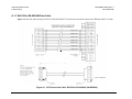
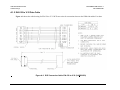
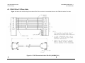
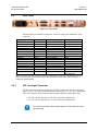
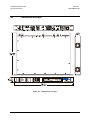
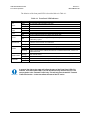
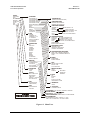
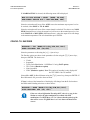
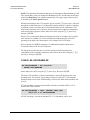
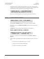
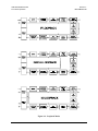
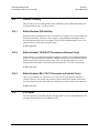
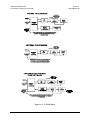
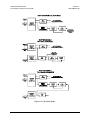
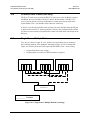
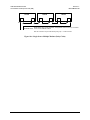
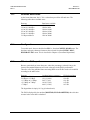
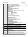
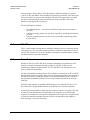
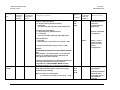
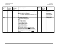
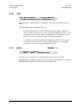
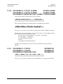
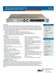
CDM-600 Satellite Modem
Clock Modes and Drop and Insert (D&I)
10.8
Revision 7
MN/CDM600.IOM
Rx Buffer Clock = Insert (D&I only)
The E1 or T1 clock recovery from the IDI G.703 port serves as the Rx Buffer reference.
In addition, the recovered data is the E1/T1 input to the Insert Mux. If the Rx G.703
recovery circuit detects no activity at IDI input, or cannot detect the expected frame
format, Buffer Clock = Rx Satellite will be chosen as a fall-back.
If ‘Insert’ is not the selected buffer clock reference, the clock and data from the IDI port
is ignored, and a new E1/T1 frame is generated. The time slots coming from the satellite
are then re-inserted into the selected timeslots of this new blank frame, and output on the
IDO port.
Single-Source Multiple Modems
Two ways to connect a single T1 or E1 stream to several modems are by looming or
daisy-chaining modems. Each method is illustrated in Figure 10-5 for Looming and
Figure 10-6 for daisy chain and each requires the RX Buffer Clock = Insert setting.
•
•
BIT ERROR TEST
- - - - - - - - - - Receive
___________ Transmit
Figure 10-5. Single-Source Multiple Modems (Looming)
10–10
IDO(RX)
IDI(LOOP)
DDO(LOOP)
DDI(TX)
IDO(RX)
IDI(LOOP)
DDO(LOOP)
DDI(TX)
IDO(RX)
IDI(LOOP)
Assign all timeslots to not overlap.
Assign modems to number of TX/RX channels as required.
DDO(LOOP)
DDI(TX)
10.9
CDM-600 Satellite Modem
Clock Modes and Drop and Insert (D&I)
Revision 7
MN/CDM600.IOM
MODEM
MODEM
MODEM
IDI
DDI
DDO
IDI
Terrestrial Trunk
IDO
Multiple Modem Drop & Insert Application: This application shows how the loop is extended
to one or more additional modems.
DDO- IDI connection may be made internally using Loop = Y under D&I menu.
Figure 10-6. Single-Source Multiple Modems (Daisy Chain)
10–11
CDM-600 Satellite Modem
Clock Modes and Drop and Insert (D&I)
Revision 7
MN/CDM600.IOM
This page is intentionally left blank.
10–12
Chapter 11. EDMAC CHANNEL
11.1
Theory Of Operation
As explained earlier, EDMAC is an acronym for Embedded Distant-end Monitor And
Control. This is a feature that permits the user to access the M&C features of modems
which are at the distant-end of a satellite link.
This is accomplished by adding extra information to the user’s data, but in a manner
which is completely transparent to the user.
On the transmit side:
The data is split into frames - each frame containing 1008 bits (except Rate 21/44 BPSK
Turbo, or when the data rates exceed 2048 kbps, where the frame length is 2928 bits, and
Rate 5/16 BPSK Turbo where the frame length is 3072 bits). 48 bits in each frame are
overhead, and the rest of these bits are the user’s data. This increases the rate of
transmission by 5% (approximately 1.5% for the Turbo BPSK cases, and for all data rates
greater than 2.048 Mbps). For example, if the user’s data rate is 64 kbps, the actual
transmission rate will now be at 67.2 kbps.
At the start of each frame, a 12-bit synchronization word is added. This allows the
demodulator to find and lock to the start of frame. At regular intervals throughout the
frame, additional data bytes and flag bits are added (a further 36 bits in total). It is these
additional bytes that convey the M&C data.
When framing is used, the normal V.35 scrambler is no longer used. This V.35 approach
is called ‘self synchronizing’, because in the receiver, no external information is required
in order for the de-scrambling process to recover the original data. The disadvantage of
this method is that it multiplies errors. On average, if one bit error is present at the input
of the descrambler, 3 output errors are generated. However, there is an alternative when
the data is in a framed format. In this case, a different class of scrambler may be used one which uses the start of frame information to start the scrambling process at an exact
11–1
CDM-600 Satellite Modem
EDMAC Channel
Revision 7
MN/CDM600.IOM
known state. In the receiver, having synchronized to the frame, the de-scrambler can
begin its processing at exactly the right time. This method does not multiply errors, and
therefore has a clear advantage over V.35 scrambling. This is fortunate, as there is a
penalty to be paid for adding the framing. By adding the extra 5% to the transmitted data
rate, the effective Eb/No seen by the user will degrade by a factor of 10log(1.05), or 0.21
dB (0.07dB in the case of the two BPSK Turbo rates). The use of an externally
synchronized scrambler and descrambler almost exactly compensates for this
degradation. The net effect is that the user will see effectively identical BER performance
whether framing is used or not.
On the receive side:
When the demodulator locks to the incoming carrier, it must go through the additional
step of searching for, and locking to the synchronization word. This uniquely identifies
the start of frame, and permits the extraction of the overhead bytes and flag bits at the
correct position within the frame. In addition, the start of frame permits the de-scrambler
to correctly recover the data. The user’s data is extracted, and sent through additional
processing, in the normal manner. The extracted overhead bytes are examined to
determine if they contain valid M&C bytes.
11.2
M&C Connection
Data to be transmitted to the distant-end is sent to a local unit via the remote control port.
A message for the distant-end is indistinguishable from a ‘local’ message - it has the
same structure and content, only the address will identify it as being for a distant-end
unit.
Before the M&C data can be successfully transmitted and received, pairs of units must be
split into EDMAC Masters and EDMAC Slaves. Masters are local to the M&C
Computer, and Slaves are distant-end.
Now, a unit that has been designated an EDMAC master not only responds to its own
unique bus address, but it will also be configured to listen for the address that
corresponds to its EDMAC Slave. When a complete message packet has been received by
the EDMAC Master, it will begin to transmit this packet over the satellite channel, using
the overhead bytes that become available.
Note: The ‘normal’ protocol for the message packet is not used over the satellite path, as
it is subject to errors. For this reason, a much more robust protocol is used which
incorporates extensive error checking.
At the distant-end, the EDMAC slave, configured for the correct address, receives these
bytes, and when a complete packet has been received, it will take the action requested,
and then send the appropriate response to the EDMAC Master, using the return overhead
path on the satellite link. The EDMAC Master assembles the complete packet, and
transmits the response back to the M&C Computer.
11–2
CDM-600 Satellite Modem
EDMAC Channel
Revision 7
MN/CDM600.IOM
Apart from the round-trip satellite delay, the M&C Computer does not see any difference
between local and distant-end units - it sends out a packet, addressed to a particular unit,
and gets back a response. It can be seen that the EDMAC Master simply acts as
forwarding service, in a manner which is completely transparent.
This approach does not require any additional cabling - connection is made using the
normal M&C remote port. Furthermore, the user does not have to worry about
configuring the baud rate of the M&C connection to match the lowest data rate modem in
the system. The M&C system can have mixed data-rate modems, from 2.4 kbps to 2048
kbps, and still run at speeds in excess of 19,200 baud. It should be pointed out that at 2.4
kbps, the effective throughput of the overhead channel is only 11 async
characters/second. For a message of 24 bytes, the time between sending a poll request
and receiving a response will be around 5 seconds. (Note that when either of the BPSK
Turbo rates is in use, the overhead rate is reduced by a factor of three, and therefore the
response time will be around 15 seconds.)
11.3
Setup Summary
To access a distant-end unit:
Designate a Master/Slave pair - Master at the local-end, Slave at the distant-end.
On the local-end unit, enable framing, and EDMAC, define the unit as MASTER,
then enter the bus address. This is constrained to be ‘base 10' meaning that only
addresses such as 10, 20, 30, 40 etc, are allowed.
Choose a unique bus address for the distant-end. This should normally be set to
the ‘base 10' address + 1. For example, if the MASTER unit is set to 30, choose
31 for the distant-end unit.
On the distant-end unit, enable framing, and EDMAC, define the unit as SLAVE,
then enter the bus address. The orange EDMAC Mode LED should be
illuminated.
Set the local-end unit to RS485 remote control, and set the bus address of this
local unit. The orange Remote Mode LED should be illuminated.
Once the satellite link has been established, connect the M&C Computer, and
begin communications, with both the local and distant end units.
NOTE: EDMAC modes are fully compatible with AUPC modes.
11–3
CDM-600 Satellite Modem
EDMAC Channel
11.4
Revision 7
MN/CDM600.IOM
Drop & Insert ++
A new variation of EDMAC is available with D&I++ framing. With this, each frame
contains 2944 bits, with 64 overhead bits and 2880 user data bits. The portion of the
overhead used for the EDMAC link performs identically to that of the EDMAC frame,
but because D&I++ uses a smaller overhead, the two modes are not compatible with each
other.
11–4
Chapter 12. AUTOMATIC UPLINK
POWER CONTROL
12.1
Introduction
Automatic Uplink Power Control (AUPC) is a feature whereby a local modem is
permitted to adjust its own output power level in order to attempt to maintain the Eb/No
at the remote modem.
The user MUST obtain permission from the Satellite
Operator to use this feature.
WARNING
Improper use of this feature could result in a transmitting
terminal seriously exceeding its allocated flux density on the
Operator’s satellite. This could produce interference to
other carriers, and could cause transponder saturation
problems
To accomplish this, either the EDMAC or D&I++ framing types may be used. The
remote modem constantly sends back information about the demodulator Eb/No using
reserved bytes in the overhead structure. The local modem then compares this value of
Eb/No with a pre-defined target value. If the Remote Eb/No is below the target, the local
modem will increase its output power, creating a closed-loop feedback system over the
satellite link. A particularly attractive benefit of this feature is that whenever framed
operation is selected, the remote demodulator’s Eb/No can be viewed from the front
panel display of the local modem. Note that both EDMAC and AUPC can be used
simultaneously with either framing type.
There are several important parameters associated with this mode of operation, and the
user needs to understand how the AUPC feature works, and the implications of setting
these parameters.
12–1
CDM-600 Satellite Modem
Automatic Uplink Power Control (AUPC)
12.2
Revision 7
MN/CDM600.IOM
Setting AUPC Parameters
1) The user, under the menu (CONFIG, MODE) first ensures that EDMAC is
selected. EDMAC may be selected as IDLE, or the unit may be defined as an
EDMAC Master or Slave. The important consideration is that EDMAC framing
should be enabled.
2) The user should verify that the remote modem also has EDMAC framing
enabled.
3) The user, under the menu (CONFIG, TX, POWER) sets the nominal output
power of the modem. This is done by selecting the MANUAL mode, then editing
the TX output power level displayed.
4) The user will then select AUPC as the operating mode. At this point the user will
be prompted to define four key parameters:
12.2.1
Target Eb/No
This is value of Eb/No that the user desires to keep constant at the remote modem.
If the Eb/No exceeds this value, the AUPC control will reduce the TX output power, but
will never drop below the nominal value set.
If the Eb/No falls below this value, the AUPC control will increase the TX output power,
but will never exceed the value determined by the parameter MAX RANGE.
•
•
•
•
12.2.2
The minimum value the user can enter is 0.0 dB
The maximum value the user can enter is 9.9 dB
The default value is 3.0 dB
The resolution is 0.1 dB
Max Range
This defines how much the modem is permitted to increase the output level, under AUPC
control.
• The minimum value the user can enter is 0 dB
• The maximum value the user can enter is 9 dB
• The default value is 1 dB
• The resolution is 1 dB
12–2
CDM-600 Satellite Modem
Automatic Uplink Power Control (AUPC)
12.2.3
Revision 7
MN/CDM600.IOM
Alarm
This parameter defines how the user wants the modem to act if, under AUPC control, the
maximum power limit is reached.
The two choices are:
• NONE (no action)
• TX ALARM (generate a TX alarm)
The default setting is NONE.
12.2.4
Demod Unlock
This defines the action the modem will take if the remote demodulator loses lock.
The two choices are:
• NOMINAL (reduce the TX Output Power to the nominal value)
• MAXIMUM (increase the TX Output Power to the maximum value permitted by the
parameter MAX RANGE)
The default setting is NOMINAL.
(Note that if the local demod loses lock, the modem will automatically move its output
power to the nominal value.)
12.3
Compensation Rate
As with any closed-loop control system, the loop parameters must be chosen to ensure
stability at all times. Several features have been incorporated to ensure that the AUPC
system does overshoot, or oscillate.
•
First, the rate at which corrections to the output power can be made is fixed at once
every 4 seconds. This takes into account the round trip delay over the satellite link,
the time taken for a power change to be reflected in the remote demodulator’s value
of Eb/No, and other processing delays in the modems.
•
Second, if the comparison of actual and target Eb/No yields a result that requires a
change in output power, the first correction made will be 80% of the calculated step.
This avoids the possibility of overshoot. Subsequent corrections are made until the
difference is less than 0.5 dB. At this point, the output power is only changed in
increments of 0.1 dB, to avoid ‘hunting’ around the correct set point.
12–3
CDM-600 Satellite Modem
Automatic Uplink Power Control (AUPC)
12.4
Revision 7
MN/CDM600.IOM
Monitoring
The remote demodulator’s value of Eb/No can be monitored at all times, either from the
front panel (MONITOR, AUPC) or via the remote control interface. The resolution of
the reading is 0.2 dB. For all values greater than or equal to 16 dB, the value 16.0 dB will
be displayed. As long as framing is enabled, the value will still be available, even though
AUPC may be disabled.
Also displayed is the current value of TX power increase. If EDMAC framing is enabled,
but AUPC is disabled, this will indicate 0.0 dB. This value is also available via the
remote control interface.
CAUTION
Comtech EF Data strongly cautions against the use of large values of
permitted power level increase under AUPC control. Users should
consider using the absolute minimum range necessary to improve rainfade margin.
12–4
Chapter 13. ESC++
13.1
Introduction
The ESC++ mode of operation is a new, closed network frame structure which combines
Automatic Uplink Power Control (AUPC) with a high speed asynchronous order-wire
channel. The AUPC works identically to that offered with EDMAC and D&I++ framing,
but is not compatible with either. This is because ESC++ framing uses a different
overhead percentage than the other closed network framing modes.
In order to use this feature, Firmware Version 2.0.1 (or higher) must be installed.
13.2
Overhead Details
Baud rates from 1200 to 38400 bits/sec are offered using RS-232 format. As with the
main remote port (P4B), three data formats are available: 8N1, 7E2 and 7O2. Pins 5 and
6 of P3A are the input and output, respectively, for this data channel. Because 38.4 kbaud
is the maximum rate available, the actual overhead percentage for ESC++ framing
changes as the data rate increases, thereby saving bandwidth at high data rates. The added
overhead is as follows:
Data rate
64 kbps to < 768 kbps
768 kbps to 1.5 Mbps
> 1.5 Mbps to 2.5 Mbps
> 2.5 Mbps to 7 Mbps
> 7 Mbps
Overhead ratio (percentage)
19/17 (11.76%)
12/11 (9.09%)
29/27 (7.4%)
19/18 (5.56%)
64/63 (1.58%)
Note that 64 kbps is the minimum data rate allowable with ESC++. Depending upon code
rate and modulation used, the modem’s maximum data rate of 20 Mbps may be used with
ESC++. In all cases, if the Reed-Solomon outer codec is used, the 126/112 ratio is
employed with ESC++. The new frame structure may be used with any FEC codec type
available with the CDM-600.
13–1
CDM-600 Satellite Modem
ESC++
13.3
Revision 7
MN/CDM600.IOM
Available Baud Rates
At the lowest data rates, the 11.76% overhead may not allow all baud rates. The
following table shows available rates:
Data rate
64 to 127.999 kbps
128 to 191.999 kbps
192 to 255.999 kbps
256 to 383.999 kbps
384 to 511.999 kbps
512 kbps and above
13.4
Baud rates available
1200, 2400, 4800
1200 to 9600
1200 to 14400
1200 to 19200
1200 to 28800
1200 to 38400
Configuration
To use this mode, the user should select ESC++ from the CONFIG, MODE menu. The
baud rate and async character format are then selected from the CONFIG, MISC,
HIGH-RATE ESC menu. This is described in Chapter 6 (Front Panel Operations).
13.5
Effect on Eb/No performance
Because, particularly at lower data rates, where the percentage overhead is large, the
increase in transmitted data rate will cause a decrease in the Eb/No performance.
Therefore, all of the published data concerning BER versus Eb/No needs to be modified
according to the table below:
Data rate
64 kbps to < 768 kbps
768 kbps to 1.5 Mbps
> 1.5 Mbps to 2.5 Mbps
> 2.5 Mbps to 7 Mbps
> 7 Mbps
Overhead ratio (percentage)
19/17 (11.76%)
12/11 (9.09%)
29/27 (7.4%)
19/18 (5.56%)
64/63 (1.58%)
Eb/No degradation
0.48 dB
0.38 dB
0.31 dB
0.23 dB
0.07 dB
The degradation is simply 10 * log (Overhead ratio)
The Eb/No displayed by the modem (MONITOR, RX-PARAMETERS) takes this into
account in the value that is calculated.
13–2
Chapter 14. FLASH UPGRADING
The CDM-600 eliminates the need for updating firmware by physically replacing
EPROMs. Instead, the CDM-600 modem uses ‘flash memory’ technology internally, and
new firmware can be uploaded to the unit from an external PC, as follows:
Go to: www.comtechefdata.com
Click on: downloads
Click on: flash upgrades
This makes software upgrading very simple, and updates can now be sent via the Internet,
E-mail, or on disk. The upgrade can be performed without opening the unit, by simply
connecting the modem to the serial port of a computer.
The cable to connect the PC to the modem is the same as is used for normal EIA-232
remote control, and comprises 3-wires between 9 pin ‘D’ type female connectors. This is
shown in Appendix A.
Comtech EF Data will distribute a free software utility, that is designed to run under
Windows 95/98 or Windows NT. This utility program is called 600Flash.exe, and
should be copied to the user’s computer hard disk. Along with this, the user will receive
the latest firmware file (for example, F1422AD.ccc), which the user should copy to the
same sub-directory (folder).
Before initiating uploading, the 25-pin data connector should be disconnected from the
modem. The user then connects the modem remote control port to an unused serial port
on the user’s computer, and executes the program. The user should follow the
instructions presented on the screen, and the upload will take place automatically.
Following the successful upload process, the modem will automatically re-start, running
the new version of firmware. During this process, the non-volatile RAM, storing the
configuration of the modem, will be erased, so the user is then required to re-enter the
desired configuration parameters.
14–1
CDM-600 Satellite Modem
Flash Upgrading
Revision 7
MN/CDM600.IOM
Full on-line help is provided with 600Flash.exe, but if users experience a problem, or
have a question, they should contact Comtech EF Data Customer Support department.
WARNING
The Remote Control port EIA-232 lines used for Flash upgrading also
are connected to the Primary 25-pin data connector (P3B), and are used
when 1:N Redundancy Switch is connected. Please ensure that
NOTHING is connected to P3B pins 4, 21 and 22 – if these pins are used,
the EIA-232 remote control port will not function, and Flash upgrading
will be impossible.
14–2
Chapter 15. SUMMARY OF
SPECIFICATIONS
15.1
Modulator
Modulation
Symbol rate range
Data rate range
Operating modes
Transmit filtering
BPSK, QPSK, OQPSK, 8-PSK, 8-QAM and 16-QAM
4.8 ksps to 10.0 Msps
See Section 14.9
Open Network, per Intelsat IESS-308/309/310/314 (IDR, IBS/SMS)
E1/T1 Drop and Insert
Transparent, Closed Network, IESS-315 (VSAT Turbo)
Proprietary EDMAC framed mode:
* 5% overhead - all modes except BPSK Turbo, Rate 1/2 OQPSK Turbo, and data rates < 2.048 Mbps
* 1.5% overhead - Rate 21/44, 5/16 Turbo, Rate 1/2 OQPSK Turbo, and all other rates >2.048 Mbps
R-S Outer Codec
st
Turbo Product Codec – Low Rate, 1 Generation (optional):
* Rate 5/16 BPSK
* Rate 21/44 BPSK
* Rate 3/4 QPSK/OQPSK/8-PSK/16-QAM
nd
Turbo Product Codec – High Rate, 2 Generation (optional):
* Rate 21/44 BPSK
* Rate 5/16 BPSK
* Rate 1/2 QPSK/OQPSK (exact Code Rate is actually 0.477)
* Rate 3/4 QPSK/OQPSK/8-PSK/16-QAM
* Rate 7/8 QPSK/OQPSK/8-PSK/16-QAM
* Rate 0.95 QPSK/OQPSK/8-PSK (exact Code Rate is actually 0.944)
nd
LDPC Codec (optional – includes all 2 Generation TPC modes):
* Rate 1/2 BPSK/QPSK/OQPSK
* Rate 2/3 QPSK/OQPSK/8-PSK/8-QAM
* Rate 3/4 QPSK/OQPSK/8-PSK/8-QAM/16-QAM
Automatic Uplink Power Contol (AUPC) mode
High Rate ESC (FAST, with Firmware version. 1.3.1 or higher)
ESC++ (with firmware version 2.0.1 or higher)
Drop & Insert ++ (with firmware version 1.5.0 or higher)
Per INTELSAT IESS-308 (FIR digital filter implementation)
15–1
CDM-600 Satellite Modem
Summary of Specifications
Scrambling
FEC
Output frequency
Harmonics/spurious
Transmit on/off ratio
Output phase noise
Output power
Power accuracy
Output impedance
Output connector
Clocking options
External TX
Carrier Off
Revision 7
MN/CDM600.IOM
IDR Mode, no RS, - per ITU V.35 (Intelsat variant)
IBS mode, no RS - per IESS-309, externally frame synchronized
Transparent Closed Network mode, no R-S or Turbo coding - per ITU V.35 (Intelsat variant)
EDMAC mode, no R-S coding - externally frame synchronized - proprietary
Turbo Product Code mode - externally frame synchronized - proprietary
All R-S modes - externally frame synchronized per IESS-308/309/310
None: Uncoded BPSK/QPSK/OQPSK
Viterbi: k=7, per IESS-308/309
BPSK: Rate 1/2
QPSK/OQPSK: Rate 1/2, Rate 3/4 and Rate 7/8
16-QAM: Rate 3/4 and Rate 7/8 (Viterbi plus Reed-Solomon only)
Sequential:
k=36 (Rate 1/2) per IESS-309
k= 63 (Rate 3/4) per IESS-309
k= 87 (Rate 7/8)
Important note: Sequential decoding limits the data rate to a maximum of 2.048 Mbps for OQPSK and
1.024 Mbps for BPSK.
Reed-Solomon (Open Network):
IDR modes:
225/205 for T1
219/201 for E1 and IESS-310 mode,
194/178 for T2 and E2
IBS modes:
126/112
219/201 for IESS-310 mode
Reed-Solomon (Closed Network):
220,200 outer code (transparent mode)
225,205 outer code (transparent mode, EF Data compatible, V.35 scrambling)
126,112 outer code (transparent mode, IBS parameters, D&I++ mode)
219,201 outer code (transparent mode, IESS-310 parameters)
200,180 outer code (EDMAC modes)
Interleaver depth = 4 or 8 (Viterbi, depending on mode)
Interleaver depth = 8 (Sequential)
8-PSK/TCM Rate 2/3 (Trellis): Per IESS-310
st
Turbo Product Codec, Low Rate (1 Generation) (Optional plug-in card):
Rate 3/4 QPSK/OQPSK/8-PSK/16-QAM - 2 dimensional
Rate 21/44 BPSK - 3 dimensional
Rate 5/16 BPSK - 3 dimensional
nd
Turbo Product Codec, High Rate (2 Generation) (Optional plug-in card):
Rate 5/16 BPSK - 2 dimensional
Rate 21/44 BPSK - 3 dimensional
Rate 1/2 QPSK/OQPSK - 3 dimensional (exact Code Rate is actually 0.477)
Rate 3/4 QPSK/OQPSK/8-PSK/16-QAM - 2 dimensional
Rate 7/8 QPSK/OQPSK/8-PSK/16-QAM - 2 dimensional
Rate 0.95 QPSK/OQPSK/8-PSK - 2 dimensional TPC (exact Code Rate is actually 0.944)
Low Density Parity Check (LDPC) Codec (Optional plug-in card):
Rate 1/2 BPSK/QPSK/OQPSK
Rate 2/3 QPSK/OQPSK/8-PSK/8-QAM
Rate 3/4 QPSK/OQPSK/8-PSK/8-QAM/16-QAM
CDM-600: 52 - 88 MHz, 104 - 176 MHz, 100 Hz resolution – units manufactured prior to February 2005
CDM-600(E): 50 - 90 MHz, 100 - 180 MHz, 100 Hz resolution – units manufactured after February 2005
o
o
Stability ±1.5 ppm, 0 to 50 C (32 to 122 F) (standard stability internal reference)
o
o
Stability ±0.02 ppm, 0 to 50 C (32 to 122 F) (Optional High-stability internal reference)
Better than -55 dBC/4 kHz (typically <-60 dBC/4kHz) – measured from 25 to 400 MHz
55 dB minimum
0
< 0.48 rms double sided, 100 Hz to 1MHz
(minimum of 16 dB better overall than the INTELSAT IESS-308/309 requirement)
0 to -20 dBm, 0.1 dB steps - manual mode. See Automatic Uplink Power Control section also.
±0.5 dB over frequency and temperature
50 and 75 Ω, front panel selectable
21 dB minimum return loss
BNC female
Internal, ±1.5ppm or 0.02 ppm (SCT)
External, locking over a ±100 ppm range (TT)
Loop timing (Rx satellite clock) - supports asymmetric operation - Rx and Tx data rates do not need to be
identical
External Clock
By TTL 'low' signal or external contact closure - hardware function automatically over-rides processor
15–2
CDM-600 Satellite Modem
Remote Control
0.00
0.10
0.20
Revision 7
MN/CDM600.IOM
0.30
0.40
0.50
0.60
0.70
0.80
0.90
1.00
1.10
1.20
0
-5
-10
-15
1.30
1.40
Symbol Rate, Rs
Comtech EF Data
CDM-600 Transmit
Power Spectral Density,
referred to symbol rate
-20
-25
-30
-35
Intelsat
IESS 308/309
Limit
-40
CDM-600 Modulator
typically < -50 dB, and
guaranteed to be
< -45 dB at offsets
> 0.75 Rs
-45
-50
Intelsat
IESS 308/309
Limit
Spectral
density,
dB
-55
15.2
Demodulator
Data rate range, operating modes, de-scrambling, input impedance/return loss etc, as per
Modulator
Input power range
FEC
Acquisition range
Acquisition time
Clock tracking range
-30 to -60 dBm (desired carrier)
+35 dBC maximum composite, up to -5 dBm
Viterbi: 3 bit soft decision
Sequential: 2 bit soft decision
Trellis: Per IESS-310
Reed-Solomon(Open Network): Per IESS-308/309/310
Reed-Solomon(Closed Network): Proprietary
Turbo Product Codec: 6 bit soft decision, proprietary
LDPC: 5 bit soft decision, proprietary
±1 to ±32 kHz, programmable in 1kHz increments
Highly dependent on data rate, FEC rate, and demodulator acquisition range. Examples: 200 ms
average at 64 kbps, R1/2 QPSK, ±32 kHz acquisition sweep range, 6dB Eb/No
5 s average at 9.6 kbps, R1/2 QPSK, ±10 kHz, 6dB Eb/No
Note that Reed-Solomon increases acquisition time, due to the additional time taken for the RS
decoder to declare synchronization.
± 100 ppm min
15–3
1.50
CDM-600 Satellite Modem
Summary of Specifications
VITERBI
BER performance
(met in the presence of
two adjacent carriers,
each 7 dB higher than
the desired carrier)
SEQUENTIAL
@ 64 kbps BER
(met in the presence of
two adjacent carriers,
each 7 dB higher than
the desired carrier)
SEQUENTIAL
@ 1024 kbps BER
(met in the presence of
two adjacent carriers,
each 7 dB higher than
the desired carrier)
VITERBI and RS
220,200 or 200,180
Outer Code BER
(with two adjacent
carriers, each 7 dB
higher than the desired
carrier)
SEQUENTIAL and
RS 220,200 or 200,180
Outer Code @ 512 kbps
(two adjacent carriers,
each 7 dB higher than
the desired carrier)
8-PSK/TCM CODEC
BER
(With two adjacent
carriers, each 7 dB
higher than the desired
carrier)
Revision 7
MN/CDM600.IOM
For:
-5
BER=10
Rate 1/2 (B, Q, OQ)
Guaranteed Eb/No:
(typical value in
parentheses)
Rate 3/4 (Q, OQ)
Guaranteed Eb/No:
(typical value in
parentheses)
Rate 7/8 (Q, OQ)
Guaranteed Eb/No:
(typical value in
parentheses)
5.4 dB (4.9 dB)
6.8 dB (6.3 dB)
7.7 dB (7.2 dB)
BER=10
-6
6.0 dB (5.5 dB)
7.4 dB (6.9 dB)
8.4 dB (7.9 dB)
BER=10
-7
6.7 dB (6.2 dB)
8.2 dB (7.7 dB)
9.0 dB (8.6 dB)
Rate 1/2 (B, Q, OQ)
GuaranteedEb/No:
(typical value in
parentheses)
Rate 3/4 (Q, OQ)
Guaranteed Eb/No:
(typical value in
parentheses)
Rate 7/8 (Q, OQ)
Guaranteed Eb/No:
(typical value in
parentheses)
For:
-5
BER=10
4.8 dB (4.2 dB)
5.8 dB (5.3 dB)
7.0 dB (6.6 dB)
BER=10
-6
5.2 dB (4.5 dB)
6.4 dB (5.8 dB)
7.5 dB (7.2 dB)
BER=10
-7
5.6 dB (4.8 dB)
Rate 1/2 (B, Q, OQ)
Guaranteed Eb/No:
(typical value in
parentheses)
6.9 dB (6.3 dB)
Rate 3/4 (Q, OQ)
Guaranteed Eb/No:
(typical value in
parentheses)
8.0 dB (7.7 dB)
Rate 7/8 (Q, OQ)
Guaranteed Eb/No:
(typical value in
parentheses)
For:
-5
BER=10
5.2 dB (4.8 dB)
5.9dB (5.5dB)
7.2 dB (6.6 dB)
BER=10
-6
5.7 dB (5.2 dB)
6.5dB (6.0dB)
7.7 dB (7.2 dB)
BER=10
-7
6.1 dB (5.7 dB)
Rate 1/2 (B, Q, OQ)
Guaranteed Eb/No:
(typical value in
parentheses)
7.0dB (6.5dB)
Rate 3/4 (Q, OQ)
Guaranteed Eb/No:
(typical value in
parentheses)
8.3 dB (7.7 dB)
Rate 7/8 (Q, OQ)
Guaranteed Eb/No:
(typical value in
parentheses)
4.3 dB (4.0 dB)
5.6 dB (4.7 dB)
6.5 dB (6.0 dB)
For:
-5
BER=10
BER=10
-6
4.4 dB (4.1 dB)
5.8 dB (4.8 dB)
6.7 dB (6.2 dB)
BER=10
-7
4.5 dB (4.2 dB)
Rate 1/2 (B, Q, OQ)
Guaranteed Eb/No:
(typical value in
parentheses)
6.0 dB (5.2 dB)
Rate 3/4 (Q, OQ)
Guaranteed Eb/No:
(typical value in
parentheses)
6.9 dB (6.5 dB)
Rate 7/8 (Q, OQ)
Guaranteed Eb/No:
(typical value in
parentheses)
BER=10
-7
4.6 dB (4.3 dB)
5.3 dB (4.9 dB)
6.0 dB (5.7 dB)
BER=10
-8
4.8 dB (4.5 dB)
Rate 2/3 8-PSK/TCM
Guaranteed Eb/No:
(typical value in
parentheses)
5.6 dB (5.3 dB)
Rate 2/3 8-PSK/TCM
w/concatenated RS
Guaranteed Eb/No:
(typical value in
parentheses)
6.4 dB (6.1 dB)
BER=10
-5
7.9 dB (7.2 dB)
6.3 dB (5.4 dB)
BER=10
-7
9.5 dB (8.7 dB)
6.7 dB (5.8 dB)
BER=10
-8
10.4 dB (9.5dB)
6.9 dB (6.0 dB)
For:
For:
15–4
CDM-600 Satellite Modem
Remote Control
TURBO PRODUCT
CODEC BER
Rate 1/2 QPSK
Rate 21/44 BPSK
Rate 5/16 BPSK
BER
(With two adjacent
carriers, each 7 dB
higher than the desired
carrier)
TURBO PRODUCT
CODEC BER
Rate 3/4 QPSK
Rate 3/4 8-PSK
Rate 3/4 16-QAM
BER
(With two adjacent
carriers, each 7 dB
higher than the desired
carrier)
TURBO PRODUCT
CODEC BER
Rate 7/8 QPSK
Rate 7/8 8-PSK
Rate 7/8 16-QAM
BER
(With two adjacent
carriers, each 7 dB
higher than the desired
carrier)
TURBO PRODUCT
CODEC BER
Rate 0.95 QPSK
Rate 0.95 8-PSK
BER
(With two adjacent
carriers, each 7 dB
higher than the desired
carrier)
16-QAM VITERBI/RS
BER
(With two adjacent
carriers, each 7 dB
higher than the desired
carrier)
LDPC CODEC BER
Rate 1/2 B/Q/OQPSK
Rate 2/3 Q/OQPSK
Rate 1/2 Q/OQPSK
(With two adjacent
carriers, each 7 dB
higher than the desired
carrier)
Revision 7
MN/CDM600.IOM
For:
Rate 1/2 (Q, OQ)
Guaranteed Eb/No:
(typical value in
parentheses)
Rate 21/44 (B)
Guaranteed Eb/No:
(typical value in
parentheses)
Rate 5/16 (B)
Guaranteed Eb/No:
(typical value in
parentheses)
BER=10
-6
2.9 dB (2.6 dB)
2.8 dB (2.5dB)
2.4 dB (2.1dB)
BER=10
-7
3.1 dB (2.7 dB)
3.1 dB (2.8 dB)
2.6 dB (2.3dB)
BER=10
-8
3.3 dB (2.8 dB)
Rate 3/4 (Q, OQ)
Guaranteed Eb/No:
(typical value in
parentheses)
BER=10
-6
3.8dB (3.4dB)
6.2 dB (5.8 dB)
7.4dB (7.0 dB)
BER=10
-7
4.1dB (3.7dB)
6.4 dB (6.0 dB)
7.8 dB (7.3 dB)
BER=10
-8
4.4dB (4.0dB)
6.8 dB (6.3 dB)
8.2 dB (7.7 dB)
Rate 7/8 (Q, OQ)
Guaranteed Eb/No:
(typical value in
parentheses)
Rate 7/8 (8-PSK)
Guaranteed Eb/No:
(typical value in
parentheses)
Rate 7/8 (16-QAM)
Guaranteed Eb/No:
(typical value in
parentheses)
For:
For:
3.3 dB (2.90dB)
Rate 3/4 (8-PSK)
Guaranteed Eb/No:
(typical value in
parentheses)
2.7 dB (2.4dB)
Rate 3/4 (16-QAM)
Guaranteed Eb/No:
(typical value in
parentheses)
BER=10
-6
4.3 dB (4.0 dB)
7.0 dB (6.6 dB)
8.1 dB (7.7 dB)
BER=10
-7
4.4 dB (4.1 dB)
7.1 dB (6.7 dB)
8.2 dB (7.8 dB)
BER=10
-8
4.5 dB (4.2 dB)
7.2 dB (6.8 dB)
8.3 dB (7.9 dB)
For:
Rate 0.95 (Q, OQ)
Guaranteed Eb/No:
(typical value in
parentheses)
Rate 0.95 (8-PSK)
Guaranteed Eb/No:
(typical value in
parentheses)
BER=10
-6
6.4 dB (6.0 dB)
9.3 dB (8.9 dB)
BER=10
-7
6.7 dB (6.3 dB)
9.8 dB (9.4 dB)
BER=10
-8
6.9 dB (6.5 dB)
10.3 dB (9.9 dB)
16-QAM Rate 3/4
Viterbi/RS
Guaranteed Eb/No:
(typical value in
parentheses)
16-QAM Rate 7/8
Viterbi/RS
Guaranteed Eb/No:
(typical value in
parentheses)
For:
BER=10
-6
8.1 dB (7.5 dB)
9.5 dB (9.0 dB)
BER=10
-8
8.6 dB (8.0 dB)
BPSK/QPSK/OQPSK
Rate 1/2 LDPC
Guaranteed Eb/No:
(typical value in
parentheses)
10.1 dB (9.5 dB)
QPSK/OQPSK
Rate 2/3 LDPC
Guaranteed Eb/No:
(typical value in
parentheses)
QPSK/OQPSK
Rate 3/4 LDPC
Guaranteed Eb/No:
(typical value in
parentheses)
For:
BER=10
-5
2.0 dB (1.7 dB)
2.3 dB (2.0 dB)
3.0 dB (2.6 dB)
BER=10
-9
2.3 dB (2.0 dB)
2.7 dB (2.3 dB)
3.3 dB (3.0 dB)
15–5
CDM-600 Satellite Modem
Summary of Specifications
LDPC CODEC BER
Rate 2/3 8-PSK
Rate 3/4 8-PSK
(With two adjacent
carriers, each 7 dB
higher than the desired
carrier)
LDPC CODEC BER
Rate 2/3 8-QAM
Rate 3/4 8-QAM
(With two adjacent
carriers, each 7 dB
higher than the desired
carrier)
LDPC CODEC BER
Rate 3/4 16-QAM
(With two adjacent
carriers, each 7 dB
higher than the desired
carrier)
Revision 7
MN/CDM600.IOM
For:
8-PSK Rate 2/3 LDPC
Guaranteed Eb/No:
(typical value in
parentheses)
8-PSK Rate 3/4 LDPC
Guaranteed Eb/No:
(typical value in
parentheses)
BER=10
-5
-
5.7 dB (5.3 dB)
BER=10
-9
5.7 dB (5.2 dB)
8-QAM Rate 2/3 LDPC
Guaranteed Eb/No:
(typical value in
parentheses)
6.0 dB (5.6 dB)
8-QAM Rate 3/4 LDPC
Guaranteed Eb/No:
(typical value in
parentheses)
BER=10
-5
4.6 dB (4.2 dB)
5.2 dB (4.7 dB)
BER=10
-9
5.0 dB (4.6 dB)
16-QAM Rate 3/4 LDPC
Guaranteed Eb/No:
(typical value in
parentheses)
5.7 dB (5.3 dB)
-5
6.8 dB (6.2 dB)
For:
For:
BER=10
-5
BER=10
7.1 dB (6.8 dB)
Selectable size of 64 to 262,144 bits, in 16-bit steps (with added limitations for G.704 frame
boundaries)
Size selection is displayed in bytes and milliseconds
Supports asymmetric operation - when buffer is clocked from Tx clock, Rx and Tx rates do not need to
be identical
Eb/No estimate, 2 to 16 dB (± 0.25 dB accuracy)
Corrected Bit Error Rate, 1E-3 to 1E-10
Frequency offset, ± 32 kHz range, 100 Hz resolution
Buffer fill state, in percent
Receive signal level (-20 to -60 dBm, accuracy is ± 2.5 dB)
Plesiochronous/
Doppler Buffer
Monitor Functions
15.3
Data Interfaces
Primary Data
(3 selectable modes)
G.703 (Tx In, Drop Out,
Insert In, Rx Out)
External Reference In
Overhead Data
RS-422/EIA-530 DCE (Rates up to 10 Mbps)
(also supports X.21 DCE & DTE and 8k ESC orderwire for IDR)
V.35 DCE (Rates up to 10 Mbps)
Synchronous EIA-232 (Rates up to 300 kbps)
LVDS serial (Rates up to 20 Mbps)
HSSI - Requires optional CIC-20 Converter (Rates up to 20 Mbps)
1.544 Mbps T1 (Balanced 100 Ω)
6.312 Mbps T2 (unbalanced 75 Ω or balanced 110 Ω)
2.048 Mbps E1 (unbalanced 75 Ω or balanced 120 Ω)
8.448 Mbps E2 (unbalanced 75 Ω)
Note: All Drop and Insert modes are a FAST option.
2.4 kHz - 10 MHz, in 1 Hz steps (locks baseband clocks only)
TTL level (unbalanced) or sine wave @ 0dBm nominal
RS-422 octet clocks for IDR ESC & IBS
RS-422 IDR 64 kbps ESC data & clock
RS-232 IBS ESC data & clock
RS-422 External Clock input
IDR BWA Inputs
RS-232 High Rate ESC data (FAST, with Firmware V. 1.3.1 or higher)
RS-232 ESC++ data ( with Firmware V. 2.0.1 or higher)
15–6
25-pin D-sub (female)
15-pin D-sub (female)
or BNC (female)
BNC (female)
25-pin D-sub (male)
CDM-600 Satellite Modem
Remote Control
Modem Alarms
Relay outputs (Tx, Rx & unit faults)
Demodulator I & Q test outputs (constellation)
Demodulator Rx Signal Level output (0 to 2.5 volts)
External carrier off input
4 backward alarm Form C relay outputs
IDR BWA Outputs
Remote Control
ADPCM Audio Interface
Auxiliary Serial
15.4
Revision 7
MN/CDM600.IOM
15-pin D-sub (male)
15-pin D-sub (female)
RS-232 or RS-485 modem control and monitoring
2 audio channels, each occupying 32 kbps bandwidth as part of IDR
overhead or as a 64 kbps primary data rate option.
600 Ω balanced – 0 dBm0 nominal, -6 to +8 dB, 2 dB steps
RS-232 link to other modem in 1:1 pair, via CRS-150
9-pin D-sub (male)
9-pin D-sub (female)
USB Type B Socket
Automatic Uplink Power Control
Operating Mode
Target Eb/No range
Max AUPC range
Monitor functions
15.5
Requires Closed Network Framed mode (EDMAC, D&I++, or ESC++) for transport of Eb/No information
from remote modem (EDMAC can be enabled or disabled)
0 to 9.9 dB at remote demod (default is 4.0 dB)
0 to 9 dB (default is 3 dB)
Remote demod Eb/No
Tx power level increase
(front panel or via remote control interface)
Framing Summary
Transparent
None
EDMAC
To 2 Mbps:
1.5%
Above 2 Mbps:
1.5%
(see Note 2)
IDR
Fixed 96 kHz
IBS
1/15 of front
panel data rate
D&I
1/15 of front
panel data rate
Terrestrial is T1
or E1
D&I++
1/45 of front
panel data
rate
Terrestrial is
T1 or E1
Available
data rates
and format
Overhead
components
All rates and
formats
All rates and
formats
T1, E1, T2 and
E2; all formats
None
Remote control
link between
modems’
processor
plus AUPC
EIA-422 ESC
(8 kbps)
EIA-422 ESC
(64 kbps or 2
audio links)
4 BW alarms
64 to 2048
kbps only; all
formats
EIA-232 Earth
station link at
th
1/480 of
primary data
rate
One BW alarm
Specific
multiples of 64
kbps only
EIA-232 Earth
station link at
th
1/480 of
primary data
rate
One BW alarm
Additional
ReedSolomon
Overhead
Scrambling
(see
Note 1 )
200/180
219/201 for
IESS-310
mode
Basic ITU
V.35
(Intelsat)
200/180
T1 = 225/205
E1 = 219/201 and
IESS-310 mode
T2/E2 = 94/178
Basic ITU V.35
(Intelsat)
126/112
219/201 for
IESS-310 mode
126/112
219/201 for
IESS-310 mode
Any multiple
of 64 kbps, up
to n = 24.
Same as
EDMAC, plus
EIA-232 Earth
station link at
th
1/576 of
primary data
rate
126/112
126/112
IESS-309
scrambler
IESS-309
scrambler
Basic ITU
V.35 (Intelsat)
Proprietary
scrambler
Overhead
added
Proprietary
scrambler
Notes:
1. Reed-Solomon is Off.
2. 1.5 % for Rates 5/16 or 21/44 BPSK Turbo, Rate 1/2 QPSK/OQPSK Turbo, and all rates > 2 Mbps
15–7
ESC++
Variable:
between
11.76% at
64 kbps
to 1.58%
above
7 Mbps
All rates
and formats
EIA-232
Earth
station link
at variable
rate, plus
AUPC
CDM-600 Satellite Modem
Summary of Specifications
15.6
Revision 7
MN/CDM600.IOM
Data Rate Ranges
Code Rate/Modulation
FEC Type
Data Rate Range
Uncoded BPSK
None
4.8 kbps to 10.0 Mbps
Uncoded QPSK/OQPSK
None
9.6 kbps to 20 Mbps
Rate 1/2 BPSK
Viterbi
2.4 kbps to 5.0 Mbps
Rate 1/2 BPSK
Sequential
2.4 kbps to 1.024 Mbps
Rate 1/2 BPSK
Viterbi with R-S
2.4 kbps to 4.444 Mbps
Rate 1/2 BPSK
Sequential with R-S
2.4 kbps to 1.024 Mbps
Rate 1/2 QPSK/OQPSK
Viterbi
4.8 kbps to 10.0 Mbps
Rate 1/2 QPSK/OQPSK
Sequential
4.8 kbps to 2.048 Mbps
Rate 1/2 QPSK/OQPSK
Viterbi with R-S
4.8 kbps to 8.888 Mbps
Rate 1/2 QPSK/OQPSK
Sequential with R-S
4.8 kbps to 2.048 Mbps
Rate 3/4 QPSK/OQPSK
Viterbi
7.2 kbps to 15 Mbps
Rate 3/4 QPSK/OQPSK
Sequential
7.2 kbps to 2.048 Mbps
Rate 3/4 QPSK/OQPSK
Viterbi with R-S
7.2 kbps to 13.333 Mbps
Rate 3/4 QPSK/OQPSK
Sequential with R-S
7.2 kbps to 2.048 Mbps
Rate 7/8 QPSK/OQPSK
Viterbi
8.4 kbps to 17.5 Mbps
Rate 7/8 QPSK/OQPSK
Sequential
8.4 kbps to 2.048 Mbps
Rate 7/8 QPSK/OQPSK
Viterbi with R-S
8.4 kbps to 15.555 Mbps
Rate 7/8 QPSK/OQPSK
Sequential with R-S
8.4 kbps to 2.048 Mbps
Rate 2/3 8-PSK
TCM
9.6 kbps to 20.0 Mbps
Rate 2/3 8-PSK
TCM with R-S
9.6 kbps to 17.777 Mbps
Rate 3/4 16-QAM
Viterbi with R-S
14.4 kbps to 20.0 Mbps
Rate 7/8 16-QAM
Viterbi with R-S
16.8 kbps to 20.0 Mbps
Rate 21/44 BPSK
TPC
4.8 kbps to 3.2 Mbps (to 4.77 Mbps with High Rate Turbo card)
Rate 5/16 BPSK
TPC
4.8 kbps to 2.048 Mbps(to 3.12 Mbps with High Rate Turbo card)
Rate 3/4 QPSK/OQPSK
TPC
7.2 kbps to 5.0 Mbps (to 15 Mbps with High Rate Turbo card)
Rate 3/4 8-PSK
TPC
10.8 kbps to 5.0 Mbps (to 20 Mbps with High Rate Turbo card)
Rate 3/4 16-QAM
TPC
14.4 kbps to 5.0 Mbps (to 20 Mbps with High Rate Turbo card)
Rate 1/2 QPSK/OQPSK
TPC
4.8 kbps to 9.54 Mbps
(High Rate Turbo card only)
Rate 7/8 QPSK/OQPSK
TPC
8.4 kbps to 17.5 Mbps
(High Rate Turbo card only)
Rate 0.95 QPSK/OQPSK
TPC
9.1 kbps to 18.888 Mbps
(High Rate Turbo card only)
Rate 7/8 8-PSK
TPC
12.6 kbps to 20 Mbps
(High Rate Turbo card only)
Rate 0.95 8-PSK
TPC
13.6 kbps to 20 Mbps
(High Rate Turbo card only)
Rate 7/8 16-QAM
TPC
16.8 kbps to 20 Mbps
(High Rate Turbo card only)
Rate 1/2 BPSK
LDPC
2.4 kbps to 5.0 Mbps
Rate 1/2 QPSK/OQPSK
LDPC
4.8 kbps to 10.0 Mbps
Rate 2/3 QPSK/OQPSK
LDPC
6.4 kbps to 13.333 Mbps
Rate 3/4 QPSK/OQPSK
LDPC
7.2 kbps to 15.0 Mbps
Rate 2/3 8-PSK/8-QAM
LDPC
9.6 kbps to 19.0 Mbps
Rate 3/4 8-PSK/8-QAM
LDPC
10.8 kbps to 20.0 Mbps
Rate 3/4 16-QAM
LDPC
14.4 kbps to 20.0 Mbps
Important Notes:
1) If EDMAC framing is employed, the upper data rate will be reduced by 5% for data rates up to 2.048 Mbps, and by 1.58% for
data rates above 2.048 Mbps)
2) If ESC++ framing is employed, the upper data rate will be reduced 1.58%.
15–8
CDM-600 Satellite Modem
Remote Control
15.7
Miscellaneous
Front panel
Loopbacks
Fault relays
M&C Interface
M&C Software
Dimensions
Weight
AC consumption
Operating voltage
Operating temperature
15.8
Revision 7
MN/CDM600.IOM
Tactile keypad, 6 keys (Up/Down, Left/Right, Enter/Clear)
Vacuum Fluorescent Display (blue) - 2 lines of 40 characters
Internal IF loopback, RF loopback, digital loopback, and inward/outward loopback
Hardware fault, Rx and Tx Traffic Alarms, Open Network Backward Alarms
EIA-232 and EIA-485 (addressable multidrop, 2-wire or 4-wire)
SATMAC or CMCS software for control of local and distant units
1U high, 12 inches (305 mm) deep
10 lbs (4.5 kgs) max
25 watts (typical) 40 watts (maximum)
100 - 240 volts AC, +6%/-10% - autosensing
(total absolute max. range is 90 - 254 volts AC)
o
o
0 to 50 C (32 to 122 F)
Approvals
“CE” as follows:
EN 55022 Class B (Emissions)
EN 50082-1 (Immunity)
EN 60950 (Safety)
FCC
FCC Part 15 Class B
EN 61000-3-2
EN 61000-3-3
EN 61000-4-2
EN 61000-4-4
EN 61000-4-5
15–9
EN 61000-4-6
EN 61000-4-8
EN 61000-4-9
EN 61000-4-11
EN 61000-4-13
CDM-600 Satellite Modem
Summary of Specifications
Revision 7
MN/CDM600.IOM
This page is intentionally left blank.
15–10
Chapter 16. REMOTE CONTROL
16.1
Introduction
This section describes the protocol and message command set for remote monitor and
control of the CDM-600 Modem.
The electrical interface is either an EIA-485 multi-drop bus (for the control of many
devices) or an EIA-232 connection (for the control of a single device), and data is
transmitted in asynchronous serial form, using ASCII characters. Control and status
information is transmitted in packets, of variable length, in accordance with the structure
and protocol defined in later sections.
16.2
EIA-485
For applications where multiple devices are to be monitored and controlled, a full-duplex
(or 4-wire) EIA-485 is preferred. Half-duplex (2-wire) EIA-485 is possible, but is not
preferred.
In full-duplex EIA-485 communication there are two separate, isolated, independent,
differential-mode twisted pairs, each handling serial data in different directions. It is
assumed that there is a ‘controller’ device (a PC or dumb terminal), which transmits data,
in a broadcast mode, via one of the pairs. Many ‘target’ devices are connected to this
pair, which all simultaneously receive data from the controller. The controller is the only
device with a line-driver connected to this pair - the target devices only have linereceivers connected.
In the other direction, on the other pair, each target has a tri-stateable line driver
connected, and the controller has a line-receiver connected. All the line drivers are held in
high-impedance mode until one (and only one) target transmits back to the controller.
16–1
CDM-600 Satellite Modem
Remote Control
Revision 7
MN/CDM600.IOM
Each target has a unique address, and each time the controller transmits, in a framed
‘packet’ of data, the address of the intended recipient target is included. All of the targets
receive the packet, but only one (the intended) will reply. The target enables its output
line driver, and transmits its return data packet back to the controller, in the other
direction, on the physically separate pair.
EIA 485 (full duplex) summary:
•
•
•
16.3
Two differential pairs - one pair for controller to target, one pair for target to
controller.
Controller-to-target pair has one line driver (controller), and all targets have linereceivers.
Target-to-controller pair has one line receiver (controller), and all targets have
tri-state drivers.
EIA-232
This is a much simpler configuration in which the controller device is connected directly
to the target via a two-wire-plus-ground connection. Controller-to-target data is carried,
via EIA-232 electrical levels, on one conductor, and target-to-controller data is carried in
the other direction on the other conductor.
16.4
Basic Protocol
Whether in EIA-232 or EIA-485 mode, all data is transmitted as asynchronous serial
characters, suitable for transmission and reception by a UART. In this case, the
asynchronous character formats include 7O2, 7E2, and 8N1. The baud rate may vary
between 1200 and 38,400 baud.
All data is transmitted in framed packets. The controller is assumed to be a PC or ASCII
dumb terminal, which is in charge of the process of monitor and control. The controller is
the only device that is permitted to initiate, at will, the transmission of data. Targets are
only permitted to transmit when they have been specifically instructed to do so by the
controller.
All bytes within a packet are printable ASCII characters, less than ASCII code 127. In
this context, the Carriage Return and Line Feed characters are considered printable.
All messages from controller to target require a response (with one exception). This will
be either to return data that has been requested by the controller, or to acknowledge
reception of an instruction to change the configuration of the target. The exception to this
is when the controller broadcasts a message (such as Set time/date) using Address 0,
when the target is set to EIA-485 mode.
16–2
CDM-600 Satellite Modem
Remote Control
16.5
Revision 7
MN/CDM600.IOM
Packet Structure
Controller-to-target:
Start of Packet
Target Address
<
ASCII code 60
(1 character)
(4 characters)
Address
De-limiter
/
ASCII code 47
Instruction
Code
(1 character)
(3 characters)
Code
Qualifier
= or ?
ASCII code
61 or 63
(1 character)
Optional
Arguments
End of Packet
Carriage
Return
ASCII code 13
(n characters)
(1 character)
Example:
<0135/TFT=1[CR]
Target-to-controller:
Start of Packet
>
ASCII
code 62
(1 character)
Target
Address
(4 characters)
Address
De-limiter
/
ASCII
code 47
(1 character)
Instruction
Code
Example:
>0654/RSW=32[CR][LF]
(3 characters)
Code Qualifier
=, ?, !, or *
ASCII code 61,
63, 33 or 42
(1 character)
Optional
Arguments
(From 0 to n
characters)
End of Packet
Carriage Return,
Line Feed
ASCII code 13,10
(2 characters)
Each of the components of the packet is now explained.
16.5.1
Start Of Packet
Controller to Target: This is the character ‘<’ (ASCII code 60)
Target to Controller: This is the character ‘>’ (ASCII code 62)
Because this is used to provide a reliable indication of the start of packet, these two
characters may not appear anywhere else within the body of the message.
16.5.2
Address
Up to 9,999 devices can be uniquely addressed. In EIA-232 applications this value is set
to 0. In EIA-485 applications, the permissible range of values is 1 to 9999. It is
programmed into a target unit using the front panel keypad.
Important note: The controller sends a packet with the address of a target - the destination
of the packet. When the target responds, the address used is the same address, to indicate
to the controller the source of the packet. The controller does not have its own address.
16–3
CDM-600 Satellite Modem
Remote Control
16.5.3
Revision 7
MN/CDM600.IOM
Instruction Code
This is a three-character alphabetic sequence that identifies the subject of the message.
Wherever possible, the instruction codes have been chosen to have some significance.
For example TFQ for transmit frequency, RMD for receive modulation type, etc. This
aids in the readability of the message, should it be displayed in its raw ASCII form. Only
upper case alphabetic characters may be used (A-Z, ASCII codes 65 - 90).
16.5.4
Instruction Code Qualifier
This is a single character that further qualifies the preceding instruction code.
Code Qualifiers obey the following rules:
1)
From Controller to Target, the only permitted values are:
= (ASCII code 61)
? (ASCII code 63)
They have these meanings:
The ‘=’ code (controller to target) is used as the assignment operator, and is used to
indicate that the parameter defined by the preceding byte should be set to the value of the
argument(s) which follow it.
For example, in a message from controller to target, TFQ=070.0000 would mean ‘set the
transmit frequency to 70 MHz’
The ‘?’ code (controller to target) is used as the query operator, and is used to indicate
that the target should return the current value of the parameter defined by the preceding
byte.
For example, in a message from controller to target, TFQ? would mean ‘return the
current value of the transmit frequency’
2)
From Target to Controller, the only permitted values are:
= (ASCII code 61)
? (ASCII code 63)
! (ASCII code 33)
* (ASCII code 42)
# (ASCII code 35)
~ (ASCII Code 126)
They have these meanings:
The ‘=’ code (target to controller) is used in two ways:
First, if the controller has sent a query code to a target (for example TFQ?, meaning
‘what’s the Transmit frequency?’), the target would respond with TFQ=xxx.xxxx, where
xxx.xxxx represents the frequency in question.
16–4
CDM-600 Satellite Modem
Remote Control
Revision 7
MN/CDM600.IOM
Second, if the controller sends an instruction to set a parameter to a particular value, then,
providing the value sent in the argument is valid, the target will acknowledge the
message by replying with TFQ= (with no message arguments).
The ? code (target to controller) is only used as follows:
If the controller sends an instruction to set a parameter to a particular value, then, if the
value sent in the argument is not valid, the target will acknowledge the message by
replying (for example) with TFQ? (with no message arguments). This indicates that there
was an error in the message sent by the controller.
The * code (target to controller) is only used as follows:
If the controller sends an instruction to set a parameter to a particular value, then, if the
value sent in the argument is valid, BUT the modem will not permit that particular
parameter to be changed at that time, the target will acknowledge the message by
replying (for example) with TFQ* (with no message arguments).
The ! code (target to controller) is only used as follows:
If the controller sends an instruction code which the target does not recognize, the target
will acknowledge the message by echoing the invalid instruction, followed by the !
character with. Example: XYZ!
The # code (target to controller) is only used as follows:
If the controller sends a correctly formatted command, BUT the modem is not in remote
mode, it will not allow reconfiguration, and will respond with TFQ#.
The ~ code (target to controller) is only used as follows:
If a message was sent via a local modem to a distant end device or ODU, the message
was transmitted transparently through the local modem. In the event of the distant-end
device not responding, the local modem would generate a response e.g. 0001/RET~,
indicating that it had finished waiting for a response and was now ready for further
comms.
16.5.5
Message Arguments
Arguments are not required for all messages. Arguments are ASCII codes for the
characters 0 to 9 (ASCII 48 to 57), A to Z (ASCII 65 to 90), period (ASCII 46), space
(ASCII 32), * (ASCII 42), + (ASCII 43), - (ASCII 45), / (ASCII 47), and comma
(ASCII 44).
16.5.6
End Of Packet
Controller to Target: This is the ‘Carriage Return’ character (ASCII code 13)
Target to Controller: This is the two-character sequence ‘Carriage Return’, ‘Line Feed’.
(ASCII code 13, and code 10.)
Both indicate the valid termination of a packet.
16–5
CDM-600 Satellite Modem
Remote Control
16.6
A
ADJ?, 16–25
APP?, 16–13
AUP?, 16–13
B
BFS?, 16–33
C
CAE=, 16–32
CAS=, 16–31
CID?, 16–27
CLD=, 16–29
CST=, 16–29
CTD?, 16–26
D
Revision 7
MN/CDM600.IOM
Alphabetical list of Remote Commands
ITD?, 16–14
ITS?, 16–39
ITY?, 16–22
L
LRS?, 16–34
M
MGC?, 16–28
MGC?n, 16–28
MSK?, 16–26
N
NUE?, 16–31
NUS?, 16–30
O
ODU?, 16–27
DAY?, 16–29
DNI?, 16–38
DNI?n, 16–38
DTS?, 16–38
DTY?, 16–15
E
EBA?, 16–21
EBN?, 16–33
EFM?, 16–23
EFR?, 16–25
EID?, 16–36
ESA?, 16–23
ESC?, 16–24
F
FCS?, 16–35
FLT?, 16–32
FSW=, 16–39
I
IEP=, 16–32
IRD?, 16–21
ISP=, 16–31
P
PLI?, 16–14
R
RBA?, 16–22
RBS?, 16–21
RCB=, 16–29
RCK?, 16–21
RCR?, 16–18
RDR?, 16–19
RDS?, 16–20
REB?, 16–14
RED?, 16–34
REF?, 16–20
RET?, 16–23
RFM?, 16–17
RFO?, 16–33
RFQ?, 16–16
RFT?, 16–17
RIP?, 16–23
RIT?, 16–16
RMD?, 16–18
RNE?, 16–32
16–6
RNS?, 16–30
RRS?, 16–20
RSI?, 16–20
RSL?, 16–33
RSW?, 16–21
RTC, 16–22
RTE?, 16–22
RVL?, 16–22
S
SCP?, 16–24
SNO?, 16–34
SSI?, 16–30
SWR?, 16–34
T
TBA?, 16–15
TCK?, 16–14
TCR?, 16–11
TDR?, 16–11
TET?, 16–15
TFM?, 16–9
TFQ?, 16–4
TFT?, 16–10
TIM?, 16–29
TIP?, 16–16
TIT?, 16–9
TMD?, 16–10
TMP?, 16–35
TPL?, 16–12
TRS?, 16–12
TSC?, 16–12
TSI?, 16–12
TST?, 16–26
TTA?, 16–15
TTC?, 16–15
TVL?, 16–14
TXO?, 16–13
W
WRM?, 16–25
CDM-600 Satellite Modem
Remote Control
Command
(Instruction
Code and
Qualifier)
TFQ=
Arguments for
Command or
Response to
Query
8 bytes
Tx
Interface
Type
TIT=
1 byte, value
of 0 thru 6
Tx
Framing
Mode
TFM=
1 byte, value
of 0 thru 6
Parameter
Type
Tx
Frequency
Revision 7
MN/CDM600.IOM
Response
to
Command
Description of Arguments
Command or Query.
With hardware revision xx.0: standard frequency range:
52 MHz to 88 MHz, or 104 MHz to 176 MHz.
With hardware revision xx.1: extended frequency range:
50 MHz to 90 MHz, or 100 MHz to 180 MHz.
(Use HRV? to obtain the hardware revision level)\
Resolution=100Hz.
Example: TFQ=072.9872
Note: The CDM600 supports both 70 and 140 MHz bands.
Command or Query.
Tx Interface Type, where:
0=RS422
1=V.35
2=RS232 (synchronous)
3=Balanced G.703
4=Unbalanced G.703
5=Audio (Data rate fixed at 64 kbps) (IBS/EDMAC only)
6=LVDS
Example: TIT=1 (selects V.35)
Command or Query.
Tx Framing mode, where:
0=Unframed
1=IBS
2=IDR
3=DROP (requires D&I FAST option)
4=EDMAC
5=D&I++ (requires D&I FAST option) (version 1.5.0 or
higher)
6=ESC++ (requires version 2.0.1 or higher)
Example: TFM=0 (selects Unframed mode)
TFQ=
TFQ?
TFQ*
TFQ#
Query
(Instruction
Code and
Qualifier)
TFQ?
Response to Query
TFQ=xxx.xxxx
(see description of
arguments)
TIT=
TIT?
TIT*
TIT#
TIT?
TIT=x
(see description of
arguments)
TFM=
TFM?
TFM*
TFM#
TFM?
TFM=x
(see description of
arguments)
Priority System = TIT (Highest priority) , TFM, TFT, TMD, TCR, and TDR (Lowest Priority), indicated by shading. Any change to a higher
priority parameter can override any of the parameters of lower priority.
16–7
CDM-600 Satellite Modem
Remote Control
Revision 7
MN/CDM600.IOM
Exception: Select DROP or D&I++ mode using TFM (Transmit Framing type) which is highest priority
Parameter
Type
Tx FEC Type
Tx
Modulation
Type
Command
(Instruction
Code and
Qualifier)
TFT=
Arguments
for Command
or Response
to Query
1 byte, value
of 0 thru 9
TMD=
1 byte, value
of 0 thru 5
Response
to
Command
Description of Arguments
Command or Query.
Tx FEC coding type, where:
0=None (uncoded, rate 1/1) with differential encoding
ON
1=Viterbi
2=Viterbi + Reed-Solomon
3=Sequential
4=Sequential + Reed-Solomon
5=TCM (Trellis Code Modulation) (Forces TCR=3 2/3)
6=TCM + Reed-Solomon (Forces TCR=3 2/3)
7=Turbo (TPC)
8=None (uncoded, rate 1/1) with differential encoding
OFF
9=LDPC (Requires TPC/LDPC Codec)
Example: TFT=1 (which is Viterbi coding)
Command or Query.
Tx Modulation type, where:
0=BPSK
1=QPSK
2=OQPSK
3=8-PSK
4=16-QAM (Turbo or Viterbi + RS only)
5=8-QAM (LDPC only) (Requires TPC/LDPC Codec and
FAST option.)
Depending on FEC type, not all of these selections will
be valid.
Example: TMD=2 (which is OQPSK)
16–8
TFT=
TFT?
TFT*
TFT#
TMD=
TMD?
TMD*
TMD#
Query
(Instruction
Code and
Qualifier)
TFT?
TMD?
Response to Query
TFT=x
(see description of
arguments)
TMD=x
(see description of
arguments)
CDM-600 Satellite Modem
Remote Control
Parameter
Type
Tx FEC Code
Rate
Command
(Instruction
Code and
Qualifier)
TCR=
Arguments
for Command
or Response
to Query
1 byte, value
of 0 thru 7
Revision 7
MN/CDM600.IOM
Response
to
Command
Description of Arguments
Command or Query
Tx Modulation Type, where:
0=Rate 1/2
1=Rate 3/4
2=Rate 7/8
3=Rate 2/3 (8-PSK TCM or LDPC only)
4=Rate 1/1 (Uncoded or No FEC)
5=Rate 21/44 (Turbo Only)
6=Rate 5/16 (Turbo Only)
7=Rate 0.95 (Turbo Only)
TCR=
TCR?
TCR*
TCR#
Query
(Instruction
Code and
Qualifier)
TCR?
Response to Query
TCR=x
(see description of
arguments)
Depending on FEC type, not all of these selections will
be valid.
Tx Data Rate
TDR=
9 bytes
Example: TCR=1 (which is Rate 3/4)
Command or Query.
Tx Data rate, in kbps, between 2.4 kbps and 20 Mbps
Resolution=1 bps
Example: TDR=02047.999 (which is 2047.999 kbps)
For Hardware Version 2.0 or higher, and Firmware 1.3.1
or higher, additional auxiliary G.703 sub-rates are
available. These are selected using:
00512.AUX
01024.AUX
02048.AUX
The connectors used for the Aux rates are IDI/DDO.
These Aux rates are not available with Drop & Insert or
IDR.
16–9
TDR=
TDR?
TDR*
TDR#
TDR?
TDR=xxxxx.xxx
(see description of
arguments)
CDM-600 Satellite Modem
Remote Control
Parameter
Type
Tx
ReedSolomon
Encoding
Command
(Instruction
Code and
Qualifier)
TRS=
Arguments
for Command
or Response
to Query
1 byte, value
of 0 thru 3
Tx Spectrum
Invert
TSI=
1 byte, 0 or 1
Tx Scrambler
TSC=
1 byte, 0 or 1
Tx Power
Level
TPL=
4 bytes
Revision 7
MN/CDM600.IOM
Response
to
Command
Description of Arguments
Command or Query.
Tx RS encoding
0=Normal (based on the Open Network framing mode
selected)
1=IESS-310 mode, available all framing modes, except
EDMAC.
2=EF Data legacy standard (225,205) – unframed only
3=IBS (126,112) – unframed only
Example: TRS=0
(This is a ‘don’t care’ if no RS is selected under FEC
Type)
Available all framing modes, except EDMAC.
Command or Query.
Tx Spectrum Invert selection, where:
0=Normal
1=Tx Spectrum Inverted
Example:TSI=0 (which is normal)
Command or Query.
Tx Scrambler state, where:
0=Off
1=Normal
2=IESS-315 when in Turbo mode
2=‘Special’ when uncoded or Viterbi (needs FAST
Special opt 1)
Example: TSC=1 (Scrambler On)
Command or Query.
Tx Output power level between 0 and -20 dBm (minus
sign assumed).
Example: TPL=13.4
(Command not valid in AUPC mode)
16–10
TRS=
TRS?
TRS*
TRS#
Query
(Instruction
Code and
Qualifier)
TRS?
Response to Query
TRS=x
(see description of
arguments)
TSI=
TSI?
TSI*
TSI#
TSI?
TSI=x
(see description of
arguments)
TSC=
TSC?
TSC*
TSC#
TSC?
TSC=x
(see description of
arguments)
TPL=
TPL?
TPL*
TPL#
TPL?
TPL=xx.x
(see description of
arguments)
CDM-600 Satellite Modem
Remote Control
Parameter
Type
Tx Carrier
State
AUPC Enable
AUPC
Parameters
Command
(Instruction
Code and
Qualifier)
TXO=
Arguments
for Command
or Response
to Query
1 byte, value
of 0 thru 3
AUP=
1 byte, 0 or 1
APP=
6 bytes
Revision 7
MN/CDM600.IOM
Response
to
Command
Description of Arguments
Command or Query.
Tx Carrier State, where:
0=OFF due to front panel or remote control command
1=ON
2=RTI (receive/transmit inhibit)
3=OFF due to ext H/W Tx Carrier Off command (not a
valid argument when used as a command, and not
indicated in MGC? response)
Example: TXO=1 (Tx Carrier ON)
Command or Query.
AUPC mode enable/disable, where:
0=Disabled
1=Enabled
Example: AUP=1
Note: EDMAC or D&I++ or ESC++ framing must be
selected for the AUPC feature to be available.
Command or Query.
Defines AUPC operating parameters. Has the form
abc.cd, where:
a=Defines action on max. power condition.
(0=do nothing, 1=generate Tx alarm)
b=Defines action on remote demod unlock.
(0=go to nominal power, 1=go to max power)
c.c=target Eb/No value, for remote demod, from 0.0 to
9.9 dB
d =Max increase in Tx Power permitted, from
0.0 to 9.0 dB
Example: APP=015.67 (Sets no alarm, max power, 5.6 dB
target and 7 dB power increase.
16–11
TXO=
TXO?
TXO*
TXO#
Query
(Instruction
Code and
Qualifier)
TXO?
Response to Query
TXO=x
(see description of
arguments)
AUP=
AUP?
AUP*
AUP#
AUP?
AUP=x
(see description of
arguments)
APP=
APP?
APP*
APP#
APP?
APP=abc.cd
(see description of
arguments)
CDM-600 Satellite Modem
Remote Control
Parameter
Type
Remote
Eb/No
Command
(Instruction
Code and
Qualifier)
N/A
Arguments
for Command
or Response
to Query
4 bytes
Tx Power
Level
Increase
N/A
3 bytes
Tx Clock
Source
TCK=
1 byte, value
of 0 thru 3
Invert Tx Data
ITD=
1 byte, 0 or 1
Tx Audio
Volume
Control
TVL=
4 bytes
Revision 7
MN/CDM600.IOM
N/A
Query
(Instruction
Code and
Qualifier)
REB?
N/A
PLI?
PLI=x.x
(see description of
arguments)
TCK=
TCK?
TCK*
TCK#
TCK?
TCK=x
(see description of
arguments)
ITD=
ITD?
ITD*
ITD#
ITD?
ITD=x
(see description of
arguments)
TVL=
TVL?
TVL*
TVL#
TVL?
TVL=aabb
(see description of
arguments)
Response
to
Command
Description of Arguments
Query only.
Returns the value of Eb/No of the remote demod.
Responds 99.9 = remote demod unlocked.
Responds xx.x if EDMAC is disabled.
xx.x=02.0 to 16.0
Example: REB=12.4
Note: For values > 16.0 dB, the reply will be 16.0
Query only.
Returns the increase in Tx power level, in dB (from the
nominal setting) due to the action of AUPC.
Responds x.x if AUPC is disabled.
Example: PLI=2.3
Command or Query.
Tx Clock Source, where:
0=Internal
1=Tx Terrestrial
2=Rx Loop-Timed
3=External Clock
Example: TCK=0 (selects Internal)
Command or Query.
Invert Transmit Data
0=Normal
1=Inverted
Example: ITD = 1 (selects Inverted TX Data)
Command or Query. (Audio/IDR Parameter)
Tx Audio Volume control, in the form aabb, where:
aa=Tx 1 volume control in dB, values defined below.
bb=Tx 2 volume control in dB, values defined below.
Valid values: -6, -4, -2, +0, +2, +4, +6, +8
Example: TVL= -2+4 (sets Tx 1 to 2 dB and Tx 2 to +4 dB)
16–12
Response to Query
REB=xx.x
(see description of
arguments)
CDM-600 Satellite Modem
Remote Control
Command
(Instruction
Code and
Qualifier)
TTA=
Arguments
for Command
or Response
to Query
1 byte, 0 or 1
Drop Type
DTY=
1 byte, value
of 0 thru 3
Tx Ternary
Code
TTC=
1 byte, value
of 0 thru 3
Transmit
Backward
Alarms
Enable
TBA=
4 bytes,
each a value
of 0 thru 2
Transmit ESC
Type
TET=
Parameter
Type
Transmit
Terrestrial
Alarm Mask
1 byte, 0 or 1
Revision 7
MN/CDM600.IOM
Description of Arguments
Response
to
Command
Command or Query. (DROP mode parameter)
Transmit terrestrial Alarm Mask conditions, where:
0=Alarm is active (unmasked).
1=Alarm is masked.
TTA=
TTA?
TTA*
TTA#
Example: TTA=1 (masks an alarm).
Command or Query. (DROP/D&I++ mode parameter)
Drop Type where:
0=T1–D4
1=T1–ESF
2=E1–CCS
3=E1–CAS
Command or Query. (G.703 Parameter)
Tx Ternary Code, where:
0=AMI
1=B8ZS
2=B6ZS
3=HDB3
Example: TTC=1 (selects B8ZS)
Command or Query. (IDR Parameter)
Enable Transmit backward alarm enable:
0=Disable
1=Enable Internal (S/W)
2=Enable External (H/W)
Example: TBA=0120
Command or Query. (IDR Parameter)
Sets or queries IDR ESC Type, where:
0=64k data channel
1=2 Audio channels
16–13
Query
(Instruction
Code and
Qualifier)
TTA?
Response to Query
TTA=x
(see description of
arguments)
DTY=
DTY?
DTY*
DTY#
DTY?
DTY=x
TTC=
TTC?
TTC*
TTC#
TTC?
TTC=x
(see description of
arguments)
TBA=
TBA?
TBA*
TBA#
TBA?
TBA=xxxx
TET=
TET?
TET*
TET#
TET?
Position indicates
backward alarm
numbers: 1234
TET=x
CDM-600 Satellite Modem
Remote Control
Parameter
Type
Tx IF
Impedance
Rx Frequency
Command
(Instruction
Code and
Qualifier)
TIP=
RFQ=
Arguments
for Command
or Response
to Query
1 byte, value
of 5 or 7
8 bytes
Revision 7
MN/CDM600.IOM
Description of Arguments
Response
to
Command
Command or Query.
Tx IF Impedance, where:
5=50Ω
7=75Ω
TIP=
TIP?
TIP*
TIP#
Both Tx and Rx sides will change with this selection.
Example: TIP=5 (50Ω)
Command or Query.
With hardware revision xx.0: standard frequency range:
52 MHz to 88 MHz, or 104 MHz to 176 MHz.
With hardware revision xx.1: extended frequency range:
50 MHz to 90 MHz, or 100 MHz to 180 MHz.
Query
(Instruction
Code and
Qualifier)
TIP?
Response to Query
TIP=x
(see description of
arguments)
RFQ=
RFQ?
RFQ*
RFQ#
RFQ?
RFQ=xxx.xxxx
(see description of
arguments)
RIT=
RIT?
RIT*
RIT#
RIT?
RIT=x
(see description of
arguments)
Use HRV? to obtain the hardware revision level.
Resolution=100Hz.
Example: RFQ=072.9872
Rx Interface
Type
RIT=
1 byte, value
of 0 thru 6
Note: The CDM600 supports both 70 and 140 MHz bands.
Command or Query.
Rx Interface Type, where:
0=RS422
1=V.35
2=RS232 (synchronous)
3=Balanced G.703
4=Unbalanced G.703
5=Audio (Data rate is fixed at 64 kbps) (IBS/EDMAC
only)
6=LVDS
Example: RIT=1 (selects V.35)
16–14
CDM-600 Satellite Modem
Remote Control
Parameter
Type
Rx Framing
Mode
Rx FEC Type
Command
(Instruction
Code and
Qualifier)
RFM=
RFT=
Arguments
for Command
or Response
to Query
1 byte, value
of 0 thru 6
1 byte, value
of 0 thru 9
Revision 7
MN/CDM600.IOM
Response
to
Command
Description of Arguments
Command or Query.
Rx Framing mode, where:
0=Unframed
1=IBS
2=IDR
3=INSERT (requires D&I FAST option)
4=EDMAC
5=D&I++ (requires D&I FAST option)
(version 1.5.0 or higher)
6=ESC++ (requires version 2.0.1 or higher)
Example: RFM=0 (selects Unframed mode)
Command or Query.
Rx FEC Type, where:
0=None (uncoded) with differential encoding ON
1=Viterbi
2=Viterbi + Reed-Solomon
3=Sequential
4=Sequential + Reed-Solomon
5=TCM (Trellis Code Modulation)
6=TCM + Reed-Solomon
7=Turbo (TPC)
8=None (uncoded) with differential encoding OFF
9=LDPC (Requires TPC/LDPC Codec)
Example: RFT=1 (which is Viterbi only)
16–15
RFM=
RFM?
RFM*
RFM#
RFT=
RFT?
RFT*
RFT#
Query
(Instruction
Code and
Qualifier)
RFM?
RFT?
Response to Query
RFM=x
(see description of
arguments)
RFT=x
(see description of
arguments)
CDM-600 Satellite Modem
Remote Control
Parameter
Type
Rx Demod
Type
Command
(Instruction
Code and
Qualifier)
RMD=
Arguments
for Command
or Response
to Query
1 byte, value
of 0 thru 5
Revision 7
MN/CDM600.IOM
Response
to
Command
Description of Arguments
Command or Query.
Rx Demodulation, where:
0=BPSK
1=QPSK
2=OQPSK
3=8-PSK
4=16-QAM (Turbo or Viterbi + RS only)
5=8-QAM (LDPC only) (Requires TPC/LDPC Codec and
FAST option)
RMD=
RMD?
RMD*
RMD#
Query
(Instruction
Code and
Qualifier)
RMD?
Response to Query
RMD=x
(see description of
arguments)
Depending on FEC type, not all of these selections will
be valid.
Rx FEC Code
Rate
RCR=
1 byte, value
of 0 thru 7
All other codes are invalid.
Example: RMD=2 (selects OQPSK)
Command or Query.
Rx FEC Code Rate, where:
0=Rate 1/2
1=Rate 3/4
2=Rate 7/8
3=Rate 2/3 (8-PSK TCM or LDPC only)
4=Rate 1/1 (Uncoded or No FEC)
5=Rate 21/44 (Turbo Only)
6=Rate 5/16 (Turbo Only)
7=Rate 0.95 (Turbo Only)
Depending on FEC type, not all of these selections will
be valid.
Example: RCR=1 (selects Rate 3/4)
16–16
RCR=
RCR?
RCR*
RCR#
RCR?
RCR=x
(see description of
arguments)
CDM-600 Satellite Modem
Remote Control
Parameter
Type
Rx Data
Rate
Command
(Instruction
Code and
Qualifier)
RDR=
Arguments
for Command
or Response
to Query
9 bytes
Revision 7
MN/CDM600.IOM
Response
to
Command
Description of Arguments
Command or Query.
Rx Data Rate, in kbps, between 2.4 kbps to 20 Mbps.
Resolution=1 bps
RDR=
RDR?
RDR*
RDR#
Query
(Instruction
Code and
Qualifier)
RDR?
Response to Query
RDR=xxxxx.xxx
(see description of
arguments)
Example: RDR=02047.999.
For Hardware Version 2.0 or higher, and Firmware 1.3.1
or higher, additional auxiliary G.703 sub-rates are
available. These are selected using:
00512.AUX
01024.AUX
02048.AUX
The connectors used for the Aux rates are IDI/DDO.
These Aux rates are not available with D&I or IDR.
Priority System = RIT (Highest priority) , RFM, RFT, RMD, RCR, and RDR (Lowest Priority), indicated by shading. Any change to a higher priority parameter
can override any of the parameters of lower priority.
Exception: Select INSERT or D&I++ mode using RFM (Receive Framing type) which is highest priority
16–17
CDM-600 Satellite Modem
Remote Control
Parameter
Type
External
Clock
Command
(Instruction
Code and
Qualifier)
REF=
Arguments
for Command
or Response
to Query
10 bytes
Revision 7
MN/CDM600.IOM
Description of Arguments
Response
to
Command
Command or Query.
x=External Baseband Clock between 2.4 kHz and 20
MHz.
y=U for Unbalanced, B for Balanced.
REF=
REF?
REF*
REF#
Query
(Instruction
Code and
Qualifier)
REF?
Response to Query
REF=xxxxx.xxxy
Example: REF =10000.000U (Selects 10M, Unbalanced)
Rx ReedSolomon
Decoding
RRS=
1 byte, value
of 0 thru 3
Rx Spectrum
Invert
RSI=
1 byte, 0 or 1
Rx
Descrambler
RDS=
1 byte, 0 or 1
Command or Query.
Rx RS decoding, where:
0=Normal (based on the Open Network framing mode
selected)
1=IESS-310 mode, available all framing modes, except
EDMAC.
2=EF Data legacy standard (225,205) – unframed only
3=IBS (126,112) – unframed only
Note: Available in all framing modes, except EDMAC.
(This is a ‘don’t care’ if no RS is selected in FEC type)
Example: RRS=0 (selects Normal)
Command or Query.
Rx Spectrum Invert, where:
0=Normal
1=Rx Spectrum Invert
Example: RSI=0 (selects Normal)
Command or Query.
Rx Descrambler state, where:
0=Off
1=Normal
2=IESS-315 when in Turbo mode
2=Special when uncoded or Viterbi, needs FAST
Special Opt 1.
Example: RDS=1 (Scrambler On)
16–18
RRS=
RRS?
RRS*
RRS#
RRS?
RRS=x
(see description of
arguments)
RSI=
RSI?
RSI*
RSI#
RSI?
RSI=x
(see description of
arguments)
RDS=
RDS?
RDS*
RDS#
RDS?
RDS=x
(see description of
arguments)
CDM-600 Satellite Modem
Remote Control
Command
(Instruction
Code and
Qualifier)
IRD=
Arguments for
Command or
Response to
Query
1 byte, 0 or 1
Rx Demod
Acquisition
Sweep Width
RSW=
2 bytes
Rx Clock
Source
RCK=
1 byte, value
of 0 thru 3
Eb/No Alarm
Point
EBA=
4 bytes
Rx Buffer
Size
RBS=
5 bytes
Parameter
Type
Invert Rx
Data
Revision 7
MN/CDM600.IOM
Description of Arguments
Response
to
Command
Command or Query.
Invert Receive Data
0=Normal
1=Inverted
IRD=
IRD?
IRD*
IRD#
Example: IRD = 1 (selects Inverted RX Data)
Command or Query.
Rx ± acquisition sweep range of demodulator, in kHz,
ranging from ± 1 to ± 32 kHz
Example: RSW=09 (selects ± 9 kHz)
Command or Query.
Rx Clock Source, where:
0=Rx Satellite
1=Tx-Terrestrial
2=External Clock Source
3=INSERT (command valid only when Rx framing is
Insert or D&I++ and interface is G.703 or set for
D&I loop.
Example: RCK=1 (selects Tx-Terrestrial)
Command or Query.
Eb/No alarm point in dB, with a range between 0.1 and
16 dB.
Resolution=0.1 dB
Example: EBA=12.3
Command or Query.
Rx Buffer Size, 16 to 32768 bytes, in 2-byte steps, unless
other limitations apply. (See 6.3.1.5)
Example: RBS=08192 (selects 8192 bytes)
16–19
Query
(Instruction
Code and
Qualifier)
IRD?
Response to Query
IRD=x
(see description of
arguments)
RSW=
RSW?
RSW*
RSW#
RSW?
RSW=xx
(see description of
arguments)
RCK=
RCK?
RCK*
RCK#
RCK?
RCK=x
(see description of
arguments)
EBA=
EBA?
EBA*
EBA#
EBA?
EBA=xx.x
(see description of
arguments)
RBS=
RBS?
RBS*
RBS#
RBS?
RBS=xxxxx
(see description of
arguments)
CDM-600 Satellite Modem
Remote Control
Parameter
Type
Rx Audio
Volume
Control
Receive
Terrestrial
Alarm Enable
Command
(Instruction
Code and
Qualifier)
RVL=
RTE=
Arguments for
Command or
Response to
Query
4 bytes
1 byte, 0 or 1
Insert Type
ITY=
1 byte, value
of 0 thru 3
Rx Ternary
Code
RTC=
1 byte, value
of 0 thru 3
Receive
Backward
Alarms
Enable
RBA=
4 bytes, each
a value of 0
or 1
Revision 7
MN/CDM600.IOM
Response
to
Command
Description of Arguments
Command or Query. (Audio/IDR Parameters)
Rx Audio Volume control, in the form aabb, where:
aa=Rx 1 volume control in dB, values defined below.
bb=Rx 2 volume control in dB, values defined below.
Valid values: -6, -4, -2, +0, +2, +4, +6, +8
Example: RVL= -2+4 (sets Rx 1 to -2 dB and Rx 2 to +4
dB)
Command or Query. (INSERT mode parameter)
Receive Terrestrial Alarm Enable conditions, where:
0=Disables the alarm
1=Enables the alarm.
Example: RTE=0 (selects Disable the alarm).
Command or Query. (INSERT/D&I++ mode parameter)
Insert Type, where:
0=T1–D4
1=T1–ESF
2=E1–CCS
3=E1–CAS
Command or Query. (G.703 Parameter)
Rx Ternary Code, where:
0=AMI
1=B8ZS
2=B6ZS
3=HDB3
Example: RTC=1 (selects B8ZS)
Command or Query. (IDR Parameter)
Enable Receive backward alarm enable:
0=Disable
1=External trigger Enable
Example: RBA=0101
16–20
RVL=
RVL?
RVL*
RVL#
Query
(Instruction
Code and
Qualifier)
RVL?
Response to Query
RVL=aabb
(see description of
arguments)
RTE=
RTE?
RTE*
RTE#
RTE?
RTE=x
(see description of
arguments)
ITY=
ITY?
ITY*
ITY#
ITY?
ITY=x
RTC=
RTC?
RTC*
RTC#
RTC?
RTC=x
(see description of
arguments)
RBA=
RBA?
RBA*
RBA#
RBA?
RBA=xxxx
CDM-600 Satellite Modem
Remote Control
Parameter
Type
Receive ESC
Type
Rx IF
Impedance
Command
(Instruction
Code and
Qualifier)
RET=
Arguments for
Command or
Response to
Query
1 byte, 0 or 1
RIP=
1 byte, value
of 5 or 7
EDMAC
Framing
Mode
EFM=
1 byte, 0 or 1
EDMAC Slave
Address
Range
ESA=
4 bytes
Revision 7
MN/CDM600.IOM
Description of Arguments
Response
to
Command
Command or Query. (IDR Parameter)
Sets or queries IDR ESC Type, where:
0=64k data channel
1=2 Audio channels
Command or Query.
Rx IF Impedance, where:
5=50Ω
7=75Ω
RET=
RET?
RET*
RET#
RIP=
RIP?
RIP*
RIP#
Both Tx and Rx sides will change with this selection.
Example: RIP=5 (50Ω)
Command or Query
EDMAC mode, where:
0=EDMAC OFF (Idle Mode)
1=EDMAC ON (Master Mode)
2=EDMAC ON (Slave Mode, Query Only)
Example: EFM=1 (EDMAC Enabled as Master)
Command or Query
EDMAC Slave Address Range - sets the range of
addresses of distant-end units (modems or transceivers)
that this unit, as the Master, will forward messages for.
Only values which are integer multiples of ten are
permitted. (0010, 0020, 0030, 0040 etc.)
Example: ESA=0090
This command is only valid for an EDMAC master.
When used as a Query, it may be sent to an EDMAC
slave, which will respond with the appropriate address.
16–21
Query
(Instruction
Code and
Qualifier)
RET?
Response to Query
RET=x
RIP?
RIP=x
(see description of
arguments)
EFM=
EFM?
EFM*
EFM#
EFM?
EFM=x
(see description of
arguments)
ESA=
ESA?
ESA*
ESA#
ESA?
ESA=xxxx
(see description of
arguments)
CDM-600 Satellite Modem
Remote Control
Parameter
Type
Engineering
Service
Channel
Command
(Instruction
Code and
Qualifier)
ESC=
Arguments for
Command or
Response to
Query
1 byte, 0 or 1
Revision 7
MN/CDM600.IOM
Response
to
Command
Description of Arguments
Command or query. (IBS and ESC++ feature)
ESC=x
Where: x = 0 (Disable the high-rate ESC)
x = 1 (Enable the high-rate ESC)
ESC
Parameters
SCP=
2 bytes,
numeric
IBS ESC may only be enabled when:
1. Both Tx and Rx framing modes are set to IBS.
2. Data rate is not 1544 kbps (as spare overhead
bits are not available in this mode).
3. IBS high-rate ESC FAST option is enabled.
Command or query. (IBS and ESC++ feature)
Allows control of the ESC baud rate and character
format, where x is the index for baud rate:
0=1200 baud
1=2400 baud
2=4800 baud
3=9600 baud
4=19200 baud
5=38400 baud
6=14400 baud
7=28800 baud
and where y is the character format (data bits, parity,
stop bits):
0=8N1 char format
1=7E2 char format
2=7O2 char format
The baud rate may be limited by the data rate. The ESC
baud rate breakpoints (determined by data rate) are
shown in Chapter 6 and Chapter 13. A response of SCP*
will indicate if the data rate will not allow a selected baud
rate to operate.
16–22
ESC=
ESC?
ESC*
ESC#
SCP=
SCP?
SCP*
SCP#
Query
(Instruction
Code and
Qualifier)
ESC?
SCP?
Response to Query
ESC=x
(see description of
arguments)
SCP=xy
(see description of
arguments)
CDM-600 Satellite Modem
Remote Control
Parameter
Type
External
Frequency
Reference
Internal
10MHz
Reference
Adjustment
Command
(Instruction
Code and
Qualifier)
EFR=
ADJ=
Arguments for
Command or
Response to
Query
1 byte, value
of 0 thru 5
4 bytes,
numeric
Revision 7
MN/CDM600.IOM
Response
to
Command
Description of Arguments
Command or query. (Hi-stab Ref parameter)
Requires hardware Rev. 2.0 or greater and High-Stability
Frequency Reference module to be installed.
0 = Internal 10MHz (default when module is not
installed)
1 = External 1 MHz
2 = External 2 MHz
3 = External 5 MHz
4 = External 10 MHz
5 = External 20 MHz
See the EID response for indication that a high-stability
module is installed.
Command or query. (Hi-stab Ref parameter)
This command provides fine adjustment of the Internal
10MHz Reference on the High-Stability Frequency
Reference module.
EFR=
EFR?
EFR*
EFR#
Query
(Instruction
Code and
Qualifier)
EFR?
Response to Query
EFR=x
(see description of
arguments)
ADJ=
ADJ?
ADJ*
ADJ#
ADJ?
ADJ=sddd
(see description of
arguments)
WRM=
WRM?
WRM*
WRM#
WRM?
WRM=x
(see description of
arguments)
Format is sddd, where:
s = sign (+ or –)
ddd = value, 0-999
Warm-up
Delay
WRM=
1 byte, 0 or 1
If High-Stability module is not installed, response to
query is ADJ*.
Command or query. (Hi-stab Ref parameter)
0 = Delay off (instant on)
1 = Warm-up Delay on
If Hi-Stability module is not installed, response to query
is WRM*.
16–23
CDM-600 Satellite Modem
Remote Control
Parameter
Type
Countdown
of Warm-up
Delay
remaining
Command
(Instruction
Code and
Qualifier)
CTD=
Arguments for
Command or
Response to
Query
3 bytes,
numeric
Revision 7
MN/CDM600.IOM
Response
to
Command
Description of Arguments
Command or query. (Hi-stab Ref parameter)
Requires High-Stability Frequency Reference module to
be installed.
CTD=
CTD?
CTD*
CTD#
Query
(Instruction
Code and
Qualifier)
CTD?
Response to Query
CTD=xxx
(see description of
arguments)
xxx = countdown of the number of seconds remaining of
the Warm-up time.
As a command, the only permitted format is CTD=000,
which abandons the delay.
Unit Test
Mode
TST=
1 byte, value
of 0 thru 6
Unit Alarm
Mask
MSK=
6 bytes
If Hi-Stability module is not installed, response to query
is CTD*.
Command or Query.
CDM-600 Test Mode, where:
0=Normal Mode (no test)
1=Tx CW
2=Tx Alternating 1,0 Pattern
3=IF Loopback
4=RF Loopback
5=Digital Loopback
6=I/O Loopback
Example: TST=3 (IF Loopback)
Command or Query.
Alarm mask conditions, in form abcdef, where:
a=Tx AIS (0 = unmasked, 1 = masked)
b=Rx AIS (0 = unmasked, 1 = masked)
c=bufferslip Alarm (0 = unmasked, 1 = masked)
d=spare
e=Rx AGC Alarm (0 = unmasked, 1 = masked)
f=Eb/No Alarm (0 = unmasked, 1 = masked)
Example: MSK=010110
16–24
TST=
TST?
TST*
TST#
TST?
TST=x
(see description of
arguments)
MSK=
MSK?
MSK*
MSK#
MSK?
MSK=abcdef
(see description of
arguments)
CDM-600 Satellite Modem
Remote Control
Parameter
Type
Circuit ID
String
Outdoor Unit
Comms
enable
Command
(Instruction
Code and
Qualifier)
CID=
Arguments for
Command or
Response to
Query
40 bytes
ODU=
1 byte, 0 or 1
Revision 7
MN/CDM600.IOM
Response
to
Command
Description of Arguments
Command or Query
Sets or queries the user-defined Circuit ID string, which
is a fixed length of 40 characters.
Valid characters include:
Space ( ) * + – , . / 0 9 and A thru Z
CID=
CID?
CID*
CID#
Command or Query.
Enables or disables communications, via the FSK link,
with a Comtech EF Data transceiver (ODU), where:
0=Disabled
1=Enabled
ODU=
ODU?
ODU*
ODU#
Example: ODU=0 (selects Disabled)
16–25
Query
(Instruction
Code and
Qualifier)
CID?
ODU?
Response to Query
CID=x
(see description of
arguments)
ODU=x
(see description of
arguments)
CDM-600 Satellite Modem
Remote Control
Parameter
Type
Global
Configuration
Command
(Instruction
Code and
Qualifier)
MGC=
Arguments for
Command or
Response to
Query
118 bytes,
with
numerical
entries, fixed
values and
delimiters
Revision 7
MN/CDM600.IOM
Response
to
Command
Description of Arguments
Command or Query.Global Configuration of
CDM600, in the form:
FFF.FFFF=Tx Frequency
DDDDD.DDD=TX Data Rate
G=Tx FEC Type
Y=Tx Reed-Solomon Type
R=Tx FEC Rate
M=Tx Modulation Type
V=Tx Spectrum Inversion
S=Tx Scrambler State
PP.P Tx Power Level
B=AUPC Enable
aaa.aa=AUPC Parameter Setup
C=Tx Clock Source
X=Tx Carrier State
I=Tx Interface Type
K=Tx Ternary Code
N=Tx Framing Mode
Z=Tx IF Impedance
fff.ffff=Rx Frequency
ddddd.ddd=Rx Data Rate
g=Rx FEC Type
y=Rx Reed-Solomon Type
r=Rx FEC Rate
m=Rx Modulation Type
v=Rx Spectrum Inversion
s=Rx Scrambler State
ww=Rx Sweep Width
c=Rx Clock Source
tt.t=Eb/No Alarm Point
bbbbb=Rx Buffer Size
i=Rx Interface Type
k=Rx Ternary Code
n=Rx Framing Mode
z=Rx IF Impedance
O=EDMAC or ESC Mode
EEEE=EDMAC Address or ESC Para
T=Unit Test Mode
AAAAAA=Unit Alarm Mask
W=Hi-Stab module: REF Setting
e=Statistics Sampling Interval
L=Rx Terrestrial Alarm Enable
Q=Tx Terrestrial Alarm Enable
U=ODU Common Enable
HHHH= Tx Backward Alarm
hhhh= Rx Backward Alarm
JJJJ=Tx Audio Volume
jjjj= Rx Audio Volume
k=Drop Type, k=Insert Type
p=Tx ESC Type, q=Rx ESC Type
u=Invert Tx Data
x= Invert Rx Data
FFF.FFFFDDDDD.DDDGYRMVSPP.PBaaa.aa
CXIKNZfff.ffffddddd.dddgyrmvswwctt.tbbbb
biknzOEEEETAAAAAAWeLQUHHHHhhhhJJ
JJjjjjKkpqux, where:
same as TFQ
same as TDR
same as TFT
same as TRS
same as TCR
same as TMD
same as TSI
same as TSC
same as TPL
same as AUP
same as APP
same as TCK
same as TXO
same as TIT
same as TTC
same as TFM
same as TIP
same as RFQ
same as RDR
same as RFT
same as RRS
same as RCR
same as RMD
same as RSI
same as RDS
same as RSW
same as RCK
same as same as EBA
same as RBS
same as RIT
same as RTC
same as RFM
same as RIP
same as EFM (or ESC, when in IBS mode)
same as ESA (or SCP, in IBS mode-xy00)
same as TST (read only)
same as MSK
same as EFR
same as SSI
same as RTE
same as TTA
same as ODU
same as TBA
same as RBA
same as TVL
same as RVL
same as DTY, ITY
same as TET, RET
same as ITD
same as IRD
16–26
MGC=
MGC?
MGC*
MGC#
Query
(Instruction
Code and
Qualifier)
MGC?
Response to Query
MGC=FFF.FFFFDDD
DD.DDDGYRMVSPP.
PBaaa.aaCXIKNZfff.f
fffddddd.dddgyrmvs
wwctt.tbbbbbiknzOE
EEETAAAAAAWeLQ
UHHHHhhhhJJJJjjjj
Kkpqux
(see description of
arguments)
Returns current
configuration
MGC?n
Where n = 0 to 9.
Returns the MGC
portion of 1 of 10
stored
configurations
CDM-600 Satellite Modem
Remote Control
Parameter
Type
Configuration
Save
Command
(Instruction
Code and
Qualifier)
CST=
Arguments for
Command or
Response to
Query
1 byte, value
of 0 thru 9
Revision 7
MN/CDM600.IOM
Description of Arguments
Response
to
Command
Command only.
Command causes the CDM600 to store the current
modem configuration in Configuration Memory location
defined by the one-byte argument (0 to 9).
CST=
CST?
CST*
CST#
Query
(Instruction
Code and
Qualifier)
N/A
N/A
Response to Query
Example: CST=4 (store the current configuration in
location 4)
Configuration
Load
CLD=
1 byte, value
of 0 thru 9
ReCenter
Buffer
RCB=
None
RTC Date
DAY=
6 bytes
RTC Time
TIM=
6 bytes
Command only.
Causes the CDM600 to retrieve a previously stored
modem configuration from Configuration Memory
location defined by the one-byte argument (0 to 9).
CLD=
CLD?
CLD*
CLD#
N/A
N/A
Example: CLD=4 (load modem configuration from
location 4 to be the active configuration)
Command only.
Forces the software to recenter the receive
Plesiochronous/Doppler buffer.
Note: This command takes no arguments.
RCB=
RCB?
RCB*
RCB#
N/A
N/A
DAY=
DAY?
DAY*
DAY#
DAY?
DAY=ddmmyy
(see description of
arguments)
TIM=
TIM?
TIM*
TIM#
TIM?
TIM=hhmmss
(see description of
arguments)
Example: RCB=
Command or Query.
A date in the form ddmmyy (international format), where
dd = day of the month (01 to 31),
mm = month (01 to 12)
yy = year (00 to 99)
Example: DAY=240457 (April 24, 2057)
Command or Query.
A time in the form hhmmss, indicating the time from
midnight, where:
hh = hours (00 to 23)
mm = minutes (00 to 59)
ss = seconds (00 to 59)
Example: TIM=231259 (23 hours:12 minutes:59 seconds)
16–27
CDM-600 Satellite Modem
Remote Control
Parameter
Type
Statistics
Sample
Interval
Command
(Instruction
Code and
Qualifier)
SSI=
Arguments for
Command or
Response to
Query
1 byte,
numerical
Revision 7
MN/CDM600.IOM
Description of Arguments
Response
to
Command
Command or Query.
Used to set the sample interval for the Statistics Logging
Function
SSI=x, where x= 0 to 9 in 10 minute steps.
SSI=
SSI?
SSI*
SSI#
Query
(Instruction
Code and
Qualifier)
SSI?
Response to Query
SSI=x
(see description for
details of argument)
Note: Setting this parameter to 0 disables the statistics
logging function.
Number of
Unread
stored
Statistics
N/A
3 bytes
Example: SSI=3 means 30 minutes
Query only.
Unit returns the number of stored Statistics, which
remain Unread, in the form xxx (0-199).
N/A
NUS?
NUS=xxx
(see description of
arguments)
N/A
RNS?
RNS=[CR]AA.ABB.B
C.CD.Dddmmyyhhm
mss[CR]AA.ABB.BC.
CD.Dddmmyyhhmm
ss[CR]AA.ABB.BC.C
D.Dddmmyyhhmmss
[CR]AA.ABB.BC.CD.
Dddmmyyhhmmss[C
R]AA.ABB.BC.CD.Dd
dmmyyhhmmss
Note: This means unread over the remote control.
Retrieve next
5 unread
Stored
Statistics
N/A
135 bytes
Example: NUS=187
Query only.
Unit returns the oldest 5 Stored Statistics, which have
not yet been read over the remote control.
Reply format:
[CR]sub-body[CR]sub-body[CR]sub-body[CR]subbody[CR]sub-body,
where Sub-body=AA.ABB.BC.CD.Dddmmyyhhmmss,
AA.A=Minimum Eb/No during sample period.
BB.B=Average Eb/No during sample period.
C.C=Max. Tx Power Level Increase during sample
period.
D.D=Average Tx Power Level Increase during sample
period.
ddmmyyhhmmss = date/time stamp.
If there are no new events, the unit replies with RNS*.
If there are less than 5 statistics to be retrieved, the
remaining positions are padded with zeros.
16–28
(see description for
details of
arguments)
CDM-600 Satellite Modem
Remote Control
Parameter
Type
Clear All
Stored
Statistics
Initialize
Statistics
Pointer
Number of
Unread
stored Events
Command
(Instruction
Code and
Qualifier)
CAS=
Arguments for
Command or
Response to
Query
None
ISP=
None
N/A
3 bytes
Revision 7
MN/CDM600.IOM
Query
(Instruction
Code and
Qualifier)
N/A
N/A
ISP=
ISP#
N/A
N/A
N/A
NUE?
NUE=xxx
(see description of
arguments)
Response
to
Command
Description of Arguments
Command only.
Forces the software to clear the software statistics log.
Example: CAS=
Note: This command takes no arguments.
Command only.
Resets internal pointer to allow RNS? queries to start at
the beginning of the statistics log.
Query only.
Unit returns the Number of stored Events, which remain
Unread, in the form xxx (0-199).
Note: This means unread over the remote control.
Example: NUE=126
16–29
CAS=
CAS?
CAS*
CAS#
Response to Query
CDM-600 Satellite Modem
Remote Control
Parameter
Type
Retrieve next
5 unread
Stored
Events
Clear All
Stored
Events
Command
(Instruction
Code and
Qualifier)
N/A
CAE=
Arguments for
Command or
Response to
Query
80 bytes
None
Revision 7
MN/CDM600.IOM
Response
to
Command
Description of Arguments
Query only.
Unit returns the oldest 5 Stored Events which have not
yet been read over the remote control.
Reply format: [CR]sub-body[CR]sub-body[CR]subbody[CR]sub-body[CR]sub-body, where Subbody=ABCddmmyyhhmmss,
A is the fault/clear indicator:
F=Fault
C=Clear
I=Info
B is the fault type where:
1=Unit
2=Rx Traffic
3=Tx Traffic
4=Power on/off, or log cleared
5=Open Network
C is Fault Code number, as in FLT?
or Info Code, which is:
0=Power Off
1=Power On
2=Log Cleared
3=Global Config Change
4=Redundancy Config Change
ddmmyyhhmmss = date/time stamp.
If there are less than 5 events to be retrieved, the
remaining positions are padded with zeros.
If there are no new events, the response is RNE*.
Command only.
Forces the software to clear the software events log.
Example: CAE=
Note: This command takes no arguments
16–30
N/A
Query
(Instruction
Code and
Qualifier)
RNE?
Response to Query
RNE=[CR]ABCddmm
yyhhmmss[CR]ABC
ddmmyyhhmmss[CR
]ABCddmmyyhhmm
ss[CR]ABCddmmyy
hhmmss[CR]ABCdd
mmyyhhmmss
(see description for
details of
arguments)
CAE=
CAE?
CAE*
CAE#
N/A
N/A
CDM-600 Satellite Modem
Remote Control
Parameter
Type
Initialize
Events
Pointer
Rx Eb/No
Rx Signal
Level
Command
(Instruction
Code and
Qualifier)
IEP=
Arguments for
Command or
Response to
Query
None
N/A
4 bytes
N/A
5 bytes
Rx Frequency
Offset
N/A
5 bytes
Buffer Fill
State
N/A
2 bytes
Revision 7
MN/CDM600.IOM
Response
to
Command
Description of Arguments
Command only.
Resets internal pointer to allow RNE? queries to start at
the beginning of the stored events log.
Query only.
Unit returns the value of Eb/No, between 0 to 16 dB.
Resolution 0.1 dB.
Returns 99.9 if demod is unlocked.
Returns +016 for values greater than 16.0 dB.
Example EBN=12.3 (which is Eb/No = 12.3 dB)
Query Only.
Unit returns the value of the Rx signal level, in dBm,
between –20 and –60 dBm.
If >-20dBm, returns RSL=GT-20
(GT means ‘greater
than’)
If in the range of –20 to –60dBm, returns RSL===-xx
If <-60 dBm, returns RSL=LT-60
(LT means ‘less
than’)
Example: RSL=== -45 (which is –45 dBm)
Query only.
Unit returns the value of the measured frequency offset
of the carrier being demodulated.
Values range from ± 0 to ± 30 kHz, 100 Hz resolution.
Returns 99999 if the demodulator is unlocked.
Example: RFO=+02.3 (which is + 2.3 kHz)
Query only.
Unit returns the value of the buffer fill state, between 1
and 99%. Returns 00 if demodulator is unlocked.
Example: BFS=33 (which is 33%)
16–31
IEP=
IEP#
Query
(Instruction
Code and
Qualifier)
N/A
Response to Query
N/A
N/A
EBN?
EBN=xxxx
(see description of
arguments)
N/A
RSL?
RSL=xxxxx
(see description
of arguments)
N/A
RFO?
RFO=xxxxx
(see description
of arguments)
N/A
BFS?
BFS=xx
(see description
of arguments)
CDM-600 Satellite Modem
Remote Control
Parameter
Type
Rx BER
Command
(Instruction
Code and
Qualifier)
N/A
Arguments for
Command or
Response to
Query
5 bytes
Redundancy
State
N/A
1 byte, 0 or 1
Local/Remote
Status
LRS=
1 byte, 0 or 1
Software
Revision
N/A
5 bytes
Serial
Number
SNO=
9 bytes
Revision 7
MN/CDM600.IOM
N/A
Query
(Instruction
Code and
Qualifier)
BER?
N/A
RED?
RED=x
(see description
of arguments)
LRS=
LRS?
LRS*
LRS#
LRS?
LRS=x
N/A
SWR?
SWR=x.x.x
(see description
of arguments)
N/A
SNO?
SNO=xxxxxxxxx
(see description of
arguments)
Response
to
Command
Description of Arguments
Query only.
Units returns the value of the estimated corrected BER
-3
in the form a.bx10 . First three bytes are the value. Last
two bytes are the exponent. Returns 99999 if the
demodulator is unlocked or BER data is unavailable.
-3
Example: BER=4.8E3 (which is BER=4.8 x 10 )
Query only.
Unit returns the redundancy state of the unit, where
0=Offline
1=Online
Example: RED=1 (which is Online)
Command or Query.
Used set the user’s Local/Remote status, where:
0=Local
1=Remote
Example: LRS=1 (which is Remote)
Query only.
Unit returns the value of the internal software revision
installed in the unit, in the form of x.x.x
Example: SWR=1.0.3
Query only.
Used to set or Query the units 9 digit serial number. Unit
returns its S/N in the form xxxxxxxxx.
Example: SNO=176500143
16–32
Response to Query
BER=x
(see description
of arguments)
CDM-600 Satellite Modem
Remote Control
Parameter
Type
33399999999
999Software
Checksum
Temperature
Command
(Instruction
Code and
Qualifier)
N/A
N/A
Arguments for
Command or
Response to
Query
29 bytes
3 bytes
Revision 7
MN/CDM600.IOM
N/A
Query
(Instruction
Code and
Qualifier)
FCS?
N/A
TMP?
Response
to
Command
Description of Arguments
Query only.
Unit returns the checksum values for the Boot, Main, and
FPGA sections of firmware:
Boot:XXXX Main:YYYY FPGA:ZZZZ
where:
XXXX=the integer sum checksum for the Boot Block.
YYYY=the integer sum checksum for the Main Block.
ZZZZ=the integer sum checksum for the FPGA Block.
Example: FCS=Boot:5AB2 Main:81FE FPGA:C5AO
(Takes a few seconds to respond.)
Query only.
Unit returns the value of the internal temperature sensor,
in the form of xxx (degrees C).
Example: TMP=+26
16–33
Response to Query
FCS=Boot:XXXX
Main=YYYY
FPGA=ZZZZ
(see description of
arguments)
TMP=xxx
(see description of
arguments)
CDM-600 Satellite Modem
Remote Control
Parameter
Type
Equipment ID
Hardware
Revision
Notes:
Command
(Instruction
Code and
Qualifier)
N/A
Arguments for
Command or
Response to
Query
10 bytes
N/A
4 bytes
Revision 7
MN/CDM600.IOM
Response
to
Command
Description of Arguments
Query only.
Unit returns the equipment identification and installed options
information, in the form abbbcdefgh; where:
a=Turbo codec
0=None, 1=Lo-Rate Turbo, 2=Hi-Rate Turbo
3=TPC/LDPC Codec to 5 Mbps
4=TPC/LDPC Codec and FAST option to 10 Mbps
5=TPC/LDPC Codec and FAST option to 20 Mbps
bbb=defines the modem model number:
600 is the CDM-600 (this case)
601 is the CDM-600L
602 is the CLM-9600L
c=Data Rate Option:
0=Base (to 5 Mbps), 1=to 10 Mbps, 2=to 20 Mbps.
d=Higher-order modulation option:
0=None, 1=8-PSK + 8-QAM, 2=16-QAM
3=8-PSK+8-QAM and 16-QAM
e=Framing option:
0=None, 1=IBS, 2=IDR
3=IBS and IDR
4=IBS with high-rate ESC
5=IBS with high-rate ESC and IDR
f=Drop and Insert/Audio mode
0=None, 1=D&I, 2=Audio, 3=D&I and Audio.
g=Special Options:
0=None, 1=Opt1, 2=Opt2, 3=Opt 1 and 2.
h=High-Stability Reference module:
0=None, 1=installed
Example: EID=1600213300 = CDM-600, Low-Rate Turbo,
8-PSK/IDR/IBS, Drop and Insert, Audio, up to 20 Mbps
Query only.
Unit returns hardware revision level of both main circuit cards,
where xx indicates the main (bottom) card, and y indicates the
top (modem) card.
For units manufactured before Feb 2005, y = 0
For units manufactured after Feb 2005, y = 1
(provides extended IF frequency range)
N/A
Query
(Instruction
Code and
Qualifier)
EID?
HRV?
1. To achieve LDPC to 20 Mbps, the unit will require the TPC/LDPC Codec, base modem data rate FAST option to 20 Mbps
and the LDPC data rate FAST option to 20 Mbps.
2. D&I FAST option provides access to both Open Network D&I and Closed Network D&I++.
16–34
Response to Query
EID=abbbcdefgh
(see description of
arguments)
HRV=xx.y
(see description of
arguments)
CDM-600 Satellite Modem
Remote Control
Parameter
Type
Faults and
Status
Command
(Instruction
Code and
Qualifier)
N/A
Arguments for
Command or
Response to
Query
6 bytes
Revision 7
MN/CDM600.IOM
Response
to
Command
Description of Arguments
Query only.
Response is the current fault and status codes, in the form abcdef, where:
a = Unit faults:
0=No faults
1=Power supply fault, +5 volts
2=Power supply fault , +12 volts
3=Power supply fault, –5 volts
4=Power supply fault, +18 volts
5=Power supply fault, –12 volts
6=Spare
7=Tx synthesizer lock
8=Rx synthesizer
9=Power cal Checksum error
A=FPGA main chain load fail
B=Turbo FPGA load fail
C=Modem card FPGA load
D=MUX FPGA load
E=Demux FPGA load
F=(Hi-Stab module) No PLL Lock (Note: suppresses TX)
b = Tx Traffic status:
0=Tx traffic OK
1=No clock from terrestrial interface
2=Tx FIFO slip
3=AIS detected on incoming data
4=AUPC upper limit reached
5= (Hi-Stab module) Ref Activity fault
c = Rx Traffic status:
0=Rx Traffic OK
1=Demodulator unlocked
2=AGC Alarm - signal out of range
3=Demux Lock (Frame SYNC)
4=Spare
5=Buffer Slip
6=AIS detected on incoming data
7=Eb/No alarm
8=Buffer Clock activity
d = Open Network:
0=No Faults
1=Loss of Tx frame
2=BER Alarm
3=Loss of Tx multiframe
4=Tx signaling AIS
5=Tx Remote alarm
6=IBS satellite alarm
7=IDR Rx BWA1
8=IDR Rx BWA2
9=IDR Rx BWA3
A=IDR Rx BWA4
B=IDR Tx BWA1
C=IDR Tx BWA2
D=IDR Tx BWA3
E=IDR Tx BWA4
16–35
N/A
Query
(Instruction
Code and
Qualifier)
FLT?
Response to Query
FLT=abcdef
(see description for
details of arguments
e=Change in fault
status since last poll.
f=Change in unit
configuration since
last poll.
CDM-600 Satellite Modem
Remote Control
Parameter
Type
Drop & Insert
Command
(Instruction
Code and
Qualifier)
DNI=
Arguments for
Command or
Response to
Query
51 bytes
Revision 7
MN/CDM600.IOM
Response
to
Command
Description of Arguments
Command or query.
25 bytes of Drop information:
d = 24 bytes defining Timeslot locations
t = Drop type:
(0=T1-D4, 1=T1-ESF, 2=E1-CCS, 3=E1-CAS) as DTY
DNI=
DNI?
DNI*
DNI#
Query
(Instruction
Code and
Qualifier)
DNI?
25 bytes of Insert information:
i = 24 bytes defining Timeslot location
T = Insert type:
(0=T1-D4, 1=T1-ESF, 2=E1-CCS, 3=E1-CAS) as ITY
Response to Query
DNI=ddddddddddddd
dddddddddddtiiiiiiiiiii
iiiiiiiiiiiiiTL
(see description of
arguments)
Returns current D&I
configuration
Timeslot definition:
0 = Unused
1-9 for timeslots 1–9, A=10, B=11, C=12, D=13…V=31.
DNI?n
Where n = 0 to 9
returns the DNI
portion of 1 of 10
stored
configurations
DTS?
DTS=yyyyyyyyyyyyy
yyyyyyyyyyy
L= Drop and Insert Internal Loop (0 = OFF, 1 = ON)
Example:
123456789ABC0000000000003123456789ABC0000000000
0031
Drop channels 1–12 using timeslots 1–12, and unused
channels 13–24. Same for Insert. E1-CAS, Drop and
Insert directions. Internal Loop ON.
Drop
Timeslot
DTS=
3 bytes
If framing is D&I and data rate is 1920 kbps and DNI Type
is E1-CCS or E1-CAS, then channels cannot be
programmed (i.e. FIXED CHANNEL MODE).The DNI?
Command will display all ‘x’ in the time-slot positions.
Command or query.
(Note different format between command and query.)
Command format: DTS=xxy
Where xx = Channel 01 through 24
y = timeslot: 0-9, A=10, B=11, C=12, D=13,…V=31
16–36
DTS=
DTS?
DTS*
DTS#
indicating all 24 Drop
timeslots values
associated with the
24 Tx Satellite
channels.
CDM-600 Satellite Modem
Remote Control
Parameter
Type
Insert
Timeslot
Command
(Instruction
Code and
Qualifier)
ITS=
Arguments for
Command or
Response to
Query
3 bytes
Revision 7
MN/CDM600.IOM
Response
to
Command
Description of Arguments
Command or query.
(Note different format between command and query.)
Command format: ITS=xxy
ITS=
ITS?
ITS*
ITS#
Query
(Instruction
Code and
Qualifier)
ITS?
Where xx = Channel 01 through 24
y = timeslot: 0-9, A=10, B=11, C=12, D=13,…V=31
Bulk Status
Query
N/A
28 bytes
Query only.
The response has the format:
abcccc,ddddd,eefffffggggghhh,
where:
a is as LRS? response
b is as RED? response
cccc is as EBN? response
ddddd is as BER? response
eeeee is as BFS? response
fffff is as RFO? response
ggggg is as RSL? response
hhh is as TMP? response
This command is intended to reduce the need for
excessively frequent queries to a modem, and will be
useful for a unit in a redundancy system, where the
redundancy system has monitoring of its own occurring.
The latter 6 parameters are only updated once per
second.
16–37
N/A
BSQ?
Response to Query
ITS=yyyyyyyyyyyyyy
yyyyyyyyyy
indicating all 24
Insert timeslots
values associated
with the 24 Rx
Satellite channels.
BSQ=abcccc,ddddd,
eefffffggggghhh
CDM-600 Satellite Modem
Remote Control
Parameter
Type
Offline Unit
Status
Force 1:1
Switch
Command
(Instruction
Code and
Qualifier)
N/A
Arguments for
Command or
Response to
Query
6 bytes
FSW=
None
Revision 7
MN/CDM600.IOM
Response
to
Command
Description of Arguments
Query only. (1:1 set-up)
This query is sent to the online modem of a 1:1 pair. It
provides access to the fault status information (FLT?) of
the offline modem. This is the only way to interrogate the
status of an offline modem at the distant-end of a link.
The response format may be:
No1for1 which indicates that no 1:1 system has been
detected. Presence of a 1kHz signal from the CRS-150
is used to indicate a 1:1 set-up.
NoComm which indicates that a 1kHz signal has been
detected, but that there is no (or not yet) a response for
the modem.
abcdef would be the FLT? response information from
the offline unit.
N/A
Command only.
FSW=
(message
ok)
Forces the unit to toggle the Unit Fail relay to the “fail”
state for approx 500ms. If the unit is a 1:1 pair, and it is
currently the ‘On-Line’ unit, this will force a switchover,
so the unit will then be in ‘Standby’ mode. The command
is always executed by the unit, regardless of whether it is
stand-alone, in a 1:1 pair, or part of a 1:N system.
This command takes no arguments.
Note: The following codes are used in the ‘Response to Command’ column:
=
?
*
#
~
Message ok
Received ok, but invalid arguments found
Message ok, but not permitted in current mode
Message ok, but unit is not in Remote mode
Time out of an EDMAC pass-through message (added in version 1.1.5)
16–38
Query
(Instruction
Code and
Qualifier)
OUS?
OUS=xxxxxx
N/A
N/A
Response to Query
Appendix A. CABLE DRAWINGS
The EIA-530 standard pinout (provided on the CDM-600) is becoming more popular in
many applications. However, there are still many occasions when, especially for existing
EIA-422/449 and V.35 users, a conversion must be made.
For these situations, the following two cable drawings show EIA-530 to EIA-422/449
DCE conversion, and EIA-530 to V.35 DCE conversion.
The third drawing shows a standard EIA-232 cable for use with the Remote Control Port
of the Modem. This should also be used for performing Flash Upgrading via an external
PC.
A–1
CDM-600 Satellite Modem
Cable Drawings
Revision 7
MN/CDM600.IOM
A–2
CDM-600 Satellite Modem
Cable Drawings
Revision 7
MN/CDM600.IOM
A–3
CDM-600 Satellite Modem
Cable Drawings
Revision 7
MN/CDM600.IOM
A–4
Appendix B. Eb/No
MEASUREMENT
Although the CDM-600 calculates and displays the value of receive Eb/No on the front
panel of the unit, it is sometimes useful to measure the value using a spectrum analyzer, if
one is available.
B–1
CDM-600 Satellite Modem
Eb/No Measurement
Revision 7
MN/CDM600.IOM
The idea is to accurately measure the value of (Co+No)/No, (Carrier density + Noise
density/Noise density). This is accomplished by tuning the center frequency of the
Spectrum analyzer to the signal of interest, and measuring the difference between the
peak spectral density of the signal (the flat part of the spectrum shown) and the noise
density. To make this measurement:
•
Use a vertical scale of 1 or 2 dB/division.
•
Set the Resolution Bandwidth of the Spectrum Analyzer to < 20 % of the symbol
rate.
•
Use video filtering and/or video averaging to reduce the variance in the displayed
trace to a low enough level that the difference can be measured to within 0.2dB.
•
Place a marker on the flat part of the signal of interest, then use the MARKER
DELTA function to put a second marker on the noise to the side of the carrier. This
value is (Co+No)/No, in dB.
•
Use this value of (Co+No)/No in the table on the following page to determine the
Eb/No. You will need to know the operating mode to read from the appropriate
column.
•
If the (Co+No)/No value measured does not correspond to an exact table entry,
interpolate using the two nearest values.
Note that the accuracy of this method degrades significantly at low values of
(Co+No)/No (approximately less than 6 dB).
Example:
In the diagram above, the (Co+No)/No measured is 4.6 dB. If Rate 1/2 QPSK is being
used, this would correspond to an Eb/No of approximately 2.6 dB.
The exact relationship used to derive the table values is as follows:
Eb/No = 10 log10 (10 (Co+No/No )/10) -1) - 10 log10 (FEC Code Rate) - 10 log10 (bits/symbol)
and:
• Eb/No and (Co+No)/No are expressed in dB
• Bits/symbol = 1 for BPSK
• Bits/symbol = 2 for QPSK
• Bits/symbol = 3 for 8-PSK
• Bits/symbol = 4 for 16-QAM
• Code Rate for ‘uncoded’ = 1
• Pay close attention to the sign of the middle term
IMPORTANT
See Chapter 13 for details of how the Eb/No performance degrades when ESC++ is
used, particularly at lower data rates, where the percentage overhead is high.
B–2
B–3
Notes:
1.4
1.6
1.8
2.0
2.2
2.4
2.6
2.8
3.0
3.5
4.0
4.5
5.0
5.5
6.0
6.5
7.0
7.5
8.0
8.5
9.0
9.5
10.0
10.5
11.0
11.5
12.0
12.5
13.0
13.5
14.0
14.5
15.0
15.5
16.0
16.5
17.0
17.5
18.0
18.5
19.0
19.5
20.0
0.7
1.2
1.7
2.1
2.6
3.0
3.9
4.8
5.6
6.3
7.1
7.7
8.4
9.0
9.6
10.3
10.8
11.4
12.0
12.5
13.1
13.6
14.2
14.7
15.2
15.8
16.3
16.8
17.3
17.9
18.4
18.9
19.4
19.9
20.4
20.9
21.4
21.9
22.5
23.0
IBS Framing: add 0.2 dB
0.0
0.9
1.8
2.6
3.3
4.1
4.7
5.4
6.0
6.6
7.3
7.8
8.4
9.0
9.5
10.1
10.6
11.2
11.7
12.2
12.8
13.3
13.8
14.3
14.9
15.4
15.9
16.4
16.9
17.4
17.9
18.4
18.9
19.5
20.0
0.8
1.5
2.1
2.7
3.2
3.7
4.2
4.6
5.0
5.9
6.8
7.6
8.4
9.1
9.8
10.4
11.1
11.7
12.3
12.9
13.4
14.0
14.6
15.1
15.7
16.2
16.7
17.3
17.8
18.3
18.8
19.4
19.9
20.4
20.9
21.4
21.9
22.4
23.0
23.5
24.0
24.5
25.0
1.1
1.7
2.4
3.0
3.6
4.3
4.8
5.4
6.0
6.5
7.1
7.6
8.2
8.7
9.2
9.8
10.3
10.8
11.3
11.9
12.4
12.9
13.4
13.9
14.4
14.9
15.4
15.9
16.5
17.0
-
0.9
1.8
2.6
3.3
4.1
4.7
5.4
6.0
6.6
7.3
7.8
8.4
9.0
9.5
10.1
10.6
11.2
11.7
12.2
12.8
13.3
13.8
14.3
14.9
15.4
15.9
16.4
16.9
17.4
17.9
18.4
18.9
19.5
20.0
0.8
1.5
2.3
2.9
3.6
4.2
4.8
5.5
6.0
6.6
7.2
7.7
8.3
8.8
9.4
9.9
10.4
11.0
11.5
12.0
12.5
13.1
13.6
14.1
14.6
15.1
15.6
16.1
16.6
17.1
17.7
18.2
Eb/No
Rate 3/4
QPSK
0.9
1.7
2.3
3.0
3.6
4.2
4.9
5.4
6.0
6.6
7.1
7.7
8.2
8.8
9.3
9.8
10.4
10.9
11.4
11.9
12.5
13.0
13.5
14.0
14.5
15.0
15.5
16.0
16.5
17.1
17.6
1.3
1.9
2.6
3.2
3.8
4.5
5.0
5.6
6.2
6.7
7.3
7.8
8.4
8.9
9.4
10.0
10.5
11.0
11.5
12.1
12.6
13.1
13.6
14.1
14.6
15.1
15.6
16.1
16.7
17.2
4.9
5.5
6.0
6.6
7.1
7.7
8.2
8.7
9.3
9.8
10.3
10.8
11.4
11.9
12.4
12.9
13.4
13.9
14.4
14.9
15.4
16.0
16.5
Eb/No
Rate 3/4
8-PSK
4.8
5.3
5.9
6.4
7.0
7.5
8.0
8.6
9.1
9.6
10.1
10.7
11.2
11.7
12.2
12.7
13.2
13.7
14.2
14.7
15.3
15.8
4.5
5.0
5.6
6.1
6.7
7.2
7.7
8.3
8.8
9.3
9.8
10.4
10.9
11.4
11.9
12.4
12.9
13.4
13.9
14.4
15.0
15.5
5.3
5.8
6.4
6.9
7.4
8.0
8.5
9.0
9.5
10.1
10.6
11.1
11.6
12.1
12.6
13.1
13.6
14.1
14.7
15.2
Eb/No
Eb/No
Eb/No
Rate 7/8 Rate 0.95 Rate 3/4
8-PSK
8-PSK
16-QAM
5.2
5.8
6.3
6.8
7.4
7.9
8.4
8.9
9.5
10.0
10.5
11.0
11.5
12.0
12.5
13.0
13.5
14.1
14.6
Eb/No
Rate 7/8
16-QAM
Reed-Solomon: add an additional 0.4 dB to the values shown
4.8
5.4
6.0
6.5
7.1
7.6
8.2
8.7
9.2
9.8
10.3
10.8
11.3
11.9
12.4
12.9
13.4
13.9
14.4
14.9
15.4
15.9
16.5
17.0
Eb/No
Eb/No
Eb/No
Rate 7/8 Rate 0.95 Rate 2/3
QPSK
QPSK
8-PSK
EDMAC Framing: rates below 2048 kbps add 0.2 dB, otherwise 0
0.9
1.4
1.9
2.3
2.8
3.2
4.1
5.0
5.8
6.5
7.3
7.9
8.6
9.2
9.8
10.5
11.0
11.6
12.2
12.7
13.3
13.8
14.4
14.9
15.4
16.0
16.5
17.0
17.5
18.1
18.6
19.1
19.6
20.1
20.6
21.1
21.6
22.1
22.7
23.2
Eb/No
Eb/No
Eb/No
Eb/No
Eb/No
Eb/No
(Co+No)
Uncoded Rate 1/2 Rate 21/44 Rate 5/16 Uncoded Rate 1/2
/No
BPSK
BPSK
BPSK
BPSK
QPSK
QPSK
CDM-600 Satellite Modem
Eb/No Measurement
Revision 7
MN/CDM600.IOM
CDM-600 Satellite Modem
Eb/No Measurement
Revision 7
MN/CDM600.IOM
This page is intentionally blank
B–4
Appendix C. FAST Activation
Procedure
C.1
Introduction
FAST is an enhancement feature available in Comtech EF Data products, enabling onlocation upgrade of the operating feature set—in the rack—without removing a modem
from the setup. This accelerated upgrade can be accomplished only because of FAST’s
extensive use of programmable devices incorporating Comtech EF Data-proprietary
signal processing techniques. These techniques allow the use of a unique access code to
enable configuration of the available hardware. The access code can be purchased at any
time from Comtech EF Data. Once obtained, the access code is loaded into the unit
through the front panel keyboard.
C.2
C.2.1
Activation Procedure
Serial Number
Obtain the Modem serial number as follows:
a. From the main menu, select FAST, then [ENTER].
b. The Modem motherboard Serial Number is displayed on the bottom line, to
the left.
c. Record serial number:
C–1
CDM-600 Satellite Modem
FAST Activation Procedure
C.2.2
Revision 7
MN/CDM600.IOM
View currently installed features
To view the currently installed features, proceed as follows:
a. From the main menu, select FAST, then [ENTER].
b. From the FAST OPTIONS menu, select VIEW, then [ENTER].
c. Scroll through the Modem Options and note which are ‘Installed’ or ‘Not
Installed’. Any that are ‘Not Installed’ may be purchased as a FAST upgrade.
Contact a Comtech EF Data sales representative to order features. You will be asked
to provide the Modem Serial Number. Comtech EF Data Customer Support
personnel will verify the order and provide an invoice and instructions, including a
20-character configuration code.
C.2.3
Enter Access Codes
Enter the access codes as follows:
a.
b.
c.
d.
e.
Press [CLEAR] to return to the FAST OPTIONS menu.
Select SET.
Press [ENTER].
Use [←][→] and [↑][↓] arrow keys to enter the 20 character config code.
Press [ENTER].
If everything has been entered correctly, the display will show “CONFIGURED
CORRECTLY” and the modem resets to its default configuration.
C–2
Appendix D. ODU OPERATION
D.1
Introduction
The user can fully control and monitor the operation of a Comtech EF Data ODU from
the front panel, using the keypad and display of a CDM-600 modem. Nested menus
display all available options and prompt the user for required actions. The ODUs that can
be controlled are:
CSAT-5060 series
KST-2000A
KST-2000B
The display has two lines each of 24 characters. On most menu screens, a flashing solid
block cursor blinks once per second to indicate the currently selected item, digit, or field.
Where this solid block cursor would obscure the item being edited (for example, a
numeric field) the cursor will automatically change to an underline cursor. The six key
functions are:
ENTER
CLEAR
Left, Right
[←], [→]
Up, Down
[↑], [↓]
IMPORTANT
This key is used to select a displayed function or to execute a modem configuration change.
This key is used to back out of a selection or to cancel a configuration change which has not
been executed using [ENTER]. Pressing [CLEAR] generally returns the display to the previous
selection.
These arrows are used to move to the next selection or to move the cursor functions. At times,
they may also used to move from one section to another.
These arrows are used primarily to change configuration data (numbers). At times, they may
also be used to move from one section to another.
The keypad has an auto-repeat feature. If a key is held down for more than 1 second, the
key action will repeat, automatically, at the rate of 15 keystrokes per second. This is
particularly useful when editing numeric fields, with many digits, such as frequency or data
rate.
D–1
CDM-600 Satellite Modem
ODU Operation
Revision 7
MN/CDM600.IOM
D.2
MENU TREES
D.2.1
MODEM MAIN MENU
SELECT: CONFIGURATION TEST INFORMATION
MONITOR STORE/LOAD UTILITY ODU FAST
The user is presented with the following choices:
CONFIGURATION
permits the user to fully configure the modem.
TEST
permits the user invoke one of several modem Test Modes.
INFORMATION
permits the user to view modem information, without having to go into
configuration screens.
permits the user to monitor the alarm status of the modem, to view the log of
stored events, and to display the Receive Parameters screen.
permits the user to store and to retrieve up to 10 different modem
configurations.
permits the user to perform miscellaneous functions, such as setting the Realtime clock, adjusting the display brightness, etc.
(Outdoor Unit). This permits the user to monitor and control a Comtech EF
Data RF Transceiver (CSAT or KST-2000A/B), if connected.
permits the user to view or edit the modem FAST options.
MONITOR
STORE/LOAD
UTILITY
ODU
FAST
The ODU menu item is described in this section, in detail.
D–2
CDM-600 Satellite Modem
ODU Operation
D.2.2
Revision 7
MN/CDM600.IOM
ODU
ODU CONTROL=ENABLE
(DISABLE/ENABLE)
SYSTEM TYPE=STANDALONE (STANDALONE,1:1)
ODU CONTROL: either ENABLE or DISABLE - turns on or off the FSK link to the
ODU.
SYSTEM TYPE: either STANDALONE or 1:1.
STANDALONE should be selected when the Modem is linked via the Rx IF
cable to a single Comtech EF Data ODU. Selecting STANDALONE for a CSAT
will take the user to the menu shown in paragraph D.2.5. If the modem detects a
KST, the user will be taken to the menu shown in paragraph D.2.27.
1:1 should be selected when the Modem is linked to a redundant CSAT system
via connection between the Rx IF and the ODU Redundancy Controller Box.
Selecting 1:1 will take the user to the menu shown next.
D.2.3
(ODU)
ENABLE, 1:1
1:1 MONITOR & CONTROL:
ODU#1
ODU#2
REDUNDANCY-BOX
Use the [←] or [→] arrow keys to select the menu option, then press ENTER.
Selecting ODU#1 or ODU#2 will take the user to the menu of paragraph D.2.5. Selecting
REDUNDANCY-BOX will take the user to the following menu.
D–3
CDM-600 Satellite Modem
ODU Operation
D.2.4
Revision 7
MN/CDM600.IOM
(ODU,ENABLE,1:1)
REDUNDANCY BOX
RED: ONLINE:ODU2
MODE:AUTO
TXSW:OK
RXSW:OK
5V:5.0
SWITCH:N
12V:12.0
There are two modes that can be edited:
•
•
AUTO
MANUAL
This is the indication of the current operating mode of the 1:1 ODU system. In Auto
mode, when the Online ODU faults, the switchover is done automatically to replace the
faulty unit.
SWITCHover: either Yes or No (Default: No.)
The Online unit is indicated to the left of the screen. The user may force a Switchover to
the other unit. To do so, position the cursor to the Switch position. Press the [↑] or [↓]
key to select Yes and press ENTER
NOTE: If the ODU Redundancy system is in AUTO mode, a ‘forced switch-over’ can
only occur if the currently OFFLINE unit is fault-free.
Additional information shown on this screen:
Waveguide Switch status, both Tx and Rx: OK or FT (fault).
Redundancy Controller Box voltages: 5V and 12V values. These can assist in troubleshooting system problems.
D.2.5
(ODU,ENABLE,1:1)
CSAT#1
(ODU,ENABLE,1:1)
CSAT#2
(ODU,ENABLE,STANDALONE CSAT)
SELECT: CONFIGURATION
INFORMATION
MONITOR
ALARMS
Use the [←] or [→]keys to select the menu option, then press ENTER.
D–4
CDM-600 Satellite Modem
ODU Operation
D.2.6
Revision 7
MN/CDM600.IOM
(ODU,ENABLE,1:1,CSAT#1)
(ODU,ENABLE,1:1,CSAT#2)
(ODU,ENABLE,STANDALONE CSAT)
CONFIG: TX-PARAMETERS
LNA-PARAMETERS
CONFIGURATION
CONFIGURATION
CONFIGURATION
RX-PARAMETERS
MISCELLANEOUS
Use the [←] or [→] keys to select the parameters to configure, then press ENTER.
D.2.7
(ODU,ENABLE,1:1,CSAT#1,CONFIG)
(ODU,ENABLE,1:1,CSAT#2,CONFIG)
(ODU,ENABLE,STANDALONE CSAT,CONFIG)
TX
TX
TX
TX: FREQ=6427.0 MHz
ATT=23.00 dB
AMP=OFF
MUTE=UNMUTED
SLOPE
Use the [←] or [→] keys to select the parameter to edit. Use the [↑] or [↓] keys to edit
the parameter, then press ENTER to implement, or CLEAR.
The user may edit the TX Frequency, the TX Attenuation, the Amplifier setting or the
Mute setting. The Slope parameters are edited in another menu, so use the [←] or [→]
keys to select Slope and press ENTER.
D.2.8
(ODU,ENABLE,1:1,CSAT#1,CONFIG,TX)
SLOPE
(ODU,ENABLE,1:1,CSAT#2,CONFIG,TX)
SLOPE
(ODU,ENABLE,STANDALONE CSAT,CONFIG,TX) SLOPE
TX SLOPE:
MODE=MANUAL
SLOPE=0.3
(MANUAL,CAL)
(0.0 - 1.0)
Use the [←] or [→] keys to select the parameter to edit. Use the [↑] or [↓] keys to edit
the parameter, then press ENTER to implement, or CLEAR.
The Slope Mode may be either CALIBRATED or MANUAL. If MANUAL is selected,
the Slope may be edited.
D–5
CDM-600 Satellite Modem
ODU Operation
D.2.9
Revision 7
MN/CDM600.IOM
(ODU,ENABLE,1:1,CSAT#1,CONFIG)
(ODU,ENABLE,1:1,CSAT#2,CONFIG)
(ODU,ENABLE,STANDALONE CSAT,CONFIG)
RECEIVER
RECEIVER
RECEIVER
RX: FREQ=3600.0 MHz
ATT=18.00 dB
MUTE=UNMUTED
SLOPE
Use the [←] or [→] arrow keys to select the parameter to edit. Use the [↑] or [↓] keys to
edit the parameter, then press ENTER to implement, or CLEAR.
The user may edit the RX Frequency, the RX Attenuation or the Mute setting. The Slope
parameters are edited in another menu, so use the [←] or [→] keys to select Slope and
press ENTER.
D.2.10
(ODU,ENABLE,1:1,CSAT#1,CONFIG,RX)
SLOPE
(ODU,ENABLE,1:1,CSAT#2,CONFIG,RX)
SLOPE
(ODU,ENABLE,STANDALONE CSAT,CONFIG,RX) SLOPE
RX SLOPE:
MODE=MANUAL
SLOPE=0.2
(MANUAL,CAL)
(0.0 - 1.0)
Use the [←] or [→] keys to select the parameter to edit. Use the [↑] or [↓] keys to edit
the parameter, then press ENTER to implement, or CLEAR.
The slope mode may be either CALIBRATED or MANUAL. If MANUAL is selected,
the slope may be edited.
D–6
CDM-600 Satellite Modem
ODU Operation
D.2.11
Revision 7
MN/CDM600.IOM
(ODU,ENABLE,1:1,CSAT#1,CONFIG)
(ODU,ENABLE,1:1,CSAT#2,CONFIG)
(ODU,ENABLE,STANDALONE CSAT,CONFIG)
LNA
LNA
LNA
LNA: STATE=OFF CALIBRATE-LNA-CURRENT=NO
CURRENT-WINDOW=48% FAULT-LOGIC=SUMMARY
Use the [←] or [→] keys to select the parameter to edit. Use the [↑] or [↓] keys to edit
the parameter, then press ENTER to implement, or CLEAR.
LNA STATE
either OFF or ON - controls whether or not the CSAT will provide LNA
Power via the Receive RF Cable.
CALIBRATELNA-CURRENT
Selecting YES and pressing ENTER calibrates the LNA current for use with
the Current-Window function. (Default is NO)
CURRENT
WINDOW:
Values will scroll between 20% and 50% to define the allowable LNA
Current change before declaring a fault. Selecting 99% disables the Current
Window function.
FAULT-LOGIC:
either SUMMARY or NO_SUMMary. This controls whether or not a LNA
Current-Window fault will activate the Summary Fault Relay. This allows the
user to select whether or not to switch the Online/Offline CSAT in the event
of a LNA Current-Window fault.
D–7
CDM-600 Satellite Modem
ODU Operation
D.2.12
Revision 7
MN/CDM600.IOM
(ODU,ENABLE,1:1,CSAT#1,CONFIG)
MISCELLANEOUS
(ODU,ENABLE,1:1,CSAT#2,CONFIG)
MISCELLANEOUS
(ODU,ENABLE,STANDALONE CSAT,CONFIG)MISCELLANEOUS
MISC: COLD-START=DISABLE
AFR=ENABLE
XREF=NO
REF-ADJUST=087
RTC=OFF
Use the [←] or [→] keys to select the parameter to edit. Use the [↑] or [↓] keys to edit
the parameter, then press ENTER to implement, or CLEAR.
COLD-START
If enabled, when the CSAT is powered on, the IF and RF outputs will remain
muted for 15 minutes.
AFR
Auto Fault Recovery: this defines how a CSAT will react to momentary fault
conditions.
AFR=OFF:
A fault will cause the CSAT to mute and remain muted.
AFR=ON
The CSAT will mute when faulted, but unmute after the fault goes away.
XREF – external
Reference:
The CSAT will automatically lock to an external 5 or 10 MHz reference
independent of the state of this selection. This selection determines whether
or not the Summary Fault Relay is activated if the CSAT loses lock with the
external reference.
REF-ADJUST:
The user may edit the Internal 10MHz Reference setting. The value will scroll
between 000 and 255.
NOTE: The Internal Reference is adjusted in the factory to be very accurate
with the default setting of 087. This parameter is made available to
compensate for the long-term frequency drift of the oscillator.
RTC- Real Time
Clock:
Selecting YES and pressing ENTER will cause the CSAT RTC to be
synchronized to the Modem RTC. (Default is NO.)
D–8
CDM-600 Satellite Modem
ODU Operation
D.2.13
Revision 7
MN/CDM600.IOM
(ODU,ENABLE,1:1,CSAT#1)
(ODU,ENABLE,1:1,CSAT#2)
(ODU,ENABLE,STANDALONE CSAT)
MONITOR
MONITOR
MONITOR
MONITOR: TRANSMIT RECEIVE MISCELLANEOUS
POWER-SUPPLIES
Use the [←] or [→] keys to select the parameters to monitor, then press ENTER.
D.2.14
(ODU,ENABLE,1:1,CSAT#1, MONITOR)
TX
(ODU,ENABLE,1:1,CSAT#2, MONITOR)
TX
(ODU,ENABLE,STANDALONE CSAT, MONITOR) TX
TX: SYNTUNE = 09.6 VDC
IFLO = 11.1 VDC
POWER = <24 dBm
TEMP = 26 C
Press ENTER or CLEAR to return to previous menu.
D.2.15
(ODU,ENABLE,1:1,CSAT#1, MONITOR)
RX
(ODU,ENABLE,1:1,CSAT#2, MONITOR)
RX
(ODU,ENABLE,STANDALONE CSAT, MONITOR) RX
RX: SYNTUNE = 01.4 VDC
IFLO = 11.2 VDC
TEMP = 26 C
Press ENTER or CLEAR to return to previous menu.
D.2.16
(ODU,ENABLE,1:1,CSAT#1, MONITOR)
MISC
(ODU,ENABLE,1:1,CSAT#2, MONITOR)
MISC
(ODU,ENABLE,STANDALONE CSAT, MONITOR) MISC
MISC: REF TUNE = 03.0 VDC
LNA = 00.05 mA
FAN = 550 mA
Press ENTER or CLEAR to return to previous menu.
D–9
CDM-600 Satellite Modem
ODU Operation
D.2.17
Revision 7
MN/CDM600.IOM
(ODU,ENABLE,1:1,CSAT#1, MONITOR)
PWR-SUPPLIES
(ODU,ENABLE,1:1,CSAT#2, MONITOR)
PWR-SUPPLIES
(ODU,ENABLE,STANDALONE CSAT, MONITOR) PWR-SUPPLIES
24V=24.1 VDC
20V=21.2 VDC
12V=12.5VDC
10V=10.2VDC
+5V=+5.4VDC
-5V=-5.3VDC
Press ENTER or CLEAR to return to previous menu.
D.2.18
(ODU,ENABLE,1:1,CSAT#1)
(ODU,ENABLE,1:1,CSAT#2)
(ODU,ENABLE,STANDALONE CSAT)
ALARMS:
CURRENT-ALARMS
ALARMS
ALARMS
ALARMS
STORED-ALARMS
Use the [←] or [→] keys to select the type of alarms to view, then press ENTER.
D.2.19
(ODU,ENABLE,1:1,CSAT#1, ALARMS)
CURRENT-ALARMS
(ODU,ENABLE,1:1,CSAT#2, ALARMS)
CURRENT-ALARMS
(ODU,ENABLE,STANDALONE CSAT, ALARMS)CURRENT-ALARMS
CURRENT STATUS: TX = OK
POWER-SUPPLY = OK
RX = OK
MISC = OK
Press ENTER or CLEAR to return to previous menu.
D–10
CDM-600 Satellite Modem
ODU Operation
D.2.20
Revision 7
MN/CDM600.IOM
(ODU,ENABLE,1:1,CSAT#1, ALARMS)
STORED-ALARMS
(ODU,ENABLE,1:1,CSAT#2, ALARMS)
STORED-ALARMS
(ODU,ENABLE,STANDALONE CSAT, ALARMS) STORED-ALARMS
As the stored events are being read, the screen will show:
READING STORED FAULTS.....
PLEASE WAIT
Then, the Stored Alarms screen will be shown. An example is shown below:
STORED ALARMS: CLEAR-ALL: NO (NO,YES)
IF #84: 10/14/04 12:52:08 POWER ON
Use the [←] or [→] keys to select between the log entries and the CLEAR-ALL option.
With the cursor on the entry number, use the [↑] or [↓] keys to view through the entries.
Up to 99 entries are stored. Each entry shows:
the entry type: IF = information, FT = fault, OK = fault cleared
the entry number – 00 though 99
the date (international format)
the time
a description of the fault/information
To clear the Stored Alarms Log, select YES in the CLEAR-ALL option and press
ENTER.
D.2.21
(ODU,ENABLE,1:1,CSAT#1)
(ODU,ENABLE,1:1,CSAT#2)
(ODU,ENABLE,STANDALONE CSAT)
INFO:
MODEL
TX
RX
MISC
INFORMATION
INFORMATION
INFORMATION
LNA
Use the [←] or [→] keys to select the type of information to view, then press ENTER.
D–11
CDM-600 Satellite Modem
ODU Operation
D.2.22
Revision 7
MN/CDM600.IOM
(ODU,ENABLE,1:1,CSAT#1,INFO)
(ODU,ENABLE,1:1,CSAT#2,INFO)
(ODU,ENABLE,STANDALONE CSAT,INFO)
MODEL:
S/N:
CSAT-5060/025
010300346
MODEL
MODEL
MODEL
V2.19
Press ENTER or CLEAR to return to previous menu.
D.2.23
(ODU,ENABLE,1:1,CSAT#1,INFO)
(ODU,ENABLE,1:1,CSAT#2,INFO)
(ODU,ENABLE,STANDALONE CSAT,INFO)
INFO:
TX:OFF
AMP:OFF
6427.0MHz
UNMUTED
TX
TX
TX
23.00dB
SLOPE:0.3
Press ENTER or CLEAR to return to previous menu.
This window shows Tx Frequency, Tx Attenuation, Amplifier state, Tx Mute state and
Tx Slope adjustment (value or CAL).
D.2.24
(ODU,ENABLE,1:1,CSAT#1,INFO)
(ODU,ENABLE,1:1,CSAT#2,INFO)
(ODU,ENABLE,STANDALONE CSAT,INFO)
INFO:
RX:ON
REF:087
3400.0MHz
UNMUTED
RX
RX
RX
18.00dB
SLOPE:0.2
Press ENTER or CLEAR to return to previous menu.
This window shows Rx Frequency, Rx Attenuation, Amplifier state, Rx Mute state and
Rx Slope adjustment (value or CAL).
D–12
CDM-600 Satellite Modem
ODU Operation
D.2.25
Revision 7
MN/CDM600.IOM
(ODU,ENABLE,1:1,CSAT#1,INFO)
(ODU,ENABLE,1:1,CSAT#2,INFO)
(ODU,ENABLE,STANDALONE CSAT,INFO)
INFO:
MISC
MISC
MISC
COLD START:OFF
AUTO FAULT RECOVERY:SUMMARY
Press ENTER or CLEAR to return to previous menu.
D.2.26
(ODU,ENABLE,1:1,CSAT#1,INFO)
(ODU,ENABLE,1:1,CSAT#2,INFO)
(ODU,ENABLE,STANDALONE CSAT,INFO)
INFO:
LNA:OFF
LNA
LNA
LNA
FAULT-LOGIC:SUMMARY
WINDOW:48%
Press ENTER or CLEAR to return to previous menu.
D.2.27
(ODU)
ENABLE,STANDALONE KST
KST SELECT:
CONFIGURATION INFORMATION
ALARMS
Use the [←] or [→] keys to select the menu option, then press ENTER.
D.2.28
(ODU,ENABLE,STANDALONE KST)
KST CONFIG:
TX-PARAM
RX-PARAM
CONFIGURATION
MISCELLANEOUS
Use the [←] or [→] keys to select the parameters to configure, then press ENTER.
D–13
CDM-600 Satellite Modem
ODU Operation
D.2.29
Revision 7
MN/CDM600.IOM
(ODU,ENABLE,STANDALONE KST,CONFIG)
TX:OFF
FREQ=13955 MHz
TX
ATT=23 dB
AGC=OFF
Use the [←] or [→] keys to select the parameter to edit. Use the [↑] or [↓] keys to edit
the parameter, then press ENTER to implement, or CLEAR.
The user may edit the TX Frequency, the TX Attenuation, the Amplifier setting or the
AGC setting.
D.2.30
(ODU,ENABLE,STANDALONE KST,CONFIG)
RX: FREQ=11950 MHz
BAND=B
ATT=20 dB
RX
REF=087
Note: The RX Band is not shown for the KST-2000A.
Use the [←] or [→] keys to select the parameter to edit. Use the [↑] or [↓] keys to edit
the parameter, then press ENTER to implement, or CLEAR.
The user may edit the RX Frequency, the RX Attenuation, the Ref setting or the RX Band
(KST-2000B only).
D.2.31
(ODU,ENABLE,STANDALONE KST,CONFIG)
HPA:OFF
L NA:OFF
FAULT-LOGIC=SUMMARY
FAULT-LOGIC=SUMMARY
MISC
CAL:NO
Use the [←] or [→] keys to select the parameter to edit. Use the [↑] or [↓] keys to edit
the parameter, then press ENTER to implement, or CLEAR.
HPA state
FAULT-LOGIC
LNA state
FAULT-LOGIC
CAL
either OFF or ON - HPA power enable
either SUMMARY or NO_SUMMary. This controls whether or not a HPA fault
will be indicated on the Fault status and will activate the Summary Fault
Relay.
either OFF or ON - LNA power enable.
either SUMMARY or NO_SUMMary. This controls whether or not a LNA fault
will be indicated on the Fault status and will activate the Summary Fault
Relay.
To calibrate, select YES and press ENTER. Calibration allows the system to
determine nominal LNB or LNB power consumption, performed at initial
installation only. (Default is NO.)
D–14
CDM-600 Satellite Modem
ODU Operation
D.2.32
Revision 7
MN/CDM600.IOM
(ODU,ENABLE,STANDALONE KST)
KST INFO:
INFORMATION
MODEL
TX+RX-PARAM
MISC
NUMBERS
Use the [←] or [→] arrow keys to select the type of information to view, then press
ENTER.
D.2.33
(ODU,ENABLE,STANDALONE KST,INFO)
MODEL:
HPA:
MODEL
KST-2000B
CEFD-SSPA
Press ENTER or CLEAR to return to previous menu.
D.2.34
(ODU,ENABLE,STANDALONE KST,INFO)
INFO: TX:OFF
RX:
13955MHz
11950MHz
10dB
20dB
TX+RX-PARAM
REF:087
Press ENTER or CLEAR to return to previous menu.
D.2.35
(ODU,ENABLE,STANDALONE KST,INFO)
INFO:
Band:B
HPA:OFF
LNA:OFF
MISC
FLT-LOGIC:NO-SUMM
FLT-LOGIC:SUMMARY
Press ENTER or CLEAR to return to previous menu.
Note: The RX Band information is not shown for the KST-2000A.
D–15
CDM-600 Satellite Modem
ODU Operation
D.2.36
Revision 7
MN/CDM600.IOM
(ODU,ENABLE,STANDALONE KST,INFO)
M&C:
F/W:9364-1B
assy:9357-1A
NUMBERS
VER:01.01.03
S/N:021476493
Press the [↑] or [↓] keys to view further Number information, for the Up Converter,
Down Converter and HPA assemblies.
Press ENTER or CLEAR to return to previous menu.
D.2.37
(ODU,ENABLE,STANDALONE KST)
CURRENT STATUS:
P-SUPPLIES:OK
UP:OK
DN:OK
REF:OK
HPA:OK
ALARMS
AGC:OK
LNA:OK
This is Summary Staus information. Use the [←] or [→] keys to select one of Up, Ref,
AGC, P-supplies, Down or HPA, then press ENTER. A detail Status screen will be
shown:
UP-CONVERTER:
COMMS:OK
OVER-TEMP:OK
REFERENCE:WARM
SOURCE:INT
72M-LOCK:OK
xREF-LOCK:NA
AGC STATUS:
LOOP-CONV:OK
P-SUPPLIES:
L-SYNTH:OK
Ku-SYNTH:OK
7V:OK
-7V:OK
RANGE:NA
PHASE:NA
EXCESS-POWER-IN:OK
INSUFF-POWER-IN:OK
17V:OK
12V:OK
(ENTER)
DOWN-CONVERTER: COMMS:OK
OVER-TEMP:OK
L-SYNTH:OK
Ku-SYNTH:OK
HPA:
COMMS:OK
OVER-TEMP:OK
9.75V:OK
-CONV:5V:OK
BIAS:OK
Press ENTER or CLEAR to return to previous menu.
D–16
Index
CLOCKS, 6–19
DROP TIMESLOTS, 6–22
EDMAC, 6–23
HIGH-RATE ESC, 6–25
IMPEDANCE, 6–29
INSERT TIMESLOTS, 6–23
MASKS, 6–27
REMOTE CONTROL, 6–26
RX, 6–14
RX PARAMTERS, 6–39
STATISTICS, 6–29
STATS, 6–38
TERNARY CODES, 6–24
WARM-UP DELAY, 6–25
Configuration, 2–4, 6–5, 16–18, 16–28, 16–
29
Connect External Cables, 2–4
1:1 manual switch, 6–41
16-QAM Viterbi, Rate 3/4, 7-25
8-PSK/TPC Coding Summary 7-6
8-PSK/TPC Rate 2/3, 7-20
A
Activation Procedure, 1–6
Address, 6–26, 6–34, 16–2, 16–3, 16–18,
16–23
Alarm, 6–2, 6–36, 9–1, 9–3, 9–4, 12–3, 16–
15, 16–18, 16–20, 16–21, 16–22, 16–26,
16–37
AUPC, 1–2, 1–4, 6–6, 6–9, 6–10, 6–38, 6–
39, 11–3, 12–1, 12–2, 12–3, 12–4, 15–1,
15–7, 16–12, 16–13, 16–14, 16–18, 16–
20, 16–37
Automatic Uplink Power Control, 1–2, 12–
1, 15–2
D
D&I Framing, 9–3
D&I Primary Data Interfaces, 9–3
D&I++, 1–2, 6–20, 10–6, 10–7, 10–8, 11–4,
12–1, 15–2, 15–7, 16–9, 16–15, 16–17,
16–20, 16–22, 16–36
Data Interfaces, 1–3
Demod Unlock, 12–3
Demodulator, 15–7, 16–20, 16–37
Dimensional Envelope, 4–6
Drop & Insert ++, 11–4, 15–1
Drop and Insert, 1–1, 1–5, 6–22, 9–1, 9–2,
10–1, 10–3, 10–6, 10–9, 15–1, 15–6, 16–
20, 16–36, 16–38
Drop and Insert Clocking, 10–9
B
Backward Alarms, 6–28
Basic Protocol, 16–2
Buffer Disabled, 10–3
Buffer Enabled, 10–3
C
Compatibility, 1–8
Compensation Rate, 12–3
CONFIG, 6–6, 6–7, 6–8, 6–9, 6–10, 6–11,
6–12, 12–2, C–1, C–2
i–1
CDM-600 Satellite Modem
Index
Revision 7
MN/CDM600.IOM
L
E
Loop-Timed, 10–2, 16–14
EbNo Alarm Pt, 6–19
EIA-232, 1–3, 4–3, 4–4, 6–26, 9–1, 9–2, 9–
3, 10–1, 14–1, 15–6, 15–7, 15–9, 16–1,
16–2, 16–3, A–1
EIA-485, 6–26, 15–9, 16–1, 16–2, 16–3
End Of Packet, 16–5
External Clock, 10–2, 10–3, 15–2, 15–6,
16–14
External Frequency Reference, 6–21
External Reference, 6–6, 15–6, 16–18, 16–
21
M
M&C Connection, 11–2
Main Menu, 6–5
Major Assemblies, 1–4
Max Range, 12–2
Message Arguments, 16–5
Modulator, 6–30
MONITOR, 6–5, 6–36, 12–4
AUPC, 6–39
Monitoring, 12–4
Mounting, 2–2, 2–3
F
FAST, 1–4, 1–5, 1–6, 4–3, 6–5, 6–7, 6–8, 6–
10, 6–12, 6–13, 6–15, 6–17, 6–18, 6–22,
6–42, 15–6, C–1, C–2
FAST Accessible Options, 1–6
FAST Activation Procedure, C–1, D–1
FAST Options and Hardware Options, 1–4
FAST System Theory, 1–6
Flash Upgrading, A–1
Frame formats, 10–7
Front Panel, 4–1, 6–1, 6–2
Front Panel Operation, 4–1
O
Opening Screen, 6–5
Operating modes, 15–1
P
Packet Structure, 16–3
R
Real Time Clock, 6–40
Rear Panel, 4–2
Receive Clocking, 10–3
Remote Control, 4–4, 6–6, 15–7, A–1
RTC, 16–22, 16–28, 16–29
Rx Buffer Clock = Insert (D&I only), 10–10
H
Hardware Options, 1–7, 1–8
High Stability Reference, 1–4
High-stability, 15–2
High-Stability Internal/External Reference,
1–7
S
Select Internal IF Loop, 2–4
Sequential, 1–1, 1–4, 3–1, 6–10, 6–15, 15–2,
15–3, 16–17
Setting AUPC Parameters, 12–2
Setup Summary, 11–3
Software – Flash Upgrading, 1–3
Standard Features, 1–2
Start Of Packet, 16–3
STATISTICS, 6–38
STORE/LOAD, 6–5, 6–39
STORED EVENTS, 6–37
Supporting Hardware and Software, 1–8
I
IBS Clock/data recovery and De-jitter, 9–2
IBS Engineering Service Channel, 9–2
IBS Framing, 9–2
IBS Scrambling, 9–2
IDR Engineering Service Channel, 9–5
IDR Primary Data Interfaces, 9–5
Implementation, 1–6
Installation, 1–5, 2–3
Installation of the Mounting Bracket, 2–2
Instruction Code, 16–4, 16–18, 16–20, 16–
21
Instruction Code Qualifier, 16–4
Internal Clock, 10–1, 10–2
Internal Reference, 6–21
T
Target Eb/No, 12–2, 15–7
TEST, 2–4, 6–5, 6–30
Theory Of Operation, 11–1
i–2
CDM-600 Satellite Modem
Index
Revision 7
MN/CDM600.IOM
Time Slot Selection, 10–8
Transmit Clocking, 10–1
U
Unpacking, 2–1
UTILITIES, 6–40
V
Verification, 1–3
Viterbi, 1–1, 1–4, 3–1, 6–2, 6–10, 6–15, 15–
2, 15–3, 16–17
X
X.21 Notes, 10–3
i–3
CDM-600 Satellite Modem
Index
Revision 7
MN/CDM600.IOM
Notes:
i–4
METRIC CONVERSIONS
Units of Length
Unit
Centimeter
Inch
Foot
Yard
Mile
Meter
Kilometer
Millimeter
1 centimeter
—
0.3937
0.03281
0.01094
6.214 x 10⁻⁶
0.01
—
—
1 inch
2.540
—
0.08333
0.2778
1.578 x 10⁻⁵
0.254
—
25.4
1 foot
30.480
12.0
—
0.3333
1.893 x 10⁻⁴
0.3048
—
—
1 yard
91.44
36.0
3.0
—
5.679 x 10⁻⁴
0.9144
—
—
1 meter
100.0
39.37
3.281
1.094
6.214 x 10⁻⁴
—
—
—
1 mile
1.609 x 10⁵
6.336 x 10⁴
5.280 x 10³
1.760 x 10³
—
1.609 x 10³
1.609
—
1 mm
—
0.03937
—
—
—
—
—
—
1 kilometer
—
—
—
—
0.621
—
—
—
Temperature Conversions
° Fahrenheit
Unit
100
F = (C * 1.8) + 32
(water boils)
273.1
—
-459.6° Fahrenheit
C = (F - 32) * 0.555
(water freezes)
—
212° Fahrenheit
Formulas
0
—
32° Fahrenheit
° Centigrade
(absolute 0)
Units of Weight
Gram
Ounce
Avoirdupois
Ounce
Troy
Pound
Avoir.
Pound
Troy
Kilogram
—
0.03527
0.03215
0.002205
0.002679
0.001
1 oz. avoir.
28.35
—
0.9115
0.0625
0.07595
0.02835
1 oz. troy
31.10
1.097
—
0.06857
0.08333
0.03110
1 lb. avoir.
453.6
16.0
14.58
—
1.215
0.4536
1 lb. Troy
373.2
13.17
12.0
0.8229
—
0.3732
1 kilogram
1.0 x 10³
35.27
32.15
2.205
2.679
—
Unit
1 gram
2114 WEST 7TH STREET TEMPE ARIZONA 85281 USA
480 • 333 • 2200 PHONE
480 • 333 • 2161 FAX