1
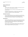
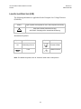
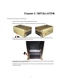
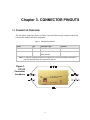
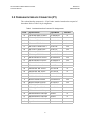
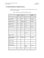
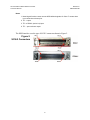
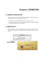
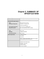
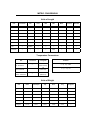
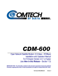
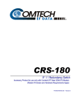
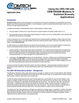
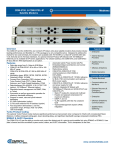
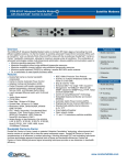
CIC-20 LVDS to HSSI
Interface Converter
Installation and Operation Manual
(Accessory Product for use only with Comtech EF Data CDM-600 Modems)
Part Number MN/CIC20.IOM
Revision 0
November 6, 2001
CIC-20 LVDS to HSSI
Interface Converter
Installation and Operation Manual
(Accessory Product for use only with Comtech EF Data CDM-600 Modems)
Comtech EF Data is an ISO 9001
Registered Company.
Part Number MN/CIC20.IOM
REVISION 0
November 6, 2001
Copyright © Comtech EF Data, 2001. All rights reserved. Printed in the USA.
Comtech EF Data, 2114 West 7th Street, Tempe, Arizona 85281 USA, (480) 333-2200, FAX: (480) 333-2161.
CIC-20 LVDS to HSSI Interface Converter
Preface
Revision 0
MN/CIC20.IOM
CUSTOMER SUPPORT
Contact the Comtech EF Data Customer Support Department for:
Product support or training
Information on upgrading or returning a product
Reporting comments or suggestions concerning manuals
Contact Customer Support using any of the following methods:
Mail:
Comtech EF Data
Email: [email protected]
Customer Support Department
Internet: www.comtechefdata.com
2114 West 7th Street
Tempe, Arizona 85281 USA
Phone: (480) 333-2200 (Main Comtech EF Data Number)
(480) 333-4357 (Customer Support Desk)
Fax:
(480) 333-2161
To return a Comtech EF Data product (in-warranty and out-of-warranty) for repair or
replacement:
1. Request a Return Material Authorization (RMA) number from the Comtech EF Data
Customer Support Department.
2. Be prepared to supply the Customer Support representative with the model number,
serial number, and a description of the problem.
3. To ensure that the product is not damaged during shipping, pack the product in its
original shipping carton/packaging.
4. Ship the product back to Comtech EF Data. (Shipping charges should be prepaid.)
For more information regarding the warranty policies, see Warranty Policy, p. ix.
ii
Table of Contents
CHAPTER 1.
INTRODUCTION ....................................................................................1
CHAPTER 2.
INSTALLATION .....................................................................................3
CHAPTER 3.
CONNECTOR PINOUTS .......................................................................5
3.1 Connector Overview ............................................................................................................... 5
3.2 Overhead Interface Connector (P1) ...................................................................................... 6
3.3 Data Interface Connector (J1) ............................................................................................... 7
CHAPTER 4.
OPERATION ..........................................................................................9
4.1 MODEM CONFIGURATION............................................................................................... 9
4.2 MODE SELECT...................................................................................................................... 9
CHAPTER 5.
SUMMARY OF SPECIFICATIONS .....................................................11
iii
CIC-20 LVDS to HSSI Interface Converter
Preface
Revision 0
MN/CIC20.IOM
Figures
Figure 1. CIC-20 Connector Locations ....................................................................................... 5
Figure 2. SCSI-2 Connectors........................................................................................................ 8
Figure 3. Switch Location............................................................................................................ 9
Tables
Table 1. External Connections .................................................................................................... 5
Table 2. Overhead Interface Connector Pin Assignments ....................................................... 6
Table 3. HSSI Pinout (J1) 50-Pin Mini-D/SCSI-2 Female........................................................ 7
iv
CIC-20 LVDS to HSSI Interface Converter
Preface
Revision 0
MN/CIC20.IOM
ABOUT THIS MANUAL
This manual provides installation and operation information for the Comtech EF Data
CIC-20 LVDS to HSSI Interface Converter. This is a technical document intended for
earth station engineers, technicians, and operators responsible for the operation and
maintenance of the CIC-20 LVDS to HSSI Interface Converter.
RELATED DOCUMENTS
Comtech EF Data CDM-600 Digital Satellite Modem Installation and Operation Manual
CONVENTIONS AND REFERENCES
CAUTIONS AND WARNINGS
Indicates information critical for proper equipment function.
IMPORTANT
CAUTION
Indicates a hazardous situation that, if not avoided, may result in minor or moderate
injury. CAUTION may also be used to indicate other unsafe practices or risks of
property damage.
Indicates a potentially hazardous situation that, if not avoided, could result in
death or serious injury.
WARNING
TRADEMARKS
All product names mentioned in this manual may be trademarks or registered trademarks
of their respective companies and are hereby acknowledged.
REPORTING COMMENTS OR SUGGESTIONS CONCERNING THIS MANUAL
Comments and suggestions regarding the content and design of this manual will be
appreciated. To submit comments, please contact the Comtech EF Data Customer
Support Department.
v
CIC-20 LVDS to HSSI Interface Converter
Preface
Revision 0
MN/CIC20.IOM
TELECOMMUNICATIONS TERMINAL EQUIPMENT DIRECTIVE
In accordance with the Telecommunications Terminal Equipment Directive 91/263/EEC,
this equipment should not be directly connected to the Public Telecommunications
Network.
EMC (ELECTROMAGNETIC COMPATIBILITY)
The CIC-20 LVDS to HSSI Interface Converter has been demonstrated, by independent
testing, to comply with the following standards:
Emissions:
EN 55022 Class B - Limits and methods of measurement of radio
interference characteristics of Information Technology Equipment.
FCC PART 15 CLASS B
Immunity:
EN 50082 Part 1 - Generic immunity standard, Part 1: Domestic,
commercial and light industrial environment.
In order that the CIC-20 LVDS to HSSI Interface Converter continues to comply with
these standards, observe the following instructions:
All 'D' type connectors attached to the unit must have back-shells which provide
continuous metallic shielding. Cable with a continuous outer shield (either foil or
braid, or both) must be used, and the shield must be bonded to the back-shell.
The equipment must be operated with its cover on at all times. If it becomes
necessary to remove the cover, the user should ensure that the cover is correctly refitted before normal operation commences.
vi
CIC-20 LVDS to HSSI Interface Converter
Preface
Revision 0
MN/CIC20.IOM
SAFETY COMPLIANCE
EN 60950
Applicable testing is routinely performed as a condition of manufacturing on all units to
ensure compliance with safety requirements of EN60950.
This equipment meets the Safety of Information Technology Equipment specification as
defined in EN60950.
The equipment is rated for operation at +12 volts DC and -12 volts DC. It has a
maximum power consumption of 2.0 watts. The power supply current is, in all
circumstances, supplied by a single Comtech CDM-600 Modem.
EQUIPMENT CONNECTION
The CIC-20 LVDS to HSSI Interface Converter is designed for operation ONLY with
Comtech CDM-600 modems. These modems supply DC operating current (electronically
fused and protected) and control signals for the correct functioning of this unit.
Connection to other manufacturer’s equipment could result in damage to the unit.
ENVIRONMENTAL
The CIC-20 LVDS to HSSI Interface Converter must not be operated in an environment
where the unit is exposed to extremes of temperature outside the ambient range 0 to 500C,
precipitation, condensation, or humid atmospheres above 95% RH, altitudes (unpressurised) greater than 2000 meters, excessive dust or vibration, flammable gases,
corrosive or explosive atmospheres.
Operation in vehicles or other transportable installations which are equipped to provide a
stable environment is permitted. If such vehicles do not provide a stable environment,
safety of the equipment to EN60950 may not be guaranteed.
vii
CIC-20 LVDS to HSSI Interface Converter
Preface
Revision 0
MN/CIC20.IOM
LOW VOLTAGE DIRECTIVE (LVD)
The following information is applicable for the European Low Voltage Directive
(EN60950):
<HAR>
Type of power cord required for use in the European Community.
CAUTION: Double-pole/Neutral Fusing.
!
ACHTUNG: Zweipolige bzw. Neutralleiter-Sicherung.
International Symbols:
Symbol
Definition
Symbol
Definition
Alternating Current.
Protective Earth.
Fuse.
Chassis Ground.
Note: For additional symbols, refer to “Cautions” listed earlier in this preface.
viii
CIC-20 LVDS to HSSI Interface Converter
Preface
Revision 0
MN/CIC20.IOM
WARRANTY POLICY
This Comtech EF Data product is warranted against defects in material and workmanship
for a period of two years from the date of shipment. During the warranty period, Comtech
EF Data will, at its option, repair or replace products that prove to be defective.
For equipment under warranty, the customer is responsible for freight to Comtech EF
Data and all related custom, taxes, tariffs, insurance, etc. Comtech EF Data is responsible
for the freight charges only for return of the equipment from the factory to the customer.
Comtech EF Data will return the equipment by the same method (i.e., Air, Express,
Surface) as the equipment was sent to Comtech EF Data.
LIMITATIONS OF WARRANTY
The foregoing warranty shall not apply to defects resulting from improper installation or
maintenance, abuse, unauthorized modification, or operation outside of environmental
specifications for the product, or, for damages that occur due to improper repackaging of
equipment for return to Comtech EF Data.
No other warranty is expressed or implied. Comtech EF Data specifically disclaims the
implied warranties of merchantability and fitness for particular purpose.
EXCLUSIVE REMEDIES
The remedies provided herein are the buyer's sole and exclusive remedies. Comtech EF
Data shall not be liable for any direct, indirect, special, incidental, or consequential
damages, whether based on contract, tort, or any other legal theory.
DISCLAIMER
Comtech EF Data has reviewed this manual thoroughly in order that it will be an easy-touse guide to your equipment. All statements, technical information, and
recommendations in this manual and in any guides or related documents are believed
reliable, but the accuracy and completeness thereof are not guaranteed or warranted, and
they are not intended to be, nor should they be understood to be, representations or
warranties concerning the products described. Further, Comtech EF Data reserves the
right to make changes in the specifications of the products described in this manual at any
time without notice and without obligation to notify any person of such changes.
ix
CIC-20 LVDS to HSSI Interface Converter
Preface
Revision 0
MN/CIC20.IOM
x
Chapter 1. INTRODUCTION
CIC-20
LVDS to HSSI
Interface Converter
While the CDM-600 modem is capable of data rates up to 20 Mbps, its many interfaces
do not include the HSSI format.
In order to accommodate the HSSI data formats and overhead, the CIC-20 converter
attaches to the rear of the modem at the 25-pin data connectors. No external power is
required and all settings are made on the CIC-20 using one switch.
1
CIC-20 LVDS to HSSI Interface Converter
Introduction
Revision 0
MN/CIC20.IOM
This page has been intentionally left blank.
2
Chapter 2. INSTALLATION
Perform the following procedural steps:
1
Power down the modem before installing the converter.
2
Remove the four screws, on the sides, and lift off the cover of the CIC-20.
3
The 25-pin female and male D-sub connectors includes four captive screws which can be
reached by removing the cover of the CIC-20.
4
Attach the CIC-20 to the CDM-600 modem by mating the two pair of 25-pin D-subs together,
then tighten the four captive screws.
5
Re-attach the cover and replace the four screws. The metal surfaces of the modem and CIC20 should be flush.
3
CIC-20 LVDS to HSSI Interface Converter
Installation
Revision 0
MN/CIC20.IOM
This page has been intentionally left blank
.
4
Chapter 3. CONNECTOR PINOUTS
3.1 CONNECTOR OVERVIEW
The rear panel connectors (shown in Table 1) provide all necessary external connections
between the modem and other equipment.
Table 1. External Connections
Name
Ref
Connector Type
Function
Overhead
P1
25-pin D (male)
Overhead Data
Data Interface
J1
50-pin, mini-D SCSI-II
Data Input/Output
HSSI (female)
Note: To maintain compliance with the European EMC Directive (EN55022, EN50082-1)
properly shielded cables are required for data I/O.
Figure 1.
CIC-20
Connector
Locations
5
CIC-20 LVDS to HSSI Interface Converter
Connector Pinouts
Revision 0
MN/CIC20.IOM
3.2 OVERHEAD INTERFACE CONNECTOR (P1)
The overhead interface connector is a 25-pin D male interface located on the rear panel of
the modem. Refer to Table 2 for pin assignments.
Table 2. Overhead Interface Connector Pin Assignments
Pin #
Signal Function
Signal Name
Direction
14
IDR 64 kbps ESC Tx Data +
TX-422DAT-B
In
2
IDR 64 kbps ESC Tx Data -
TX-422DAT-A
In
12
IDR 64 kHz ESC Tx Clock +
TX-422CLK-B
Out
15
IDR 64 kHz ESC Tx Clock -
TX-422CLK-A
Out
11
IDR 1 kHz Tx Octet Clock +
TX-OCT-B
Out
24
IDR 1 kHz Tx Octet Clock -
TX-OCT-A
Out
16
IDR 64 kbps ESC Rx Data +
RX-422DAT-B
Out
3
IDR 64 kbps ESC Rx Data -
RX-422DAT-A
Out
9
IDR 64 kHz ESC Rx Clock +
RX-422CLK-B
Out
17
IDR 64 kHz ESC Rx Clock -
RX-422CLK-A
Out
19
IDR 1 kHz Rx Octet Clock +
RX-OCT-B
Out
4
IDR 1 kHz Rx Octet Clock -
RX-OCT-A
Out
20
Balanced Ext. Ref. Clock +
EXT-CLK-B
In
23
Balanced Ext. Ref. Clock -
EXT-CLK-A
In
13
IBS ESC RS232 Tx Data
TX-232-DATA
In
22
IBS ESC RS232 Tx Clock
TX-232-CLK
Out
8
IBS ESC RS232 Rx Data
RX-232-DATA
Out
10
IBS ESC RS232 Rx Clock
RX-232-CLK
Out
5
IBS Tx High-Rate ESC Data
TX-ASYNC
In
6
IBS Rx High-Rate ESC Data
RX-ASYNC
Out
1
IDR Back Alarm 1 H/W input
BW-IN1
In
18
IDR Back Alarm 2 H/W input
BW-IN2
In
21
IDR Back Alarm 3 H/W input
BW-IN3
In
25
IDR Back Alarm 4 H/W input
BW-IN4
In
7
Signal Ground
Ground
-
6
CIC-20 LVDS to HSSI Interface Converter
Connector Pinouts
Revision 0
MN/CIC20.IOM
3.3 DATA INTERFACE CONNECTOR (J1)
The Data Interface connector is a 50-pin mini D SCSI-II, HSSI type female. Refer to
Table 3 for pin assignments.
Table 3. HSSI Pinout (J1) 50-Pin Mini-D/SCSI-2 Female
Signal Function
HSSI
EIA-613
Signal
Circuit
Signal Ground
SG
102
1, 26
Receive Timing
RT
115
2, 27
From DCE
DCE Available
CA
107
3, 28
From DCE
Receive Data
RD
104
4, 29
From DCE
Loopback Circuit C
LC
undefined
5, 30
Not used
Send Timing
ST
114
6, 31
From DCE
Signal Ground
SG
102
7, 32
DTE Available
TA
108/2
8, 33
To DCE
Terminal Timing
TT
113
9, 34
To DCE
Loopback Circuit A
LA
143
10, 35
Not used
Send Data
SD
103
11, 36
To DCE
Loopback Circuit B
LB
144
12, 37
Not used
Signal Ground
SG
102
13, 38
Reserved (to DCE)
Pin # (+, -)
Circuit
Direction
14,15,17, 18,
39 - 43
Not used
From DTE
Tx_Carrier_Off_L
(Notes 1 and 3)
CO
undefined
16
Signal Ground
SG
102
19, 44
Carrier Detect (lock)
(Notes 1 and 2)
CD
undefined
20
From DCE
Mod Fault
(Notes 1 and 4)
MF
undefined
21
From DCE
Demod Fault
(Notes 1 and 4)
DF
undefined
45
From DCE
Unit Fault
(Notes 1 and 4)
UF
undefined
46
From DCE
22-23
Not used
Reserved (to DTE)
47-48
Test Mode
TM
142
24, 49
Signal Ground
SG
102
25, 50
7
Not used
CIC-20 LVDS to HSSI Interface Converter
Connector Pinouts
Revision 0
MN/CIC20.IOM
Notes:
1. Noted signal function names are non-HSSI defined signals. On Cisco™ routers there
is no connection to those pins.
2. TTL - output.
3. TTL or RS232 (active low) input
4. TTL – open collector output.
The HSSI interface uses the type of SCSI-2 connector shown in Figure 2.
Figure 2.
SCSI-2 Connectors
8
Chapter 4. OPERATION
4.1 MODEM CONFIGURATION
After applying power to the modem, the following configuration changes must be made
to the modem in order for it to operate with the CIC-20.
1
Program the transmit and receive data rates to what is desired for Tx and Rx.
2
Set the data interface type to LVDS. The modem itself operates in this electrical format while
the converter translates between LVDS and HSSI.
4.2 MODE SELECT
The dip switch (S2) selects the functionality of the control signals, CA and TA. It can be
accessed with a small screwdriver. The OFF (down) position is the default. Switch S1 is
not used.
Dip Switch S2
ON (Up)
TA CONTROLS TX CARRIER
RR CONTROLS CA
OFF (Down)
TA TO CA LOOP
Figure 3.
Switch Location
9
CIC-20 LVDS to HSSI Interface Converter
Operation
Revision 0
MN/CIC20.IOM
This page has been intentionally left blank.
10
Chapter 5. SUMMARY OF
SPECIFICATIONS
Equipment Type
LVDS / HSSI Interface Converter
Modems Supported
Comtech EF Data CDM-600 Digital Satellite Modems
Terrestrial (User) Data Interface:
Type
HSSI (synchrounous serial)
HSSI Signals Supported
RT, RD, ST, TT, SD, TA, CA,
Per EIA-612 (10KH ECL)
Other Signals Supported
CD, DF, MF, TX_CARRIER_OFF
Electrial Connector
50-pin mini-D female per EIA-613 (HSSI)
Modem Data Interface
Type
LVDS, Serial
Data Rate:
2.4 kbps to 20.0 Mbps
Electrical Connector
25-pin D male
Power Requirements
2.0 Watts maximum
+12 volts DC
-12 volts DC
(Power is supplied by the Modem. These power supplies
are electronically fused and protected.)
Approvals
‘CE’ as follows:
EN 55022 Class B (Emissions)
EN 50082-1 (Immunity)
EN 60950 (Safety)
FCC Part 15 Class B
11
CIC-20 LVDS to HSSI Interface Converter
Specifications
Revision 0
MN/CIC20.IOM
This page has intentionally left blank.
12
METRIC CONVERSIONS
Units of Length
Unit
Centimeter
Inch
Foot
Yard
Mile
Meter
Kilometer
Millimeter
1 centimeter
—
0.3937
0.03281
0.01094
6.214 x 10⁻⁶
0.01
—
—
1 inch
2.540
—
0.08333
0.2778
1.578 x 10⁻⁵
0.254
—
25.4
1 foot
30.480
12.0
—
0.3333
1.893 x 10⁻⁴
0.3048
—
—
1 yard
91.44
36.0
3.0
—
5.679 x 10⁻⁴
0.9144
—
—
1 meter
100.0
39.37
3.281
1.094
6.214 x 10⁻⁴
—
—
—
1 mile
1.609 x 10⁵
6.336 x 10⁴
5.280 x 10³
1.760 x 10³
—
1.609 x 10³
1.609
—
1 mm
—
0.03937
—
—
—
—
—
—
1 kilometer
—
—
—
—
0.621
—
—
—
Temperature Conversions
° Fahrenheit
Unit
° Centigrade
Formulas
0
—
C = (F - 32) * 0.555
(water freezes)
32° Fahrenheit
100
—
F = (C * 1.8) + 32
(water boils)
212° Fahrenheit
273.1
—
(absolute 0)
-459.6° Fahrenheit
Units of Weight
Gram
Ounce
Avoirdupois
Ounce
Troy
Pound
Avoir.
Pound
Troy
Kilogram
—
0.03527
0.03215
0.002205
0.002679
0.001
1 oz. avoir.
28.35
—
0.9115
0.0625
0.07595
0.02835
1 oz. troy
31.10
1.097
—
0.06857
0.08333
0.03110
1 lb. avoir.
453.6
16.0
14.58
—
1.215
0.4536
1 lb. Troy
373.2
13.17
12.0
0.8229
—
0.3732
1 kilogram
1.0 x 10³
35.27
32.15
2.205
2.679
—
Unit
1 gram
2114 WEST 7TH STREET TEMPE ARIZONA 85281 USA
480 • 333 • 2200 PHONE
480 • 333 • 2161 FAX