1
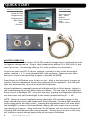
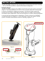
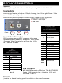
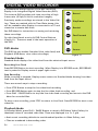
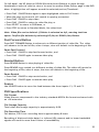
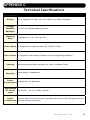
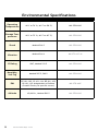
N
W
MARINE PC
E
S
MPC-ML10DVR
Digital Video Recorder
LCD Monitor
User Manual
www.MarinePC.com
Owner Record
Here is an easy-to-locate form to record the unit’s serial number, and from the invoice,
record the invoice date. The unit’s serial number is located on the back panel.
If the unit ever requires service, please refer to this information when contacting the
MarinePC Service Center.
Product
Serial Number
Invoice Date
____ / ____ / ____
MPC-ML10DVR
w w w. m a r i n e p c . c o m
Information Disclaimer
This MarinePC User Manual is provided “as-is”, without warranty of any kind, either expressed or implied, including but not limited to the implied warranties or merchantability and fitness for a particular purpose.
Documentation Change Notice
The information in this User Manual is subject to change without prior notice in order to improve readability and
reliability as well as design and function. These changes shall be incorporated in a new revision, available from
the product and/or download section of the MarinePC web site, www.marinepc.com.
Liability
In no event shall MarinePC be liable for direct, indirect, special incidental or consequential damages arising out
of the use of or the inability to use MarinePC’s product or its documentation, even if advised of the possibility of
such damages.
Endorsement
Product names mentioned herein are used for identification purposes only and may be trademarks and/or registered trademarks of their respective companies.
Copyright
This document contains proprietary information protected by copyright. All rights are reserved. No part of this
manual, in whole or part, may be reproduced by any means, in any form, without prior written permission of
MarinePC.
2
MPC-ML10DVR-UM(B) 4/2011
MPC-ML10DVR
Military Grade
Digital Video Recorder
LCD Monitor
User Manual
www.MarinePC.com
MPC-ML10DVR-UM(B) 4/2011
3
Table of Contents
Introduction..........................................................5
Quick Start Guide...................................................6
NVIS Option..........................................................9
Safety................................................................ 10
Product Care and Maintenance................................ 12
System Set-up..................................................... 13
Installation......................................................... 14
Display Connections.............................................. 16
Operator Controls................................................. 17
On-Screen Display................................................ 18
Digital Video Recorder........................................... 24
Video Gallery...................................................... 26
Appendix A - Overview Drawings.............................. 27
Appendix B - Troubleshooting.................................. 27
Appendix C - Technical Specifications........................ 29
4
MPC-ML10DVR-UM(B) 4/2011
Welcome.
With the acquisition of an All-Weather Digital Video Recorder/Monitor, MPC-ML10DVR,
we welcome you to MarinePC’s family of ruggedized professional marine grade products.
You will soon become familiar with the quality difference in this bright sunlight-readable (~1 nit to 1,000 nits) Monitor, specifically designed to meet or exceed MIL-Specs for
use in harsh marine environments. MarinePC has incorporated the latest LED backlighting to increase brightness and super-low dimming without increased heat, and extends
temperature, shock and vibration specifications.
The MPC-ML10DVR also integrates full DVR capability directly inside the case of the waterproof monitor, eliminating separate mounting interconnecting cables, saving space
and providing environmental protection and tranportability for the DVR.
The MPC-ML10DVR handles a wide-range of severe environments, making it the first
choice of serious mariners for their demanding applications. Designed to be rugged,
the 800x600 (SVGA) Resolution Flat Panel Display is engineered to mate perfectly to all
leading edge cameras including infrared, image amplified and visible spectrum sources.
Housed in a milled billet aluminum case, the slim-profile MPC-ML10DVR is light weight
and watertight, with fully sealed (IP67) case and standard MIL-C-38999 connectors.
Engineered to be energy efficient to conserve power, the MPC-ML10DVR has three
Composite Video inputs, with a source select button that lets you easily move between
up to three inputs, and also provides one video output. Recorded files can be easily
downloaded in standard .wmv file format via a USB connection.
Our MarinePC Service and Support Team is prepared to assist you – we are MarinePC.
MPC-ML10DVR-UM(B) 4/2011
5
QUICK START
Monitor Functions
DVR Functions
Power On-Off
Brightness Up
Brightness Dn
OSD Select
Next
Previous
Record On-Off
Play - Pause
Rewind
Fast Forward
Stop
Source Select
MONITOR OPERATION
Terminate Positive cable lead to 10-36 VDC positive voltage source and Negative lead
to negative voltage source. Plug in cable (supplied by Marine PC or FBO) into J1 and
turn CW to lock. (Connecting cable to J2 is only necessary for download.)
Connect at least one RS-170 device (camera, typically) to any of the three input
cables, marked 1, 2, 3, using standard BNC coax connector. Make sure the video
device is turned on and providing a signal to the MPC-ML10DVR.
Press Power On-Off Button once to turn on unit. After a few seconds of a power up
routine, the first operational signal being received will be displayed. The LED backlight will automatically come on at about half brightness.
Adjust brightness by repatedly pressing the Brightness Up or Down button. Adjust to
the lowest setting which still allows ease of viewing. The last step of the Brightness
Down control is Backlight OFF. From this last step, pressing the Brightness Up button
one short time will put the backlight in the lowest possible setting of ~ 1 nit.
NOTE: Using the lowest brightness setting (backlight off) maintains power to the
other internal electronics and keeps them fully functional, including DVR recording,
while saving power and night vision. Pressing the brightness button will then allow
the backlight to come on and immediately display the video input and any recording function in progress. Using the Power On-Off button will turn off all electronics,
including DVR recording and the video processor. Turning the unit back on this way
will initiate a several second delay while all electronics initializes.
6
MPC-ML10DVR-UM(B) 4/2011
Selecting Video Sources
If more than one video device is connected and operational, selection of the video
source to be displayed on the LCD is made by pressing the button located on the lower
right of the MPC-ML10DVR. If two sources are present, pressing this button will switch
from one source to the other. If three sources are present, pushing this button will
successively display one, then the next and the next and then back to the original
source. The numbering of the input channels indicates the sequence of the selection
process.
Recording Video
The integrated full function DVR in the MPC-ML10DVR will record whatever is being
displayed on the LCD. If there is no active input, the DVR will not function. To start
recording, simply press the top right button marked REC. You will notice a RECORDING
message will be displayed in the upper right margin of the LCD to indicate recording
is in progress (this will not appear in the recorded file). A .wmv file with a sequenced
filename will be initiated including time and date information, and will continue to
capture whatever information is being displayed. If sources are switched, the DVR
will continue to record through the switch. The length of the file is indeterminate. To
stop recording, simply press the REC button again and the file will be closed and saved,
and the RECORDING message will disappear from the display. Alternately, pressing the
Stop button, marked with a square, will also stop the recording. This process can be
repeated any number of times, each time creating a unique .wmv file. Any number
of files can be created. A total of 8 hours of files can be recorded. If the solid state
memory storing the files is already full, the DVR will start to overwrite the existing files
starting with the oldest file.
VIDEO PLAYBACK
After stopping a recording, or at any other time when recording is not taking place,
any video file can be played back in the MPC-ML10DVR. To review any saved file,
simply press the Play-Pause button, second down on the right. The currently displayed
video input on the LCD will be replaced by the gallery, a list of thumbnail images of
sequentially numbered files. The last file saved will have the highest number and
be highlighted when entering this list. To select any previously saved file, press the
PREVIOUS button on the lower left. Press once to move back in sequence one at a
time. Use the NEXT button above the Previous button to move forward. To play back
the highlighted file, press the Play-Pause Button once to open this file, and press again
to play file from the beginning. Press again to Pause, press again to resume play. (TIP:
To speed the process from Record to Playback, simply pressing the Play button during a Recording will automatically stop and save the file and put up the thumbnail file
display with the just stopped file hightlighted.)
MPC-ML10DVR-UM(B) 4/2011
7
FAST FORWARD - REWIND
While the file is being played, the file can be fast searched by using the middle two
buttons on the right side. The file will then be advanced or played backward at
double of normal speed.
TIP: In order to facilitate quickly locating the images to be reviewed, it is highly
recommended not to just turn on the record function and let it go continuously.
Rather, it is very much more useful to record many smaller files rather than one or
two enormous files.
DELETE FILE
Any selected file can be permanently deleted in the unit to remove unwanted files.
This will recover storage space and time for more recording. In the Playback mode,
note the Select button on the left side has been repurposed and the display will
show a DELETE FILE message. Press the Delete File button once, and the Display will
ask you to confirm this action and require a response of YES or NO using the Previous
and Next buttons.
Caution!
Once YES is selected, the file will be PERMANENTLY and
IRREVOCABLY DELETED!!!!
LIVE DISPLAY
To return the display to the live video input from the selected source, press the Stop
button, which now has the LIVE FEED message. The MPC-ML10DVR now is displaying
live video. Sources can be switched and new Recorded files can be created.
DOWNLOADING FILES
To download files, an auxilliary USB cable must be attached to the MPC-ML10DVR.
The cable can be attached to any PC for standard Windows file transfer of the
stored .avi files in the unit to the computer. Once the cable is connected, press
the Play button. The Fast Forward button on the right side now has the DOWNLOAD message shown on the display. Press this button and the unit will now be
recognized by the PC as a memory device, much like a USB stick. Files can now
be either copied or moved from the MPC-ML10DVR to a file folder in the PC. It is
recommended in most cases that the files be moved in order to free up storage for
the next use. The process of transferring the files may take some time depending
upon the number and size of the files being transferred. Once stored in the PC, any
commercially available video player capable of processing files created with MPEG-4
compression (Windows Media Player, for example) can open and play the files. After
the download process is complete, remove the USB cable from the PC and press the
Stop button to return to Live Feed.
(NOTE: file transfers can ONLY be made from the MPC-ML10DVR to a computer.
The storage in the MPC-ML10DVR is permanently write protected through the USB
connection so that no external files or unwanted data can be introduced into this
storage.)
8
MPC-ML10DVR-UM(B) 4/2011
NVIS Option
Overview
The MPC-ML10DVR is often used as a display for low light and infrared cameras for operations at
night. Operator situational awareness can be further enhanced with the use of Night Vision Goggles or Monoculars, commonly referred to as NVG’s. These devices amplify available light within
a certain spectrum to allow visualization of objects that are otherwise undetectable. At normal
display light levels, if the operator would look at the display through the NVG’s, the brightness
may cause them to “bloom” or become over-driven and momentarily blind the operator. The
brightness of the MPC-ML10DVR can be turned down to the very lowest setting and allow for direct use with Generation 1 & 2 NVG’s. For high amplification common with GEN3 NVG’s, even this
very low light is too much. To prevent this over-driving, NVIS “Green” compatible backlighting option is available that will limit the light used to backlight the display to frequencies not amplified
by the NVG’s, thereby allowing both those using NVG’s and those viewing normally to look at the
display. Alternately, some situations require the use of red spectrum lighting to preserve natural
night vision. As an option, the MPC-ML10DVR can be configured with NVIS “Red”to allow for use
in this environment The NVIS Option makes either mode of operation available to the operator
through a single button action.
NVIS Green / Red OSD Setup
After pressing Select to enter the OSD, Select Tools, then select either NVIS Green or NVIS Red.
Once saved in the OSD, the UP / DOWN AROW Buttons will allow the operator to toggle between
that selection (Green or Red) and Day Mode. (NOTE: both NVIS colors are not available at the
same time.)
The Display will now automatically power on in NVIS mode. Daylight mode can be displayed by
pushing the UP ARROW Button. To return to NVIS Mode., push the DOWN ARROW button.
To Deselect the NVIS Option, reenter the OSD Select NVIS anddisable NVIS ON PWR.
MPC-ML10DVR-UM(B) 4/2011
9
Safety
General Safety Instructions
• Before operating the MPC-ML10DVR Monitor, read this User Manual thoroughly
• Retain this User Manual for future use
• Verify the computer system capability (see System Set-up) to insure operation of the
Monitor
• For expeditious installation, follow these User Manual instructions in the sequence
presented
• Adhere to all Caution and Warnings on system parts and as stated in this User manual
• All User Manual instructions for installation and operation must be followed precisely
• Adjust only those controls covered by the User Manual’s operating instructions; im-
Safety Icons
Warning! Shock Hazards
warning!
This icon is intended to tell you of a potential risk of electrical shock.
Caution! Instructional
caution!
This icon is intended to tell you of important operating and/or
maintenance instructions.
General Unit Safety
• Always disconnect the unit from the power source before cleaning
• Do not operate the unit with a damaged cord
• Do not operate if the unit has been dropped or damaged. The unit needs inspected by
qualified MarinePC Service Personnel
• Position the power cord so it shall not be in contact with hot surfaces
• Do not allow anything to rest on the power cord, and
• Do not place the power cord where there shall be foot traffic.
General Safety Precautions
warning!
• Power cord must be connected to a properly wired and grounded power source
• Any equipment to which the unit shall be attached must also be connected to properly
wired and grounded power sources
• Do not connect or disconnect the unit during an electrical storm
• Do not remove the unit covers – there are no user serviceable parts in the unit
• Do not disassemble or modify the unit to avoid the possibility of electrical shock,
damage to electrical components or scratching the Display surface, and
• Disassembly of the unit voids the warranty.
Fluids from LCD Display
caution!
• If the Monitor should ever become shattered, do not touch fluids from an LCD Display
• If fluid should get on hands or clothing, immediately wipe off with liquid soap or rubbing
alcohol; wash with water; consult with a doctor, and
• If fluid gets in the eyes, flush eyes immediately with water for a minimum of 15 minutes;
consult with a doctor.
10 MPC-ML10DVR-UM(B) 4/2011
EMI/RFI
Caution!
Product has been engineered to meet or exceed international industry standards addressing product design and enclosure protection against EMI/RFI. For
compliance with specific MIL-STD-461E standards, please consult factory.
Electrical
Connecting Cables
• Disconnect power to computer when Display is being installed
• Upon installation, verify power input connector is securely seated on Display
• Position power cable so it is not in contact with hot surfaces
• Do not allow anything to rest on power cable, and
• Protect power cable from extreme heat sources.
Power Source
• Always connect to a properly grounded DC (standard) power source
• Any equipment to which Display is attached must also be connected to properly wired
and grounded power sources
• Input voltage is 10 - 36 VDC
Power Consumption
Warning!
MPC-ML10DVR power consumption is listed at 6 watts minimum - 20 Watts maximum.
Protection on Servicing
Servicing - User
• User Servicing is limited to cleaning the Display
• Do not disassemble or modify the Display to avoid the possibility of electrical shock,
damage to its electrical components or scratching the Display surface, and
• Disassembly voids the warranty.
Servicing - Marine PC
Marine PC Qualified Service Personnel may be required to service the Display if:
• Does not operate normally when installation instructions are followed
• Does not operate normally when operating instructions are followed
• Has been dropped or damaged, or
• Exhibits a distinct change in performance, indicating a need for service.
Shipping
If Display should need to be shipped to the MarinePC Service Center, the original packing
material should be used to insure safety of Display in shipping. Repack Display as it
would have originally been received from MarinePC.
MPC-ML10DVR-UM(B) 4/2011
11
Product Care and maintenaNCE
Product Care
This MPC-ML10DVR Monitor has been designed to provide optimum performance and service without any required scheduled maintenance other than occasional cleaning.
warning!
caution!
Turn off the Monitor power before cleaning the Monitor screen, or unit’s enclosure.
• Do not use abrasive cleaners or solvent-based (flammable) cleaners on the
Flat Panel or Touch Screen Display, its enclosure or any other electrical device
(cables, power cord, etc)
• Do not use paper products as they may scratch the Display screen, and
• Do not directly apply cleaning solutions to the Display screen.
Display Screen Cleaning
• A vinegar-based cleaner is preferred to prevent streaking and degradation of the
coatings, or
• A non-abrasive glass cleaner such as a professional foam glass cleaner
• Apply the cleaning solution to a soft clean cloth, dampening slightly
• Keep a fresh side of the cleaning cloth towards the screen surface to avoid
scratching it with accumulated grit, and
• To minimize the risk of abrasion to the screen, air drying is recommended.
Monitor Enclosure
• Clean the unit enclosure with a soft clean cloth lightly dampened with a
general purpose mild detergent solution
• To rinse, wipe down with clean water, and
• Dry with a soft clean cloth.
In marine or similar environments,
an added benefit of a vinegar-based
cleaner is its effectiveness in
dissolving salt deposits.
Long-term Storage
• For long-term storage, it is suggested the unit be stored in a normal indoor environment and the Display glass be protected from accidental damage.
• For pedestal mount units, disconnect the cable(s) and loosen the arm adjustment to a
point where the ball can be removed from the arm, or
• For Flush or Panel Mount units, cover the product with a protective covering that shall
not scratch or transfer any dyes to the Display screen.
warning!
12 To avoid risk of electrical shock, do not disassemble the unit’s enclosure. Users
cannot service the Monitor. User maintenance is restricted to cleaning, as explained.
Disassembling the unit voids the warranty.
MPC-ML10DVR-UM(B) 4/2011
Maintenance
warning!
Power Cord
To avoid shock and fire hazards, replaced the unit’s power cord if:
• Insulation becomes damaged, or
• A loose connection is suspected.
Other Maintenance
Only MarinePC Qualified Service Personnel shall perform all maintenance except for the
repair or replacement of external cables.
SYSTEM SET-UP
System Requirements
The MPC-ML10DVR accepts a standard NTSC composite video signal from any device – a
camera, DVD or VCR.
Shipping Box Contents
The MPC-ML10DVR is shipped in a custom box with custom packaging. It is recommended that the installer should save box and all packaging materials in case Display should
need to be returned to the MarinePC Service Center.
Shipping box contents are:
• MPC-ML10DVR Display
• Mounting Hardware (For RAM or Surface Mount Only)
• User Manual
• Optional Cables (if Ordered)
MPC-ML10DVR-UM(B) 4/2011
13
Installation
The MPC-ML10DVR is designed to be mounted with a universal ball-and-socket mounting
kit, in a Flat Panel position or optional Flush Mount configuration.
Pedestal Mount
The MPC-ML10DVR is shipped with a RAM® universal ball-and-socket system mounting kit
(Figure 2). By installing Display with this kit, User can quickly adjust the viewing angle
to improve viewability in changing environments. This ball-and-socket system has
proven to be successful in supporting an extreme amount of weight in high vibration
and difficult-mount applications. Visit www.marinepccom for product mounting diagrams.
Locate the ball-and-socket system in shipping box. This kit consists of two RAM balls
on mounting plates and a RAM arm, with an adjustable T-knob and a packet of three
(3) M4 x 10 counter-sunk stainless screws for mounting. (Figures 2 - 4)
Mounting Holes
Figure 2
Ball and
Socket
Mount Only
Panel
Mount Only
Figure 3
14 MPC-ML10DVR-UM(B) 4/2011
Figure 4
There are three mounting holes in the center-back of Display for the ball mounting plate.
Take care not to strip screw holes or over tighten. (Figure 4)
• Note location of three mounting holes on a ball mounting plate (Figure 4)
• With three (3) M4 x 10 counter-sunk stainless screws attach this mounting plate to
back of the MPC-ML10DVR
• Mount second ball mounting plate where Display will be installed
• Insert each ball into RAM arm
• Lightly tighten arm around balls using T-knob on arm (Figure 2, 4)
• Adjust Display to viewing preference, and
• Tighten T-knob to hold Display in position.
It is recommended the remaining ball be mounted on a flat surface. Because of various
surface substrates Display will be mounted on, installer will provide screws to mount
other ball.
Panel Mount
Panel Mount installation should be specified at time of
order; the ball-and-socket mount system will not be
included in the shipping box. (Figure 5)
For installation, there are four tapped mounting holes
on four corners of the Display’s rear panel. Mounting
hardware packet is included with product accessories
in the shipping box. This packet includes four (4) M4
stainless steel threaded studs, 7.6 cm (3” long), four
(4) Nylock self-locking nuts and four (4) flat washers.
It is recommended installer refers to mount drawings
on MarinePC’s web site, (www.MarinePC.com), for exact
measurements. These drawings should be helpful
when installer cuts the required opening for the
Panel Mount installation.
Caution!
Figure 5
Take care not to strip screw holes or over tighten as the enclosure is aluminum.
MPC-ML10DVR-UM(B) 4/2011
15
Display Connections
Cables
Cables may be supplied by end user. Use the pinout guide below for fabrication.
Connectors
Connectors are located on bottom of Display housing, from left to right: Power / Video
Input and USB Input. (Figure 6).
Connectors are physically unique to insure installer makes correct connections.
J1Power / Video Input
J2USB Input
Power & Video
13 pin PLUG
MIL-DTL-38999 Series I
J1
Figure
J2
GND
SIGNAL
PIN
Power / Video Connector
TVR-V accepts a standard NTSC composite video signal
from an assortment of devices. The MIL-DTL 38999 Series
1 Power and Video Connector has a 13 pin plug. J1 Pinout is indicated in Table 1.
USB
4 pin PLUG
MIL-DTL-38999 Series I
PIN
SIGNAL
1
RS-170 (3) SIGNAL
2
RS-170 (3) GND
3
RS-170 (2) SIGNAL
4
RS-170 (2) GND
5
RS-170 (1) SIGNAL
6
RS-170 (1) GND
7
+28 VDC
8
+28 VDC
9
-28 VDC GND
10
-28 VDC GND
11
CHASSIS
12
RS-170 OUT SIGNAL
1
+5VDC
13
RS-170 OUT GND
2
USBD -
AMPH
88-569722-35P
3
USBD+
MATE
MS27467E11B35S
GND
STRAIN
M85049/49-2-10W
4
AMPH
71-533721-04P
MATE
MS3116F8-4S
STRAIN
Included
Table 2
Ground
Table 1
USB Connector
MPC-ML10DVR accepts a USB signal. The MIL-DTL 38999
Series 1 USB Connector has a 4 pin plug. J2 Pin-out is
indicated in Table 2.
A location for chassis bonding ground is available on the rear of enclosure.
16
MPC-ML10DVR-UM(B) 4/2011
Operator controls
On left hand side of Display bezel are six (6)
Operator Control Buttons (Figure 7).
Power On/Off
These Buttons are used in the basic operation
of the Display as well as when using the the
Digital Video Recorder (DVR) (See Digital Video
Recorder for instructions).
Brightness (Increase)
Brightness (Decrease)
Power ON/OFF Button
Select
• Power ON/OFF Button is identified with a
circle cut with a vertical slash
• Press and release to turn Display’s backlight
ON or OFF only, and
• Blue LEDs glow behind Buttons when
Display is powered on.
Up
Down
Figure 7
Brightness Controls Buttons
Brightness Control Buttons control Display Brightness. Upon unit power up, factory default is at maximum brightness.
• LARGE SUN Button: when repeatedly pressed or held down will cause the
Display’s backlight brightness to step up in increments to its brightest setting
• SMALL SUN Button: when repeatedly pressed or held down will cause the
Display’s backlight brightness to step down in increments to its lowest setting,
• Control’s lowest setting is near total black making it suitable in very subdued light, as
in night time operations, and
• Adjusted settings are maintained during power cycles (ON/OFF Button), and
• Brightness Settings return to factory default at main power recycle.
Select Button
The SELECT Button is used to access the OSD Menu.
Up Arrow Button
The UP Arrow Button is an adjustment or decision choice.
Down Arrow Button
The DOWN Arrow Button is an adjustment or decision choice.
MPC-ML10DVR-UM(B) 4/2011
17
On-screen display
The On-Screen Display (OSD) User Interface is where display adjustments are made. With
its user-friendly graphical interface, the OSD Menu provides access to fine-tuning the
Display according to the User’s preferences.
OSD Menu Activation
To activate the OSD menu, press and release SELECT Button.
Note: OSD Menu closes after 30 seconds of inactivity. This setting may be adjusted in the OSD
Menu: Tools: OSD Timeout.
OSD Menu Categories
The OSD Menu is comprised of five icons and an Exit Button; each icon represents a distinct menu category with its corresponding functions. (Figure 8)
Note: OSD Menu selections are indicated by icon only; there is no text.
IMAGE
INPUT
SELECTION ENHANCEMENT
COLOR
IMAGE
SETTINGS
TOOLS
EXIT
Figure 8
General Operating Instructions
• To open the OSD Menu, press (once) the SELECT Button
• OSD Menu appears across bottom of Display screen;
• Use UP or DOWN Button to move across Menu; selected icon turns yellow (Figure 9)
INPUT
IMAGE
SELECTION ENHANCEMENT
COLOR
IMAGE
SETTINGS
TOOLS
EXIT
Figure 9
• As Main Menu icon is highlighted, its Submenu appears in OSD dialog box
• Press (once) SELECT Button to enter selected Main Menu icon Submenu screen
• A highlight bar is superimposed over the first menu item
• Press UP or DOWN Button to move the highlight bar through the Submenu
• Press (once) SELECT Button to activate the highlighted Submenu item
• To Change values: press UP or DOWN Buttons, which increases (UP) or decreases
(DOWN) the value of the parameter as indicated in OSD dialog box; hold Button down
18 MPC-ML10DVR-UM(B) 4/2011
• Press (once) SELECT Button to go to a new menu item (Figure 10), or
• Press (once) SELECT Button to save new value or wait for OSD to timeout; it will autoclose, saving all changes
• To choose another menu item, use UP or DOWN Button to move across Main Menu;
repeat instructions, and
• To Exit, use UP or DOWN Button to move across OSD Menu to highlight Exit Sign icon;
press (once) SELECT Button to Exit; upon Exit, all changes are saved.
Sharpness
33
Black Level
50
Contrast
50
Exit
Figure 10
Saving Changes
• The Exit Button saves adjustments made to the OSD then exits the
Menu, or
• If the OSD times out, any adjustments made will automatically be
saved, then the Menu closes.
Caution!
OSD Menu Categories
Input Selection
The Input Selection Menu enables a selection of three Composite video input signals. Selection is based on Display configuration and its dependency upon a specific signal source.
Main power recycle resets input source to default, C Video 1 (Composite).
Note: The SOURCE Button on the Display allows for moving through various video input signals
without accessing the OSD Menu.
C Video 1
Select for first Input Signal. Select Exit Button to save.
C Video 2
Select for second Input Signal. Select Exit Button to save.
C Video 3
Select for third Input Signal. Select Exit Button to save.
Exit
Select Exit Button to save changes and exit from OSD Menu.
MPC-ML10DVR-UM(B) 4/2011
19
Image Enhancement
The Image Enhancement Menu enables adjustments of Image Enhancement values.
Sharpness
Select Sharpness to adjust Sharpness of displayed image. Use UP (right) or DOWN (left)
Button to adjust in preset increments. Select Exit to save.
Composite input signal factory default is 33 within a range of 0 - 100.
Black Level
Select Black Level to adjust Black Level of input Composite Signal. Factory default is 50
within a range of 0-100. Use UP (increase) or DOWN (decrease) Button to adjust in individual increments. Select Exit Button to save.
Contrast
Select Contrast to adjust difference in brightness between light and dark areas of Display
pixels. Factory default is 50 within a range of 0 - 100. Use UP (increase) or DOWN (decrease) Button to adjust in individual increments. Select Exit Button to save.
Exit
Select Exit Button to save changes and exit from OSD Menu.
Color
The Color Menu enables adjustments of Color Parameters of the Display image.
Composite Input Signal
Hue
Select Hue to adjust shading (gradation) within colors. Factory default is 50 within range
of 0 - 100. Use UP (increase) or DOWN (decrease) Button to adjust in individual increments. Select Exit Button to save.
Saturation
Select Saturation to adjust intensity or vividness (saturation) of color. Factory default is
50 within range of 0 - 100. Use the UP (increase) or DOWN (decrease) Button to adjust in
individual increments. Select Exit Button to save.
20
MPC-ML10DVR-UM(B) 4/2011
Color Reset
Select Color Reset to reset active Composite signal Color parameters Hue and Saturation
to factory default values (50). Select Exit Button to save.
Note: Color parameters will reset active Composite Video Input Signal only.
Exit
Select Exit Button to save changes and exit from OSD Menu.
Image Settings
The Image Setting Menu enables Display screen adjustments if Display is set-up for a VGA
Input Signal.
Note: Composite: Icon will be grayed, as it is unavailable.
Tools
The Tool Menu enables adjustment of miscellaneous parameters.
OSD Timeout
Factory default OSD Timeout setting is 30 seconds. Interval selections are Off, 5, 15, 30
and 60 seconds. Select to adjust time elapse between last Menu activity and when Menu
exits. Use the UP (increase) or DOWN (decrease) Buttons to change the values. Select
Exit Button to save.
Note: Any changes made in will be saved upon Timeout Exit.
MPC-ML10DVR-UM(B) 4/2011
21
Set Date and Time
Select Set Time to set-up Time (military) and Date stamp for Digital Video Recordings. Wait
for DVR to cycle to DATE / TIME set screen.
Set Date
Display will read a Date format of Year / Month / Day (2007/01/01)
• Use UP or DOWN Arrow Button to move through Date format (Year, Month, Day)
• Press SELECT to go into Active Mode to change format; note highlighted spaces
• Use UP or DOWN Arrow Button to set current Year
• Press SELECT to go into Inactive Mode
• Use UP or DOWN Arrow Button to move to Month; Months are highlighted
• Press SELECT to go into Active Mode
• Use UP or DOWN Arrow Button to set current Month
• Press SELECT to go into Inactive Mode
• Use UP or DOWN Arrow Button to move to Days; Days are highlighted
• Press SELECT to go into Active Mode
• Use UP or DOWN Arrow Button to set current Day
• Press SELECT to go into Inactive Mode
• Use UP or DOWN Arrow Button to move to Time
Set Military Time
Set Time (Military)
• Press SELECT to go into Active Mode
• Use UP or DOWN Arrow Button to set current Hours (Military)
• Press SELECT to go into Inactive Mode
• Use UP or DOWN Arrow Button to move to Minutes
• Press SELECT to go into Active Mode
• Use UP or DOWN Arrow Button to set current Minutes
• Press SELECT to go into Inactive Mode
• Use UP or DOWN Arrow Button to move to Seconds
• Press SELECT to go into Active Mode
22 MPC-ML10DVR-UM(B) 4/2011
• Use UP or DOWN Arrow Button to set current Seconds
• Press SELECT to go into Inactive Mode
When set, find EXIT dialog on right hand of Display screen by STOP Button
• Select STOP Button to Save and Exit the Date / Time Settings
• Display returns to default screen; to return to Tools, go to SELECT > Arrow to Tools >
Select to enter
Format DVR
Format DVR
Caution!
Format DVR will erase ALL video files in the DVR Video Gallery.
Files are not retrievable.
Select Format DVR to erase ALL video files in the DVR Video Gallery.
• Dialog appears: Confirm: Delete Selected File(s) now
• On left bezel locate text: Delete All Files, followed by No, Yes
• Select No (UP Arrow) to not delete file(s)
• Select Yes (DOWN Arrow) to delete file(s)
• Deleted files will not be retrievable
Factory Reset
Factory Reset
Factory Reset will reset all OSD changes made to Video set-ups.
Caution!
Select Factory Reset to reset Display screen adjustments Color Settings (Sharpness, Black
Level, Contrast) and Color (Hue, Saturation) to factory default values (50). Select Exit
Button to save.
Exit
Select Exit Button to save changes and exit from the OSD Menu.
MPC-ML10DVR-UM(B) 4/2011
23
DIGITAL VIDEO RECORDER
A fundamental design feature of the MPC-ML10DVR
Display is its integrated Digital Video Recorder (DVR).
The internal DVR provides real-time recording of high
frame-rate (30 fps) 24-bit hi-resolution imagery.
Previously made recordings are stored in the Video Gallery. These are marked with its Time/Date stamp; this
will be readable when Display is connected to a PC and
viewed as a remote disk drive.
See DVR Menu for instructions on saving and retrieving
these recordings.
Record
Play/Pause
Rewind
Fast Forward
On right hand bezel are six (6) DVR Control Buttons
(Figure 11). These are used in the basic operation of
the DVR.
Stop
DVR Modes
Source
The DVR has two modes: Standard (live video feed) and
Playback (DVR Menu; view video recordings)
Figure 11
Standard Mode
Standard Mode displays live video feed from the selected input source.
Recording Live Feed
Press RECORD Button to start recording. When Display is in RECORD mode, RECORDING
text is posted in Display screen’s upper right corner.
Stop Recording
When recording is stopped, Display screen returns to Standard Mode showing live video
feed from the input source.
There are several ways to stop a recording.
• Press STOP Button to stop the live video feed recording
• Press RECORD Button again to stop the live video feed recording, and
• Press PLAY / PAUSE Button to stop the live video feed recording and move to the DVR
Menu for recorded files.
To start a new recording, press STOP to return to Live Feed. Press RECORD to start a new
video file.
Playback Mode
In Standard Mode, press PLAY / PAUSE Button to move to DVR Menu Video Gallery for
thumbnail views of recorded video files. These are displayed in a 3 x 3 grid.
• Most recent recording defaults to next thumbnail position in Video Gallery, and
• Files are numbered in descending order.
24 MPC-ML10DVR-UM(B) 4/2011
On left bezel, use UP (Next) or DOWN (Previous) Arrow Buttons to move through
thumbnails to select a video to view or to move to another Video Gallery page in the DVR
Menu. A highlight box will appear around the selected (active) Thumbnail.
• Press PLAY / PAUSE Button again to open highlighted video in Full Screen
• When file plays to the end it will rewind to opening screenshot
• Press PLAY / PAUSE to stop video
• Press PLAY / PAUSE to return to video file play, or
• Press SELECT to return to DVR Menu, or
• Press STOP to return to Standard Mode, live video feed.
Note: Video file can be deleted: if Delete is selected on left, warning text box
opens: Confirm file deletion by selecting UP (No) or DOWN (Yes) Button.
Fast Forward Button
Press FAST FORWARD Button to advance to a different section of video file. The video
will advance to the end of file; when it stops, view will default to the beginning of file.
Pause Fast Forward
• Press PLAY / PAUSE to stop fast forward action, and
• Press PLAY / PAUSE again to resume video play.
Rewind Button
Press REWIND Button to stop playing of video file.
Press REWIND to go rewind to a different section of video file. The video will rewind to
the beginning of file; when it stops, the view will default to the beginning of file.
Pause Rewind
• Press PLAY / PAUSE to stop rewind action, and
• Press PLAY / PAUSE again to resume video play.
Source
Use SOURCE button to move live feed between the three inputs: C1, C2 and C3.
DVR Specifications
File Format
Video files are compressed in the industry-standard MPEG4 file format and saved with
an .AVI extension.
File Storage Capacity
Total video file storage capacity is approximately 8 GB.
File Recording Time
Full Motion, Full Color: recording time is approximately 8 hours
Recording of black and white data (i.e. infrared (IR) camera) and/or lesser bandwidth
signals will result in more than 8 hours of recordability.
MPC-ML10DVR-UM(B) 4/2011
25
VIDEO GALLERY
The MPC-ML10DVR Display has storage capacity for previously recorded videos. These
may be viewed through the Video Gallery. User may review previously recorded videos in
a Thumbnail or Full Screen Mode.
When Standard Mode is active, access to Video Gallery is through SELECT Button on
Display’s left bezel or by pressing PLAY / PAUSE Button. See DIGITAL VIDEO RECORDER
section: Playback Mode for instructions on viewing recorded video files.
Delete Video File
An individual video file may be deleted in Playback Mode only. Once it is deleted, the
video file is not retrievable.
Use left bezel SELECT Button to return to DVR Menu. Locate text dialog on Display
Screen’s left and press corresponding Button to Delete file: UP (No) or DOWN (Yes).
Once selected, a confirmation text box appears to verify file is to be deleted. Again,
press UP (No) or DOWN (Yes) Buttons confirm file deletion.
After file is deleted, screen returns to Gallery view and highlights the most recent
video file.
Delete All Video Recordings
For instrucitons to delete all Video Gallery files, go to Tools Menu > Format DVR.
Download Video Gallery
The Display appears as a remote disk drive to a PC connecting through the USB 2.0
port. Follow standard industry instructions to copy or remove files from Display’s storage media to PC’s storage media. NOTE: The unit must be powered up and at least
one active video signal connected in order for the download function to operate.
Secure Erase
Secure Erase is to be used only in the event of an evacuation scenario that requires
User to leave no data behind. This also will disable digital recording capability.
Press STOP Button twice (2x) in quick succession to access Secure Erase.
Locate text dialog on Display Screen’s left and press corresponding Button to perform
Secure Erase: UP (No) or DOWN (Yes).
A warning dialog will appear: Secure Erase will remove all files and permanently disable DVR functionality. Restoration of functionality is possible only at the factory.
Caution!
26 Secure Erase will remove all files and permanently disable
DVR functionality.
MPC-ML10DVR-UM(B) 4/2011
APPENDIX A
Mechanical Drawings
Mount diagrams of the MPC-ML10DVR and its dimensions may assist you in installation of
the Monitor. You may find them on our website at:
http://www.marinepc.com
Mount diagrams of the optional Flush Mount Bezel and its dimensions may assist you in
installation of the Monitor. You may find them on our website at:
http://www.marinepc.com
Appendix b
Troubleshooting
Display
Symptom: No light behind button LEDs
Possible Problem
Solution
No power, loose power connection
Confirm the Monitor is properly connected to a
power source.
Verify the power source is live or try another
battery or power source.
Verify the Monitor is powered on.
Reverse Polarity
Check polarity of the power connection.
Symptom: Light behind button LEDs, no display, or “No Signal” error
message and/or no image on the display
Possible Problem
Solution
Power on, no video signal
Verify that at least one live video input is plugged
into the monitor.
Check the Brightness front panel setting on the
Monitor. This may be set too low.
Check the Brightness and Contrast controls in the
OSD. These may be set too low.
Verify that the video source is functioning properly and is outputting a video signal compatible
with the MPC-ML10DVR.
MPC-ML10DVR-UM(B) 4/2011
27
Symptom: Picture quality, image stability is distorted.
Possible Problem
Solution
Not working in 640x480 mode.
Verify the video signal is compatible with autoscaling of the monitor video card.
Proper cable grounding and shielding
Verify the use of a proper video cable with
suitable grounding and shielding. Keep the
video cable away from sources of EMI and RF.
Improper video display settings
Check signal source for proper signal.
Monitor has incorrect or bad sync signals.
Check for proper video cable installation, or
replace suspected faulty cable.
28 MPC-ML10DVR-UM(B) 4/2011
Appendix C
Technical Specifications
Display
10.4” Diagonal, TFT AM, VGA, LCD, 256K Colors. 800 x 600 pixels
Sunlight
Readable
Backlight
~1,000 nits, LED Backlighting System
Dimming
Ratio
Dimmable to ~1 nit, Last Step Off
Video Inputs
3 Independent Composite Video, RS-170 NTSC or PAL
Video Output
1 Composite Video Output, Repeats Current Image Being Displayed
Housing
Mounting
Milled Aluminum, Black Anodized, UV Clear Coat Matte Finish
Panel Mount or RAM Mount
Power
6 Watts Min - 20 Watts Max
Consumption
Wide Range
DC Power
Input
10-36 VDC
(12, 24, 28 VDC nominal)
Internal Short Circuit Protection, Load Dump Protection, Over Voltage Protection
Power
Conditioning Reverse Polarity Protection
MPC-ML10DVR-UM(B) 4/2011
29
Environmental Specifications
Operating
Temperature
-40°C to 70°C (-40°F to 158°F)
MIL-STD-810G
Storage Temperature
-40°C to 75°C (-40°F to 167°F)
MIL-STD-810G
Shock
Method 516.5
MIL-STD-810G
Vibration
Method 514.6
MIL-STD-167-1A
IP Rating
IP67, Method 512.5
MIL-STD-810G
Humidity,
Salt Fog
Method 507.5, 509.5
MIL-STD-810G
CE-101,-102, CS-101,-114, RE-101,-102,
RS-101,-103 (Independent of Cables)
MIL-STD-461E
EMI
(Consult Factory for specific curves.)
Altitude
30 45,000 ft., Method 500.5
MPC-ML10DVR-UM(B) 4/2011
MIL-STD-810G
NOTES
MPC-ML10DVR-UM(B) 4/2011
31
Warranty Terms and Conditions
MarinePC offers it’s products and services for
sale under the following terms and conditions.
Any and all orders will be accepted only at
the sole discretion of MarinePC and under
these terms and conditions. Any modification
to these terms and conditions can only be
made by MarinePC in writing. Agreement
to any modifications must be made by all
participants of the sale prior to the acceptance
of any order.
Prices: All published prices are in effect from
the date noted on the price sheet. Prices are
subject to change without notice. Written quotations may be requested. Written quotations
are valid for 30 days. All prices are quoted
in U.S. dollars. Any and all taxes, tariffs, currency translations, duties, insurance, freight
charges and any other handling charges are
the responsibility of the purchaser, and must
be prepaid and/or charged.
Acceptance: All orders will be accepted at
the sole discretion of MarinePC. Any order
can be rejected for any reason at any time
without liability.
Payment: All purchasers must prepay the order, accept COD shipment or arrange for other
acceptable methods of guaranteed payment
(credit card, bank letter of credit, etc.) before
any order will be shipped. VISA, MasterCard,
DiscoverCard and American Express are
welcomed and encouraged.
Shipments: All shipments are FOB Scottsdale, Arizona. Purchaser is encouraged to
provide MarinePC with shipping authorization
on their freight account. Unless otherwise
specified, MarinePC will select the best way
for shipment, using common carrier, FedEx
Ground or UPS Ground. Shipments that are
not billed to consignee or third party will incur
a 20% handling charge and be added to the
invoice. Delivery is not guaranteed. All risk
of loss is assumed by the purchaser upon
delivery by MarinePC to the carrier. Special
terms may apply for international shipments.
Unless otherwise specified by the purchaser
and accepted by MarinePC at the time of
purchase, MarinePC reserves the right to
partial ship any order.
Cancellations: Once an order is placed by
the purchaser and accepted by MarinePC,
cancellation charges will apply to any and
all unshipped items. Partial credit may be
extended if products are returned unused in
original packaging within 30 days of shipment.
No credit will be issued on any returns or cancellations after 30 days from date of shipment.
Returns: Once a product has been shipped,
no returns will be accepted unless an RMA
number has been issued by MarinePC
prior to it’s return. The RMA number must
be prominently displayed on the outside of
the returned packing materials. MarinePC
cannot be responsible for damage from shipping. All authorized returns must be shipped
prepaid directly back to MarinePC in the
original packaging. Returnee is responsible
for all shipping and handling costs to and from
the closest MarinePC authorized repair location. For authorized in-warranty service only,
MarinePC will pay for the return of the unit via
normal domestic ground service. Expedited
return service or shipment outside of U.S.
must be prepaid by receiving party.
Standard Limited Warranty: MarinePC
warrants its products to be free from defects
in materials for a period of Two (2) Years
from the date of the original shipment from
the factory. MarinePC agrees to repair the
product without labor cost to the purchaser,
for a period of One (1) Year from the original
ship date. No other warranty is expressed
or implied. Specifically excluded is normal
wear and tear, abuse or misuse of the products. MarinePC does not make any claims
or warrant the products with respect to the
purchaser’s use or application of the products.
Products returned but found not to be within
the terms of this warranty are subject to a
service fee to be paid prior to the return of
the product to the purchaser.
Liability: Any claim which may be made
against MarinePC with regard to this contract
for sale must occur within One (1) year from
date of original shipment from the factory. IN
NO EVENT SHALL MarinePC BE LIABLE
FOR LOSS OF PROFITS, LOSS OF USE,
LEGAL OR PROFESSIONAL FEES, CONSEQUENTIAL OR INCIDENTAL DAMAGE
OR FOR SPECIFIC PERFORMANCE OF
THE PRODUCTS, THEIR MERCHANTABILITY OR FITNESS FOR ANY PARTICULAR
PURPOSE.
MPC-ML10DVR-UM(B) 4/2011