1
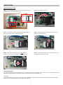
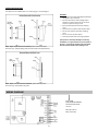
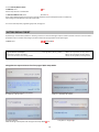
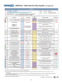
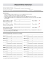
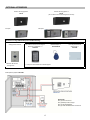
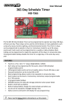
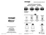
USER MANUAL
USA VERSION
GSM Door / Gate Intercom Entry System For Single Unit GSM‐DE3100
Speaker
Microphone Call Button Optional Accessories: See page 17 DE-H1 Outdoor Housing
DE-H2 Outdoor Housing
with Access Control Keypad
DE-H2 Outdoor Housing
with Camera
Please read this user manual and the quick setup guide completely and keep it for your future reference. MADE IN TAIWAN 4 BAND GSM WIRELESS MODULE MADE IN GERMANY
IP65
Copyright © 2012 by Sentry US. All Rights Reserved. Contents within manual are subject to change without notice. www.sentryus.com R201209‐V17 Disposal of Old Electrical & Electronic Equipment (Applicable in the European Union and other European countries with separate collection systems). This symbol on the product or on its packaging indicates that this product shall not be treated as household waste. Instead it shall be handed over to the applicable collection point for the recycling of electrical and electronic equipment. By ensuring this product is disposed of correctly, you will help prevent potential negative consequences for the environment and human health, which could otherwise be caused by inappropriate waste handling of this product. The recycling of materials will help to conserve natural resources. For more detailed information about recycling of this product, please contact your local city office, your household waste disposal service or the shop where you purchased the product. CAUTION When using this GSM Door / Gate Intercom Entry System, basic safety precautions should always be followed to reduce the risk of fire, electric shock and personal injury. Please read the following before using your equipment. 1. Handle this product with care Avoid any shock or bumping of the product. Improper handling could damage the product. 2. Cleaning Unplug the product before cleaning. Do not use liquid cleaners or aerosol cleaners. Use a damp cloth for cleaning. 3. Requires a proper operating environment This product is designed for outdoor use. Do not use this product near water. Do not use this product near an area where there is a potential of gas leaks or near any fumes that can be explosive. Do not place this equipment near or over a radiator or any other heat source. Avoid using the equipment during an electrical storm. There is a remote risk of electrical shock from lighting. 4. Check the power source voltage The power source voltage should be within the specified range (Product must meet the specifications). Do not overload the wall outlet or power cord where the power adapter is installed. This can result in fire or electric shock. 5. Objects and liquid entry Never push objects of any kind into this product as this may touch dangerous voltage points of short out parts that could result in a fire or electric shock. Never spill any kind of liquid on the product. 2
INDEX CAUTION ................................................................................................................................................................ 2 FRONT PAGE OF QUICK SETUP GUIDE ..................................................................................................................... 4 PACKAGE CONTENTS .............................................................................................................................................. 5 INTRODUCTION ...................................................................................................................................................... 5 ROLE ASSIGNMENT .............................................................................................................................................. 5‐6 INSTALLATION ..................................................................................................................................................... 7‐8 SIM CARD INSTALLATION ........................................................................................................................................ 7 SYSTEM INSTALLATION ............................................................................................................................................ 8 WIRIING DIAGRAM ................................................................................................................................................. 8 WIRING LOCKS ....................................................................................................................................................... 9 LED INDICATORS .................................................................................................................................................. 10 ADDING ADMINS & USERS ............................................................................................................................... 10‐11 ADDING ADMINS ................................................................................................................................................... 10 UPGRADING AN ADMIN TO POWER ADMIN ......................................................................................................... 10 ADDING USERS ................................................................................................................................................. 10‐11 CHANGING PASSCODES & CODES.......................................................................................................................... 11 SOUND MONITORING MODE ................................................................................................................................ 11 REMOTE UNLOCK ................................................................................................................................................. 12 ADJUSTMENTS ..................................................................................................................................................... 12 OTHER PROGRAMMING KEY CODES ................................................................................................................ 12‐13 LIST ALL NUMBERS STORED IN SYSTEM ................................................................................................................ 12 CHECK STATUS .................................................................................................................................................. 12‐13 FACTORY DEFAULT RESET ..................................................................................................................................... 13 BACK PAGE OF QUICK SETUP GUIDE ..................................................................................................................... 14 SPECIFICATIONS ................................................................................................................................................... 15 TROUBLESHOOTING ............................................................................................................................................. 15 WARRANTY .......................................................................................................................................................... 15 PROGRAMMING WORKSHEET .............................................................................................................................. 16 OPTIONAL ACCESSORIES ....................................................................................................................................... 17 3
See page 13 for enlarged
screen capture pictures
4
PACKAGE CONTENTS 1) Panel – Front 5) Panel – Rear with Plastic Back Cover 6) Power Adapter 12V DC 1.5A Two (2) Security Screws & Locking Washer 2) 3)
4)
GSM External Antenna 3M Sticker + One (1) (9.8ft/3m lead) Screw & Wall Anchor with Bracket for Antenna Bracket 8)
9)
Stainless Steel Surface Mount Panel Housing 7)
Allen Wrench for Security Screws User Manual Quick Setup Guide For any returns, please include all components listed above with original packaging in Resalable Condition. Absolutely No Returns will be accepted if any component is missing / damaged. INTRODUCTION The GSM Door / Gate Intercom Entry System is an intercom access system installed at the entrance of a door or gate. It is an ideal product replacing the traditional door phone. It allows up to three (3) Admins (1 Power Admin and 2 Admins) and up to one hundred (100) Users access to entrance with an option to provide remote access for visitors who use the system to call the homeowner or manager. The system has a default talk time of 55 seconds with a maximum talk time of 999 seconcds. There are three options of remote access into the system. Option 1: The visitor can push the call button on the system. Once the Admin receives the call, they can unlock the gate from a remote location by simply pressing a (star) command on their cell phone or ignoring the call. Option 2: The Admin can call into the system and remotely dial a command ( 33 5678# ‐‐ default) to momentarily release the lock. Option 3: Registered users (up to 100) can dial into the system, and if recognized, will allow automatic unlock through Caller ID recognition. This system gives the opportunity not only to know who is waiting at the entrance from a remote location but also to control the access point. Use of this system at your company or house does not require any special installation or wiring. Simply install this system and connect the door latch and power supply. ROLE ASSIGNMENT The system has the ability to store 3 Admin accounts (1 Power Admin + 2 Admins) and 100 User accounts. Registered Admins have the ability to call into the system and enter dial codes or SMS codes to access functions. Separate roles can be assigned to an Admin. Users are allowed to make calls into the system and are allowed entry into door/gate by dialing in. Users are recognized by Caller ID and if Caller ID is not recognized, call is ignored. When a registered User dials into the system they are limited to opening the door/gate only. THE DIFFERENT ROLES OF ADMIN & POWER ADMIN The system is set to call Admin 11 first if the call button is pushed. After 18 seconds (default) and there is no answer, the phone call is disconnected and diverted to dial Admin 12. If no answer, then system diverts to dial Admin 13. Depending on service provider, Ring Divert Time 5
(ITEM 17 on page 14) may be adjusted from 10 seconds to 99 seconds to adjust for different GSM service providers for voicemail answering. To register for one Admin only (11, 12, 13), set Ring Divert Time to 99 seconds. It is important to know that each Admin can dial program the system but only one (1) of the Admins (11, 12, 13) can register admins, users, and change system settings via SMS. This person with SMS capability is referred to as the Power Admin. Note: Once the power is unplugged from the system, the Power Admin is erased from the system. The Passcode should be kept confidential and be released to qualified Admins only. Role Assignment Examples: Example 1: A Single‐family Home Person Admin Functions Settings When the call button is pressed, this is the first person that the system calls. Has the option of adding users. Homeowner Cell phone with no SMS feature Admin 11 Family Member 1 Smart phone Admin 12 *Upgraded to Power Admin When the call button is pressed and Admin 11 does not answer, this is the second person that the system calls. Has the ability to add users and change settings in system via dial in or SMS. Family Member 2 Land line Admin 13 When the call button is pressed and Admin 11 and 12 does not answer, this is the third person the system calls. Users: In‐laws, gardener, babysitter, dog walker * Not Admin *registered as User Any user with a phone number registered into the system can call the system’s SIM card phone number to unlock the door/gate. Homeowner’s phone number is registered to Admin 11; Family Member 1 is registered to Admin 12; Family Member 2 is registered to Admin 13. Admin 12’s phone number is also registered as a Power Admin in order to add users, program & receive confirmations via SMS. Admin 11 and 12 know the Passcode and Admin 13 does not. Ring Divert Time is set to default (18 sec), so the system will call each Admin’s phone number in order, but hang up before the call goes to voice mail. Any person who needs to be able to unlock the door/gate without talking to the Homeowner/Family Member may call the system from a cell phone to unlock it themselves if their number is registered into the system.
Result: Admin 11 is limited to adding users by dialing in. Since Admin 12 owns a smart phone, Admin 12 can register and check users in the system via SMS. Admin 11 and 12 would like Admin 13 to accept visitors when Admin 11 and 12 are unavailable, but does not allow Admin 13 to program the system, so the Passcode is kept confidential from Admin 13. Trusted guests can be registered as Users in the system to unlock the door/gate themselves by calling into the system. Example 2: A Small Office Person Admin Functions Settings Front Desk Receptionist Land line Admin 11 Office Manager Smart phone Admin 12 *Upgraded to Power Admin Has the ability to change system settings and add or delete users via dial in or SMS. Users: Employees and Vendors Not Admin *registered as User Any user with a phone number registered into the system can call the system’s phone number to unlock the door. The exclusive number that receives calls and can allow visitors in. The Front Desk Receptionists’ phone number is registered to Admin 11 and Office Manager’s phone number is registered to Admin 12. Admin 12’s phone number is also registered as a Power Admin in order to add users, program & receive confirmations via SMS. Admin 12 knows the Passcode. Ring Divert time is set to 99 seconds, so the system will call Admin 11’s phone number and continue to ring without calling Admin 12 or 13. All employees’ and vendors’ phone numbers are registered into the system so they are able to unlock the door for themselves by calling the system without requesting access from the receptionist. Result: Whenever a visitor presses the call button, the front desk phone, which is set to Admin 11, will ring and the receptionist can choose to unlock the door for the visitor or not. Adding users and changing system settings will be done by the office manager Admin 12. The employees of the office and vendors needing to make deliveries all have their phone numbers registered into the system and can call into the system to unlock the door themselves. 6
INSTALLATION SIM CARD INSTALLATION STEP 1. Face the panel so the SIM card tray is on the bottom left corner. Slide SIM card tray door left to unlock the tray. STEP 2. Flip up SIM card tray door. STEP 3. Insert SIM card into tray door with notched side of SIM card facing up and metal contacts on SIM card facing left. STEP 5. Slide tray door to the right in order to lock SIM card into place. A “click” sound will indicate the tray door is locked. STEP 4. Gently push down to close tray door and pay careful attention to notch of SIM card. STEP 6. Test system by powering on. A trouble beep will sound if the SIM card is installed incorrectly. GSM SIM Card Reminder: As a reminder, please make sure you understand your Terms of Service with your GSM provider. The door entry system will not work without a valid GSM SIM card. Works well with prepaid cards or subscription based cellular services using GSM only. For example: Some service providers in the USA such as T‐Mobile or AT&T have different service plans. Be aware that some plans may lose subscribed number if prepaid card isn’t renewed after one year even if there still is a balance. 7
SYSTEM INSTALLATION The system can be installed either on a surface (Fig. 2) or recessed (Fig. 4). NOTE: Before surface mounted installation, please remove the plastic back cover (Fig. 1) before fitting panel into the stainless steel panel housing.
ADVISORY: 9 Light gauge is recommended (22ga stranded) for wiring unit’s open command. 9 Seal unit with silicone sealant paying careful attention to metal housing. Do not use silicon sealant on plastic housing or cover. 9 Be very careful with antenna when installing cover. 9 Tape antenna connections with electrical tape. 9 Do not pinch antenna cable when installing cover. 9 Do not use near sprinkler system. 9 Disconnect power when servicing equipment. If the system is constantly emitting a tone during installation, it’s a sign that there is poor reception in the area. To remedy the situation move the cellular antenna until the module stops emitting a tone. NOTE: Before recessed mounted installation, please KEEP the plastic back cover (Fig. 3) attached to the panel. WIRING DIAGRAM 4 Band GSM (900/1800/850/1900MHZ) Wireless Module MC55i Terminal Made by Cinterion Made in Germany 8
WIRING LOCKS Depending on lock installed, the power can be sourced from the existing 12V DC 1.5A power supply or supplied separately using external power supply. Please be advised when sourcing power from door system, it should match required voltage with lock being installed. It is advised to install a separate external power supply for locks. WIRING LOCKS USING “SYSTEM” POWER SUPPLY WIRING LOCKS USING “EXTERNAL” POWER SUPPLY For Battery Backup recommendation, see page 17‐18 or visit www.sentryus.com/module.php. For reference of a Typical Lock Power Consumption, see page 13. 9
LED INDICATORS LED Status Indicator Red Flashing = Standby Red Solid = Using LED Network Indicator Red flashes once per 3 seconds = Ready Red flashes once per second = Searching Red Solid = Busy LED Power Indicator Red Solid = Power On Red Off = Power Off ADDING ADMINS & USERS ADDING ADMINS The system has the ability to store one (1) Power Admin and three (3) Admins, where the Power Admin is an upgraded status for SMS programming and confirmation. Note: An Admin must be added into the system before adding users or changing settings. One of the Admins must be used to be upgraded to a Power Admin. When registering a user for dialing in, the owner has to add the country code “1” before the phone number. The default Passcode is 1234. 1) Use your cell phone to dial into the system by entering the phone number of the SIM Card installed in the system. You will hear a long tone when the door system answers the call. 2) To add first Admin, enter: 12 1234 # 11 1phonenumber # To add a second Admin, enter: 12 1234 # 12 1phonenumber # To add a third Admin, enter: 12 1234 # 13 1phonenumber # Note: Successful key code acceptance is followed by one long tone. Unsuccessful key code is followed by three short tones. There is no option to delete an Admin, but an Admin can be overwritten. Example 1: An Admin wants to register Admin 11 into the system. His phone number is 999‐555‐1234. Step 1 Step 2 Step 3 Step 4 Step 5 Step 6 Enter Program Admin Passcode End Passcode Admin Country Code + Telephone Number End (11 digits ‐‐ including country code 1 & Mode (11, 12, 13) phone number with area code) 12 1234 # 11 1 999 555 1234 # UPGRADING AN ADMIN TO POWER ADMIN To upgrade an Admin to a Power Admin, enter Admin Program Mode ( 12 ) then use function code 74. To upgrade Admin to Power Admin for SMS programmability, enter: 12 1234 # 74 1phonenumber # Note: SMS texts are limited to 140 characters per message To remove Power Admin status when using SMS programming.
for SMS programmability, enter: 12 1234 # 74 1phonenumber # Example 2: An Admin wants to upgrade Admin 11 to Power Admin. Step 1 Step 2 Step 3 Step 4 Step 5 Step 6 Enter Program Admin Passcode End Passcode Function Code Country Code + Telephone Number End (11 digits ‐‐ including country code 1 & Mode phone number with area code) 12 1234 # 74 1 999 555 1234 # ADDING USERS An Admin has the responsibility of adding users into the system. Input 1‐100 user IDs; 3 digit place holders not necessary 12 1234 # 72 1 1phonenumber # To add User 1, enter: To add User 2, enter: 12 1234 # 72 2 1phonenumber # To add User 9, enter: 12 1234 # 72 9 1phonenumber # 10
To add User 20, enter: 12 1234 # 72 20 1phonenumber # To add User 100, enter: 12 1234 # 72 100 1phonenumber # 12 1234 # 73 usernumber 1phonenumber # To delete a User, enter: To delete all Users, enter: 12 1234 # 73 # Example 3: An Admin wants to program User 2 into the system. His phone number is 999‐888‐4321. Step 1 Step 2 Step 3 Step 4 Step 5 Step 6 Enter Program Admin Passcode End Passcode Function Code User Number Country Code + Telephone Number (11 digits ‐‐ including country code 1 & Mode (0‐100) Step 7 End phone number with area code) 12 1234 # 72 2 1 999 888 4321 # CHANGING PASSCODES & CODES To change Passcode from 1234 to your own, enter: 12 1234 # 01 # = new 4 digit passcode To change Relay Hold & Release Code 12 1234 # 02 # from 5678 to your own, enter: = new 4 digit passcode To change Sound Monitoring Code from 1212 to your own, enter: 12 1234 # 03 # = new 4 digit passcode To change Unlock System Code, enter: 12 1234 # 61 x # Changes the door unlock symbol code to open door from default ( ) to another digit/symbol. To change Hold System Unlock Code, enter: 12 1234 # 63 x # Changes the hold door unlock code from default (#) to another digit/symbol. To change Lock System Code, enter: 12 1234 # 64 x # Changes the lock door system code from default (1) to another digit. To change International Country Code, enter: 12 1234 # 71 countrycode # The country code can be 1‐3 digits. The default is set to country code 1 for USA. 12 1234 # 65 x # To change Call into Type, enter: When Admin calls into the system, it goes into the default programming mode (1). An admin can change the system’s call in mode from programming mode to talk time mode (so no programming can be done). The default is set to 1. x = 1 for programming mode or 2 for talk time. SOUND MONITORING MODE Admins have an option to listen to what is happening outside the door/gate while the microphone is disabled. The default Sound Monitoring Code is 1212. You can still control the door/gate lock mechanism when you are under sound monitoring mode. 1) Use your cell phone to dial into the system by entering the phone number of the SIM Card installed in the system. The system will then verify your phone number with the predefined numbers. You will hear a long tone when the door system answers the call. Optionally you can SMS the system with same key code and the system will call back Power Admin. 2) To enter Sound Monitoring Mode – Listen Only, enter: 13 1212 # Speaker is off under the Sound Monitoring Mode. To enable microphone for 2‐way communication, enter command key code 35 #. 11
REMOTE UNLOCK The default Relay Hold & Release Code is 5678. 1) Use your cell phone to dial into the system by entering the phone number of the SIM Card installed in the system. The system will then verify your phone number with the predefined numbers. You will hear a long tone when the door system answers the call. 2) To have Admin Call in to Unlock: 33 # Momentary (Trigger Relay), enter: Admin can call into the system to unlock the door only once. 3) To have Admin Call in to Unlock: Unlimited (Relay Hold), enter: 34 # Admin can call into the system to unlock the door more than once – unlimited. 4) To have Admin Call in to Lock (Relay Release), enter: 35 # Admin can call into the system to lock the door. ADJUSTMENTS To adjust Speaker Volume, enter: 12 1234 # 3 x # Volume level x = 1, 2, 3, 4 where 1 = low and 4 = high. The default is set to level 3. To adjust Mic Volume, enter: 12 1234 # 4 x # Volume level x = 1, 2, 3, 4 where 1 = low and 4 = high. The default is set to level 3. To adjust system Open Time, enter: 12 1234 # 51 x # The open time is how long the door stays unlocked after being activated. The default is 8 seconds. x = time in seconds (1‐9) To adjust Ring Divert Time, enter: 12 1234 # 52 xx # The ring divert time is how long the phone call stays ringing before diverting to the next Admin. The default is 18 seconds. xx = 10‐99 seconds 12 1234 # 53 xxx # To adjust Call/Talk Time, enter: Call/talk time is how long the phone stays connected before hanging up. The default is 55 seconds. xxx = 005‐999 seconds OTHER PROGRAMMING KEY CODES LIST ALL NUMBERS STORED IN SYSTEM The Power Admin is able to receive an SMS text with a list of all the phone numbers stored in the system. To List all Phone Numbers stored in the system, enter: 21 # CHECK STATUS To check the Lock (Relay) Status, enter: 22 # Relay on = unlocked; Relay off = locked Detect = on/off 20 # To check GSM Signal Status, enter: When a request for GSM signal strength message is sent to the system, it will send a SMS reply with one digit signal strength code between 0~4. Signal strength lower than level 3 may cause operational problems such as loss of speech quality (and possibly missing DTMF tones) and network loss. x = 0‐4, 0 being the lowest and 4 being the highest 12
To check Minutes/Balance Status on SIM Card, enter: 23 # Feature may not work in United States. To Add Check Balance Code, enter: 78 xxxxxxx # Enter code for SMS check balance from service provider (related to check minutes/balance status on SIM card). *Must change to Check Balance Code of Service Provider. For a chart of the important programming key codes, see page 14. FACTORY DEFAULT RESET If performing a “reset to factory default” is necessary, make sure to record all settings and phone numbers of admin and users. Once hard reset is performed, all phone numbers and settings are erased and must be reprogrammed into the system again. 12 1234 # 999 # To Reset, enter: FOR REFERENCE ONLY Striek Lock
Typical Lock Power Consumption 12V DC @ 250mA / 24V DC @ 150mA Please refer to all power consumption details in the lock manual for lock being installed. Enlarged Screen Capture Pictures from front page of Quick Setup Guide: ITEM 9: List all Numbers Stored in the System. O = admin / I = user / E= end Mag Lock 300 lbs: 12V DC @ 420mA / 24V DC @ 210mA 600 lbs: 12V DC @ 500mA / 24V DC @ 250mA 1200 lbs: 12V DC @ 500mA / 24V DC @ 250mA ITEM 10: Check Lock (Relay) Status. Relay on = unlocked / off = locked Entry OK confirmed. ITEM 18: Change Unlock System Code. Change from factory default to 0. 13
Entry Failure – Forgot # Sign Copyright © 2012 by Sentry US. 14
SPECIFICATIONS Model Operating Voltage Operating Current GSM Frequency / Module Protection Humidity Operating Temperature Faceplate Dimension (L x W x H) Module Housing Dimension (L x W x H) GSM‐DE3100 12V DC or 24V AC (includes 12V DC 1.5A Power Adapter) Under 12V DC: 55mA Standby, 250mA max GSM 850/900/1800/1900 Wireless Module Made in Germany by Cinterion IP65 Less than 80% RH ‐4°F ~ 122°F / ‐20°C ~ 50°C 6.69” x 3.94” / 170mm x 100mm 6.85” x 4.44” x 2.56” / 174mm x 113mm x 65mm 1.14” x 0.7” / 29 x 17 mm Lead Length: Approx. 9.84ft / 3m *Specifications are subject to change without notice. Antenna Dimension (DIA‐base x H) TROUBLESHOOTING If a constant beep occurs when the system is initialized, the following components will need to be checked: 1) SIM Card: Please check to see if the SIM card is fitted properly into the door of the SIM card holder and locked properly. 2) Antenna: Please make sure the antenna is installed properly and positioned in a location that receives GSM signal. Also make sure the antenna lead is not broken. Sentry US Technical Support Line: 1‐800‐872‐9907 Mon.‐Fri. 9am – 5pm PST LIMITED ONE (1) YEAR WARRANTY AND EXCLUSIONS Manufacturer warrants to the original consumer purchaser and not for the benefit of anyone else that this product at the time of its sale by Manufacturer is free of defects in materials and workmanship under normal and proper use for one (1) year from the purchase date. Manufacturer's only obligation is to correct such defects by repair or replacement, at its option, if within such one (1) year period the product is returned prepaid, with proof of purchase date, and a description of the problem. This warrant excludes and there is disclaimed liability for labor for removal of this product or reinstallation. Warranty is voided if this product is installed improperly or in an improper environment, overloaded, misused, opened, abused, or altered in any manner, or is not used under normal operating conditions or not in accordance with any labels or instructions. There are no other implied warranties of any kind, including merchantability and fitness or a particular purpose, but if any implied warranty is required by the applicable jurisdiction, the duration of any such implied warrant, including merchantability and fitness of or a particular purpose, is limited to one (1) year. Manufacturer is not liable for incidental, indirect, special, or consequential damages, including without limitation, damage to, or loss of use of, any equipment, loss sales or profits or delay or failure to perform this warranty obligation. The remedies, provided therein are the exclusive remedies under this warranty, whether based on contract, tort or otherwise. For damage requiring service, unplug the product from any power source and refer service to qualified servicing personnel under the following conditions: a. When the power supply cord or plug is damaged. b. If liquid has been spilled, or objects have fallen into the product. c. If the product has been exposed to rain or water. d. If the product has been dropped or the housing has been damaged. 15
16
OPTIONAL ACCESSORIES Outdoor Housing Option 2 DE‐H2 (for use with Access Control Keypad or Camera) Outdoor Housing Option 1 DE‐H1 Example: Examples: Accessories for using GSM‐DE3100 system with DE‐H2 housing:
Stand‐Alone Access Control Keypad RFID EM Keyfob ** Analog Pinhole Camera with Built‐in EM Reader ** ACC‐EMTAG‐B ACSK‐EM * Wireless 3G Camera ** Only to be used with Access Control Keypad
coming soon! Battery Backup System MD‐E‐KIT Proximity Clamshell ID Access Card ** ACC‐EMC Kit Includes: One (1) Indoor Enclosure One (1) Battery Power Charger One (1) 12V DC 8A Battery One (1) 16.5V AC 40VA Power Transformer 17
RELATED PRODUCTS Video Intercom System Security Alert System ‐ Relay and Module 16.5V AC 1.5A Battery Power Charger MD‐BPC612 24V AC 7A Battery Power Charger MD‐BPC61224 High Voltage Relay MD‐HVR 4 Channel Recordable Siren & Voice Annunciator Module MD‐SVOICE4 8 Channel Recordable Voice Annunciator Module MD‐VOICE8 365 Days Schedule Timer MD‐T365 www.SentryUS.com Additional Technology Security Inc. dba: Sentry US 5500 Stewart Avenue Fremont, CA 94538 E‐mail: [email protected] Tel: 1‐800‐916‐8783 18