1
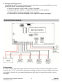
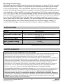
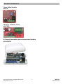
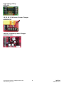
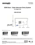
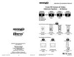
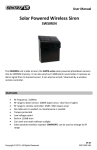
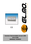
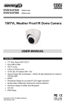
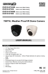
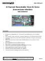
User Manual
4 Channel Recordable Siren & Voice
Annunciator Module
MD-SVOICE4
FEATURES
•
•
•
•
•
•
•
•
•
•
•
4 channels configurable as: 2 siren and 2 recordable voice or 4 recordable
voice.
Siren sounds: classic yelp siren, temporal coded horn, & pulsing industrial horn.
Temporal coded horn meets ANSI standard for audible emergency evacuation
signaling.
Maximum record time is 8 minutes divided between the number of voice
channels.
Recordings stored in non-volatile memory.
Each channel accepts momentary triggers.
"One shot" or continuous repeat voice playback settings.
Built-in condenser microphone for recording.
Adjustable speaker volume and current draw
Powerful 24 watt audio amplifier for speakers
Line level output for paging systems and amplifiers
Please read the Manual before attempting to use this product.
MD-D4
Disposal of Old Electrical & Electronic Equipment (Applicable in the European
Union and other European countries with separate collection systems).
This symbol on the product or on its packaging indicates that this product shall not be treated as
household waste. Instead it shall be handed over to the applicable collection point for the
recycling of electrical and electronic equipment. By ensuring this product is disposed of correctly,
you will help prevent potential negative consequences for the environment and human health,
which could otherwise be caused by inappropriate waste handling of this product. The recycling of
materials will help to conserve natural resources. For more detailed information about recycling of
this product, please contact your local city office, your household waste disposal service or the
shop where you purchased the product.
CAUTION
1. Handle this product with care
Avoid any shock or bumping of the product. Improper handling could damage the
product.
2. Requires a proper operating environment
This product should be mounted within an enclosure.
3. Check the power source voltage
The power source voltage should be within the specified range. (Product must
meet the specifications).
4. Objects and liquid entry
Never push objects of any kind into this product as this may touch dangerous
voltage points of short out parts that could result in a fire or electric shock. Never
spill any kind of liquid on the product.
5. Servicing
Do not attempt to service this product by yourself as opening or removing covers
may expose you to dangerous voltage or other hazards. Refer all service to
qualified servicing personnel.
Copyright © 2012. All Rights Reserved.
www.sentryus.com
2
MD-D4
R201205-V01
6. Damage requiring service
Unplug this product from the power source and refer service to qualified servicing
personnel under the following conditions:
a. When the power supply cord or plug is damaged.
b. If liquid has been spilled, or objects have fallen into the product.
c. If the product has been exposed to rain or water.
d. If the product has been dropped or the cabinet has been damaged.
APPLICATION DIAGRAM
Wiring notes:
A relay or other normally-open switch is used to connect a positive 12V power source
(such as the “+12V” terminal) to a positive voltage activation terminal. When the relay
or switch is closed, the corresponding channel will play its respective sound or voice
message.
Copyright © 2012. All Rights Reserved.
www.sentryus.com
3
MD-D4
R201205-V01
A jumper wire connecting terminal “+S3” and “+B4” will cause either channel to output
an industrial horn sound when activated. A jumper wire connecting a sound channel to
a voice channel will repeat the sound alternating with the voice message when either
channel is activated, until the trigger is disengaged.
OPERATION
The 4 channels of the MD-SVOICE4 must be configured by Jumper JP4, located in the
top left corner of the board. With JP4 in the “Siren” position the unit will be configured
as 2 recordable voice channels and 2 fixed siren sounds. With JP4 in the Voice position,
the unit will be configured as 4 recordable voice channels. Voice messages are stored in
non-volatile memory and may be re-recorded as needed. Simply configure Jumper JP4
according to your choice of operation and connect according to the installation
diagrams and the following instructions.
MODE 1 – SIREN with VOICE Mode: (Jumper JP4 in the SIREN position)
In this mode the 4 channels are split into 2 siren and 2 voice. The siren channels are +S3
(Yelp) and +B4 (Temporal Coded Horn). The voice channels are +V1 and +V2 and have 4
recordable minutes each or 8 minutes combined.
Positive (+) Voltage Activation Terminals
Each channel may be activated by applying 12 Volts DC between the NEG terminal and
the positive (+) input. Both a siren and voice channel may be activated at the same time
to achieve mixed siren and voice output.
+V1 = Recordable Voice Channel 1 input.
+V2 = Recordable Voice Channel 2 input.
+S3 = Yelp Siren input.
+B4 = Temporal Coded Horn input.
Pulsing Voltage Activation
Terminals +S3 and +V1 can automatically detect a pulsed versus a steady activation and
play the alternate channel. For example: if channel +S3 (Yelp) is pulsed then channel
+B4 (Horn) will be played. If channel +V1 (Voice 1) is pulsed then channel +V2 (Voice 2)
will be played.
Mixing Siren and Voice Messages
To combine a siren sound with a voice message apply +12V DC to both a Siren input and
a Voice input at the same time. EG: To obtain a Yelp siren followed by a burglary voice
message, +12V DC voltage to channel +S3 and +V1 at the same time. The two channels
will alternately play until the trigger is removed. Exception: Voice channels can be set to
play only once per activation cycle by placing jumper JP2 to the 1SHOT position. The
siren sound(s) continue until the activation input is removed.
Copyright © 2012. All Rights Reserved.
www.sentryus.com
4
MD-D4
R201205-V01
MODE 2 – VOICE Only Mode: (Jumper JP4 in VOICE position)
In this mode the 4 channels are all voice recordable and can hold up to 2 minutes of
messages each. Two or more channels can be combined into longer messages up to the
combined maximum of 8 minutes.
Positive (+) Voltage Activation
To activate a channel simply apply 12V DC between the NEG terminal and the positive
(+) channel input. Multiple channels can be combined (activated at the same time) to
achieve mixed playback of voice sounds.
+V1 = Recordable Voice Channel 1 input.
+V2 = Recordable Voice Channel 2 input.
+S3 = Recordable Voice Channel 3 input.
+B4 = Recordable Voice Channel 4 input.
NOTE: Pulsing Voltage Activation is not available in Voice Only Mode.
Instructions Common to MODE 1 and MODE 2:
Volume and Current Adjust
Turning the Volume knob clockwise will increase the output volume. The louder the
volume, the higher the current draw. The volume and current draw may be adjusted to
match the current capability of the power source.
Connecting a Constant Power Source
(To Allow Activation By Low Current Devices)
By connecting the +12V and NEG terminals to a constant power source the current
draw of the channel inputs can be reduced to approximately 30mA since all the
operating power will then be drawn from the constant power source. A constant power
source also allows a voice channel to be activated by a momentary voltage and then
finish playing until the end.
Options for Playback of the Voice Channels
The switches marked "Activate Channels" are provided for programming and for user
convenience where manual activation of the channel(s) may be desired. A constant
power source must be connected to +12V and NEG terminals in order to use these
switches.
The 1SHOT position of Jumper JP2 restricts playback of a voice channel to only once per
activation cycle. The channel activation must be removed and then re-applied before
the message will be allowed to play again.
NOTE: 1SHOT does not work with a pulsing activation.
The REPEAT position of Jumper JP2 permits the voice channel to play repeatedly for as
long as the channel input is activated.
Copyright © 2012. All Rights Reserved.
www.sentryus.com
5
MD-D4
R201205-V01
Recording Voice Messages
Messages may be recorded from the on-board microphone, or from a PC with a sound
card and an ELK-129 interface. To record from the onboard microphone place Jumper
JP1 in the MIC position, JP2 in the REPEAT position, and JP3 in the RECORD position.
Activate the desired channel either by using the on-board DIP switches (requires power
to be applied to +12V and NEG terminals) or by applying +12V DC to the desired input
(+V1, +V2, +S3, or +B4). The current message (if any) will start to play. While it is playing,
press and hold the record switch SW1 and speak clearly into the on-board microphone.
Note that the REC/EOM LED should light before you begin speaking. To minimize any
noise, gently release SW1 after speaking. The new message will immediately be played.
To stop the playback turn off the channel switch or remove the trigger voltage. To
re-record the message, or to record another channel, repeat the above procedure.
SPECIFICATIONS
Model
Operating Voltage
Adjustable Current Draw
Low Current Triggers
Max. Sound Level
Max. Speaker Loading
Pulsing Input
MD-SVOICE4
11~14V DC
1/4~1.8 Amp (depending on volume setting and
speaker load)
9~14V DC @ 30mA
122 dB @ 1m
4 ohms
1/2~1.5 sec. pulse, 50% duty cycle
* Specifications are subject to change without notice
LIMITED WARRANTY
LIMITED ONE (1) YEAR WARRANTY AND EXCLUSIONS
Manufacturer warrants to the original consumer purchaser and not for the benefit of anyone else
that this product at the time of its sale by Manufacturer is free of defects in materials and
workmanship under normal and proper use for one (1) year from the purchase date.
Manufacturer's only obligation is to correct such defects by repair or replacement, at its option, if
within such one (1) year period the product is returned prepaid, with proof of purchase date, and
a description of the problem. This warrant excludes and there is disclaimed liability for labor for
removal of this product or reinstallation. This warranty is void if this product is installed
improperly or in an improper environment, overloaded, misused, opened, abused, or altered in
any manner, or is not used under normal operating conditions or not in accordance with any
labels or instructions. There are no other implied warranties of any kind, including
merchantability and fitness or a particular purpose, but if any implied warranty is required by the
applicable jurisdiction, the duration of any such implied warrant, including merchantability and
fitness of or a particular purpose, is limited to one (1) year. Manufacturer is not liable for
incidental, indirect, special, or consequential damages, including without limitation, damage to,
or loss of use of, any equipment, loss sales or profits or delay or failure to perform this warranty
obligation. The remedies, provided therein are the exclusive remedies under this warranty,
whether based on contract, tort or otherwise.
Copyright © 2012. All Rights Reserved.
www.sentryus.com
6
MD-D4
R201205-V01
RELATED PRODUCTS
Timer Relay Module
MD-TR
365 Days Schedule Timer
MD-T365
8 Channel Recordable Voice Annunciator Module
MD-VOICE8
Copyright © 2012. All Rights Reserved.
www.sentryus.com
7
MD-D4
R201205-V01
High Voltage Relay
MD-HVR
16.5V AC 1.5A Battery Power Charger
MD-BPC612
24V AC 7A Battery Power Charger
MD-BPC61224
Copyright © 2012. All Rights Reserved.
www.sentryus.com
8
MD-D4
R201205-V01