1
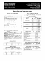
Installation Instructions
TABLE OF CONTENTS
PACKAGE CONTENTS
.........................
SAFETY CONSIDERATIONS
GENERAL
1
....................
2
....................................
LP CONVERSION
Step
PACKAGE
1 - Remove
Step
2 - Modify
Step
3 - Re-install
Step
4 - Check
Burner
Section
Burner/Valve
Burner
Unit
2
KIT INSTALLATION ...........
from
Base
Assembly
Assembly
Operation
3
..........
Unit
.................
Make
3
1 - Remove
Step
2 - Modify
Step
3 - Re-install
Step
4 - Check
Burner
Burner/Valve
Burner
Unit
Adjustments
ALTITUDE
Section
from
Assembly
Assembly
Operation
CRLPELEV004A00
(LP Only)
7
Unit
..........
7
.................
7
....................
and
Make
7
TABLES
8
...........
9
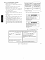
IMPORTANT:
Read these instructions
completely
before
attempting to install this accessory.
IMPORTANT:
The
accessories
described
in
this
installation
instructions
manual are suitable for use on the
models listed below. DO NOT ATTEMPT
TO INSTALL
ON MODELS AND SIZES NOT INCLUDED
IN THESE
TABLES.
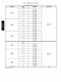
Table
1 - Unit
CARRIER
Check
MODEL
positions
7-8
CRLPELEV009A00
(LP Only)
Usage
MODELS
on unit dataplate
UNIT SIZES
for unit size.
NOMINAL TONS
COMMON
BRYANT MODELS
on unit dataplate
UNIT SIZES
55
5
LH32RF052
51
10
LH32RF067
52
53
54
10
10
10
LH32RF065
LH32RF060
LH32RF055
55
10
LH32RF052
04-16
3-15
581J
04-14
3-12.5
MODELS
dataplate
for unit
size.
NOMINAL TONS
3-12.5
3-15
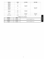
PART NUMBER
NIPPLE, 1/8" PIPE x 1-1/2"
1
CA01 CA006
NIPPLE, 1/8" PIPE x 3-1/2"
1
CA01 CA020
SWITCH, LP PRESSURE
1
HK02LB008
WIRE, BROWN
1
99WG7373XC200918
SPRINGS, LP CONVERSION
LABEL, LP CONVERSION KIT RATING PLATE
2
EF39ZW023
1
48TM502595
LABEL, LP RESPONSIBILITY
1
48TM501014
LABEL, HIGH-ALT. RESPONSIBILITY
1
48TM501015
Package
Contents
Package
for unit size.
NOMINAL TONS
580J
036-180
LH32RF065
LH32RF060
LH32RF055
CA15RA001
CA01 CA001
CRLPELEV003
LABEL, UNIT WARNING
RGS
5
5
5
CA05RA001
3-15
on unit
LH32RF067
52
53
54
1
1
3-10
UNIT SIZES
036-150
LH32RF070
5
1
04-16
4-5-6
5
51
ELBOW, STREET 1/8" NPT x 90°
NIPPLE, 1/8" PIPE x 3/4"
48TC
positions
50
ELBOW, 1/8" NPT x 90 °
3-12.5
MODEL
RGH
LH32RF076
LH32RF073
IIK-CRLPELEV01-05
04-12
Check
5
5
1
04-14
ICP
48
49
QTY
48LC
6-7
LH32RF080
LH32RF079
CONTENTS
48HC
positions
5
5
INSTRUCTIONS
CRLPELEV003, 004A00 ONLY
LABEL, GAS VALVE LP CONV
Check
MODEL
46
47
Necessary
................................
COMPENSATION
CRLPELEV003A00
(LP Only)
6
Base
ORIFICES
QTY
PART NUMBER
SIZE
5
HIGH ALTITUDE CONVERSION KIT
INSTALLATION ...............................
Step
ACCESSORY
PART NO.
Necessary
................................
Adjustments
LP (LIQUID
PROPANE)
AND HIGH
ALTITUDE
KIT
3
....................
and
CONTENTS
(LP)
Contents
CRLPELEV009A00
and
QTY
1
1
CRLPELEV009A00
ONLY
QTY
004A00
Only
PART NUMBER
48TM501013
48TM501012
Only
PART NUMBER
LABEL, GAS VALVE LP CONV
1
48TM504835
LABEL, UNIT WARNING (LP)
SWITCH, TEMPERATURE ACTUATED
1
48TM504836
1
HH18HA147
PACKAGE
CONTENTS
HIGH ALTITUDE
KIT
(NATURAL
ACCESSORY
PART NO.
SIZE
GENERAL
GAS)
ORIFICES
QTY
PART NUMBER
31
5
LH32RF120
32
33
5
5
LH32RF116
LH32RF113
35
36
5
5
LH32RF110
LH32RF105
37
5
LH32RF104
CRLPELEVOO2AO0
38
39
5
5
LH32RF102
LH32RF103
(Natural Gas Only)
44
5
LH32RF086
45
5
LH32RF082
36
10
LH32RF105
37
38
39
10
10
10
LH32RF104
LH32RF102
LH32RF103
CRLPELEVOO1AO0
(Natural Gas Only)
CRLPELEVOO7AO0
(Natural Gas Only)
40
10
LH32RF098
CRLPELEVOO8AO0
41
10
LH32RF096
(Natural Gas Only)
42
43
10
10
LH32RF094
LH32RF089
COMMON CONTENTS
INSTRUCTIONS
LABEL, HIGH-ALT.
RESPONSIBILITY
LABEL, NG CONVERSION
PLATE
SAFETY
QTY
1
KIT RATING
PART NUMBER
IIK-CRLPELEV01-05
1
48TM501015
1
48TM502594
of air-conditioning
equipment
system pressure
and electrical
and qualified service personnel
or
service
air-conditioning
Untrained
personnel
can perform the basic maintenance
functions.
All other operations
should be performed
by
trained
service
personnel.
When
working
on
air-conditioning
equipment,
observe
precautions
in the
literature,
tags and labels attached to the unit, and other
safety precautions
that may apply.
Recognize
all safety
safety
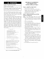
For installations
in Canada,
the input rating must be
derated by 10% for altitudes of 2000 ft (610 m) to 4500 ft
(1372 m) above sea level.
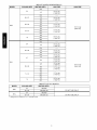
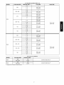
Seven different
gas conversion
kits are available,
as
shown in Package
Contents
table. Each kit contains
a
particular
range of orifice sizes plus other hardware
and
labels necessary
for converting
the unit. Refer to Table
1-4 to determine
the recommended
orifice size based on
the nominal heat size, fuel type, and elevation.
Knowing
this orifice size, it is possible to select the proper Kit
Accessory Part Number from Package Contents table.
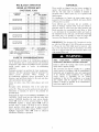
IMPORTANT:
The Accessory
LP Conversion
is not for
use with Low NOx units. If Low NOx units are converted
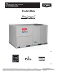
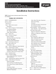
to LP gas, the Low NOx baffle must be removed.
(See
Fig. 1.) The unit will no longer be classified as Low NOx
units. It is suggested that the LP Conversion
Kit be used
with standard units only.
CONSIDERATIONS
Installation
and servicing
can be hazardous
due to
components.
Only trained
should
install,
repair,
equipment.
Follow
gloves.
These models are shipped from the factory equipped to
operate
with natural
gas at elevations
up to 2000 ft
(610 m). The units must be modified
if installed
at
elevations
above 2000 ft (610 m), or if operated
with
liquid propane.
codes.
Wear
information.
safety
This
glasses
is the
and work
safety-alert
symbol A'x. When you see this symbol on the unit and in
instructions
or manuals,
be alert to the potential
for
personal injury.
Understand
the signal words DANGER,
WARNING,
and
CAUTION.
These words are used with the safety-alert
symbol.
DANGER
identifies
the most serious hazards
which will result in severe
personal
injury or death.
WARNING
signifies
a hazard
which
could
result in
personal injury or death. CAUTION
is used to identify
unsafe
practices
which may result in minor personal
injury or product and property damage. NOTE is used to
highlight
suggestions
which
will result
in enhanced
installation,
reliability, or operation.
FIRE,
EXPLOSION,
POISONING,
PROPERTY
CARBON
DAMAGE
MONOXIDE
HAZARD
Failure to follow this warning could result
injury, death or property damage.
in personal
This conversion
kit shall be installed by a qualified
service agency in accordance
with the manufacturer's
instructions
and all applicable
codes and requirements
of the authority
having
jurisdiction.
The qualified
service
agency
is
responsible
for
the
proper
installation
of this kit. The installation
is not proper
and complete
until the operation
of the converted
furnace is checked as specified in the manufacturer's
instructions supplied in the kit.
FEU, EXPLOSION,
EMPOISONNEMENT
CARBON
DE
MONOXYDE,
RISQUE
DOMMAGE _AAPROPRII_TI_
La ndgligeance
de suivre
des blessures personnelles,
la propri6t6.
PAR
DE
l'avis suivant, peut causer
la mort ou du dommage
Cette trousse de conversion doff _tre install6e par un
Entrepreneur
qualifi6,
selon
les
instructions
du
fabricant et doit se conformer _t toutes les exigences et
tout les codes pertinents
de l'autorit6
comp6tente.
[,'Entrepreneur
qualifi6
est
responsable,
et
doff
s'assurer de bien suivre les instructions
dans cet avis.
[,'installation
sera consid_r_
conforme
et rencontrant
les sp6cifications
et instructions
du fabriquant qui sont
inclus dans la trousse, seulement apr6s v6rification de
l'op6ration de la fournaise convertie.
ELECTRICAL
SHOCK HAZARD
Failure to follow
injury or death.
this warning
could
result
in personal
Before installing or servicing system, always turn off
main power to system. There may be more than one
disconnect switch. Tag disconnect switch with suitable
warning label.
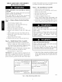
Check that your unit model
number
agrees with Table
LP CONVERSION
INSTALLATION
1.
KIT
NOTE:
Before starting
installation
of this accessory,
check
your unit's
dataplate
for model
and size and
compare to the Unit Usage table on page 1. If your unit's
size designation
exceeds the largest size listed for your
model, STOR This accessory is not for use on your unit.
Consult with your sales office for the correct accessory
part number for use on your unit.
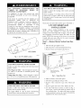
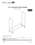
Step 1 m Remove Burner Section
Unit
1. Shut off main
gas supply
from Base
to unit.
2. Shut off power
to unit and install lockout
3. Remove
access panel.
burner
tag.
(See Fig. 2.)
NOx Baffle
000151
Fig. 1 - Low NOx
Baffle
Location
Attach Responsibility
Label Here
(Inside Panel)
_
EXPLOSION,
PERSONAL
Failure to follow
injury or death.
this warning
INJURY
could
HAZARD
result
in personal
WARNING
Label Here
Two-Stage
Gas Valve - Unit is designed to operate at
see Table 6 or NO TAG of manifold
pressure
with
propane gas.
Gas
Burner
Access
Attach Conversion
Rating
(inside
Panel
Kit
Valve
Plate Label Here
Panel)
C09434
Single-Stage
at a 10.0-in.
Gas Valve - Unit is designed to operate
wc of manifold pressure with propane gas.
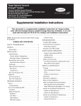
Fig. 2 - Typical
4. Slide out burner
5. Disconnect
FIRE, EXPLOSION,
ELECTRICAL
HAZARD
section
gas piping
Base Unit
side panel.
at unit gas valve.
6. Remove
wire.
wires
connected
to gas valve.
Mark
each
7. Remove
igniter
and sensor wires. Mark each wire.
Failure to follow this warning could result in personal
injury,death or property damage.
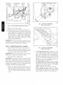
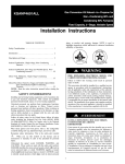
8. For units with burner sections as shown in Fig. 3,
remove the 2 screws that attach the burner rack to
(;as supply MUST be shut off" before disconnecting
electrical power and proceeding with conversion.
the vestibule
plate.
For units with burner sections
as shown in Fig. 5 remove the 4 screws that hold the
manifold to the sheet metal brackets.
Burner Rack
Attach Gas Valve
Gas Valve
Gas
Mounting Screws
(1 of 2 shown)
Converstion
Label here
Manual
Shut-off
Valve
Bracket
to LP
C08238
Fig. 4 - LP Pressure
Switch Piping
(36G Gas Valve Shown)
C08237
Fig. 3 - Gas Section Details (Small Chassis Shown)
9. Remove the gas valve bracket.
10. Slide the burner rack or manifold
out of the unit.
11. For small chassis units only--inspect
the inlet of the
heat exchanger tubes for presence of V-shaped NOx
baffles. (See Fig. 1.) If baffles are present, they must
be removed prior to converting unit for propane gas.
Using needle
nose pliers,
remove
NOx baffles.
Squeeze sides of the baffle, if necessary, to remove
from the heat exchanger tubes.
IMPORTANT:
If this
unit
will
be
converted
back
to
natural gas at a later time, these baffles should be retained
for reuse. Otherwise the baffles may be discarded.
Step 2 m Modify Burner/Valve
1. Separate
burners
Assembly
from frame by removing
2. Remove existing gas orifices.
Install the new orifices from the gas conversion
kit, making sure they
match the recommended
size from Table 1-4.
IMPORTANT:
threads because
3. Remount
Never use Teflon tape to seal gas orifice
peeling tape can plug the orifice.
burners
to support
C10520
Fig. 5 - LP Pressure
screws.
frame.
IMPORTANT:
The burners should be positioned
in the
same order as shipped from the factory. The crossover
flame region of the outermost
burners are pinched off to
prevent excessive
gas flow from the sides of the burner
assembly. If the pinched crossovers
are installed between
two burners, the flame will not ignite properly.
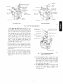
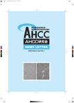
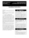
4. Remove the plug on the inlet end of the gas valve
using a 3/16-in. hex wrench. (See Fig. 4 and 6 for
units using White-Rodgers
36G gas valve and Fig.
5 and 7 for units using White-Rodgers
36H gas
valve).
(36H Gas Valve
.
Switch
Piping
Shown)
a. For units with 36G valve, install the l/s-in,
x
11/2-in. nipple where the plug was removed.
(See
Fig. 4.) Use pipe thread dope or tape (field-supplied, must be certified
for use with propane gas)
for all ,joints, making sure not to get any excess in
the pipe or valve. Next, install the l/s-in,
x 90 °
elbow, then l/s-in, x 3/4-in. nipple, followed by the
LP Pressure Switch as shown in Fig. 4.
For Single-Stage
Gas Valves, connect
supplied
brown jumper wire from the "NO" (Normally Open)
terminal
on the pressure
switch to the terminal
where the gray wire was attached.
NOTE: Terminals are not marked on Gas Valve.
For Two-Stage
Gas Valves, connect the supplied
brown jumper wire from the "NO" terminal on the
pressure switch to terminal "M" on the gas valve.
REGULATOR
f
REGULATORCOVERSCREW
OVERSCREW
PLASTIC
ON/OFF
SWITCH
f
ON/OFF
(Propane
Natural
1/2" NPT INLET
DJUST
SCREW
SWITCH
- White,
REGULATOR
SPRING
(PROPANE-WHITE
- Silver)
"_
HIGH STAGE GAS
1/2" NPT INLET
PRESSURE REGULATOR
ADJUSTMENT
TURAL
LOW STAGE
INLET
PRESSURETAP
- SILVER)
REGULATOR
GAS PRESSURE
INLET
REGULATOR
PRESSURETAP
ADJUSTMENT
ADJUSTMENT
GAS PRESSURE
MANIFOLD
MANIFOLD
PRESSURE TAP
ESSURETAP
1/2" NPT OUTLET
1/2"
NPT OUTLET
Two-Stage 36G VaIve
Single-Stage 36G Valve
C10521
Fig. 6 - 36G Valve
Spring
Installation
b. For units with 36H valve, install the l/s-in x
3/4-in nipple where the plug was removed. (See
Fig. 5.) Use pipe thread dope or tape (field supplied,
must be certified for use with propane gas) for all
joints, making sure not to get any excess in the pipe
or valve. Next, install the gas valve bracket over
nipple, then the 1/8-in x 90 ° elbow, then 1/8-in x
31/2-in nipple, then 1/8-in x 90 ° street elbow,
followed by the LP Pressure Switch as shown in
Fig. 5. Connect he supplied brown jumper wire
from the "NO" terminal on the pressure switch to
terminal "MP" on the gas valve.
Single stage arid two stage
,_latcn"cover screw
Regulator aE_:UStscrew
/
Regulato_ sp:ring
J
6. Remove regulator cover screw(s) from gas regulator(s). (See Fig. 6 or 7.) Save regulator cover screws.
7. Using a screwdriver, remove plastic adjust screw(s)
from both regulators. (See Fig. 6 or 7.) Save plastic
adjust screws.
8. Remove regulator spring(s) (silver) from gas regulator(s). (See Fig. 6 or 7.) Discard regulator springs.
9. Install propane gas regulator spring(s) (white)
shipped with the kit into the gas regulator(s). (See
Fig. 6 or 7.)
Outlet pr'essul'etap
C08241
Fig. 7 - Two-Stage
Spring Installation
(36H Gas Valve Shown)
10. For Two-Stage Gas Valves, install plastic adjust
screw into the high stage gas regulator, turn clockwise 13.5 turns. (See Fig. 6 and 7.) Then install
plastic adjust screw into the low stage gas regulator,
turn clockwise
9.5 turns. Replace
regulator
cover screws. (See Fig. 6 and 7.)
11. For Single-Stage Gas Valves, install plastic adjust
screw into the single-stage
gas regulator, turn
clockwise 13.5 turns. Replace regulator cover
screw. (See Fig. 6.)
Step 3 m Re-install
1. Slide the burner
Burner
rack into the unit.
2. Attach
moved
burner rack or manifold
screws.
3. Fasten
gas valve bracket
4. Reconnect
f
Assembly
the igniter
CONVERTED
re-
gas piping
TO L.P
GAS WITH FACTORY
SUPPLIED
SUPPLIED PARTS.
in base.
wires.
PARTS.
MANIFOLD PRESSURE,
10.0"we
MANIFOLD PRESSURE,
6.2"wc
5. Reconnect
the wires to the gas valve, except for the
grey wire. Connect the grey wire to to terminal "C"
on the pressure switch.
6. Connect
CONVERTED
TO L.P
GAS WITH FACTORY
with 2 screws
and sensor
THIS UNiT HAS BEEN
THIS UNiT HAS BEEN
with previously
J
For 48LCF/T*12
to the gas valve.
Only
C13290
7. Attach LP Conversion
3 and 8.)
8. Attach Warning
Fig. 2 and 9.)
Label to gas valve.
Label to burner
access
(See Fig.
panel.
Fig. 8 - Gas Valve Conversion
(See
Label
(LP Only)
WARNING
9. Attach completed
LP Responsibility
Label to inside
of burner access panel. (See Fig. 2 and 10.)
THIS
UNIT
IS DESIGNED
OF MANIFOLD
10. For High Altitude LP installations
attach LP Conversion Kit Rating Plate Label to inside of burner
access panel. (See Fig. 2 and 11.)
EXCEEDING
THIS
EXPLOSION
OR INJURY.
For 48LCF/T*12
11. Leak check all gas connections
including the main
service connection, gas valve, gas spuds, and manifold
pipe plug. All leaks must be repaired before firing
unit.
TO OPERATE
PRESSURE
WITH
PRESSURE
AT 6.2 + 0.3"
L P. GAS.
WILL CAUSE
Only
WARNING
THIS
OF
UNIT
IS DESIGNED
MANIFOLD
TO OPERATE
PRESSURE
EXCEEDING
THIS
EXPLOSION
OR INJURY.
WITH
PRESSURE
AT 10.0 + 0.3"
L P. GAS.
WILL
CAUSE
For all others.
C13289
Fig. 9 - Unit Warning
Label
(LP Only)
f
'THIS FURNACE
WAS CONVERTED
TO PROPANE
DAY
MONTH
ON
GAS
C¢: GC:N¢:RATEUR
CONVERTI
LE
D'AIR CHAUD
=
dOUR
YEAR
=
MOIS
POUR
ANNEE
GAZ DE PETROLE_ LIQU#FIE
USING
ORIFICE
A ¢:T¢:_
OU
SIZE.
PROPANE
BY.
SI L'ORIFICE
INDENTIQUE
AU TROU
EST
D'UN FORET N°
PAR.
(Name and address of organization
making this conversion),
which accepts the responsibiRy
that this conversion has
been properly
made.
48TM501014 REV-
(Nom et adresse
qui accepte
de I' organisme
I' entnere
qui a effectue
responsablilit6
la conversion),
de la conversion.
.2
.J
C08242
Fig. 10 - LP Responsibility
Label
FIRE
AND EXPLOSION
FOR 48LCF/T*12 PROPANE
CONVERSION
ONLY
All other models go to Step 5.
HAZARD
Failure to follow this warning could result in personal
injury and/or property damage.
Never test for gas leaks with an open flame. Use a
commercially available soap solution made specifically
for the detection of leaks to check all connections.
The newly installed
low gas pressure switch is a safety
device used to guard against adverse
burner operating
characteristics
that can result
from low gas supply
pressure.
Switch opens at not less than 7.2-in. wc and
closes at not greater than 10.2-in. wc.
This switch also prevents operation when the propane tank
level is low which
can result
in gas with a high
concentration
of impurities,
additives,
and residues that
have settled to the bottom of the tank. Operation
under
these conditions
can cause harm to the heat exchanger
system. This normally
open switch closes when gas is
supplied to gas valve under normal LP operation pressure
of 11.0 to 13.0-in.wc.
The closed switch completes
the
control circuit. Should an interruption
or reduction in gas
supply occur, the gas pressure at switch drops below low
gas pressure
switch
setting,
and switch
opens.
Any
interruption
in control circuit (in which low gas pressure
switch is wired) quickly closes gas valve and stops gas
flow to burners.
CONVERSION KIT RATING
PROPANE GAS
PLATE
REFER TO MAIN DATING PLATE EOR SPECIFIC MOREL NUMBER
THIS UNIT DAD OEEN CONVENTEO TO OPERATE WIT_ PROPANE GAS
AT ALTITUOESE_O_ O TO 14.000 EEET
REEER TO NIT IMDTRMDTIOMSPOR ¢OMMEDS!OMPROCEDURES¸
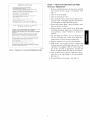
Step 4 _
Install New Limit Switch
1. Remove blower access panel.
2. Locate and remove limit switch
on blower
deck.
3. Replace
with
new limit switch
supplied
CRLPELEV009A00
Propane Conversion
Kit.
4. Reconnect wires to new limit switch.
5. Reinstall
Step 5 _
access
panel.
Check Unit Operation
Necessary
NOTE:
ll-in.we
blower
with
and Make
Adjustments
LP gas supply pressure
or greater than 13-in.we
must not be less than
at the unit connection.
1. Remove manifold
pressure tap plug from manifold
and connect pressure gauge or manometer.
(See Fig.
3.)
2. Turn on electrical
supply.
3. Turn on unit main gas valve.
4. Set room thermostat
to call for heat. If unit has twostage gas valve, verify high-stage
fore attempting to adjust manifold
5. When main burners ignite,
fold, and orifices for leaks.
check
heat operation
pressure.
all fittings,
be-
mani-
6. Adjust high-stage
pressure according
to Table 6 or
NO TAG by turning the plastic adjust screw clockwise to increase pressure, counter-clockwise
to decrease to pressure.
7. For Two-Stage
Gas Valves, set room thermostat
to
call for low-stage
heat. Adjust low-stage
pressure
according to Table 6 or NO TAG.
O0_VENSION KIT PART NUMBERS:DMtPE_EMUOIAOO,CRt?ELEVOOEAOD.CRLPEIENOD3AO0
DNtPELEMOONAOO,CNLDELEMOO_AOO,C_LPEEEMOOSAOO,DRLDEEEVOOgAO0
_ADIFOED PDESSDRE: SEE_NSTALLAT_ON}NSTRUCT}ONS
GAS SUPPLY PREDDNNE: SEE_NSTALLAT}ON}NSTRUQT}ONS
8. Replace
REFER TO ALl!DUDE COMPEMSArIONTAOLED _O_ND IN NIP IMSPM_CI1ONSFOR
REQNI_ED IDFONMATIO_TO DOMDLETE THIS SEOTIO_
IMS[ALEAPIONAE[IPUDE
ORIFICE SIZE IMSTAtLED
INPUT RATE AT INSTAtLATIONALTITUDE
regulator
cover
DTU/MR
FOR INSTALLATIOMSIN CANADA, THE INPUT _ATI_G S_tONLOOE DERATEO OY I0_
FOR ALTITUDESFRO_ E,O00 PT {610_) TO 4,5O0 FP (13_E _) ADOME SEA LEVEL
PLAQUE S!GNALETIQUE
DE TROUSSE DE CONVERSION
GAZ PROPANE
DET AP_AREIL A _AIT L QOJEP O _J_EDO_VEDSIOMPOM_ U_ FOND[IO_NE_E_[AD GAZ PROPANE
A DES ALTITUDESSITD_EO ENTRE 0 ET 14.000 PIEDS
SE REP_RER ANN INSTDMDTIONOFOUDNIE_ AVER LA PRODSSE POUR OBTENI]_LEO PNOD_D@ES
DE CONVERSION¸
10. Turn off unit, remove
place the 1/8-in. pipe
(See Fig. 3.)
NNM_ROUDE P!_DE DES [NONSUE_ DE CONVENTION:DRLDELEVDOIAOO,DNLPELEM@2AO0,
DNLPELEVOO3AOO,CRLDELEVOO_AOO,O_LPELEVOO_AOO,DRL_ELEVOOSAOO,CRLPELEVOOgAo0
11. Re-install
SE R{P_RER
A LA
PLAQUE
SIGNAL_TIQU{
PRIMDIPALE
POUR
LE NMMERO
DE
MODCLE
SDEDIFIQME
burner
PRESSlQNDE COLLEDTENR: VOIRLESINSTRUCTIONSD'INSTALLATION
PRESSIONRE L ADRIV_EOE GAZ : VOIRLESlNSTRUCTIONSD'INSTALLATION
SE R_P_REN AN TAOL_ANDE DOMP_NSATIQNO'ALTITNDEFOMRN_ AVED LA TDONSSE _OUR
LED INFOR_ATIOMSNECESSAINES A E'ADM_ME_ENTDE ¢EPTE SECTION¸
ALTITUDE D'_NSTALtATIOM
,_
PAILLE DE LA DUDE INSIALL_E...........................................................................................................
DADADIT_ D'ENTN_E _ L'ALTITMDED*INSTALEATIOM
DTM/NR
POOR LED IMDTA_tAPIONSANN CANADA. LA DAPADIT_EO ENTREE DOIT _P_E D_DR_DI_E
DE _0;IPOND LEO ALrIT@ED UITUEEO ENTRE _,000 PIED$ (6_0 _IDES) EP 4,5O0 PIEDS
(13_2 M_TNES_ AD DESDUS OU _VEAU OE LA MEN
C13123
Fig. 11 - LP Conversion
Kit Rating Plate Label
screw(s)
when finished.
9. With burner
access panel removed,
observe
unit
heating operation in both high stage and low stage
operation if so equipped.
Observe burner flames to
see if they are blue in appearance,
and that the
flames are approximately
the same for each burner.
_r
access
pressure manometer
and refitting on the gas manifold.
panel.
(See Fig. 2.)
HIGH
ALTITUDE
CONVERSION
KIT INSTALLATION
assembly. If the pinched crossovers
are installed
two burners, the flame will not ignite properly.
Step 3 _
Re-install
1. Slide the burner
FIRE, EXPLOSION
HAZARD
AND ELECTRICAL
SHOCK
2. Attach
burner
3. Replace
between
Burner Assembly
rack into the unit.
rack to vestibule
plate with 2 screws.
gas valve bracket.
Failure to follow this warning could result in personal
injury, death and/or property damage.
4. Reconnect
the igniter
5. Reconnect
wires to gas valve.
Gas supply MUST be shut off before disconnecting
electrical power and proceeding with conversion.
6. Connect
gas piping
and sensor wires.
to the gas valve.
7. Attach completed High Altitude Responsibility
Label
to inside of service access panel. (See Fig. 2 and 12.)
Step 1 m Remove
Burner
Section
from
Base
8. Attach NG Conversion
inside of burner access
Unit
1. Shut off main gas supply to unit.
2. Shut off power to unit and install
3. Remove burner access panel.
lockout
4. Slide out burner section side panel.
5. Disconnect
gas piping at unit gas valve.
6. Remove wires connected
to gas valve.
wire.
7. Remove
8. Remove
igniter and sensor wires.
the 2 screws that attach
the vestibule
9. Remove
tag.
ELECTRICAL
Mark
could result
in personal
Before installing or servicing system, always turn off
main power to system.
There may be more than one
disconnect
switch.
Tag disconnect
switch
with
suitable warning label.
Mark each wire.
the burner rack to
rack out of the unit. (See Fig. 3.)
burners
Assembly
from frame by removing
FIRE
screws.
to support
HAZARD
could
result
in personal
Never test for gas leaks with an open flame. Use a
commercially
available soap solution made specifically
for the detection of leaks to check all connections.
Never use Teflon tape to seal gas orifice
peeling tape can plug the orifice.
burners
AND EXPLOSION
Failure to follow this warning
injury and/or property damage.
2. Remove existing gas orifices.
Install the new orifices from the gas conversion
kit, making sure they
match the recommended
size from Table 1-4.
3. Remount
this warning
the gas valve bracket.
Step 2 m Modify Burner/Valve
IMPORTANT:
threads because
SHOCK HAZARD
Failure to follow
injury or death.
each
plate.
10. Slide the burner
1. Separate
Kit Rating Plate Label to
panel. (See Fig. 2 and 13.)
frame.
9. Leak check all gas connections
including the main
service connection,
gas valve, gas spuds, and manifold pipe plug. All leaks must be repaired before firing unit.
IMPORTANT:
The burners should be positioned
in the
same order as shipped from the factory. The crossover
flame region of the outermost
burners are pinched off to
prevent excessive
gas flow from the sides of the burner
f
f
THIS FURNACE WAS CONVERTED ON
FOR OPERATION AT
DAY
ft
MONTH
CI_ GIeN#RATEUR D'AIR CHAUD A I_TE'
CONVERT[ LE
(_
POUR
JOUR
YEAR
_)mALTITUDE
MOIS
ANNEE
UTILISATION ik UNE ALTITUDE DE
WITH KIT NO.
__
BY,
DE LA TRO_USSE N°.
pi (
)m AU MOYEN
PAR.
(Name and address of organization making this conversion),
which accepts the responsibility that this conversion has
been properly made,
48TM501015
REV-
(Nom
et adresse
de I' organisme
qu! accept e !i entnere
responsab!i!ite
qui a effectue
[a conversion),
d e la conversion.
J
,J
C08243
Fig. 12 - High-Altitude
Responsibility
Label
CONVERSIONKIT RATING PLATE
NATURAL GAS HIGH ALTITUDE
REFER TO MAIN
RATING
PLATE FOR SPECIFIC
THIS
UNIT
HAS BEEN CONVERTED TO OPERATE
MODEL NUMBER
WITH NATURAL
AT ALTITUDES
FROM 2,000
TO 14,000
FEET
UNITS
INSTALLED
AT ALTITUDES
BELOW 2,000
REFER TO NIT INSTRUCTIONS
FOR CONVERSION
Step 4 m Check
Necessary
GAS
PRESSURE:
SUPPLY
REFER TO
RZOUIRER
INPUT
TO
REFER
MAIN
FEET DO NOT REQUIRE
PROCEDURES
RATING
TO MAIN
and
RATE
AT
ALTITUDES
ALTITUDE
IN CANADA,
FROM
2,OR0
FT
TRE
(RiO
RATING
M)
4,50O
TO
SROULD
FT
BE
(ISTR
BERATED
M)
ABOVE
BY
SEA
REF_RER
A
LA
PLAQUE
SIGNAL_TIQUE
PRINCIPALE
POUR
CET APPAREIL
A FAIT
L OBJET
DUNE
CONVERSION
AU GAZ NATUREL
A DES ALTITUDES
SITUEES
ENTRE
LES APPAREILS
INSTALLER
EN
SE REF_RER
AUX
INSTRUCTIONS
LEVEL
5. When main burners ignite,
fold, and orifices for leaks.
LE
NUMERO
DE
NODULE
BESSOUS
DE 2,OO0
PIERS
RE NECESSITENT
FOURNIES
AVEC LA TROUSSE
POUR
OUTENIR
PAR DE CONVERSION
LES PROCEDURES
PRESSION
DE L
ARRIVEE
RE REFERER
DE GAZ
:
SE
A LA
PLAQUE
R_FERER
A LA
SIGNAL_TIQUE
PLAQUE
SE REFERER
AU TABLEAU
DE COMPENSATION
D'ALTITUBE
EOURNI
AVEC
LES INRORMATIONS
RECESSAIRES
A L'ACNEVEMENT
BE CETTE
SECTION.
ALTITUDE
TAILLE
CAPACITE
D'INSTALLATION
DE
LA
RUSE
D'ENTRE£
7. For Two-Stage
PRINCIPALE
SIGNALETIOUE
LA
PRINCIPALE
TRORSSE
all fittings,
be-
mani-
set room
thermostat
to
heat. Verify, then adjust low-
POUR
stage pressure
to value
shown
on rating plate.
M
L'ALTITUDE
8. Replace
B'INSTALLATION
POUR
LES INSTALLATIONS
AUX CAN_BA,
DE ION POUR LES
ALTITUDES
SITUEES
(13TD
M_TRES}
AU DESSUS
DU NIVEAU
LA CAPACITEE
D ENTREE
ENTRE
LORD
PIERS
<610
DE LR BER,
Gas Conversion
regulator
cover
screw(s)
when finished.
BTUINR
DOIT
ETRE DEPRECI_E
METRES)
ET 4,5OO PIERS
Cl1145
Fig. 13 - Natural
Gas '_dlves,
call for low-stage
INSTALLEE
A
check
heat operation
pressure.
pressure.
RUMERQS DE PIECE
DES TROUSSES DE CONVERSION:
CRLPZLZVOO_AOO,CRLPZLZVNODAOO,
CRLPELZVOO3AOO,CRLPELZVOORAOO,CRLPELZVOOTAOO,CRLPELZVOORAOO,CRLPELZVOO9AOO
DE COLLECTEUR:
(See
6. Adjust pressure to value shown on the rating plate
by turning the plastic adjust screw clockwise
to increase pressure,
counter-clockwise
to decrease
to
SP_CIFIQUE
POUR
UN FONCTIONNENENT
2,OOO
ET 14,DO0
PIERS.
DE CONVERSION,
PRESSION
or manometer.
stage gas valve, verify high-stage
fore attempting to adjust manifold
_0%
PLAQUE SIGNALETIQUE DE TROUSSEDE CONVERSION
GAZ NATUREL HAUTE ALTITUDE
SE
gauge
3. Turn on unit main gas valve.
4. Set room thermostat
to call for heat. If unit has two-
RTUIRR
INPUT
pressure
FOR
FT
INSTALLATION
INSTALLATIONS
FOR
connect
2. Turn on electrical supply.
INSTRUCTIONS
INSTALLED
FOR
Adjustments
Fig. 3.)
PLATE
FOUND
IN KIT
SECTION
ALTITUDE
81ZE
and Make
1. Remove manifold pressure tap plug from manifold
CONVERSION
PLATE
RATING
ALTITUDE
COMPENSATION
TABLES
INFORMAT]ON
TO COMPLETE
THIS
INSTALLATION
OR]EICE
REFER
PRESSURE:
Operation
GAS
CONVERSION
NIT PART NUMBERS:
CRLPELEVOOIAOO,CRLPELEVOORAOR,CRLPELEVOORAOR
CRLPELEVOO4AOO,CRLPELEVOOTAOO,CRLPELEVOOBAOO,CRLPELEVOO9AOO
MANIFOLD
Unit
Kit Rating
Plate Label
9. With burner
access panel removed,
observe
unit
heating operation in both high stage and low stage
operation if so equipped.
Observe burner flames to
see if they are blue in appearance,
and that the
flames are approximately
the same for each burner.
10. Turn off unit, remove
place the l/s-in,
pipe
pressure manometer
and refitting on the gas manifold.
(See Fig. 3.)
11. Re-install burner access panel.
(See Fig. 2.)
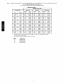
Table
2 - *Altitude
Compensation
for Low NOx Models
48TC04-06
Low NOx Models
Low NOx Models
(L, M, N), 48HC04-06
580J04-06
RGS036,
(L, M, N), and 48LC04-06
and 581J04-06
048, 060 and RGH036,
048, 060
NATURAL GAS ONLY
NOMINAL HEAT INPUT
ELEVATION
Feet
0 -
2000
60k
Meters
0 -
610
BTUH
90k BTUH
120k
BTUH
Orifice
Size
Input
(btu/hr)
Orifice
Size
Input
(btu/hr)
Orifice
Size
Input
(btu/hr)
382
60,000
382
90,000
321
120,000
2000
610
392
55,200
392
82,800
331
110,400
3000
914
740
52,800
740
79,200
331
105,600
4000
1219
_41
50,400
_41
75,600
351
100,800
5000
1524
_41
48,000
_41
72,000
351
96,000
6000
1829
_42
45,600
_42
68,400
361
91,200
7000
2134
742
43,200
742
64,800
361
86,400
8000
2438
_43
40,800
_43
61,200
372
81,600
9000
2743
_43
38,400
_43
57,600
382
76,800
10000
3048
442
36,000
442
54,000
_40
72,000
11000
3353
442
33,600
442
50,400
_41
67,200
12000
3658
452
31,200
452
46,800
_42
62,400
13000
3962
473
28,800
473
43,200
_43
57,600
14000
4267
483
26,400
483
39,600
_43
52,800
* As the height above sea level increases, there is less oxygen per cubic ft. of air. Therefore,
should be reduced at higher altitudes.
1- Not included in kit. May be purchased separately through dealer.
ORIFICE
XX 1
XX 2
XX 3
XX 4
ACC. KIT PN
CRLPELEV001A00
CRLPELEV002A00
CRLPELEV003A00
CRLPELEV004A00
10
heat input rate
(L,M,N)
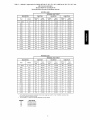
Table3
- *Altitude
Compensation
forModels
48TC04-07
48LC04-06
Models
Models
580J04-07
RGS036,048,060
(D, E,F,S,
R, T),48HC04-06
(D, E,F,S,
(D,E,F,S,R,T)
and 581J04-06
and RGH036,048,060
NATURAL GAS
NOMINAL HEATINPUT
ELEVATION
Feet
0 -
2000
72k BTUH
Meters
0 -
610
115k BTUH
150k BTUH
Orifice
Size
Input
(btu/hr)
Orifice
Size
Input
(btu/hr)
Orifice
Size
Input
(btu/hr)
331
72,000
331
115,000
1-30
150,000
2000
610
351
66,240
351
105,800
1-30
138,000
3000
914
351
63,360
351
101,200
311
132,000
4000
1219
361
60,480
361
96,600
311
126,000
5000
1524
361
57,600
361
92,000
311
120,000
6000
1829
372
54,720
372
87,400
311
114,000
7000
2134
382
51,840
382
82,800
321
108,000
8000
2438
392
48,960
392
78,200
331
102,000
9000
2743
1-40
46,080
1-40
73,600
331
96,000
10000
3048
1-41
43,200
1-41
69,000
351
90,000
11000
3353
1-42
40,320
1-42
64,400
361
84,000
12000
3658
1-43
37,440
1-43
59,800
372
78,000
13000
3962
1-43
34,560
1-43
55,200
382
72,000
14000
4267
442
31,680
442
50,600
1-40
66,000
PROPANE GAS
NOMINAL
ELEVATION
Feet
0 -
2000
72k BTUH
Meters
0 -
610
115k
HEAT
INPUT
BTUH
150k
BTUH
Orifice
Size
Input
(btu/hr)
Orifice
Size
Input
(btu/hr)
Orifice
Size
Input
(btu/hr)
514
72,000
503
115,000
463
150,000
2000
610
514
66,240
514
105,800
473
138,000
3000
914
524
63,360
514
101,200
473
132,000
4000
1219
524
60,480
514
96,600
483
126,000
5000
1524
524
57,600
514
92,000
483
120,000
6000
1829
524
54,720
524
87,400
483
114,000
7000
2134
534
51,840
524
82,800
493
108,000
8000
2438
534
48,960
524
78,200
493
102,000
9000
2743
534
46,080
534
73,600
503
96,000
10000
3048
544
43,200
534
69,000
503
90,000
11000
3353
544
40,320
534
64,400
514
84,000
12000
3658
544
37,440
544
59,800
514
78,000
13000
3962
554
34,560
544
55,200
524
72,000
14000
4267
1-56
31,680
554
50,600
534
66,000
* As the height above sea level increases, there is less oxygen per cubic ft. of air. Therefore,
should be reduced at higher altitudes.
1- Not included in kit. May be purchased separately through dealer.
ORIFICE
XX 1
XX 2
XX 3
XX 4
ACC. KIT PN
CRLPELEV001A00
CRLPELEV002A00
CRLPELEV003A00
CRLPELEV004A00
11
heat input rate
R, T) and
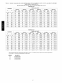
Table
4 - *Altitude
Compensation
for Models
48TC08-14
Models
Models
RGS090,
(D, E, F, S, R, T), 48HC07-12
580J08-14
091, 101, 102, 120, 121, 150 and RGH072,
NATURAL
72k BTUH
FT
M
2000
(D,E,F,S,R,T)
090, 102, 120
GAS
NOMINAL HEAT INPUT
ELEVATION
0 -
(D, E, F, S, R, T) and 48LC07
and 581J07-12
0 -
610
125k
BTUH
150k
BTUH
180k
BTUH
224k
BTUH
250k
BTUH
Orifice
Size
Input
(btu/hr)
Orifice
Size
Input
(btu/hr)
Orifice
Size
Input
(btu/hr)
Orifice
Size
Input
(btu/hr)
Orifice
Size
Input
(btu/hr)
Orifice
Size
Input
(btu/hr)
331
72,000
311
125,000
321
150,000
311
180,000
311
224,000
t30
250,000
2000
610
351
66,240
321
115,000
331
138,000
321
165,600
321
206,080
t30
230,000
3000
914
351
63,360
321
110,000
351
132,000
321
158,400
321
197,120
311
220,000
4000
1219
361
60,480
331
105,000
351
126,000
331
151,200
331
188,160
311
210,000
5000
1524
361
57,600
331
100,000
351
120,000
331
144,000
331
179,200
311
200,000
6000
1829
372
54,720
351
95,000
361
114,000
331
136,800
331
170,240
311
190,000
7000
2134
382
51,840
351
90,000
361
108,000
351
129,600
351
161,280
321
180,000
8000
2438
382
48,960
361
85,000
361
102,000
361
122,400
361
152,320
331
170,000
9000
2743
t40
46,080
372
80,000
372
96,000
372
115,200
372
143,360
331
160,000
10000
3048
t41
43,200
382
75,000
382
90,000
382
108,000
382
134,400
351
150,000
11000
3353
t42
40,320
392
70,000
t40
84,000
392
100,800
392
125,440
361
140,000
12000
3658
t42
37,440
t41
65,000
t40
78,000
t41
93,600
t41
116,480
372
130,000
13000
3962
t43
34,560
t42
60,000
t41
72,000
t42
86,400
t42
107,520
382
120,000
14000
4267
t43
31,680
t43
55,000
t41
66,000
t43
79,200
t43
98,560
t40
110,000
PROPANE GAS
NOMINALHEATINPUT
ELEVATION
72k BTUH
FT
0 -
M
2000
0 -
610
125k
BTUH
150k
BTUH
180k
BTUH
224k
BTUH
250k
BTUH
Orifice
Input
Orifice
Input
Orifice
Input
Orifice
Input
Orifice
Input
Orifice
Input
Size
(btu/hr)
Size
(btu/hr)
Size
(btu/hr)
Size
(btu/hr)
Size
(btu/hr)
Size
(btu/hr)
514
72,000
493
125,000
503
150,000
483
180,000
483
224,000
463
250,000
2000
610
514
66,240
503
115,000
514
138,000
493
165,600
493
206,080
473
230,000
3000
914
524
63,360
503
110,000
514
132,000
493
158,400
493
197,120
473
220,000
4000
1219
524
60,480
503
105,000
514
126,000
493
151,200
493
188,160
483
210,000
5000
1524
524
57,600
514
100,000
514
120,000
503
144,000
503
179,200
483
200,000
6000
1829
524
54,720
514
95,000
524
114,000
503
136,800
503
170,240
483
190,000
7000
2134
534
51,840
514
90,000
524
108,000
503
129,600
503
161,280
493
180,000
8000
2438
534
48,960
524
85,000
524
102,000
514
122,400
514
152,320
493
170,000
9000
2743
534
46,080
524
80,000
534
96,000
514
115,200
514
143,360
503
160,000
10000
3048
544
43,200
524
75,000
534
90,000
524
108,000
524
134,400
503
150,000
11000
3353
544
40,320
534
70,000
534
84,000
524
100,800
524
125,440
514
140,000
12000
3658
544
37,440
534
65,000
534
78,000
534
93,600
534
116,480
514
130,000
13000
3962
554
34,560
544
60,000
534
72,000
534
86,400
534
107,520
524
120,000
14000
4267
554
31,680
544
55,000
554
66,000
544
79,200
544
98,560
534
110,000
* As the height above sea level increases, there is less oxygen per cubic ft. of air. Therefore, heat input rate should be reduced at higher altitudes.
1- Not included in kit. May be purchased separately through dealer.
ORIFICE
ACC.
KIT
PN
XX 1
CRLPELEV001A00
XX 2
CRLPELEV002A00
XX 3
CRLPELEV003A00
XX 4
CRLPELEV004A00
12
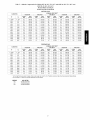
Table
5 - *Altitude
Compensation
for Models
48TC16
48LC08-12
(D, E, F, S, R, T) and 48HC14
(D, E, F, S, R, T) and
(D, E, F, S, R, T)
Models 580J16
Models RGS180
and 581J14
and RGH150
NATURAL GAS
NOMINAL HEAT INPUT
ELEVATION
FT
0-2000
150k BTUH
180k BTUH
240k BTUH
315k BTUH
350k BTUH
M
Orifice
Size
Input
(btu/hr)
Orifice
Size
Input
(btu/hr)
Orifice
Size
Input
(btu/hr)
Orifice
Size
Input
(btu/hr)
Orifice
Size
Input
(btu/hr)
0- 610
377
150,000
377
180,000
377
240,000
t35
315,000
t35
350,000
2000
610
387
138,000
387
165,600
387
220,800
367
289,800
367
322,000
3000
914
397
132,000
397
158,400
397
211,200
367
277,200
367
308,000
4000
1219
397
126,000
397
151,200
397
201,600
377
264,600
377
294,000
5000
1524
408
120,000
408
144,000
408
192,000
377
252,000
377
280,000
6000
1829
418
114,000
418
136,800
418
182,400
387
239,400
387
266,000
7000
2134
428
108,000
428
129,600
428
172,800
397
226,800
397
252,000
8000
2438
428
102,000
428
122,400
428
163,200
408
214,200
408
238,000
9000
2743
438
96,000
438
115,200
438
153,600
418
201,600
418
224,000
10000
3048
438
90,000
438
108,000
438
144,000
428
189,000
428
210,000
11000
3353
t44
84,000
t44
100,800
t44
134,400
438
176,400
438
196,000
12000
3658
t45
78,000
t45
93,600
t45
124,800
438
163,800
438
182,000
13000
3962
t46
72,000
t46
86,400
t46
115,200
t44
151,200
t44
168,000
14000
4267
t47
66,000
t47
79,200
t47
105,600
t45
138,600
t45
154,000
PROPANE GAS
NOMINAL
ELEVATION
150k
FT
M
BTUH
180k
BTUH
240k
HEAT
INPUT
BTUH
252k
BTUH
350k
BTUH
Orifice
Input
Orifice
Input
Orifice
Input
Orifice
Input
Orifice
Input
Size
(btu/hr)
Size
(btu/hr)
Size
(btu/hr)
Size
(btu/hr)
Size
(btu/hr)
0-2000
0-610
529
150,000
529
180,000
529
240,000
519
252,000
519
350,000
2000
610
529
138,000
529
165,600
529
220,800
519
231,840
519
322,000
3000
914
539
132,000
539
158,400
539
211,200
529
221,760
529
308,000
4000
1219
539
126,000
539
151,200
539
201,600
529
211,680
529
294,000
5000
1524
539
120,000
539
144,000
539
192,000
529
201,600
529
280,000
6000
1829
539
114,000
539
136,800
539
182,400
529
191,520
529
266,000
7000
2134
539
108,000
539
129,600
539
172,800
539
181,440
539
252,000
8000
2438
549
102,000
549
122,400
549
163,200
539
171,360
539
238,000
9000
2743
549
96,000
549
115,200
549
153,600
539
161,280
539
224,000
10000
3048
549
90,000
549
108,000
549
144,000
549
151,200
549
210,000
11000
3353
559
84,000
559
100,800
559
134,400
549
141,120
549
196,000
12000
3658
559
78,000
559
93,600
559
124,800
549
131,040
549
182,000
13000
3962
559
72,000
559
86,400
559
115,200
559
120,960
559
168,000
14000
4267
t56
66,000
t56
79,200
t56
105,600
559
110,880
559
154,000
* As the height above sea level increases, there is less oxygen per cubic ft. of air. Therefore, heat input rate should be reduced at higher altitudes.
1- Not included in kit. May be purchased separately through dealer.
ORIFICE
XX 7
XX 8
XX 9
ACC. KIT PN
CRLPELEV007A00
CRLPELEV008A00
CRLPELEV009A00
13
Table
6 - Manifold
CARRIER
MODELS
SIZES
Pressure
Manifold
Settings,
LP
Pressure, LP
LOW FIRE
HIGH
FIRE
04-06
5.0 in. wg
[1245 Pa]
07
48HCD
48HCS
08-09
5.0 in. wg
[1245 Pa]
11-12
5.7 in. wg
[1419 Pa]
14
6.6 in. wg
[1644 Pa]
04-06
5.0 in. wg
[1245 Pa]
5.0 in. wg
[1245 Pa]
07
48HCE
48HCR
48HCF
48HCT
08-09
5.7 in. wg
[1419 Pa]
11-12
5.7 in. wg
[1419 Pa]
14
6.6 in. wg
[1644 Pa]
05-06
5.0 in. wg
[1245 Pa]
5.7 in. wg
[1419 Pa]
07
08-09
5.7 in. wg
[1419 Pa]
11-12
5.7 in. wg
[1419 Pa]
04-07
NA
08-09
48TCD
48TCS
48TCE
48TCR
48TCF
48TCS
48TCL,M,N
10.0 in. wg
[2491 Pa]
12-14
5.7 in. wg
[1419 Pa]
16
6.6 in. wg
[1419 Pa]
04-07
+ 5.0 in. wg
[1245 Pa]
08-09
5.7 in. wg
[1419 Pa]
12-14
5.7 in. wg
[1419 Pa]
16
6.6 in. wg
[1644 Pa]
05-07
5.0 in. wg
[1245 Pa]
08-14
5.7 in. wg
[1419 Pa]
16
6.6 in. wg
[1644 Pa]
04-06
NA
+ Size 04 only
14
10.0 in. wg
[2491 Pa]
NA
MODELS
LOW FIRE
SIZES
48LCD,S
48LCE,R
O4
48LCD,S
48LCE,R
48LCET
05
06
48LCD,S
48LCE,R
48LCET
07
5.0 in. wg
(1245 Pa)
10.0 in. wg
(2490 Pa)
O8
48LCD,S
48LCE,R
HIGH FIRE
5.7 in. wg
(1419 Pa)
O9
12
48LCET
12
48LC-L,M,N
04-06
CARRIER
MODELS
SIZES
48HCL,M
04-06
48HCN
05-06
48TCL,M
04-06
48TCN
05-06
3.9 in. wg
(971 Pa)
NA
LOW
6.2 in. wg
(1544 Pa)
NA
NOx MODELS
DO NOT CONVERT TO LP
DO NOT CONVERT TO LP
15
I
MODEL
COOLING SIZE
BRYANT MANIFOLD
HEATING SiZE +
PRESSURES, LP
LOW FIRE
HIGH FIRE
072
04
5.0 in. wg
[1245 Pa]
115
072
05-07
115
5.0 in. wg
[1245 Pa]
150
125
180
08-09
580J
5.7 in. wg
[1419 Pa]
224
180
5.7 in. wg
[1419 Pa]
224
12-14
10.0 in. wg
[2491 Pa]
250
180
16
6.6 in. wg
[1644 Pa]
240
350
072
04
5.0 in. wg
[1245 Pa]
115
072
115
05-06
5.0 in. wg
[1245 Pa]
150
072
5.0 in. wg
[1245 Pa]
115
07
150
5.7 in. wg
[1419 Pa]
125
5.0 in. wg
[1245 Pa]
581J
08-09
18O
5.7 in. wg
[1419 Pa]
224
10.0 in. wg
[2491 Pa]
18O
5.7 in. wg
[1419 Pa]
224
11-12
25O
14
18O
6.6 in. wg
24O
[1644 Pa]
BRYANT
MODEL
COOLING
SIZE
04
580J
NOxMODELS
+
DO NOT USE ON LP
060,090,120
060,090
05-06
+ Heating Size is in Positions 9-10-11
LOW
SIZE
060,090
05-06
04
581J
HEATING
DO NOT USE ON LP
060,090,120
of Model Number
16
ICP
MODEL
COOLING SIZE
MANIFOLD
PRESSURES,
HEATING SIZE +
LP
LOW FIRE
HIGH FIRE
D,S
036
5.0 in. wg
[1245 Pa]
E,R
D,S
E,R
048-060
5.0 in. wg
[1245 Pa]
F,T
D,S
5.0 in. wg
[1245 Pa]
E,R
072
F,T
5.7 in. wg
[1419 Pa]
D,S
5.0 in. wg
[1245 Pa]
E,R
5.7 in. wg
[1419 Pa]
RGH
090-102
F,T
10.0 in. wg
[2491 Pa]
D,S
5.7 in. wg
[1419 Pa]
E,R
120
F,T
D,S
6.6 in. wg
[1644 Pa]
E,R
150
F
D,S
036
5.0 in. wg
[1245 Pa]
E,R
D,S
E,R
048-072
5.0 in. wg
[1245 Pa]
F,T
D,S
RGS
E,R
090-102
5.7 in. wg
[1419 Pa]
F,T
D,S
5.7 in. wg
[1419 Pa]
E,R
120-150
10.0 in. wg
[2491 Pa]
F,T
D,S
6.6 in. wg
[1644 Pa]
E,R
18O
F,T
ICP LOW NOx MODELS
MODEL
RGH
COOLING
SIZE
036
048-060
036
RGS
048-060
HEATING SIZE +
L,M
DO NOT USE ON LP
L,M,N
L,M
DO NOT USE ON LP
L,M,N
+ Heating Size is in Position 8 of Model Number
17
Copyright
2013 CAC / BDP •
Manufacturer
reserves
7310 W. Morris St. •
the right to change,
Indianapolis,
IN 46231
at any time, specification8
Edition Date: 04/13
and design8
without
notice and without
18
obligations,
Catalog No: IIK-CRLPELEV01-05
Replaces:
IlK-CRLPELEV01-04