1
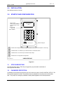
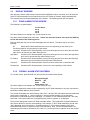
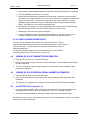
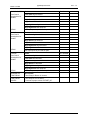
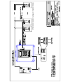
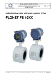
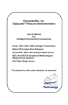
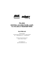
PG-2000
CENTRAL ACCESS PANEL (CAP)
For EC-GOLD TRANSMITTERS
User Manual
Technical Support
Continental North America Toll Free 1-(800) 387-9487
Ph: +1 (905) 829-2418 Fx: +1 (905) 829-4701
A Product of Arjay Engineering Ltd.
Oakville, Ontario, Canada
www.ArjayEng.com
www.EnmetGasDetection.com
PG-2000
Toxic Gas Monitor For Ventilation Control
Flexible monitoring and
control for ventilation of
toxic gas in parking
garages, warehouses and
maintenance facilities
The PG-2000 offers an intelligent solution to
gas monitoring and ventilation control. More
than 30 years of gas detection experience has
contributed to this highly functional monitor.
• central panel offers display and control
functions
• up to 128 sensors on one RS-485
communication run
• automatic weekly self test of sensors to
ensure safe and continuous monitoring
PG-2000
The PG-2000 control panel offers a keypad and LCD user interface for easy
set-up and operation. The Arjay microprocessor scans the field of sensors and
groups them into building zones for fan control.
EC-Gold sensors are used in the field for reliable and accurate monitoring of
the target gas. The carbon monoxide sensors have the unique capability to
generate a gas test daily to verify the sensor response.
Features and Benefits
Technical Specifications - Control Unit
• bright backlit display and large keypad
interface
• analog and relay outputs for control
interface
• wall mount heavy duty metal enclosure
• buzzer with silence button
• password protected calibration and
control functions
• 3 year sensor life guarantee, 5 year
expected life (CO sensor)
• weekly self gas test verifies sensor is
active (CO sensor)
• electrochemical sensors minimize
interference gases
• easy sensor mounting with external
calibration and test features
• relay expansion boards provide unlimited
relay and output functions
Backlit display offers detailed sensor
information.
Operating Temperature
Power Input
Standards
Enclosure
0˚C to 50˚C, indoor use
24 vdc, 110 vac or 220 vac
UL, CSA
Nema/Type 1
Technical Specifications - Sensor
Operating Temperature
Power input
Mounting
-20˚C to 40˚C, indoor use
24vdc, 0.1 amp each
surface mount, rear or top conduit
Standard Sensor gases available:
Carbon Monoxide, Hydrogen Sulfide, Chlorine, Ammonia and
Nitrogen Dioxide. Ask about our specialty gases.
The sensor offers easy plug-in wiring
connects and unique long life sensor.
Arjay SS-06
Arjay Engineering Ltd.
2851 Brighton Road
Oakville, Ontario
Canada L6H 6C9
tel
fax
N. America
email
web
++1 905-829-2418
++1 905-829-4701
1-800-387-9487
[email protected]
www.arjayeng.com
Model: PG-2000
pg2000capum45.DOC
Rev: 4.5
TABLE OF CONTENTS
1.0
2.0
3.0
4.0
5.0
6.0
INSTRUMENT OVERVIEW ............................................................................................3
1.1
FEATURES ........................................................................................................3
1.2
DESCRIPTION...................................................................................................3
1.3
SPECIFICATIONS .............................................................................................5
INSTALLATION...............................................................................................................6
STARTUP AND CONFIGURATION ...............................................................................6
3.1
STATUS INDICATIONS.....................................................................................6
3.2
PASSWORD PROTECTION .............................................................................6
3.3
DISPLAY SCREENS .........................................................................................7
3.3.1
ZONE ALARM STATUS SCREEN......................................................7
3.3.2
OVERALL ALARM STATUS SCREEN ...............................................7
3.3.3
AUXILIARY MODULE STATUS SCREEN..........................................8
3.3.4
ZONE ppm STATUS SCREEN ...........................................................8
3.3.5
mA MODULE STATUS SCREEN .......................................................8
3.3.6
INDIVIDUAL EC GOLD TRANSMITTER STATUS .............................9
3.4
NOTES ON THE USER INTERFACE ...............................................................9
3.5
SET NUMBER OF EC GOLD TRANSMITTERS ON NETWORK .....................9
3.6
SET ALARM VALUES, DELAYS AND RELAY MAP.........................................10
MISCELANEOUS SETUP ..............................................................................................12
4.1
CALIBRATION ...................................................................................................12
4.2
CALIBRATION USING EC GOLD PUSHBUTTON ...........................................12
4.3
CALIBRATION FROM THE CAP.......................................................................12
4.3.1 AUTOCALIBRATION ................................................................................12
4.3.2 OTHER CALIBRATION METHODS .........................................................13
4.4
VIEWING EC GOLD TRANSMITTER INFORMATION .....................................13
4.5
VIEWING EC GOLD REVISION/ SERIAL NUMBER INFORMATION ..............13
4.6
mA OUTPUT (from terminal 7, 8) ......................................................................13
BMCS ACCESS ..............................................................................................................14
5.1
SETUP ...............................................................................................................14
5.2
SERIAL CONFIGURATION ...............................................................................14
5.3
MODBUS ACCESS REGISTERS......................................................................14
5.3.1
MODBUS COMMANDS SUPPORTED...............................................14
5.3.2
REGISTER MAP .................................................................................14
SETTINGS SHEET .........................................................................................................15
-2-
Model: PG-2000
pg2000capum45.DOC
Rev: 4.5
1.0 INSTRUMENT OVERVIEW
1.1
1.2
FEATURES
•
Automatic scanning of up to 80 EC Gold network sensors.
•
Sensors may be assigned to any of 8 zones
•
Optional: two 4-20mA outputs per zone to reflect the zone’s max. and average ppm
•
Differential (dual threshold), independent, High-High, High, and Low alarms per zone.
•
Alarm thresholds may be independently set for up to 4 gases.
•
Optional 4 integral SPDT 10A relays plus up to 2 Auxiliary relay cards with up to 8 relays each.
Each relay is user selectable to be linked to any combination of 24 alarm sources: High-High,
High and Low alarms for all 8 zones. Relay1 can be designated for System Fault Alarm.
•
Standard Buzzer output linked to common High-High alarm, with Acknowledge input or mA
output for highest ppm level in place of buzzer (must request at time of order). Each Auxiliary
relay board also has a buzzer output and acknowledge input.
•
Independent Delay to On and Off for all installed relays
•
Delay to ON for buzzer alarm
•
RS-485 Modbus protocol to communicate with the EC Gold sensors
•
Optional 2nd RS-485 link to Building Monitoring & Control System (BMCS)
•
Front panel LCD and membrane keypad user interface.
DESCRIPTION
The CAP unit is field configured for the number of zones (up to 8) and sensors per zone.
Using the above setup information, the CAP unit continuously scans all the EC Gold transmitters for
their gas type and measured concentration. Up to 4 gas types are supported. For example, the CAP
may be configured to monitor Carbon Monoxide, Carbon Dioxide, Nitrogen Dioxide, and Methane.
The Low, High, and High-High alarm values are independently entered for each gas. A zone Low
alarm is triggered if the concentration of any of the target gases in that zone exceeds the Low alarm
value for that gas. There are a total of 24 possible alarms: Low, High, and High-High alarms per
zone for up to 8 zones.
The CAP supports 4 integral relays plus up to 2 Auxiliary boards each with 8 relays for a total of 20
relays. The CAP communicates with the Auxiliary boards via RS-485 / Modbus. The Auxiliary
boards may therefore be located conveniently to where they are required to reduce electrical wiring.
Each of the 20 relays may be independently mapped in the field to any of the 24 alarms (Low, High,
High-High for up to 8 zones). For example, Relay1 may be mapped to zone 1 Low Alarm as well as
the High Alarm for zones all other zones. Relay2 may be mapped to zone 2 Low Alarm as well as the
High Alarm for zones all other zones. This scheme will turn on the individual relays 1 and 2 when
their respective zones go into Low alarm, and both relays will turn on when any zone goes into High
or High-High alarm. This flexibility ensures efficient use of the relays, which can be tailored to unique
system requirements.
The common Trouble alarm is set if any EC Gold transmitter has a fault, or does not respond on the
network. Relay1 can be designated the common Trouble alarm relay.
Independent Delay to On and Delay to Off can be set for each relay.
-3-
pg2000capum45.DOC
Model: PG-2000
Rev: 4.5
For each zone, the maximum and average ppm values are calculated and transmitted on optional 420mA outputs.
RS-485 / Modbus link to BMCS
8 SPDT RELAYS
Aux Relay
Module
ENMET
CENTRAL ACCESS PANEL
(Scanner)
120VAC
8 SPDT RELAYS
Up to 16 mA Outputs
(2 per zone) **
first
ZONE 8
last
Aux Relay
Module
Max. EC Gold transmitters: 80
Max. Zones: 8
Any number of sensors per zone.
4 wire: 2 Network / 2 Power
!
RS485 connections must be daisy chained!
Sensors may be connected in any order but
must be daisy chained. NO STAR TAP WIRING
4 SPDT RELAYS
EC Gold tranmitters
Relays are user mappable to
any combination of zone alarms
**Optional 4-20mA outputs:
2 per zone (max8):
peak and average
ppm value per zone.
last
first
ZONE 1
Block.DSF
Figure 1.0
-4-
last
first
ZONE 2
pg2000capum45.DOC
Model: PG-2000
1.3
Rev: 4.5
SPECIFICATIONS
OPERATION
The CAP can access a maximum of 80 EC Gold transmitters assigned to up
to 8 zones and set Sensor Fault, High-High, High, and Low alarms based on
ppm values read from the transmitters. In addition, the maximum and
average ppm values are reflected on two optional 4-20mA outputs per zone.
USER INTERFACE
Calibration and setup
4 Line x 20 char LCD and 4X4 membrane keypad.
Network
RS-485 Modbus protocol connection to EC Gold sensors. Optional additional
serial port to link to a Building Automation System.
OUTPUTS
Alarms
Differential threshold Low, High, and High-High alarms per zone for up to 8
zones. Up to 4 gases are supported with independent Low, High, and HighHigh alarms for each gas type.
Common Sensor Fault alarm
Relay Contacts
4 Relays integral relays and up to 16 external relays in banks of 8. Each bank
of 8 is accessible via RS-485 and may be located where convenient to save
on wiring. Each relay may be field linked to any combination of 24 alarm
sources: High-High, High and Low alarms per zone for up to 8 zones. Relay1
may be designated as a System Fault alarm. Contacts are SPDT
10A/120VAC.
Alarm Delay
Independent Delay to On and Delay for each relay. Delay range: 0-100
minutes field adjustable.
Buzzer
Activated by any zone’s High-High alarm with acknowledge input. Each bank
of 8 relays also includes a buzzer and acknowledge input.
4-20mA Outputs
Optional. May be ordered in place of enclosure mounted buzzer or as a 4-20
mA output boards. Output boards are accessible via RS-485 and may be
located where convenient. 2 mA outputs per zone indicating max. ppm and
average ppm.
ELECTRICAL SPECIFICATION
Base Scanner Unit
Power
120VAC / 230VAC / 24VDC ±10% (specify at time of order), 15VA max.
Fuse
T160mA, 250VAC. Note: For 24VDC power input, the fuse is a 5mm x 20mm,
1/2A, Fast Blow type. This fuse is installed within the unit and must be
installed by qualified personnel only.
The equipment belongs to Pollution Degree2, Installation category II
Power from Scanner panel to EC Gold Transmitters
Power
24VDC / current depends on number of transmitters.
MECHANICAL SPECIFICATIONS
Enclosure
Nema 1 or 4X (optional) wall mount with clear cover to protect keypad / LCD
Dimensions
305mm (12") H, x 305mm (12") W x 101.5mm (4") D or
356mm (14") H, x 305mm (12") W x 203mm (8") D (Fiberglass)
Weight
PG-2000 (fiberglass)
6.25 kg (13.75lbs)
PG-2000 (Nema 1)
7.18 kg (15.8lbs)
ENVIRONMENTAL SPECIFICATIONS
Operating Temp.
0 - 55 Deg. C
Relative Humidity
90% max. with no condensation.
-5-
pg2000capum45.DOC
Model: PG-2000
2.0
Rev: 4.5
INSTALLATION
See drawings at back of manual.
3.0
STARTUP AND CONFIGURATION
RELAY LEDS
Relays may be linked to
any combination of zone
alarms
STATUS LED:
GRN = OK
RED = ERROR
R1
4 line x 20 char
LCD
R2
R3
R4
STATUS
DISPLAY
1
2
3
CAL
4
5
6
CONTROL
7
8
9
.
0
ENTER
SETUP
www.arjayeng.com
DISPLAY
CALIB
CONTROL
SETUP
Membrane keypad
DISPLAY KEY: Displays the different display and status screens. [Used as backspace in value entry]
CALIBRATE KEY: To calibrate any EC Gold transmitter on the RS-485 network.
CONTROL KEY: For CAP mA output and Alarm Relay settings.
SETUP KEY: For configuration and diagnostics.
HHospUSRINT.dsf
USER INTERFACE
Figure 3.0
3.1
STATUS INDICATIONS
One LED per Relay status. Each relay is triggered by any selectable combination of
zone High and Low alarms.
3.2
PASSWORD PROTECTION
A password must be entered to access any of the 3 value entry menus: CALIB, CONTROL, SETUP. The
factory default password is 2000. The password may be changed from the setup menu as described
later. The prompt for entering the password is always 9999 regardless of the actual password.
-6-
Model: PG-2000
3.3
pg2000capum45.DOC
Rev: 4.5
DISPLAY SCREENS
After powerup, and the initial startup screen has been displayed for about 3 seconds, the CAP scans all
active EC Gold transmitters on the network (as set by the "number of remotes" setting explained later.
This may take several seconds depending on the number. The following screen will now appear:
3.3.1
ZONE ALARM STATUS SCREEN
The following is a typical display:
z1: Low Alarm
z2: ok
z3: ok
z4: ok
The above display is for example only. Actual values will vary.
The alarm status is displayed for each zone . If there are more than 4 zones, then press the DISP key
to view the status of the remaining zones.
Each line starts with the zone number and displays the zone status. The status may be one of the
following:
Ok
Means all EC Gold transmitters in this zone are responding on the network, are
functioning properly, and are causing no gas alarms.
Low Alarm At least one EC Gold transmitter in this zone has a ppm level at or above the Low Alarm
ppm level for at least the Low Alarm Delay On time.
High Alarm
At least one EC Gold transmitter in this zone has a ppm level at or above the High Alarm
ppm level for at least the High Alarm Delay On time.
Hi Hi Alarm
At least one EC Gold transmitter in this zone has a ppm level at or above the High High
Alarm ppm level for at least the High High Alarm Delay On time.
Xmtr error
At least one EC Gold transmitter in this zone has a sensor fault or instrument fault.
No response
At least one EC Gold transmitter in this zone is not responding on the network.
3.3.2
OVERALL ALARM STATUS SCREEN
To view this screen, press the DISP key from the last Zone Alarm Status Screen.
Max ppm=25 by #5
Network : OK
Xmtrs
: OK
Alarm status: Low
The above display is for example only. Actual values will vary.
The top line displays the maximum ppm registered by any EC Gold transmitter in any zone, and also the
transmitter network address, which caused it.
The second line displays the network status: either “OK” if all active EC Gold transmitters and networked
resources are responding, or “Net no response: x” and the number (quantity) of not responding
transmitters or networked resources is displayed. For example if 1 EC Gold transmitter and 1 Aux relay
board and 1 mA output module are not responding then "Net no response: 2" is displayed.
The third line displays the common EC Gold transmitter status. This includes EC Gold transmitters that
have sensor faults or if they are not responding on the network. If all EC Gold transmitters are OK, then
“OK is displayed, else “Xmtr trouble: x” is displayed where “x” is the number (quantity) of EC Gold
transmitters with sensor or instrument faults or not responding. Note: if an EC Gold transmitter is not
responding then this will be indicated on line 2 and 3 i.e. you will get “Net no response” and “Xmtr trouble”
errors.
-7-
Model: PG-2000
pg2000capum45.DOC
Rev: 4.5
The bottom line displays the common alarm status. Based on the current alarm state, “OK”, “Low Alarm”,
“High Alarm”, or “High High Alarm” is displayed. The status reflects the alarm condition including user
settable time delays.
3.3.3
AUXILIARY MODULE STATUS SCREEN
To view this screen, press the DISP key from the Overall Alarm Status Screen.
Aux1:ok
Relays 1-8: 10000000
Aux2:ok
Relays 1-8: 00000001
The above display is for example only. Actual values will vary.
The status of the Auxiliary Relay module(s) is displayed. If only one Aux module is installed, then the
bottom 2 lines are blank.
“ok” means the Aux module is responding on the network.
The next line for each Aux module displays the individual status of each relay 1-8 installed on the Aux
module. From left to right for relays 1 to 8, a 1 indicates the relay is energized and a 0 indicates it is deenergized.
3.3.4
ZONE ppm STATUS SCREEN
To view this screen, press the DISP key from the Auxiliary Status Screen.
z1 Hi/Av:
z2 Hi/Av:
z3 Hi/Av:
z4 Hi/Av:
25(05)/ 3
12(11)/ 5
0(20)/ 0
0(32)/ 0
The above display is for example only. Actual values will vary.
The ppm status is displayed for each zone. If there are more than 4 zones, then press the DISP key
to view the status of the remaining zones.
Each line starts with the zone number. The first value is the highest ppm recorded for that zone together
with the transmitter network address causing this value. The average value for the entire zone is
displayed at the end of the line. In the example above, zone 1 has a high of 25ppm caused by EC Gold
transmitter # 5. The average for the zone is 3 ppm.
3.3.5
mA MODULE STATUS SCREEN
To view this screen, press the DISP key from the Auxiliary Module Status Screen. This screen is only
displayed if at least one mA module is installed. If more than 4 zones have mA modules then
press the DISP key to view the remaining zone mA status.
z1:MaxmA:ok
z2:MaxmA:ok
z3:MaxmA:ok
z4:MaxmA:ok
AvrgmA:ok
AvrgmA:ok
AvrgmA:ok
AvrgmA:ok
The above display is for example only. Actual values will vary. Only mA modules for installed zones are
displayed.
-8-
Model: PG-2000
pg2000capum45.DOC
Rev: 4.5
Each zone may have 2 mA modules: one for the max ppm in the zone and the other for the average ppm
value. If a mA module is not installed, then N/A is displayed. If it is responding on the network then “Ok”
is displayed. If it is not responding then “N/R” is displayed.
3.3.6
INDIVIDUAL EC GOLD TRANSMITTER STATUS
The status of individual EC Gold transmitters may be viewed by pressing the following keys on the
keypad while in any of the screens described above in sections 3.3.1 – 3.3.5:
Press the zone number to get to the corresponding zone sensor status. For example for zone 1 press
“1”. The ENTER key does not need to be pressed.
The status of individual EC Gold transmitters for the corresponding zone are displayed 15 at a time. If
more than 15 transmitters are assigned to the zone, then press the DISP key repeatedly to view the
status of remaining EC Gold transmitters, 15 at a time.
For each EC Gold transmitter, ppm value and its status is alternately displayed every second beside the
sensor number.
The status is displayed followed by a 2 letter code:
NR = no response from
ER = Instrument error
HH = This EC Gold transmitter has caused a High High Alarm
Hi = This EC Gold transmitter has caused a High Alarm
Lo = This EC Gold transmitter has caused a Low Alarm
Pressing the DISPLAY key when the last transmitter is on screen cycles back to the Main Display.
3.4
NOTES ON THE USER INTERFACE
When entering in numeric values, the cursor can be backspaced to correct mistakes by pressing the
DISPLAY key. This is only true if the cursor is not at the beginning of the displayed value, in which case
the DISPLAY menu is entered.
Values may be entered with any number of places of decimal.
If the entered value is out of the allowed limits, the system displays the limiting value for 2 seconds. For
example if a gas concentration Calibration value is entered as 5000.0 then MAX. 999 is displayed for 2
seconds then entry is allowed again. The current value is not changed unless the entered value is within
limits.
3.5
SET NUMBER OF EC GOLD TRANSMITTERS ON NETWORK
1. Press the SETUP key, enter the password at the prompt, then 1 for Zone / EC Gold transmitter setup
from the SETUP menu screen. The default factory set password is 2000.
2. Enter the total number of EC Gold transmitters on the network followed by the ENTER key. Note: this
value includes transmitters in all zones. The CAP unit assumes sequential addresses starting from 1
to the number entered. i.e. if 14 is entered then addresses 1 to 14 are considered active.
3. Next, at the prompt, enter the number of zones require (maximum is 8).
4. At the prompt for each zone, enter the start and end transmitter network addresses for each zone.
Any number transmitters may be selected for a zone as long as they have sequential network
addresses. Also, the end address must always be greater than the start address. For example zone
1 addresses 1-5, zone 2 addresses 6-14 and so on.
-9-
Model: PG-2000
3.6
pg2000capum45.DOC
Rev: 4.5
SET ALARM VALUES, DELAYS AND RELAY MAP
1. Press the CONT key then press 1 for Gas Alarms / mA Span. If coming from the normal display
screens, enter the password at the prompt. The default factory set password is 2000.
2. Select a number (1-4) to select a gas with which to associate alarm thresholds. For example in a
system with CO and NO2 EC Gold transmitters, Gas#1 is set for CO and Gas#2 for NO2. Gases #3
and 4 are set to Unused 9 (code 23).
3. After pressing a Gas number, select the gas type by pressing a 2 digit gas code from 0 to 23 followed
by the ENTER key. For each code entered, the corresponding gas is selected, with a prompt to
press 1 to keep the selection or 2 to select another gas. The supported gases and their
corresponding codes are shown below:
GAS NAME
CODE
Carbon Monoxide: CO (ppm)
00
Nitrogen Dioxide: NO2 (ppm)
01
Methane: CH4 (%LEL)
02
Propane: C2H5 (%LEL)
03
Hydrogen Sulfide: H2S (ppm)
04
Ammonia: NH3 (ppm)
05
Chlorine: Cl (ppm)
06
Oxygen: O2 (%)
07
Gasoline (%)
08
Hydrogen: H2 (ppm)
09
Toxic (ppm) – generic name
10
Combustible (%LEL) – generic name
11
BRH (Broad Range Hydro Carbon) (ppm)
12
Carbon Dioxide: CO2 (ppm)
13
Acetylene (ppm)
14
Sulfur Dioxide: SO2 (ppm)
15
ClO2 (ppm)
16
Hydrogen Chloride: HCl (ppm)
17
Hydrogen Cyanide: HCN (ppm)
18
Ozone: O3 (ppm)
19
Nitric Oxide: NO (ppm)
20
Temperature in deg. C
21
Temperature in deg. F
22
NOT USED
23
Table 3.1
- 10 -
Model: PG-2000
pg2000capum45.DOC
Rev: 4.5
4. After selecting the desired gas by pressing 1 in step above, enter the high and low thresholds for the
Low Alarm. The gas concentration must rise above the high threshold to set the Low Alarm, and
must fall below the low threshold to clear the Low Alarm.
5. After setting the Low Alarm thresholds, the system automatically prompts for the High and High-High
alarms thresholds.
6. Enter the full-scale value in ppm of CO for the 4-20mA output. This Span value applies to all of the
optional mA module outputs (High and Average ppm per zone, High ppm overall).
7. From the main Control menu, press 2 to set the Relay On and Off delays.
8. Next select either 1 for Buzzer delay, 2 for integral Relay delays (for relays 1 – 4), or 3 and 4 for Aux1
relays and Aux2 relays respectively.
9. The Buzzer only has a On delay. For the Integral or Aux relays, next select the relay number (1-4) for
Integral relays and 1-8 for Aux relays. Enter the On and Off delays for each relay. The values are in
minutes. Fractional minutes are allowed i.e. 1.5 minutes can be entered.
10. From the main Control menu, press 3 to set the Relay Map. Each of the installed relays may be
linked to any combination of up to 24 alarm sources: High-High, High and Low alarms for 8 zones. In
addition, Relay1 may be designated as a System Fault alarm.
11. The unit prompts if Relay1 is desired for System Fault alarm:
FAULT RELAY
Set Relay1=Sys Fault
Press 1 to toggle
Yes
12. The bottom line displays the current setting (Yes means Relay1 is set for System Fault alarm). If
necessary, press 1 to change this value, then press the ENTER key.
13. Press the ENTER key after reading the description screen. A screen similar to the following is
displayed. The map shown is an example only. The actual values will vary. This screen shows the
map for Integral Relays 1 and 2 (R1 and R2). Note: the “Int” on top of the Relay column indicates
that the relay is part of the Integral relay group. Aux1 and Aux2 are displayed when setting Aux
relays. If the Integral Relay1 has been set for System Fault, then it is excluded from other alarms.
The column headings are for the Low (L), High (h), and High-High (H) alarms for each zone (z1 to
z4). Enter the mapping as follows:
z1 z2 z3 z4
Int LhH LhH LhH LhH
R1 YNY NNY NNY NNY (or “Fault Relay”)
R2 NNY YNY NNY NNY
14. The cursor starts at the Low alarm column for zone 1. To establish a link: press 1, to clear the link:
press 0. If there are more than 4 zones then complete the entries for the first 4 zones for each relay
and the remaining zones are automatically displayed. Unused zones are not displayed. To advance
the cursor to the next column with no change: press the ENTER key. To advance to the next screen:
press any other numeric key. Note: changes are made as soon as the ‘1’ or ‘0’ key is pressed. If a
mistake is made, you will need to exit the menu, then re-enter to change the value.
15. After completing the maps for relays 1 and 2, the system automatically prompts with the maps for all
remaining relays.
THIS CONCLUDES THE CAP SETUP. FOR SETTING UP / CALIBRATING
INDIVIDUAL EC GOLD TRANSMITTERS, REFER TO THE NEXT SECTION.
- 11 -
Model: PG-2000
4.0
pg2000capum45.DOC
Rev: 4.5
MISCELANEOUS SETUP
Each remote EC Gold transmitter may be individually setup and calibrated via the CAP unit. Setup from
the CAP is more convenient than using the EC Gold integral switches. Calibration, on the other hand, is
usually best done at each EC Gold since the sensor has to be gassed. A handheld calibrator may be
purchased for easy calibration.
NOTE: The CAP acts as a user interface to the remote EC Gold transmitter being
calibrated. The resulting setup and calibration values reside in EC Gold transmitter and
not in the CAP.
4.1
CALIBRATION
The EC Gold transmitter is pre-calibrated at the factory, but field verification with a known
concentration of test gas should be performed to ensure proper operation of the system. Field
calibrations should be scheduled every 3 or 4 months as part of a regular maintenance program.
The EC Gold transmitters may be calibrated either using the CAP or at the EC Gold itself using the
convenient single point pushbutton procedure. The latter method is quickest since calibration involves
exposing the sensor of the EC Gold transmitter with a calibration gas i.e. the procedure requires
someone to fit the calibration cup over the EC Gold’s sensor housing.
Calibration via the CAP is practical if there are 2 people equipped with 2 way radios calibrating the EC
Gold transmitters (one at the CAP and the other gassing the sensors).
4.2
CALIBRATION USING EC GOLD PUSHBUTTON
To calibrate the EC Gold transmitters using their integral calibration pushbutton, refer to the EC Gold
manual for the latest calibration procedure information.
4.3
CALIBRATION FROM THE CAP
The following procedure describes how to individually calibrate any remote EC Gold transmitter from the
CAP unit. As mentioned earlier, this method is most convenient if performed by 2 people communicating
via radio transceivers. This method is also preferred if the calibration gas can be selectively applied to
the EC Gold transmitters via tubing from a centrally located calibration gas canister. In this scenario, one
person can conveniently perform calibration.
The following procedure is for calibrating from the CAP panel and applies to either of the 2 methods (2
people or a single person with control over calibration gas to remote transmitters).
1. If not at the main Remote Setup Menu, press the CAL key, then enter the password at the prompt.
The factory set password is 2000.
2. Press 1 for Calibration from the Calibration menu
3. Select the Address of the desired EC Gold transmitter to be calibrated.
4. The calibration menu offers 3 types of calibration: auto cal, manual cal and direct entry of the slope
and offset.
4.3.1 AUTOCALIBRATION
Autocal is the most common form of calibration. In this procedure, the gas sensor is
exposed to 2 different gas concentrations in turn – one of which can be clean air (0
ppm CO). The concentration value is entered for each. The EC Gold is then
instructed to calculate the required calibration parameters.
1. Press the CAL key to enter the EC Gold Setup menu.
2. Press 1 for Sensor CAL.
- 12 -
Model: PG-2000
pg2000capum45.DOC
Rev: 4.5
3. At the prompt, enter the address number of the desired EC Gold transmitter to be calibrated.
4. From the Calibration menu press 1 for Autocal.
5. Gas the EC Gold sensor being calibrated with the first gas. Ambient air can be used as 0
ppm ONLY if it is certain that there is no CO in the air. Enter the concentration of the first gas
in ppm for this first point. The bottom line displays the raw sensor reading in mV and is
displayed to give an indication when the reading has settled. This typically takes about 1
minute. Press Enter to confirm the first calibration point.
6. This display now prompts for the second calibration point. Remove the first calibration gas
and let the sensor settle in air until the reading returns to clean air levels.
7. Repeat step 5 with the second gas concentration.
8. In case of calibration errors such as low sensor sensitivity, or user entry errors, an error
message is flashed for about 2 seconds after the ENTER key has been pressed.
4.3.2 OTHER CALIBRATION METHODS
There are 2 other methods. Both require a prior successful autocal. The first
method allows manual entry of 4 points: the concentration and raw sensor values for
each of 2 cal points. The EC Gold is then instructed to calculate the required
calibration parameters.
The final cal method is to directly enter the calibration values i.e. the SLOPE
sensitivity) and the OFFSET (or raw value in 0 ppm CO).
4.4
VIEWING EC GOLD TRANSMITTER INFORMATION
1. Press the SETUP key then 2 for Xmtr Information.
2. Press 1 for the Sensor Values / Stat menu, then at the prompt, enter the address of the desired
EC Gold transmitter.
3. The CO concentration in ppm, the sensor signal in mV and Status for the selected EC Gold
transmitter is displayed.
4.5
VIEWING EC GOLD REVISION/ SERIAL NUMBER INFORMATION
1. Press the SETUP key then 2 for Xmtr Information.
2. Press 2 for the Revisions /ID, then at the prompt, enter the address of the desired EC Gold
transmitter.
3. The Software rev., Hardware rev., and serial number of the selected EC Gold are displayed.
4.6
mA OUTPUT (from terminal 7, 8)
1. mA output may be ordered in place of enclosure mounted buzzer. Ma output is based on the
highest ppm and the span is set in the control setting. See 3.6.6 for setting mA Span.
2. mA outputs are also available by ordering mA Output Boards or from Auxillary Boards.
No mention of How to set up mA outputs as well as select CH1 output instead of buzzer. No mention
of viewing mA output with key # 9.
- 13 -
pg2000capum45.DOC
Model: PG-2000
5.0
Rev: 4.5
BMCS ACCESS
The Enmet CAP's (Central Access Panels or Scanners) may be accessed via an RS-485 link using the
Modbus protocol. Up to 28 CAP units may be connected on a single network – in this case only 2 are
connected. The BMCS acts as a Modbus master.
5.1
SETUP
Each CAP unit must be given a unique Address so it can be specifically be accessed by the BMCS. This
is done as follows:
5.2
•
Press the Setup key on the CAP keypad.
•
Press 3 for Cap Configuration.
•
Press 3 for CAP Net Address.
•
Enter the desired Address. This value is typically already set at the factory starting at 1 and
increasing incrementally for additional CAP units in the system.
SERIAL CONFIGURATION
2 Wire RS-485 (1/2 Duplex)
9600 Baud, Even parity, 8 Data bits, 1 stop bit.
For connection to a PC, an RS-485 to RS-232 converter module may be used. This module plugs into
the PC’s serial port and provides a 2 wire RS-485 connection. For convenience, a port-powered
converter should be used.
The following RS-485-232 converter has been tested with the system:
Model: 485SD9TB (Manufacturer: B&B Electronics )
5.3
MODBUS ACCESS REGISTERS
The Enmet CAP is a Read Only device i.e. the BMCS can only read, but not modify information in the
CAP.
5.3.1
MODBUS COMMANDS SUPPORTED
Read Holding Registers (Modbus command # 3)
Other modbus commands are NOT supported.
5.3.2
REGISTER MAP
The main information intended for the BMCS is the highest ppm concentration read
by the CAP from any EC Gold transmitters networked to it. This information is used
by the BMCS to control the ventilation fan speed.
This MAX PPM value is in IEEE754 format, which is 4 bytes or 2 consecutive
modbus registers. The packing is as follows:
Floating point value (before transmission):
Byte 3 (Most Sig. Byte)
Byte 2
Byte 1
Byte 0 (Least Sig. Byte)
As Sent: (First to last): Byte 1, Byte 0, Byte 3, Byte 2.
i.e. Byte 1 is sent first followed by Byte 0, then Byte 3 and finally Byte 2.
If 2nd second serial port is purchased, see attached “Scanner Modbus MAP”
- 14 -
pg2000capum45.DOC
Model: PG-2000
6.0
Rev: 4.5
SETTINGS SHEET
Checked by
Model Number
Serial Number
Hardware Rev.
Software Rev.
The factory settings column below lists the typical default settings. The user may change these values. If
changed, please fill in the USER SETTING column for future reference.
PARAMETER
Number of Sensors
Number of Zones
DESCRIPTION
SETTING
SETTING
Zone 1(eg.1-6)
Zone 2(eg.7-12)
Zone 3
Zone 4
Zone 5
Zone 6
Zone 7
Zone 8
GAS ALARM / mA SPAN
GAS #1 ALARM
Code
SPAN
USER
Total number of sensors in the system
Total number of zones
Zone
configuration
( Sensor numbers
per Zone)
Alarms may be
set for up to 4
gases. Alarms
are checked
based on the gas
type setting in EC
Gold Transmitters.
For example, in a
system with EC
Gold transmitters
for CO and NO2,
enter separate
alarm values for
CO (Gas #1) and
for NO2 (Gas #2).
Gases #3 and #4
are set to
UNUSED
FACTORY
0 = CO
Low Alarm high threshold – concentration of any EC
Gold transmitter in the zone must exceed this value for
at least the the Low Alarm delay to ON period to activate
the Low Alarm.
Low Alarm low threshold – concentration of all EC Gold
transmitters in the zone must fall below this value for at
least the Low Alarm delay to OFF period to de-activate
the Low Alarm
High Alarm high threshold. As per Low Alarm
thresholds description
High Alarm low threshold. As per Low Alarm
thresholds description.
High High Alarm high threshold. As per Low Alarm
thresholds description
High High Alarm low threshold. As per Low Alarm
thresholds description
This is used if ordered in place of enclosure mounted
buzzer. Must be ordered at time of order. This is also
used on the optional Auxillary Board. There are up to 2
per board to reflect the maximum gas concentration in
the zone. The full Scale concentration in ppm.
- 15 -
pg2000capum45.DOC
Model: PG-2000
GAS #2 ALARM
Code
See Gas #1
descriptions for
details
Low Alarm high threshold
Rev: 4.5
23 = Unused
Low Alarm low threshold
High Alarm high threshold
High Alarm low threshold
High High Alarm high threshold
High High Alarm low threshold
SPAN
mA output span as per GAS #1 span
GAS #3
Code
See Gas #1
descriptions for
details
Low Alarm high threshold
23 = Unused
Low Alarm low threshold
High Alarm high threshold
High Alarm low threshold
High High Alarm high threshold
High High Alarm low threshold
SPAN
mA output span as per GAS #1 span
GAS #4
Code
See Gas #1
descriptions for
details
Low Alarm high threshold
23 = Unused
Low Alarm low threshold
High Alarm high threshold
High Alarm low threshold
High High Alarm high threshold
High High Alarm low threshold
SPAN
mA output span as per GAS #1 span
BUZZER ON
HI/ HI Alarm
TIME DELAY
Time Delay for Buzzer in minutes
TIME DELAY
Time delay set to 0 at factory.
NOTES
To be set at proper values at START_UP.
- 16 -
pg2000capum45.DOC
Model: PG-2000
Rev: 4.5
Relay Mapping (Circles specifys the factory setting of "YES" as per job specification)
−
Relay Mapping is set in #3 of Control Menu;
−
Time Delay is set in #2 of Control Menu;
−
If Internal Relays are not purchased, the Leds on the Control Box may be set as per GAS level
for Led indication.
Zone
1
Zone
2
Zone
3
Zone
4
Zone
5
Zone
6
Zone
7
Zone
8
R1
NNN
NNN
NNN
NNN
NNN
NNN
NNN
NNN
R2
NNN
NNN
NNN
NNN
NNN
NNN
NNN
NNN
R1 set for Fault
R3
NNN
NNN
NNN
NNN
NNN
NNN
NNN
NNN
YES / NO
R4
NNN
NNN
NNN
NNN
NNN
NNN
NNN
NNN
R1
NNN
NNN
NNN
NNN
NNN
NNN
NNN
NNN
R2
NNN
NNN
NNN
NNN
NNN
NNN
NNN
NNN
R3
NNN
NNN
NNN
NNN
NNN
NNN
NNN
NNN
R4
NNN
NNN
NNN
NNN
NNN
NNN
NNN
NNN
R5
NNN
NNN
NNN
NNN
NNN
NNN
NNN
NNN
R6
NNN
NNN
NNN
NNN
NNN
NNN
NNN
NNN
R7
NNN
NNN
NNN
NNN
NNN
NNN
NNN
NNN
R8
NNN
NNN
NNN
NNN
NNN
NNN
NNN
NNN
R1
NNN
NNN
NNN
NNN
NNN
NNN
NNN
NNN
R2
NNN
NNN
NNN
NNN
NNN
NNN
NNN
NNN
R3
NNN
NNN
NNN
NNN
NNN
NNN
NNN
NNN
R4
NNN
NNN
NNN
NNN
NNN
NNN
NNN
NNN
R5
NNN
NNN
NNN
NNN
NNN
NNN
NNN
NNN
R6
NNN
NNN
NNN
NNN
NNN
NNN
NNN
NNN
R7
NNN
NNN
NNN
NNN
NNN
NNN
NNN
NNN
R8
NNN
NNN
NNN
NNN
NNN
NNN
NNN
NNN
Relay
INT
AUX1
AUX2
- 17 -
Time
Delay on
(min)
Time
Delay off
(min)