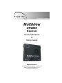
1
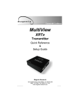
.
MultiView
XR2000
Receiver
Quick Reference
&
Setup Guide
Magenta Research
128 Litchfield Road, New Milford, CT 06776 USA
(860) 210-0546 FAX (860) 210-1758
www.magenta-research.com
1
MAGENTA MULTIVIEW™ SERIES
© 1998-2009 by Magenta Research All rights reserved.
Magenta Research
128 Litchfield Road
New Milford, CT 06776 USA
This document and the Magenta Research products to which it relates, and the copyright
in each, is the property of Magenta Research. Neither the document nor the products may
be reproduced by any means, in whole or in part, without the prior written permission of
Magenta Research. Magenta Research makes no warranty or representation, either express
or implied, with respect to this software or documentation, including their quality,
performance, merchantability, or fitness for a particular purpose. As a result, this software
or documentation are licensed "as is" and you, the licensee, are assuming the entire risk as
to their quality and performance.
In no event will Magenta Research be liable for direct, indirect, special, incidental, or
consequential damages arising out of the use of or inability to use the software or
documentation.
Magenta Research and the Magenta Research logo are trademarks of Magenta Research.
All other brands, product names, and trademarks are the property of their respective
owners.
2
FCC/IC RFI STATEMENTS, EU DECLARATION OF CONFORMITY.
FEDERAL COMMUNICATIONS COMMISSION
AND
INDUSTRY CANADA
RADIO FREQUENCY INTERFERENCE STATEMENTS
This equipment generates, uses, and can radiate radio-frequency energy, and if
not installed and used properly, that is, in strict accordance with the manufacturer’s
instructions, may cause interference to radio communication. It has been tested
and found to comply with the limits for a Class A computing device in accordance
with the specifications in Subpart B of Part 15 of FCC rules, which are designed to
provide reasonable protection against such interference when the equipment is
operated in a commercial environment. Operation of this equipment in a
residential area is likely to cause interference, in which case the user at his own
expense will be required to take whatever measures may be necessary to correct
the interference.
Changes or modifications not expressly approved by the party responsible
for compliance could void the user’s authority to operate the equipment.
This digital apparatus does not exceed the Class A limits for radio noise emission
from digital apparatus set out in the Radio Interference Regulation of Industry
Canada.
EUROPEAN UNION DECLARATION OF CONFORMITY
The manufacturer declares that this product meets the requirements of
EU Directive 89/336/EEC.
3
1
MAGENTA MULTIVIEW™ SERIES
Contents
Chapter
Page
1.
Specifications...................................................................................................3
2.
Introduction ........................................…..........................................................4
2.1 Overview.....................................................................................................4
2.2 Equipment You May Also Need..........................................................…....4
2.3 Compatible Cabling ........................................................................…...….4
3. Setup and Installation..........................................… ......................................….5
3.1 Data Mode Configuration..............................................................................5
3.2 Cabling Considerations................................................................................5
3.3 Making the Connections................................…............................................5
3.3.1 Connections and Setup in General .......................................……......5
3.3.2 Connections on the Single-Port VGA/Audio……..............………..…..6
3.3.4 Connections on the Single-Port SA/SAP version……………...………7
3.4 Video Adjustment……..................................….........................................….8
3.4.1 Cable Distance Compensation Settings..................................…….….8
3.4.2 Skew Compensation Settings.............................................………..….9
4. Troubleshooting..................................................................................................10
4.1 Common Problems ......................................................................................10
Appendix A. Cabling Pinouts.........................................…......................................12
Appendix B. XR-2000 Configuration Settings……….......…....................................14
Appendix C. Setting Sync Modes………………………...........................................16
Appendix D. Skew Module………….......................................................................17
Appendix E. Mounting Options...............................................................................18
Appendix F. Pollable Serial Mode......................................................................….19
4
2
CHAPTER 1: Specifications.
1. Specifications
Cable Required: Category 5, 5e, 6 shielded or unshielded twisted pair
Compliance:
CE; FCC Class A, IC Class A
Video Support: QVGA, VGA, SVGA, XGA, SXGA, UXGA, RGBHV, RGB,
Composite (NTSC, PAL, SECAM), S-Video, Component Video,
widescreen modes, HDTV modes including 1080p, 1080i, 720p
Resolution and
Refresh Rate:
At 2000 ft. (609 m) or less: to 1920x1200
Required Source
Impedance:
Video OUT: 75 ohms;
Audio models: Audio OUT (if any): 600 ohms maximum
Required Destination
Impedance:
Video IN: 75 ohms;
Audio models: Audio IN (if any): 600 ohms minimum
Audio
Characteristics: Right/Left summed (A option)
XR2000SA/SAP: Full Stereo
Line Level 600 Ohm Unbalanced
Serial
Characteristics: Protocol: Asynchronous; transparent to data format;
data rates to 115 kbps simplex, half-duplex modes
SA/SAP versions are 3 wire, fixed baud rate of 9600
Connectors:
Temperature
Tolerance:
Humidity
Tolerance:
(1) 4 pin phoenix, (2) RJ-45, (1) HD15 F; (1) DB9M (model
dependent)
Operating: 32 to 104°F (0 to 40°C);
Storage: -4 to +140°F (-20 to +60°C)
Up to 80% noncondensing
Enclosure:
Power:
Steel
+12 VDC; 1.2 A
Consumption: 6 watts maximum
Size:
1.2"H x 5.6"W x 6.2"D (3.0 x 14.2 x 15.7 cm)
Weight:
2.0 lb. (0.9 kg)
5
3
MAGENTA MULTIVIEW™ SERIES
2. Introduction
2.1 Overview
The Magenta MultiView Series extends video, audio and serial signals over ordinary
Category 5 cable.
This manual covers Magenta MultiView Series XR2000 Receivers. These units are field
configurable for various video, audio and serial options. See Appendix B for
configuration settings.
SA series feature video, stereo audio and RS-232 signals on a single cat5.
SAP series units are similar to the above but have additional features for pollable serial.
The Magenta MultiView Series XR Receivers feature optional integrated skew
compensation that can be varied in 2 ns increments to 65 ns total per color channel to
cancel the effects of skew in Category cables. This feature allows you to use CAT5e
and reduced-skew CAT6 cables to lengths up to 2000 ft.
For information on the respective transmitter unit, please refer to the appropriate
manual included with the transmitter.
All models support refresh rates/resolutions up to 1920 x 1200 @ 60 Hz to 2000 feet
(609 m) and 2048 x 1536 @ 70 Hz to 1000 feet (305 m).
WARNING
This equipment is not intended for, nor does it support, distribution
through an Ethernet network. Do not connect these devices to any sort
of networking or telecommunications equipment!
2.2 Equipment You May Also Need
• Audio cable with RCA jacks.
• Video cable with HD15 connectors
• Serial cable with DB9 connectors.
• CAT5 cable.
2.3 Compatible Cabling
Magenta Research products are compatible with Cat5/5e/6 data cabling as well as
skew free CAT5/5e cabling manufactured for video applications. Note that some skew
free Cat5 is specific to a particular vendor and is not compatible with our products.
Please ensure any skew free CAT5 cable is non-proprietary prior to purchase/
installation.
CAT6 cable, due to the manufacture method, can exhibit much greater skew than
standard CAT5/5e and may require skew compensation beyond what the standard
product offers. Please contact Magenta Research for assistance.
CAT5/5e/6 cabling for the Magenta MultiView Series must be pinned to the TIA-EIA
T568B wiring specification (see appendix A) We also highly recommend that all CAT5
cables be pre-terminated and tested. Cables terminated on-site or in an existing
infrastructure should be tested before use to ensure compliance with the TIA-EIA
T568B specification. Using incorrectly terminated CAT5 cables can damage the
Magenta MultiView Series.
.
6
4
CHAPTER 3: SETUP & INSTALLATION.
3. Setup and Installation
3.1 Data Mode Configuration
SA series offer RS232 serial in addition to stereo audio. The serial signal is 3 wire TX,
RX, GND and does not support full modem signals. Baud rates for the SA series are
fixed at 9600. Simplex modes are supported without jumper or other changes by simply
using the TX signal only. SA units require no configuration.
SAP series offer pollable RS232 serial in addition to stereo audio. The serial signal is 3
wire TX, RX, GND and does not support full modem signals. Baud rates for the SAP
series are fixed at 9600. Simplex modes are supported without jumper or other changes
by simply using the TX signal only. See Appendix F on configuration and use of SAP
Series.
3.2 Cabling Considerations
• We recommend mounting and connecting all cabling to the Magenta MultiView Series
components before applying power.
• Makes sure that the CAT5 cable you intend to use has been tested to comply
with the TIA/EIA 568B wiring specification (See Appendix A).
3.3 Making the Connections
3.3.1 CONNECTIONS AND SETUP IN GENERAL
This section contains figures showing connections with the specific Magenta MultiView
Series models. In general, however, the connection and setup procedure at both
transmitter and receiver ends is as follows:
NOTE: all units must be the same type for all supported features to function correctly.
For example, a UTX set for R/L summed audio must be connected to an XR2000 set for
R/L summed audio. Similarly, A UTX SA cannot be used with an XR2000A. Video
modes may function normally, but 4th pair options will not.
At the transmitter end (refer to the transmitter user guide) :
1. Connect the source video to the Magenta MultiView Series transmitter video input
port, which is an HD15 connector labeled SOURCE IN.
2. If desired, attach a local monitor via the local monitor port to LOCAL OUT
3. Make your audio or serial connections via the phoenix connector or DB9 connector
as appropriate.
7
5
MAGENTA MULTIVIEW™ SERIES
4. Connect the CAT5 cable to the transmitter.
5. Apply power on the transmitter. The LED should light and, if there’s a local
monitor attached, a video image should appear on the monitor’s screen.
At the receiver end:
1. Connect the VIDEO OUT HD15 connector to the display unit, and attach
any audio (AUX I/O) or serial connections (IOIO) depending on the model of MultiView
CAT5 Video System.
2. Connect the CAT5 cable to the LINK INPUT connection. If daisy chaining units,
connect the output CAT5 cable to the LINK OUTPUT connection.
3. Apply power. **NOTE: XR2000 units utilize 12VDC ** The LED should light and
video should appear on the display (make sure display is powered ON).
4. To adjust video levels and skew compensation see Section 3.4.
5. Please mount the XR2000 in a location that ensures the ventilation holes and fan are
not blocked.
3.3.2 CONNECTIONS ON THE SINGLE-PORT VGA/AUDIO
The single-port units with audio support video and audio signals over CAT5 cable. The
audio signal is line-level summed Right/Left audio, and powered speakers are required.
Note that there’s a single connection for audio input. You can also use the transmitters
and receivers to make video-only connections without audio. Figure 3-1 shows the
Single-Port MultiView CAT5 Video System with Audio Transmitter connections, and
Figure 3-2 shows the receiver connections.
Figure 3-1. Connections on the XRTx Universal Transmitter.
Figure 3-2. Connections on the XR2000 for video and audio.
8
6
CHAPTER 3: Setup and Installation.
3.3.3 CONNECTIONS ON THE SINGLE-PORT VGA SA and SAP
The Single-Port MultiView™ CAT5 Video System SA/SAP series supports RS-232,
video and stereo audio signals over CAT5 cable. SAP offers pollable serial modes so a
bi-directional serial session can be established with a receiver in a daisy chain.
At this time the Magenta MultiView units that support the SA/SAP versions are the
Magenta MultiView XRTx Universal Transmitter, AK600, AK1200,and XR2000
receivers. The Magenta MultiView T4, T5 transmitters do not support SA/SAP versions.
In order to utilize the full potential of the Magenta MultiView SA/SAP series, all
transmitters and receivers must be SA/SAP versions.
You cannot connect a standard RS232 or L/R audio version to an SA/SAP version to
get a single serial or audio signal. Video modes are not affected by this.
Serial signals are 3 wire RS232 (Tx, Rx, ground) and fixed at 9600 baud. Full 9 pin
modem signals are not supported.
Note when using the Magenta MultiView SA/SAP series with a MultiView 9D Cat5 DA,
or Cat5 matrix switch, the serial is transmit only. There are no configuration changes
required to the units. The serial application in use should be changed to transmit only.
Audio is full stereo, line level. One or two separate channels of mono audio may also
be used.
See figures below for cabling connections.
Appendix F details the configuration and use of the SAP series.
Figure 3-3: SA & SAP connections
NOTE
SA units are pre-configured from the factory and require no configuration
changes. SAP Units require unique addresses when pollable serial is used. See
Appendix F.
9
7
MAGENTA MULTIVIEW™ SERIES
3.4 Video Adjustment
3.4.1 Cable Distance Compensation Settings
In order to get the highest quality video signals from your MultiView CAT5 Video
System , please follow the instructions and diagrams below:
An Image Adjustment Utility is available for download from:
http:// www.magenta-research.com/test
Simply open in any image browser on a computer.
If the image file can not be downloaded, use a utility to draw a black box on a white
background.
NOTE: TURN KNOB SLOWLY DURING ADJUSMENT PROCEDURE. Turning too
fast may result in missing the proper EQ setting resulting in picture loss.
To Reset EQ and Skew values to 0, remove power from XR2000, Push and hold
EQ/Skew Knob in and re-apply power.
1.
Push EQ/Skew knob in once so that all three RGB LED’s are on with red, green,
and blue colors.
2.
Turn the EQ/Skew knob clockwise until the shadow next to the black box just
disappears. The brightness in the white area should be the same as the white area
above and below the black box. The Cable Length LED’s will turn on for indicated
cable distances. Starting from zero feet to 1,000 and above may take some time.
Please continue turning the knob for best picture quality.
3.
Press and release EQ/Skew knob until RGB LEDs are all off.
Adjust
Knob
LEDs for
Skew adjustment
Cable length
LEDs
Figure 3-9: Adjustment locations
Figure 3-4: Image Adjustment Utility—Cable Length EQ
10
8
CHAPTER 3: Setup and Installation.
3.4.2 Skew Compensation Settings
The XR2000 receiver is available with an optional skew compensation module to adjust
for signal timing differences due to differing pair lengths within the CAT5 cable. Using
the delay signals, skew may be compensated from 2 to 65 nanoseconds in 2
nanosecond increments on each individual color pair.
If skew compensation is required, but the skew comp module is not installed, call for
technical assistance.
An image file is available to assist in these settings (see Section 3.4.1 for details). See
Figure 3-5 for an example.
1.
2.
3.
To adjust individual colors, press the EQ/Skew knob until the desired color LED is
on for the RGB Skew LEDs to the left of the cable length LEDs. The R LED is for
the Red color channel, G LED is for green and the B LED is for blue.
Using the image utility, turn knob to add/subtract delay timing until a single
vertically aligned line of red, green, blue is obtained.
When complete press EQ/Skew knob until RGB LEDs are all off.
Not all colors will have the same delay settings.
Figure 3-5: Image Adjustment Utility—Skew
11
9
MAGENTA MULTIVIEW™ SERIES
4. Troubleshooting
4.1. Common Problems
In most cases, nearly every issue with the MultiView CAT5 Video System can be
resolved by checking the CAT5 termination and making sure that it’s pinned to the
TIA/EIA 568B wiring specification. However, there may be other problems that
cause the system to not perform as it’s designed. Below are solutions to the most
common installation errors.
Problem:
Solution:
No video signal at the transmitter local port or at the receiver.
• Check that both units are powered.
• Ensure EQ adjustment is set correctly — turn knob slowly.
• Make sure the CAT5 cable is terminated correctly per the
TIA/EIA 568B wiring specification.
• Is the display device powered on and functioning?
Check to ensure display settings (resolution, refresh rate, etc) are
compatible with input signal.
Problem:
Solution:
Poor video quality:
• Have all receiver adjustments been finished (see section 3.4).
• Ensure EQ adjustment is set correctly — turn knob slowly.
• Check all cable connections.
• The video signal’s refresh rate may be set too high. Reset to a
lower refresh rate in your monitor-configuration menu.
• There may be a delay skew issue. See Section on Skew.
Problem:
Solution:
Poor audio quality:
• Powered speakers are required. Make sure speaker power is
ON.
• Check input source levels from the source device. Make sure
the audio source is not overdriven or underdriven.
• Audio is summed left and right for “A” versions. If using a single
channel, both audio inputs must be connected at the transmitter
end for full audio gain. Audio is line level.
• If Daisy Chaining, audio termination must be removed in DP
units. Only the last receiver requires termination. Set the external
TERM switch to ON/OFF as required. This does not apply to SA or
SAP units (SA units no longer require separate daisy chain or end
of line units as of April 2009).
• If Daisy Chaining, audio termination must be removed in DP
units. Only the last receiver requires termination.
12
10
CHAPTER 4: Troubleshooting.
Problem:
Solution:
“Green shift” or “green washout” on multimedia signals.
The standard video/serial model is designed to function with DC
coupled signals in which the black level is referenced to 0 volts.
Nearly all VGA cards function this way.
Some media servers, however, provide AC coupled signals and
can cause a green color shift in the video. This is a result of the
sync clamping on the red and blue channels of the video/serial
model.
For five-component (RGB/H&V) AC coupled video, the
MultiView CAT5 XRTx Universal transmitter has been designed
with full DC restoration capability. This problem is easily solved
via a simple switch setting in the XRTx Transmitter. Please refer to
the XRTx Transmitter user manual.
Problem:
Solution:
Notes on Daisy Chaining:
When daisy chaining, the maximum cable distance is not increased
beyond the rated distance of the receiver used. For example, an
AK600 can only daisy chain within 600 ft of the transmitter.
It is possible to daisy chain out of a short range receiver into a longer
range receiver to increase the range. For example, over 600 ft an
AK600 can be daisy chained into an AK1200 which allows for daisy
chaining to 1,200 ft.
• If using L/R summed audio, simplex serial, or SPDIF units a
maximum of 12 units may be daisy changed within the rated
cable length of the receiver.
• When using SA units, a maximum of 4 units may be daisy
chained within the rated cable length of the receiver.
• When using SAP units, a maximum of 12 units may be daisy
chained within the rated cable length of the receiver if using
standard cat5/6 or a maximum of 8 units may be daisy chained
within the rated cable length of the receiver if using skew-free
cable
11
13
MAGENTA MULTIVIEW™ SERIES
Appendix A. Cabling Pinouts
Table A-1. HD15 video connector.
Pin
RGBHV
(VGA)
RGBS
RGsB
Com-posite
1
Red +
Red +
Red +
2
Green+
Green+
Green+
3
Blue+
Blue+
Blue+
4
—
—
—
5
Gnd
Gnd
Gnd
6
Red-
Red-
Red-
7
Green-
Green-
Green-
8
Blue-
Blue-
Blue-
9
—
—
—
10
Gnd
Gnd
—
11
Gnd
Gnd
—
12
—
—
—
13
H Sync
C Sync
—
14
V Sync
—
—
15
Gnd
Gnd
—
SVHS
(Y/C)
YUV
C+
V+
Y+
Y+
C+
U+
C-
C-
V-
Y-
YU-
Table A-2. Phoenix Connection
PIN
Audio
SA / SAP
Audio
Simplex
Serial
SPDIF
Audio
Composite
Video
Pin 1
Left Channel
Right Channel
Tx
Signal +
Signal +
Pin 2
Ground
Ground
ground
Signal -
Signal -
Pin 3
Right Channel
Left Channel
-
-
-
Pin 4
-
Shell
-
-
Note: Typically Channel 1 is left audio and Channel 2 is right audio.
SA series units use Channel 1 for Right audio and channel 2 for left audio.
14
12
APPENDIX A: Cabling Pinouts.
Appendix A. Cabling Pinouts
Table A-3. DB9 Male Serial connector
Pin
3 wire (SA/SAP)
Simplex
1
2
RX
3
TX
TX
Ground
Ground
4
5
6
7
8
9
Table A-4. T568B CAT5 pinout
13
15
MAGENTA MULTIVIEW™ SERIES
Appendix B. XR2000 Configuration Settings
Note: XR2000 receivers are typically pre-configured at time of order and will have
factory configuration indicated on the bottom of the unit.
The factory configuration may be changed or checked by using the following jumper
location diagram as well as Table B-1 for jumper settings.
Figure B-1. XR2000 Jumper locations.
JP13 controls sync clamping circuitry and has 3 settings depending on the
video signal in use:
RGBHV computer video with separate horizontal and vertical sync == JP13 1-2
Non RGBHV computer video, component RGB/YUV, S-video, composite video
or RGsB video == JP13 2-3
Auto sense video mode == JP13 non-jumpered.
16
14
APPENDIX B: XR2000 Configuration Settings.
Table B-1: MultiView XR2000 Configuration Jumper Settings
Configuration Option (all options utilize
4th pair):
JP2
JP3 JP6 JP7 JP8
JP14
JP15
JP13
JP16
JP17
RGBHV Computer Video (see note below on daisy chaining)
With Left/Right Line Level Audio
1-2
1-2
1-2
1-2
3-4
5-6
out
out
1-2
IN
IN
With SDPIF Digital Audio
1-2
1-2
1-2
1-2
3-4
IN
out
1-2
IN
IN
With Simplex Serial (receive only)
1-2
1-2
1-2
1-2
1-2
out
IN
1-2
IN
IN
With Composite Video
1-2
1-2
1-2
1-2
3-4
IN
out
1-2
IN
IN
With RS 232 serial or SA/SAP series
(requires separate daughterboard
installed)
2-3
2-3
2-3
2-3
out
out
out
1-2
out
out
Composite, S-Video, Component Video (see note below on daisy chaining)
With Left/Right Line Level Audio
1-2
1-2
1-2
1-2
3-4
5-6
out
out
2-3
IN
IN
With SDPIF Digital Audio
1-2
1-2
1-2
1-2
3-4
IN
out
2-3
IN
IN
With Simplex Serial (receive only)
1-2
1-2
1-2
1-2
1-2
out
IN
2-3
IN
IN
With Composite Video
1-2
1-2
1-2
1-2
3-4
IN
out
2-3
IN
IN
2-3
2-3
1-2
1-2
2-3
2-3
out
out
out
2-3
out
out
*Use configuration above, but
remove JP16 & JP17 (see last unit
note below).
*
*
*
*
*
*
*
*
OUT
OUT
For DP versions, the last unit in chain
requires JP16, JP17 IN except if units
are SA, or SAP versions.
*
*
*
*
*
*
*
*
IN
IN
With RS 232 serial or SA/SAP series
(requires separate daughterboard
installed)
Dual Port Daisy Chain units
15
17
MAGENTA MULTIVIEW™ SERIES
Appendix C. Setting Sync Mode
The XR2000 has the capability for fixed and agile sync. The default sync mode setting
is for agile sync which replicates the source sync polarity signals. However some
displays require a fixed sync polarity that is not possible to change at the video source.
The following details jumper settings to change the sync polarity of the horizontal and
vertical sync signals (Note that jumpers JP11 and JP12 have no affect in agile mode):
Jumper Setting
JP10
JP11
JP12
Fixed Sync
IN
-
-
Agile Sync (default)
OUT
-
-
Horizontal Sync
Positive
-
IN
-
Horizontal Sync
Negative
-
OUT
-
Vertical Sync
Positive
-
-
IN
Vertical Sync
Negative
-
-
OUT
Sync Mode jumpers
JP10, JP11, JP12
18
16
APPENDIX D: Skew Compensation Module.
Appendix D. Skew Module
The XR2000 receivers have an optional skew compensation module that
can be installed or removed.
To install the skew compensation module:
1
2
4
5
6
Remove top cover.
Remove the 3 jumpers from J16 pins 1-2, 4-5, 7-8.
Insert the Skew assembly onto the XR series PCB using 11 pin headers J16
and J17.
The correct orientation of the skew board is to place the side with the Magenta
logo into header J17.
Reassemble unit.
Removal is the opposite of the above. Ensure 3 jumpers are installed in
locations shown in Figure D-1.
Figure D-1.
Skew module placement on
headers J16/J17.
J17
Install 3 jumpers on J16 in
positions 1-2, 4-5, 7-8 as
shown if skew board is
removed.
17
19
MAGENTA MULTIVIEW™ SERIES
Appendix E. Rackmounting Units
The Rackmount Kits include brackets for mounting a single transmitter, single
receiver, or a single dual daisychainable receiver. Figure E-1 shows the 1-Unit
Rackmount Bracket , which can be used to mount a single unit on a wall. Figure E-2
shows the 4-Unit Rackmount Bracket, which holds four units in a 19" x 1U rack.
Not shown are brackets for 6 units and brackets for AK and XR series receivers, T4
transmitters. The 3-Unit AK/XR receiver and T4 Transmitter Bracket holds 3 units in a
19" wide x 1U high panel. The 6-Unit AK/XR receiver and T4 Transmitter Bracket
occupies 2U high rack space stacking 3 units atop 3 units.
Figure E-1. Receiver Mounting Bracket.
Figure E-2. Rack Mounting kit.
20
18
APPENDIX F: Pollable Serial Mode.
Appendix F. Pollable Serial Mode
The SAP pollable serial daisychainable receivers with video, audio and RS232 serial
feature the ability to open a bi-directional session between a pollable transmitter and a
single pollable receiver in a daisychain installation.
Each pollable receiver must have a unique address set first. Once this has been done,
a special command (discussed below) is sent to the transmitter to specify the receiver
to open a session with. Once this has been done, serial communication can occur
between the RS232 source and display. The transmitter is always addressed 0.
If an address of 0 is sent, the RS232 commands will be broadcast to all receivers.
The following details the installation and setup procedure.
To set the receiver address requires that each internal serial audio daughterboard in
the receiver have a unique address set. This is done via an 8 position dipswitch. Use
the following chart to determine the proper switch addresses. All receivers must have a
unique address. It is recommended to write the address on each receiver once this step
has been completed. It is also recommended to keep a list of receiver addresses and
locations to make it easier to determine which receiver/display is desired to
communicate with.
1)
Remove the top cover assembly of the receiver
2)
Locate the 8 position dipswitch on the internal daughterboard assembly and using
the following chart, set the receiver address.
3)
Replace cover assembly and install unit.
4)
See below on using pollable serial mode.
In order to utilize the pollable serial mode in normal operation and connect to individual
receivers, a special command needs to be sent to the transmitter in order to establish a
session between transmitter and receiver.
Follow the steps below to do this (must be done from serial control application in use).
1)
To establish a bi-directional RS232 session with a specific receiver, the transmitter
needs the receivers address set. To do this send a CTRL-D <ID> carriage return,
where <ID> is the receiver address (between 1-254)
2)
To broadcast serial commands to all receivers, set <ID> to 0.
3)
To disable serial communication to all receivers, set <ID> to 255 (to enable serial
communication again, simply set <ID> to a receiver address).
Once a transmitter has the correct ID set, normal bi-directional communication can
occur between transmitter and intended receiver.
19
21
MAGENTA MULTIVIEW™ SERIES
Appendix F. Pollable Serial Mode Address Chart
22
20
APPENDIX F: Pollable Serial Mode.
Appendix F. Pollable Serial Mode Address Chart
(cont.)
21
23
MAGENTA MULTIVIEW™ SERIES
Magenta Research
128 Litchfield Road, New Milford, CT 06776 USA
(860) 210-0546 FAX (860) 210-1758
www.magenta-research.com
PN 5310198-01, Rev 03, Mar-2009
24