1
Operating instructions
VIESMANN
for the system user
Heating system with control unit for constant operation
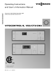
Vitotronic 100, type GC1B or GC4B
VITOTRONIC 100
5592 669 GB
2/2011
Please keep safe.
Safety instructions
For your safety
Please follow these safety instructions closely to prevent accidents and material losses.
Safety instructions explained
Danger
This symbol warns against the
risk of injury.
!
Please note
This symbol warns against the
risk of material losses and environmental pollution.
Note
Details identified by the word "Note" contain additional information.
Target group
These operating instructions are for the
heating system user.
This unit is not designed to be used by
persons (including children) with limited
bodily, sensory or mental capacities, or
lacking experience and/or lacking knowledge, unless they are supervised by a
person responsible for their safety, or
have received instructions from such a
person as to how to use the unit.
Please note
Children should be supervised.
Ensure that children do not play
with the unit.
If you smell gas
Danger
Escaping gas can lead to explosions which may result in serious
injury.
■ Do not smoke. Prevent naked
flames and sparks. Never
switch lights or electrical appliances ON or OFF.
■ Close the gas shut-off valve.
■ Open windows and doors.
■ Remove all people from the
danger zone.
■ Notify your gas or electricity
supplier and your heating contractor from outside the building.
■ Shut off the electricity supply to
the building from a safe place
(outside the building).
5592 669 GB
!
Danger
Incorrectly executed work on the
heating system can lead to lifethreatening accidents.
■ Work on gas appliances must
only be carried out by a registered gas fitter.
■ Work on electrical equipment
must only be carried out by a
qualified electrician.
2
Safety instructions
For your safety (cont.)
If you smell flue gas
Danger
Flue gas can lead to life-threatening poisoning.
■ Shut down the heating system.
■ Ventilate the boiler room.
■ Close all doors in the living
space.
In case of fire
Ancillary components, spare and
wearing parts
!
Please note
Components that are not tested
with the heating system may lead
to damage to the heating system,
or may affect their various functions.
Installation or replacement work
must only be carried out by qualified personnel.
Danger
Fire creates the risk of burning
and explosions.
■ Shut down the heating system.
■ Close the shut-off valves of the
fuel lines.
■ Use a tested fire extinguisher,
class ABC.
Boiler room requirements
5592 669 GB
!
Please note
Incorrect ambient conditions can
lead to damage to the heating
system and put the safe operation at risk.
■ Ensure ambient temperatures
above 0 ºC and below 35 ºC.
■ Prevent air contamination by
halogenated hydrocarbons
(e.g. as contained in paints,
solvents or cleaning fluids) and
excessive dust (e.g. through
grinding/polishing work).
■ Avoid continuously high humidity levels (e.g. through frequent
drying of washing).
■ Never close existing ventilation
apertures.
3
Index
Index
Introductory information
Commissioning.....................................................................................................
Your system is preset at the factory.....................................................................
Special considerations for multi boiler systems....................................................
Terminology..........................................................................................................
6
6
7
7
Operation
Controls................................................................................................................
■ Opening the control unit....................................................................................
■ Programming unit..............................................................................................
How to use the controls........................................................................................
Symbols on the display........................................................................................
8
8
8
9
9
Start-up/shutdown
Starting the heating system..................................................................................
Shutting down the heating system.......................................................................
■ With frost protection monitoring........................................................................
■ Without frost protection monitoring (shutdown)................................................
10
12
12
12
Central heating
Selecting the set boiler water temperature........................................................... 13
Setting the heating program (central heating)...................................................... 13
Stopping the central heating................................................................................. 13
DHW heating
Required settings (DHW heating).........................................................................
Setting the DHW temperature..............................................................................
Setting the heating program (DHW heating)........................................................
Stopping DHW heating.........................................................................................
14
14
14
15
Further adjustments
Setting the temperature unit (°C/°F)..................................................................... 16
Restoring factory settings..................................................................................... 16
Scanning
Scanning information............................................................................................ 17
Scanning the service messages........................................................................... 19
Scanning fault messages..................................................................................... 20
What to do if...
Rooms are too cold.............................................................................................. 22
4
5592 669 GB
Emissions test mode......................................................................................... 21
Index
Index (cont.)
Rooms are too hot................................................................................................
There is no hot water............................................................................................
The DHW is too hot..............................................................................................
"ã" flashes on the display ..................................................................................
"ë" flashes on the display...................................................................................
23
24
24
25
25
Maintenance........................................................................................................ 26
5592 669 GB
Keyword index.................................................................................................... 30
5
Introductory information
Commissioning
The commissioning and matching of the
control unit to local conditions and building characteristics, as well as instructing
the user in the operation of the system,
must be carried out by your heating contractor.
As the user of new combustion equipment, you may be obliged to notify your
local flue gas inspector of the installation
[check local regulations]. Your local flue
gas inspector will also inform you [where
appropriate] about work he may be
required to perform on your combustion
equipment (e.g. regular checks, cleaning).
Your system is preset at the factory
The control unit is factory-set to "
"
for central heating and DHW heating.
Your heating system is therefore ready
for use:
Central heating
■ The rooms are heated in accordance
with the settings on your control unit
and room temperature control unit.
■ Your heating contractor can make further settings for you during commissioning.
You can change any settings individually at any time to suit your requirements (see chapter "Central heating").
Frost protection
■ Your boiler and DHW cylinder are protected against frost.
Power failure
■ All data is saved if there is a power
failure.
5592 669 GB
DHW heating
■ The DHW is heated up to 50 °C.
■ Your heating contractor can make further settings for you during commissioning.
You can change any settings individually at any time to suit your requirements (see chapter "DHW heating").
6
Introductory information
Special considerations for multi boiler systems
The Vitotronic 100 can be used in the
following systems:
■ Single boiler systems
■ Multi boiler systems with a Viessmann
cascade control unit
■ Multi boiler systems of a higher third
party control unit
In multi boiler systems (systems with
several boilers), each boiler is equipped
with its own control unit. These control
units are regulated by the higher control
unit. Make the required settings (e.g. set
room temperature) at the higher control
unit.
DHW heating can only be selected at
the higher control unit.
Operating instructions
of the higher control unit
Note
These operating instructions do not
apply in conjunction with multi boiler systems.
Terminology
5592 669 GB
To provide you with a better understanding of the functions of your control unit,
the appendix contains the chapter "Terminology" (see page 28).
7
Operation
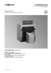
Controls
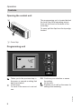
Opening the control unit
The programming unit is located behind
the cover flap. Brief operating instructions can be found on the back of the
cover flap.
To open, pull the flap from the top edge
forward.
A
A Cover flap
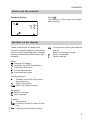
Programming unit
°C
48
s
A
OK Confirms your selection or saves
the setting.
No function.
Enables you to call up the menu for
settings and scanning.
5592 669 GB
Takes you to the previous step in
the menu or cancels a setting that
has been started.
Cursor keys
To scroll in the menu or to set values.
8
Operation
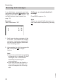
How to use the controls
Press
.
This takes you to the menu for settings
and scanning.
Standard display
°C
48
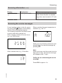
Symbols on the display
These symbols are not always displayed, but appear subject to the system
version and the operating state. Flashing
displays indicate that modifications can
be made.
In conjunction with a solar thermal
system:
Solar circuit pump running
Burner in operation
Factory settings
Menu
Settings for heating
Selecting the DHW temperature
Scanning information
Further adjustments
Emissions test mode
Heating program
Standby mode with frost protection monitoring
DHW heating only
DHW and central heating
5592 669 GB
Messages
Service message
Fault message
Displays
Temperature
Circulation pump at output 20 running
Cylinder primary pump running
9
Start-up/shutdown
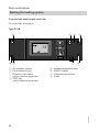
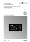
Starting the heating system
Controls with open hinged cover flap
For cover flap, see page 8.
Type GC1B
C
D E
F
°C
48
s
A
BA
E
F
G
H
G
Excess temperature reset
ON/OFF switch
Temperature controller
Fuses
5592 669 GB
A ON indicator (green)
B Fault indicator (red)
C Emissions test switch
(only for service purposes)
D TEST key
(only for service purposes)
H
10
Start-up/shutdown
Starting the heating system (cont.)
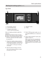
Type GC4B
C
D
°C
48
s
A
BA
E
A ON indicator (green)
B Fault indicator (red)
C Emissions test switch
(only for service purposes)
F ON/OFF switch
H Fuses
Ask your heating contractor about the
following:
■ Boiler and relevant control unit type
■ Level of the required system pressure
■ Position of the pressure gauge, shutoff valves, gas shut-off valve, ventilation apertures
3. Switch ON the power supply, e.g. at
a separate MCB/fuse or a mains isolator.
1. Check the heating system pressure
at the pressure gauge. If the pressure
of the heating system is too low, top
up the water or notify your heating
contractor.
4. Switch ON the ON/OFF switch (see
pages 10 and 11).
After a short time, the standard display appears (see page 9) and the
green ON indicator illuminates. The
heating system is now ready for operation.
5592 669 GB
2. Open the shut-off valves in the oil
lines (at the tank and filter) or open
the gas shut-off valve.
11
Start-up/shutdown
Shutting down the heating system
With frost protection monitoring
Select the heating program " " for
standby mode (frost protection monitoring).
Press the following keys:
1.
for settings; "
5. OK to confirm.
■ No central heating.
■ No DHW heating.
■ Frost protection for the boiler and the
DHW cylinder is enabled.
" flashes.
2. OK to confirm; "
" flashes.
3. OK to confirm; the currently selected heating program flashes.
Note
The circulation pumps are briefly started
every 24 hours to prevent them from
seizing up.
Terminating heating program " "
4.
until " " flashes.
Select another heating program.
Without frost protection monitoring (shutdown)
1. Switch OFF the ON/OFF switch (see
pages 10 and 11).
2. Close the shut-off valves in the oil
lines (at the tank and filter) or close
the gas shut-off valve.
3. Isolate the heating system from its
main power supply, e.g. at a separate
MCB/fuse or a mains isolator.
Information on a prolonged shutdown
Circulation pumps may seize up as they
are not supplied with power.
12
5592 669 GB
4. Where outside temperatures of
below 3 °C are anticipated, please
take suitable measures to protect the
heating system against frost. If necessary, contact your heating contractor.
Central heating
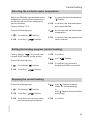
Selecting the set boiler water temperature
Select a sufficiently high set boiler water
temperature (heating flow temperature)
so that the required room temperature
can be achieved.
Factory setting: 75 °C
4. OK to confirm; the selected temperature value flashes.
Press the following keys:
5. /
1.
for settings; "
3.
for set boiler water temperature;
" " flashes.
for the required set boiler water
temperature.
" flashes.
2. OK to confirm; "
" flashes.
6. OK to confirm; the new temperature
value is saved.
Setting the heating program (central heating)
Factory setting: "
" for central heating and DHW heating (winter mode).
3. OK to confirm.
4. /
until "
" flashes.
Press the following keys:
1.
for settings; "
" flashes.
2. OK to confirm; "
5. OK to confirm; the rooms are
heated and DHW is provided.
" flashes.
Stopping the central heating
Press the following keys:
1.
for settings; "
2. OK to confirm; "
4. /
" flashes.
" flashes.
5. OK to confirm.
5592 669 GB
3. OK to confirm; the currently selected heating program flashes.
until " " flashes (summer
mode, no central heating)
or
until " " flashes (frost protection
monitoring).
13
DHW heating
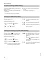
Required settings (DHW heating)
If you want DHW heating, check the following points:
■ Have you set the required DHW temperature?
For settings, see the next chapter.
■ Have you set the correct heating program?
For settings, see page 14.
Setting the DHW temperature
Factory setting: 50 °C
3. OK to confirm; temperature value
flashes.
Press the following keys:
4. /
1.
for settings; "
2.
until " " flashes.
for required DHW temperature.
" flashes.
5. OK to confirm; the new temperature
value is saved.
Setting the heating program (DHW heating)
Factory setting: "
" for central heating and DHW heating (winter mode).
Press the following keys:
1.
for settings; "
2. OK to confirm; "
" flashes.
4. /
until " " flashes for DHW heating (summer mode, no central
heating)
or
until "
" flashes for central
heating and DHW heating (winter mode).
" flashes.
5. OK to confirm; the selected heating
program is activated.
5592 669 GB
3. OK to confirm; the currently selected heating program flashes.
14
DHW heating
Stopping DHW heating
You do not want DHW, but do want to
heat the rooms.
Press the following keys:
1.
for settings; "
5. OK to confirm; DHW heating and
central heating are stopped,
frost protection monitoring is
activated (standby mode).
" flashes.
2. OK to confirm; "
" flashes.
3. OK to confirm; the currently selected heating program flashes.
4. /
until "
" flashes.
5. OK to confirm.
6.
for settings; "
" flashes.
7.
until " " flashes.
8. OK to confirm; temperature value
flashes.
9.
until 10 °C is displayed.
10. OK to confirm; the new temperature value is saved.
You do not want to have DHW or heat
your rooms.
Press the following keys:
1.
for settings; "
" flashes.
2. OK to confirm; "
" flashes.
5592 669 GB
3. OK to confirm; the currently selected heating program flashes.
4.
until " " flashes.
15
Further adjustments
Setting the temperature unit (°C/°F)
Factory setting: °C
3. OK to confirm; " " flashes.
Press the following keys:
4. /
1.
for settings; "
2.
until " " flashes.
for required temperature unit
("°C" or "°F").
" flashes.
5. OK to confirm; the new temperature
unit is saved.
Restoring factory settings
You can simultaneously reset all
changed values to the factory settings.
Press the following keys:
1.
for settings; "
" flashes.
2.
until " " flashes.
3. OK to confirm; " " flashes.
4. OK to confirm; the factory setting is
reinstated.
5592 669 GB
Factory settings:
■ Heating program: "
"
■ Temperature unit: °C
■ Set boiler water temperature: 75 °C
■ Set DHW temperature: 50 °C
16
Scanning
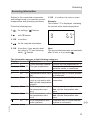
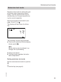
Scanning information
Subject to the connected components
and settings made, you can scan current
temperatures and operating conditions.
Press the following keys:
1.
for settings; "
2.
until " " flashes.
6. OK to confirm; the value is reset.
Example:
The number "3" is displayed, indicating
the current boiler water temperature.
¸
" flashes.
3
°C
65
3. OK to confirm.
4. /
for the required information.
5. OK to confirm; if you want to reset
the value to "0" (see following
table), " " flashes.
Note
The scan mode terminates automatically
after 30 min or if you press .
5592 669 GB
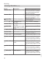
The information appears in the following sequence:
Display
Explanation
Notes
0
1
LON subscriber number Control unit has subscriber no. 1.
2
107 °C Flue gas temperature
Displayed only if a flue gas temperature sensor is connected.
3
65
°C Boiler water temperature —
4
58
°C Temperature buffer cylin- Displayed only if a buffer cylinder
der
is connected.
5
50
°C DHW temperature
Displayed only if a DHW cylinder is
(only in conjunction with connected.
one cylinder temperature
sensor)
51
45
°C DHW temperature, cylin- Displayed only in conjunction with
der temperature sentwo cylinder temperature sensor 1
sors.
52
45
°C DHW temperature, cylin- Displayed only in conjunction with
der temperature sentwo cylinder temperature sensor 2
sors.
5
45
°C DHW temperature with
Displayed only if a solar thermal
solar operation
system is connected.
17
Scanning
Scanning information (cont.)
50
Explanation
°C Temperature sensor /
54
50
°C Temperature sensor aÖ
5
70
°C Collector temperature
6
55
°C Temperature sensor aJA
7
55
°C Temperature sensor aJB
2 6 3 5 7 2 h Hours run burner single
stage, stage 1 or modu1
lating
2 6 3 5 7 2 h Hours run burner stage 2
2
0 1 3.5 7 8
Burner starts
3
001225
Fuel consumption
4
0 0 1 4 1 7 h Solar circuit pump hours
run
5
001425
Pump starts, solar circuit
pump
6
000506
h
Hours run, output 22
7
000506
8
18
Starts output 22
Notes
Displayed only if the Viessmann
solar control module is available
and a third temperature sensor
has been connected.
Displayed only if the Viessmann
solar control module is available
and a fourth temperature sensor
has been connected.
Display only if a solar thermal system is connected.
Only if a sensor is connected.
Only if a sensor is connected.
The value can be reset to "0" with
"D".
The value can be reset to "0" with
"D".
The number of burner starts can
be reset to "0" with "D".
The value can be reset to "0" with
"D".
Displayed only if a Viessmann
solar control module is installed.
The value can be reset to "0" with
"D".
Displayed only if a Viessmann
solar control module is installed.
The value can be reset to "0" with
"D".
Displayed only if a Viessmann
solar control module is installed.
The value can be reset to "0" with
"D".
Displayed only if a Viessmann
solar control module is installed.
The value can be reset to "0" with
"D".
5592 669 GB
Display
53
Scanning
Scanning information (cont.)
Display
002850
9
Explanation
Solar yield in kWh
Notes
Displayed only if a Viessmann
solar control module is installed.
The value can be reset to "0" with
"D".
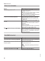
Scanning the service messages
If your heating system is due for a service, the symbol flashes on the display,
and the following displays appear.
Your heating contractor can select when
a service should be carried out:
After a certain number of burner hours
run, e.g. 2500 hours.
When a certain flue gas temperature is
reached, e.g. 150 °C.
a
150
°C
ë
2500
h
After a certain time, e.g. 12 months.
ë
u
12
Notify your local heating contractor and
acknowledge the service message by
pressing OK.
Note
If the service can only be carried out at a
later point in time, the service message
will reappear after 7 days.
Calling up an acknowledged service
message
5592 669 GB
Press OK for approx. 4 s.
19
Scanning
Scanning fault messages
If any faults have occurred in your heating system, the symbol flashes on the
display and the fault code is shown. The
red fault indicator also flashes (see
page 10).
Calling up an acknowledged fault
message
Press OK for approx. 4 s.
Note
If there are several fault messages, you
can scan these in sequence by pressing
/ .
Example:
Fault code shown: "50"
ã
1
50
1. Notify your heating contractor of the
fault code. This enables the heating
contractor to be better prepared for
the service call and may save additional travelling costs.
2. Acknowledge the fault message with
OK. The symbol no longer
flashes.
5592 669 GB
Note
■ If you have connected up signalling
equipment (e.g. a buzzer) for fault
messages, this is deactivated
when the fault message is
acknowledged.
■ If the fault can only be fixed at a
later point in time, the fault message will reappear the following
day.
20
Emissions test mode
Emissions test mode
Emissions test mode for testing flue gas
with boiler water temperature raised
briefly. This test mode should only be
activated by your flue gas inspector during the annual inspection.
Switch the emissions test switch (see
page 10 and 11) to .
The display will then show the following:
°C
48
The following functions are activated:
■ The burner is switched ON (the display
shows symbol ).
Note
Burner start-up can be delayed, e.g.
through fuel oil preheating.
■ Pumps are started.
■ The thermostat regulates the boiler
water temperature.
Ending emissions test mode
5592 669 GB
Set the emissions test switch to position
a
or
Close the flap (see page 8).
21
What to do if...
Rooms are too cold
Cause
The heating system is off.
Control unit incorrectly adjusted.
Only when operating with DHW heating:
DHW priority is enabled ("
" is displayed).
No fuel.
symbol is shown on the display.
For LPG/oil:
Check the fuel reserves and re-order if
required.
With natural gas:
Open the gas shut-off valve. If necessary,
check with your gas supply utility.
Scan the type of fault, make a note of the
fault code and acknowledge the message
(see page 20). If necessary, notify your
heating contractor.
5592 669 GB
The
Remedy
■ Switch ON the ON/OFF switch (see
pages 10 and 11).
■ Switch ON the mains isolator, if installed (outside the boiler room).
■ Reset the MCB in the power distribution
board (main domestic MCB).
Check settings and correct if required:
■"
" must be selected (see page 13).
■ Set boiler water temperature (see
page 13).
Wait until the DHW cylinder has been
heated up.
22
What to do if...
Rooms are too cold (cont.)
Cause
Burner start faulty.
The symbol is displayed and the red
fault indicator on the burner is illuminated.
Vitoair draught stabiliser faulty.
Remedy
Press the reset button on the burner hood
or on the boiler front panel. If there is no
reset button, switch the ON/OFF switch
(see pages 10 and 11) first OFF and then
ON again.
Contact your local heating contractor if
the burner still fails to start.
Contact your local heating contractor.
Press the rotary selector on the motor and
rotate it past this position A as far as it
will go.
A
Rooms are too hot
Cause
Control unit is incorrectly adjusted.
The
symbol is shown on the display.
.
5592 669 GB
Emissions test switch is set to
Remedy
Check settings and correct if required:
■ Set boiler water temperature (see
page 13).
Scan the type of fault, make a note of the
fault code and acknowledge the message
(see page 20). If necessary, notify your
heating contractor.
Close the flap (see page 8).
23
What to do if...
There is no hot water
Cause
The heating system is off.
Control unit incorrectly adjusted.
No fuel.
The
symbol is shown on the display.
Remedy
■ Switch ON the ON/OFF switch (see
pages 10 and 11).
■ Switch ON the mains isolator, if installed (outside the boiler room).
■ Reset the MCB in the power distribution
board (main domestic MCB).
Check settings and correct if required:
■ DHW heating must be enabled (see
page 14).
■ Set DHW temperature (see page 14).
For LPG/oil:
Check the fuel reserves and re-order if
required.
With natural gas:
Open the gas shut-off valve. If necessary,
check with your gas supply utility.
Scan the type of fault, make a note of the
fault code and acknowledge the message
(see page 20). If necessary, notify your
heating contractor.
The DHW is too hot
Cause
The control unit is incorrectly adjusted.
DHW heating is carried out by the solar
thermal system.
Remedy
Check and correct the DHW temperature
if required (see page 14).
Check and correct settings, if required, at
the solar control unit.
Separate operating instructions
.
Close the flap (see page 8).
5592 669 GB
Emissions test switch is set to
24
What to do if...
"ã" flashes on the display
Cause
Heating system fault.
Remedy
Scan the type of fault, make a note of the
fault code and acknowledge the message
(see page 20). If necessary, notify your
heating contractor.
"ë" flashes on the display
Remedy
Notify your local heating contractor and
acknowledge the service message with
OK (see page 19).
5592 669 GB
Cause
The time for a service, as specified by
your heating contractor, has arrived.
25
Maintenance
Maintenance
Cleaning
All equipment can be cleaned with a
commercially available domestic cleaning agent (non-scouring). Clean the surface of the programming unit with a
microfibre cloth.
Inspection and maintenance
Inspection and maintenance of your
heating system is prescribed by the
Energy Savings Order and DIN 4755,
DVGW-TRGI 2008 and DIN 1988-8.
Regular maintenance ensures troublefree, energy efficient, environmentally
responsible and safe heating. Your heating system must be serviced by an
authorised contractor at least every
2 years. For this, we advise you to
arrange an inspection and maintenance
contract with your local heating contractor.
Refill any water treatment equipment
(e.g. a lock or injection system) in good
time, if such equipment is installed in the
cold water supply of the DHW cylinder.
Observe the manufacturer's instructions.
Additionally for a Vitocell 100:
We recommend that the correct function
of the sacrificial anode is checked annually by your heating contractor.
The anode function can be checked without interrupting the system operation.
The heating contractor will check the
earth current with an anode tester.
Boiler
Safety valve (DHW cylinder)
DHW cylinder (if installed)
The DIN 1988-8 and EN 806 specify that
maintenance and cleaning should be
carried out no later than two years after
commissioning and thereafter as
required.
Only a qualified heating contractor
should clean the inside of a DHW cylinder and the DHW connections.
26
The safety valve function should be
checked every six months by venting,
either by the system user or the local
heating contractor. The valve seat may
become contaminated (see the valve
manufacturer's instructions).
5592 669 GB
Increasing boiler contamination raises
the flue gas temperature and thereby
increases energy losses. For that reason, all boilers should be cleaned annually.
Maintenance
Maintenance (cont.)
Potable water filter (if installed)
5592 669 GB
To maintain high hygienic standards,
proceed as follows:
■ Replace filter element on non-back
flushing filters every six months (visual
inspection every two months).
■ On back flushing filters, back flush
every two months.
27
Terminology
Constant temperature operation
Heating circuit
In constant temperature operation, the
heating water is constantly heated to the
selected boiler water temperature.
A heating circuit is a sealed circuit
between the boiler and radiators, in
which the heating water circulates.
Heating program
Heating circuit pump
The heating program determines
whether you heat your rooms and DHW,
or only heat DHW, or whether you shut
down your heating system with frost protection monitoring.
Circulation pump for the circulation of the
heating water in the heating circuit.
Note
A heating program for central heating
without DHW heating is not available. If
rooms are to be heated, hot water is generally also required (winter mode).
If you still only want central heating,
select the "
" heating program and
set the DHW temperature to 10 °C (see
page 15). This means that you will not
heat DHW unnecessarily but the DHW
cylinder is protected against frost.
Current temperature at the time of the
scan; e.g. actual DHW temperature.
Boiler water temperature
See "Constant temperature operation".
Open flue operation
The combustion air is drawn from the
room where the boiler is installed.
Balanced flue operation
The combustion air is drawn from outside the building.
Safety valve
A safety device that must be installed by
your heating contractor in the cold water
pipe. The safety valve opens automatically to prevent excess pressure in the
DHW cylinder.
Set temperature
Default temperature that should be
reached; e.g. set DHW temperature.
28
5592 669 GB
You can select the following heating programs:
■"
"
The rooms are heated and DHW is
provided (winter mode).
■" "
DHW is provided but there is no central heating (summer mode).
■" "
Frost protection for the boiler and
DHW cylinder is active, no central
heating, no DHW heating (standby
mode).
Actual temperature
Terminology (cont.)
Summer mode
Heating program " ".
At warmer times of the year, i.e. when
the rooms do not have to be heated, you
can stop heating mode. The boiler
remains enabled for DHW heating.
Cylinder primary pump
Circulation pump for heating the DHW in
the DHW cylinder.
Drinking water filter
5592 669 GB
A device that removes solids from the
water. The drinking water filter is installed in the cold water pipe upstream of the
DHW cylinder or the instantaneous
water heater.
29
Keyword index
Keyword index
A
Actual temperature.............................28
Frost protection....................................6
Frost protection monitoring....12, 13, 15
B
Balanced flue operation.....................28
Boiler water temperature....................28
H
Heating and DHW................................6
Heating circuit....................................28
Heating circuit pump..........................28
Heating mode
■ Setting............................................13
■ Without DHW heating.....................15
Heating only.......................................15
Heating operation
■ Constant temperature.....................28
Heating program
28, 29
■ DHW heating..................................14
■ For central heating..........................13
Heating system
■ Starting...........................................11
■ Stopping.........................................12
Hot rooms..........................................23
How to use the controls.......................9
D
DHW heating........................................6
■ Factory setting..................................6
■ Heating program.............................14
■ Required settings............................14
■ Setting the DHW temperature........14
■ Stopping.........................................15
Display elements
■ Type GC1B.....................................10
■ Type GC4B.....................................11
Drinking water filter............................29
E
Emissions test mode..........................21
F
Factory setting.....................................6
Fault message
■ Acknowledging...............................20
■ Calling up (acknowledged).............20
■ Scanning.........................................20
Filter...................................................29
30
I
Inspection...........................................26
K
Keys.....................................................8
M
Maintenance......................................26
Maintenance contract.........................26
Menu....................................................9
Multi boiler systems.............................7
N
No hot water.......................................24
Notice of completion............................6
O
Open flue operation...........................28
Operation.............................................8
■ Controls............................................8
■ How to use the controls....................9
5592 669 GB
C
Central heating
■ Factory setting..................................6
■ Heating program.............................13
■ Stopping.........................................13
Cleaning.............................................26
Cleaning information..........................26
Commissioning..............................6, 11
Constant temperature operation........28
Controls................................................8
■ Type GC1B.....................................10
■ Type GC4B.....................................11
Cylinder primary pump.......................29
Keyword index
Keyword index (cont.)
P
Power failure........................................6
Pressure gauge..................................11
Programming unit.................................8
Pump
■ Cylinder..........................................29
■ Heating circuit.................................28
R
Reset..................................................16
Resetting data....................................17
Resetting fuel consumption................17
Resetting hours run............................17
Restoring factory settings..................16
Rooms too cold..................................22
Rooms too hot....................................23
Room temperature control unit............8
T
Temperature
■ Actual temperature.........................28
■ Boiler water.....................................28
■ DHW...............................................14
■ Scanning.........................................17
■ Set temperature..............................28
Temperature unit................................16
Terminology.......................................28
Test mode..........................................21
Troubleshooting.................................22
W
Water too cold....................................24
Water too hot.....................................24
Where to find the controls....................8
Winter mode.......................................28
5592 669 GB
S
Safety valve.......................................28
Scan
■ Fault message................................20
■ Information......................................17
■ Operating conditions.......................17
■ Service message............................19
■ Temperatures.................................17
Scanning information.........................17
Scanning operating conditions...........17
Scanning the actual temperature.......17
Selecting the set boiler water temperature.....................................................13
Service message
■ Acknowledging...............................19
■ Calling up (acknowledged).............19
■ Scanning.........................................19
Set temperature.................................28
Shutdown...........................................12
Shutting down
■ Heating system without frost protection monitoring................................12
Standard display..................................9
Standard settings...............................16
Standby mode..................12, 13, 15, 28
Starting
■ Frost protection monitoring.............12
■ Heating system...............................10
■ Standby mode................................12
Starting the appliance........................11
Stopping
■ Central heating...............................13
■ DHW heating..................................15
■ Heating system with frost protection
monitoring.......................................12
Summer mode.......................13, 28, 29
Symbols on the display........................9
31
Your contact
Contact your local contractor if you have any questions regarding the maintenance
and repair of your system. You may, for example, find local contractors on the internet
under www.viessmann.com.
Viessmann Werke GmbH&Co KG
D-35107 Allendorf
Telephone: +49 6452 70-0
Fax: +49 6452 70-2780
www.viessmann.com
32
Viessmann Limited
Hortonwood 30, Telford
Shropshire, TF1 7YP, GB
Telephone: +44 1952 675000
Fax: +44 1952 675040
E-mail: [email protected]
chlorine-free bleached paper
Printed on environmentally friendly,
7441811
5592 669 GB
Serial No.:
7441810
Subject to technical modifications.
Applicability