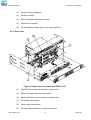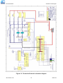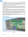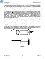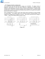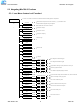
1
Installation & Operation Manual RT9 Powershelf Document: 158-1806-01.doc Date: 21 December 2005 © Rectifier Technologies Pacific Pty Ltd ACN 058 107 707 Wave Communications Pty Ltd Unit 5, 97 Jijaws St Sumner Park QLD 4074 TEL: 07 3279 0600 FAX: 07 3279 0544 EMAIL: [email protected] WEBSITE: www.wavecomeng.com.au RT9 Powershelf Rectifier Technologies Table of Contents 1. General Warnings ...............................................................................4 2. Configuration ..............................................................................................................5 2.1 General Description ...............................................................................................5 2.2 3. 4. System Description ................................................................................................5 2.2.1 Front View ......................................................................................................5 2.2.2 Rear View .......................................................................................................6 Installation ..................................................................................................................8 3.1 Mounting the Powershelf .......................................................................................8 3.1.1 Tools Required for Installation ........................................................................8 3.1.2 Gaining Access to Rear Wiring.......................................................................9 3.2 Overview of External Wiring Connections..............................................................9 3.3 Mains Connections ..............................................................................................11 3.3.1 Factory Supplied Configurations...................................................................12 3.3.2 Single phase – individual protected external feeds.......................................12 3.3.3 3 phase star – individual protected external feeds........................................13 3.3.4 3 phase delta – individual protected external feeds......................................13 3.3.5 Surge protection requirements .....................................................................14 3.4 Bulk Load connections.........................................................................................15 3.5 Load Distribution CB Trip Sense connections......................................................15 3.6 Battery connections .............................................................................................16 3.7 Temperature Sensors ..........................................................................................17 3.8 Auxiliary relay connections ..................................................................................17 3.9 MiniCSU-3 Power Connections ...........................................................................18 3.10 Front Panel USB Communications connection ................................................18 3.11 Remote Communication connection.................................................................18 3.11.1 Isolated RS232 Interface ..............................................................................19 3.11.2 Isolated RS485 Interface ..............................................................................19 3.11.3 Optical Plastic Fibre Interface.......................................................................19 3.11.4 TCP/IP and WebCSU Interfaces...................................................................20 3.11.5 Embedded Modems......................................................................................20 3.12 Battery/Load Distribution Module .....................................................................21 3.13 Adding Auxiliary Expansion Modules ...............................................................22 Commissioning.........................................................................................................23 158-1806-01.doc 2 2-Mar-06 RT9 Powershelf 5. Operation ..................................................................................................................24 Summary of MiniCSU-3 front panel controls .................................................................24 5.1 Alpha-numeric Display..................................................................................25 5.1.2 Front Panel Pushbuttons ..............................................................................25 5.1.3 Status Indicating LEDs (MiniCSU-3).............................................................25 Password security.........................................................................................26 5.2.2 When an alarm condition exists ....................................................................26 5.2.3 MiniCSU-3 Alarms ........................................................................................27 5.2.4 User programmable relay functions ..............................................................28 Navigating MiniCSU-3 Functions .........................................................................29 5.3.1 Base Menu (System Level Functions) ..........................................................29 5.3.2 SMR Menu (Rectifier Specific Functions) .....................................................32 5.3.3 Alarm Log .....................................................................................................32 5.3.4 Battery Menu (Battery Specific Functions)....................................................33 Troubleshooting .......................................................................................................35 6.1 To Remove a Rectifier Module or a MiniCSU-3 Controller...................................37 6.2 To Insert a Rectifier Module or a MiniCSU-3 Controller.......................................37 Appendix A – Setting Up Network Interfaces.........................................................38 7.1 Programming IP addresses using DeviceInstaller software. ................................38 7.1.1 Preparations for local address set up ...........................................................38 7.1.2 Local IP address set up procedure ...............................................................38 7.1.3 Preparations for gateway address set up .....................................................39 7.1.4 Gateway IP address set up procedure..........................................................39 7.2 8. MiniCSU-3 Security & Alarms ..............................................................................26 5.2.1 5.3 7. MiniCSU-3 Components ......................................................................................25 5.1.1 5.2 6. Rectifier Technologies Programming IP addresses using ARP and Telnet access..................................40 7.2.1 Preparations for local address set up ...........................................................40 7.2.2 Local IP address set up procedure ...............................................................40 7.2.3 Configuring the Unit ......................................................................................41 7.2.4 Server Configuration (Network Configuration) ..............................................42 Specifications ...........................................................................................................44 158-1806-01.doc 3 2-Mar-06 RT9 Powershelf Rectifier Technologies 1. General Warnings 1. This equipment has been designed to be used only in restricted access areas. 2. This equipment must only be serviced by authorised and qualified service personnel. 3. Operators should not attempt to repair faulty units. There are no operator serviceable parts inside. All fuses are only replaced as part of a repair procedure in a repair facility by authorised personnel and not as a maintenance procedure on site. 4. The powershelf magazine should be mounted in a rack that satisfies the requirements for electrical enclosures and fire enclosures according to IEC60950 or equivalent standard. For open rack use, the back of the magazine must be fully enclosed by its covers and the AC wiring terminations must be protected by either an earthed casing or an enclosure that provides double insulation. 5. The powershelves must be used with sufficient ventilation. After mounting, the air flow paths into and out of the rectifiers must be unrestricted. Allow adequate flow for exhaust air out of the rack. 6. Rectifiers are live at all times when the rectifier is plugged into the backplane connector. The input AC disconnection device is the rectifier backplane connector. 7. When removing modules, especially if the ambient temperature is high and the unit has been operating at maximum load, avoid skin contact with the metal casing as it may be too hot to touch. Pull the unit halfway out of the magazine and let cool for 2-3 minutes before handling. 158-1806-01.doc 4 2-Mar-06 RT9 Powershelf Rectifier Technologies 2. Configuration 2.1 General Description RT9 Powershelf systems are turn-key DC uninterruptible power supply solutions (DC UPS) for powering 24VDC or 48VDC telecommunications and industrial equipment. The Powershelf provides integrated battery management functions for a range of battery types (VRLA, flooded Lead-acid, NiCd, Ni-MH, Li-polymer) to enable easy commissioning of a DC UPS or it can be used as a standalone DC source when no batteries are used. The Powershelf provides the following integrated features: • battery (& load) distribution • battery & load circuit breaker trip sensing • battery charge current limiting • short circuit and reverse polarity protection • battery temperature sensing • n+1 redundant rectifiers • low voltage disconnection • a monitoring and control module (MiniCSU-3) • automated/remote battery discharge testing • super capacitor backed real-time system clock • accurate temperature compensated Float and Equalisation voltages • optional remote communication including web-based protocols • optional modules for monitoring AC power and battery cell voltages • all rectifiers and the controller are hot-swap and plug-and-play capable • optional AC distribution capability, 2.2 System Description 2.2.1 Front View 4 1 3 2 5 Figure 2.1 System blocks (PSLF-1110) 3 4 2 1 Figure 2.2 System blocks (PSLF-1115) 158-1806-01.doc 5 2-Mar-06 RT9 Powershelf Rectifier Technologies (1) Rack mounting magazine (2) Rectifier module (3) Battery (& load) distribution module (4) MiniCSU-3 controller (5) AC distribution module (option on some systems) 2.2.2 Rear View Figure 2.3 Rear view of connections (PSLF-1115) (1) MiniCSU-3 backplane & interface connections (2) Battery (& load) switched connections (3) Battery (& load) common return connection bar (4) AC mains terminations (5) Alarm relay connections (6) Remote communications module connection 158-1806-01.doc 6 2-Mar-06 RT9 Powershelf 1 Rectifier Technologies 2 3 4 5 6 7 8 Figure 2.4 Connections on MiniCSU-3 backplane (1) Remote communications module connection (14-way ribbon) (2) Auxiliary peripheral module (relays, battery cell monitor, etc) connection (16-way ribbon)* (3) Battery (& load) distribution module connection** (34-way ribbon) (4) Ambient temperature sensor connection (sensor P/N 804-1100-01) (5) Battery temperature sensor connection (sensor P/N 804-1100-01) (6) Rectifier isolated communications connection (10-way ribbon)* (7) Standalone system voltage connection (MiniCSU-3 power and voltage sensing) – special use only (8) Load circuit breaker trip detection circuitry connection Notes: * Devices and cable connections are pre-wired as part of the supplied and tested Powershelf ** This connection can be left unused if the system has no requirement for control and maintenance of batteries (ie standalone DC power supply) Figure 2.5 Alarm relay board connections. The alarm relay board is inverted when installed in the Powershelf lid such that Relay 5 is on the left when viewed from the rear of the metalwork. The connections are labelled again on the rear cover. Each alarm is user programmable through the MiniCSU-3 using the WinCSU-2 PC software. 158-1806-01.doc 7 2-Mar-06 RT9 Powershelf Rectifier Technologies 3. Installation 3.1 Mounting the Powershelf The Powershelf is mounted into a standard 19” rack using M5 or M6 screws and cage nuts. For systems larger than 4U (rack units) in height, multiple standard Powershelf magazines are strapped together by four of 18x63mm strapping plates – two at the rear that must remain in place, and two on the front that can be removed once the shelf is secured in the rack. A minimum of 4 screws are required to secure the Powershelf into the rack. It is recommended to initially install the Powershelf into the rack without either the MiniCSU-3 or the RT9 rectifiers in place. M5 or M6 mounting screws Figure 3.1 Mount points for securing Powershelf in a rack Wiring for the standard Powershelf is rear access only. For systems where rear access is not available, the Powershelf can be pre-wired for load, battery, AC power and remote communications before mounting the magazine in the rack. For maintenance and load expansion, the Powershelf is slid forward until the rear top cover is able to be opened to access the wiring points with suitably insulated tools. 3.1.1 Tools Required for Installation • No. 2 Posi-drive screwdriver (for tightening rack bolts) • No. 1 Posi-drive screwdriver • 10mm open-ended spanner or socket (insulated for live DC work) • 4mm Hex-bar driver (insulated for live DC work) • 5mm flat-blade screwdriver (for tightening DIN rail terminal screws) 158-1806-01.doc 8 2-Mar-06 RT9 Powershelf Rectifier Technologies 3.1.2 Gaining Access to Rear Wiring NOTE: Access to the rear wiring should be limited to qualified service personnel. It is recommended to remove the AC power before gaining access to the rear wiring due to the safety hazard present inside the electrical enclosure. Similarly, the energy hazard associated with the batteries connected to the DC bus must be addressed through the use of appropriately insulated tools and other measures to prevent accidental short circuits to the DC bus. Figure 3.2 Opening top rear cover to access wiring To open the top rear cover, remove the two rear M3 screws securing the cover to the back. The top cover will then hinge up to provide access to the wiring. To gain further access to the wiring, remove the rear cover grills by removing the two screws holding each 1U grill. 3.2 Overview of External Wiring Connections Figure 3.3 shows the internal and interface schematic for the PSLF-1115. For the purpose of indicating how a system is connected, the same schematic applies to other Powershelf products. The system shown is for a –48V system where the positive side of the DC bus is tied to earth, usually on the common return bar. For +24V systems, the opposite is usually the case with the negative DC bus being connected to the common return bar that is in turn earthed. It is also possible to float the output, but under these conditions, there is no guarantee that all voltages on the DC bus will stay below the Safety Extra-Low Voltage (SELV) limits with respect to earth during fault conditions. 158-1806-01.doc 9 2-Mar-06 RT9 Powershelf Rectifier Technologies Figure 3.3 Powershelf internal schematic diagram 158-1806-01.doc 10 2-Mar-06 RT9 Powershelf Rectifier Technologies The switched battery cables (-ve in a –48V system) terminate on the copper bars of the battery distribution module (item 2 in Figure 2.3), while the battery return cables terminate on the common return bar (item 3 in Figure 2.3). The battery distribution module can be configured for up to four battery strings with the appropriate number of return cable termination points being available on the common bar. Load switched connections can be made either through the optional load circuits that can be installed in the battery distribution module, or as bulk load connections to the main rectifier busbars. The load return is then terminated either on the common return bar or on the rectifier common busbars. External DC distribution feed connections are made as a bulk load connection. In many cases, the AC distribution is external to the Powershelf. The AC feed should be wired as individually protected feeds for each rectifier (recommended and preferred) to provide discrimination of fault protection devices. Alternatively, a single AC supply (1φ or 3φ) can be used, but there will not be any discrimination and if one unit generates a fault, the power to all rectifiers will be removed. Where the AC distribution is integrated into the Powershelf, each rectifier feed is individually protected and the installer is only required to connect a single AC supply (1φ or 3φ) to the AC DIN rail terminations. Remote communications and alarm relay cabling connects to the top rear cover. Allow enough free cable to permit the top cover to hinge open or to remove the Powershelf from the front of the rack for maintenance. 3.3 Mains Connections Figure 3.4 158-1806-01.doc 11 2-Mar-06 RT9 Powershelf Rectifier Technologies 3.3.1 Factory Supplied Configurations Powershelves without internal AC distribution (eg. PSLF-1115), unless specially ordered, are configured with each rectifier active line being terminated in an individual DIN rail terminal block (beige) and the remaining AC line is connected to a common neutral bar (blue terminal blocks). The system is shipped with a shorting link installed that connects all the active terminals together, thereby making the system a single supply, single phase load. For Powershelves with AC distribution (eg. PSLF-1110), unless specially ordered, the AC active feeds to the circuit breakers are connected to one of three terminal blocks (beige). The unswitched AC lines to the rectifiers are tied together on a common neutral bar (blue blocks). The wiring is arranged this way to allow the system to be configured easily for single phase or three phase “star-connection” supply. The system is shipped with a shorting link joining the three active terminations, thereby making the system a single supply, single phase load by default. The shorting link/s must be removed before connecting a 3 phase supply. The label over the AC terminations indicates the L1, L2, L3 (equivalent to R, S, T phases), N, PE connections to indicate how the Powershelf with AC distribution is wired. AC feed wiring should be sized appropriately for the number of rectifiers being powered (allow for 10A per unit as maximum AC load). 3.3.2 Single phase – individual protected external feeds Connect each of the circuit breaker protected active wires to the individual terminal blocks that feed each rectifier. Remove the shorting link from the active terminal blocks (“A” block). Connect the neutral wire/s to the common neutral terminals. Figure 3.5 158-1806-01.doc 12 2-Mar-06 RT9 Powershelf Rectifier Technologies 3.3.3 3 phase star – individual protected external feeds Remove the link connecting the active terminals “A” together. Connect one phase wire per “A” terminal. Connect the neutral wires to the common neutral terminals. Figure 3.6 3.3.4 3 phase delta – individual protected external feeds Phase-to-phase (208VAC) connections require that the AC terminal blocks for the neutral be replaced with individual active line terminals. Then for each rectifier, the two AC lines can be wired to the appropriate phases. This configuration needs to be specially ordered to ensure that the correct number of terminal blocks is loaded. The system will be shipped with links in the active terminal blocks to configure the system as single phase (but for phase-to-phase connection). Note that double fused versions of RT9 must be ordered. To wire as 3 phase delta, remove the links connecting the active terminals together, and connect each phase-to-phase pair of wires to a set of “A” and “C” terminals. Phase rotation is not important. Double pole circuit breakers are required. Figure 3.7 158-1806-01.doc 13 2-Mar-06 RT9 Powershelf Rectifier Technologies 3.3.5 Surge protection requirements The rectifiers are internally protected for surges up to 6kV/3kA. For higher levels of protection, particularly for sites with high incidence of lightning or switching surges, additional surge protection is required on the AC feed to the Powershelf. Typically surge arrestors with a 10kA-40kA rating are required with the highest level of protection being provided when arrestors are connected between phase-netural (x3 phases) and between phase/neutral-earth (x 3 phases). Other arrangements (for 3-phase “star”) with similar levels of protection are also possible as shown below. The voltage rating of the arrestor should be selected based on the maximum AC voltage likely to appear on the line. The arrestor should limit the voltage to <1200V – 1400V at the rated maximum pulse current. Figure 3.8 158-1806-01.doc 14 2-Mar-06 RT9 Powershelf Rectifier Technologies 3.4 Bulk Load connections Figure 3.9 A bulk load can either be a single large load, or a cable connection to an additional, external DC distribution unit. There are two M6 studs available for securing either 2 cables with single-hole lugs or a cable with double-hole lugs. Single hole lugged cables will require additional cable tying to prevent the cable from rotating on the studs. The positive and negative bars are always in the same position, irrespective of whether the system is –48VDC or +24VDC. In the case of the +24V system, the common return bar is connected to the –VE busbar. 3.5 Load Distribution CB Trip Sense connections To enable monitoring and alarming of tripped external load distribution circuit breakers, a 3-terminal connector is provided on the MiniCSU-3 backplane - item (8) in Figure 2.4. The signal is ACTIVE HIGH for any circuit breaker going open circuit. Below is an example of how to configure external auxiliary contacts to interface to the line. +15V and 0V is available on the connector to power active circuits if required. Note: the connection can be used in parallel with load circuits in the battery/load distribution unit. 158-1806-01.doc 15 2-Mar-06 RT9 Powershelf Rectifier Technologies Figure 3.10 3.6 Battery connections Figure 3.11 For –48VDC systems, the battery negative cables are terminated on the switched line terminals of the battery distribution module (shown above), while the battery positive cables are all tied to the common return bar. The cables can be either brought out through the cut out adjacent to the return bar, or through the break-out slot in the top cover. For +24VDC systems, the battery positive cables are terminated to the battery distribution module, and the negative cables are tied to the common return bar. The internal wiring of the +24VDC systems is different to that shown in the figure only in the swapping of the polarity of the live and common DC lines. In standard Powershelf systems, not all of the 4 possible battery connection strings are installed. The figure shows a battery distribution unit fitted with all the optional battery strings possible. See BDM section below for details about adding extra battery strings or load distribution lines to the BDM. The M4 terminations at one end of the common return bar are available for connection of the “central office earth” – the single point connection where the DC system is tied to the building earthing system. This cable must be sized accordingly to carry the battery short circuit current for the time required to clear the battery protection devices. Note: Ensure the battery circuit breakers are open before connecting the batteries. Connect the switched cable connections first, followed by the common return cable connections. 158-1806-01.doc 16 2-Mar-06 RT9 Powershelf Rectifier Technologies 3.7 Temperature Sensors The optional sensors for measuring ambient and battery temperature are the same device (Part No. 804-1100-01). The system auto-detects if the sensor is plugged into one of the positions (4) or (5) shown in Figure 2.4. If no sensor is installed, the MiniCSU-3 will show “Not Available” in the menu items for the temperature measurements. Locate the ambient sensor close to the intake air zone of the Powershelf. Locate the battery sensor on a battery block in the middle shelf of the battery bank (likely hot zone). 3.8 Auxiliary relay connections Figure 3.12 Alarm relay connections (right) and remote communications module location (left) The user configurable auxiliary relays contacts are shown above. The contacts are rated for 1A 250VAC or 1A 32VDC and have >1kV isolation to the coils. The pin configuration is: (Pin 1 at the right in Figure 3.12) Relay # Pin # Pin function 1 1 N.O. (normally open) 2 N.C. (normally closed) 3 C (common) 4 N.O. 5 N.C. 6 C 7 N.O. 8 N.C. 9 C 2 3 4 5 10 N.O. 11 N.C. 12 C 13 N.O. 14 N.C. 15 C 158-1806-01.doc The relays, being user configurable, can be arranged to activate for multiple alarm conditions or a single alarm only. The logic can be inverted for individual relays so that one becomes a controller failure indicator (use the normally closed contact as this will also indicate if the relay power has failed). 17 2-Mar-06 RT9 Powershelf Rectifier Technologies 3.9 MiniCSU-3 Power Connections Power for the MiniCSU-3 and its peripherals is derived from the DC bus or the highest charged battery. The Battery distribution module has reverse polarity protection circuit that also serves to provide an “or-ing” of the highest supply voltage for the MiniCSU-3. There is one common connection to the +VE bus (in the case of a –48V system) and one connection each to the battery –VE bar on the LVDS and the –VE DC bus connection. The system voltage is sensed and controlled solely on the connections to the DC bus (-VE is sensed where it connects to the LVDS and the +VE is sensed on the common return bar). This is considered close enough to the batteries to enable accurate temperature compensated charging and long battery life. No additional user connections are required to power the MiniCSU-3 or provide system voltage regulation, if the battery distribution module is used. If the battery distribution module is not used, then the power for the MiniCSU-3 and the system voltage sensing must be provided through the specially reserved connector on the MiniCSU-3 backplane, indicated as connection (7) in Figure 2.4. DO NOT use this connection if the battery distribution module is used, as it will cause a voltage sensing conflict. 3.10 Front Panel USB Communications connection The front USB port on the MiniCSU-3 is configured as USB-slave and has a B-type connector. A standard USB A-to-B cable is required. The MiniCSU-3 can only communicate via the USB port to a PC running the WinCSU-2 software. The USB connection requires that a USB driver be installed on the PC. The first time the MiniCSU-3 is plugged into the PC via the USB port, a Microsoft® Windows dialogue box will appear asking the user to install the MiniCSU-3 USB Interface drivers. The Microsoft® Windows operating system should be able to find the drivers automatically on the WinCSU-2 CD-ROM, assuming it is in the CD-ROM drive of the PC. A copy of the USB drivers is kept in the C:\Program Files\Rectifier Technologies Pacific\WinCSU-2\Driver after installation of the WinCSU-2 software. If WinCSU-2 is running when the unit is plugged in, a WinCSU-2 dialogue box will appear asking the user if they wish to connect to the unit immediately. Otherwise the user will need to select the MiniCSU-3 from the available MiniCSU USB devices in USB section in the Connection Setup. 3.11 Remote Communication connection The optional remote communications modules, seen to the left of the alarm relay connectors in Figure 3.12, can be one of the following: P/N Description 152-1197-XX TCP/IP port 152-1209-XX WebCSU – TCP/IP, SNMP, Webpage, SNTP 152-1171-XX Opto-isolated RS-232 152-1172-XX Opto-isolated 4-wire RS-485 152-1173-XX Fibre Optic transceiver (RS-232 data protocol) Embedded modems, either a standard modem or a point-to-point protocol (PPP) modem can be installed in the spare holes with a similar mounting pattern to the alarm relay board. 158-1806-01.doc 18 2-Mar-06 RT9 Powershelf Rectifier Technologies The following sections describe the interfaces in more detail and cover some of the set up requirements for the more advanced interfaces. 3.11.1 Isolated RS232 Interface This interface should be used if the distance between the Powershelf and a monitoring PC is not greater than 15 meters. The module has standard 9-pin D-type connector. For connection to a PC a “null modem” (or “cross-over”) cable should be used. Refer to the Operation section of this manual. 3.11.2 Isolated RS485 Interface This type of port allows connection though a distance up to 1200 meters. Up to 32 standard devices can be linked using twisted pair of wires. In high electrical noise environment a shielded twisted pair is recommended. The figure below shows the pin assignment of the port. Figure 3.13 RS485 pin assignments Due to the slow data rate (9600bps), termination of the line with resistors generally is not required. However, if high rate of data corruption is experienced (slow data update in monitoring program), line termination resistors should be installed at both ends of the network. The value of the resistors depends on the gauge of the twisted pair and should be equal (or closest) to line characteristic impedance. i.e. for a twisted pair of 24AWG wires characteristic impedance of 100ohm – use a 100ohm resistor. 3.11.3 Optical Plastic Fibre Interface This serial interface should be used in very high electromagnetic noise environment. Maximum distance for reliable data transfer is 60m using standard cable, or 82m using improved cable. Figure below shows functions of the optical terminations. Figure 3.14 Fibre optic connector assignments 158-1806-01.doc 19 2-Mar-06 RT9 Powershelf Rectifier Technologies For connection to a PC a suitable interface should be used (ie. Plastic Fibre Modem SY – 1025101 manufactured by Foxbro Company, a division of Invensys). Optical cable/connectors are not provided. It can be ordered from your local Hewlett Packard distributor (ask for Versatile Link Fiber Optic accessories data sheet). 3.11.4 TCP/IP and WebCSU Interfaces The interface is a 10/100BASE-T Ethernet adaptor. The TCP/IP port sends MiniCSU-3 data over a network to a PC running WinCSU-2 control and monitoring software. The WebCSU interface provides this function for up to 2 PCs on the network simultaneously as well as providing SNMP traps on alarms, system time synchronisation to a global clock if access to the internet is available, and a simplified system status Webpage (HTTP). Both units have the same footprint and connections. If direct connection to a PC network port is required, a cross-over network cable should be used. To set up WebCSU, refer to the separate WebCSU manual on the CD. To enable network access on the TCP/IP port, an IP address must be assigned to the port. If access over the Internet is considered, the gateway address must be programmed as well. There are several methods to do that, two are recommended and are described in Appendix A. Other operating parameters of the interface are pre-programmed and should not be changed. To be able to assign a network address, the Ethernet address (referred to also as hardware address or MAC ID) of the interface must be known. On the Powershelf top cover is a small label indicating the MAC ID similar to one shown below. Note: The interface IP address cannot be changed until the Powershelf has been commissioned and the MiniCSU-3 controller is operational. The MAC ID can have format 00-20-4A-24-BB-42 or 00:20:4A:24:BB:52. 3.11.5 Embedded Modems This module has the full capability of a stand-alone modem. It also has an advantage of an uninterrupted power source as it is supplied from the MiniCSU-3 controller. The module connects the controller directly to the telephone line. The main part of the Embedded Modem Interface is a Socket Modem MT5600SMI-34 manufactured by MultiTech Systems (USA). A Point-to-Point Protocol (PPP) socket modem is also available that allows the data to be transferred via TCP/IP (network protocol and error handling) over the phone line. Please check with your local Telecom authorities if it has necessary approval (it is approved in Australia and USA). If an approval has not been issued yet, an alternative, approved brand can be used. Please contact RTP for advice. The unit is designed for a Global Region. To assure correct operation in a country other than the USA (default setting), programming of appropriate Country Code is required (see the detailed MiniCSU-3 Operation manual on the CD). The table below lists supported countries, approval status and corresponding codes. 158-1806-01.doc 20 2-Mar-06 RT9 Powershelf Rectifier Technologies Note: If the country in which you intend to use the Integrated Modem is not listed, a generic code ‘99’ or ‘FD’ can be tried. Country / Approval Code Country / Approval Code Argentina Y 07 Iceland Y FD Australia Y 09 India Y 99 (53) Austria Y FD (0A) Indonesia Y 99 Belgium Y FD (0F) Ireland Y FD (57) Brazil Y 16 Israel Y B5 Canada Y B5 Italy Y Chile Y 99 Japan China Y B5 (26) Cyprus Y Czech Republic Country / Approval Code Philippines Y B5 Poland Y FD (8A) Portugal Y FD (8B) Russia Y FD (B8) Singapore Y 9C FD (59) Slovakia Y FD Y 00 Slovenia Y FD Korea Y B5 (61) South Africa P 9F FD Latvia Y FD Spain Y FD (A0) Y FD Lichtenstein Y FD Sweden Y FD (A5) Denmark Y FD (31) Lithuania Y FD Switzerland Y FD (A6) Estonia Y FD Luxembourg Y FD Taiwan Y FE Finland Y FD (3C) Malaysia P 6C Thailand ….Y B5 France Y FD (3D) Malta Y FD Turkey Y FD Germany Y FD (42) Mexico Y B5 (73) United Kingdom Y FD (B4) Greece Y FD Netherlands Y FD (7B) United States Y B5 Hong Kong Y 99 (50) New Zealand Y 7E Hungary Y FD Norway Y FD (82) Approval: Y = yes ; P = in progress Approval status in the table is indicated as declared by manufacturer on 15/12/2005. 3.12 Battery/Load Distribution Module The battery/load distribution module is supplied with a standard number of battery strings pre-wired. Optional extra battery or load connections may also have been supplied and pre-wired from the factory as ordered. Servicing fuses, circuit breakers or adding optional battery/load connection kits after initial installation and commissioning requires that the lid of the battery distribution module be removed and top access can be gained. The lid is held in place by two M3 screws at the front and will slide forward out of the Powershelf once the screws are removed. If top access cannot be gained, the entire module can be removed from the front after disconnecting and isolating the battery/load connections and removing the single M5 mounting screw at the rear. To add a battery string kit, mount the circuit breaker, DC current transducer, output busbar and wiring in the next logical battery number position as shown in Figure 3.15. Connect the current transducer signal cable to the appropriately labelled connector on the circuit board. Finally, make sure the jumper link for the same numbered battery/load circuit alarm is linked for “BAT”. (see Figure 3.16). To add a load connection kit, connect the DC bus side of the circuit breaker directly to the M6 stud on the DC bus side of the LVDS. Starting with the “Battery 4” position, mount the output busbar, circuit breaker and wiring. Set the jumper link for the same numbered battery/load circuit alarm to “LOAD”. (see Figure 3.16). 158-1806-01.doc 21 2-Mar-06 RT9 Powershelf Rectifier Technologies Note: the above connection information is relevant when the LVDS is a battery disconnect. If the LVDS is a load disconnect, the DC bus side wiring of the circuit breakers is reversed such that the battery connections come off the DC bus side of the LVDS, while the load is taken off the LVDS common busbar. Diode V27 in the battery distribution module must be replaced with a shorting link for the LVDS to work as a load disconnect. Figure 3.15 Figure 3.16 To re-install the lid, slide it in on the top edge of the base until the lid mates with the rear of the BDM base. Secure the front of the lid to the base with 2 x M3 screws. 3.13 Adding Auxiliary Expansion Modules Modules such as the battery cell monitor (BCM), AC monitor, and site monitor are daisy chained from the unused ribbon cable connection provided on the Auxiliary programmable relay board. All of these expansion modules are required to be mounted external to the Powershelf, and a single 16-way ribbon cable connected to the available box-header. For more detailed installation information for each of these modules, refer to the Expansion Modules document on the manual CD. 158-1806-01.doc 22 2-Mar-06 RT9 Powershelf Rectifier Technologies 4. Commissioning With all the batteries, load and AC cabling wired, and checked for correct polarity, the system is commissioned by the following steps: • Ensure no rectifiers are installed in the Powershelf and no load is applied. • Close Battery breaker 1 and check (audible) that the LVDS closes. • Plug in the MiniCSU-3 controller – it should power up off the battery. If not, it is possible that the battery polarity is reversed. • Set up the MiniCSU-3 menu items for: o number of batteries and size (Ah), o number of rectifiers, o set the required float and equalize voltages, o set LVDS option to Auto and set the LVDS Aux to “Normally Open” o set the Battery Switch to “Normally Open” o set the Cct Switch to “Normally Open” o set the Battery Transducer FS as: (24V systems) Powershelf Transducer FS PSLF-1100,-1110,(-1102) 50A PSLF-1115,-1120,-1125,-1130,(-1112) 100A (PSLF-1117,-1122,-1127) 200A o set the amount of battery temperature compensation voltage adjustment if used and after confirming that the battery temperature is being measured o set the battery charging current limit to 10% of the Ah rating (ie if 150Ah battery is used, set the limit to 15A) – this value can be adjusted later to meet your specific charging requirements. In many cases, these values are set up in the factory and will only require modification if the particular battery being used requires a different set up. • Close the remaining battery circuit breakers if more than one string is used. • Insert a switch-mode rectifier (SMR) in position 1 and apply the AC power. The rectifier unit should power up and begin charging the battery bank/s. • Insert all the remaining rectifiers (SMRs) and apply AC power to them. • Check that the bus voltage is increasing toward the float voltage. • Close the load circuit breakers and check that the loads power up. • Wait for 1 minute and check that the rectifiers are all sharing the load current to within +/-2A of the average rectifier current. • The system is up and operational. Adjust any operational monitoring or setup details as required (see the next section on Operation or refer to the MiniCSU-3 Operation Manual on the CD for a detailed explanation of the functions). 158-1806-01.doc 23 2-Mar-06 RT9 Powershelf Rectifier Technologies 5. Operation System operation is controlled by the MiniCSU-3 system controller. As a result, operation information for the system is directly related to the operation of the MiniCSU-3 as described in this section. Summary of MiniCSU-3 front panel controls There are four Menus which can be viewed using the INC or DEC buttons: a) The default or "Home" menu which contains general system information; b) SMR menu - contains all the parameters relating to the switch-mode rectifiers (SMR); c) Battery menu - contains all the parameters relating to the batteries; d) Alarms log - which is a chronological record of the last 100 alarms. Moving from one menu to another If no button has been pressed for two minutes, the display will revert back to the Home screen. This shows the output voltage and load current. To move from any menu to any other menu, press the corresponding button. e.g. to move to the Battery Menu from any other menu, momentarily press the BATT button. To move to the Home menu from any other menu, press the button of the current menu. e.g. if in the SMR menu, press SMR button to return to the Home menu. Scrolling through the Menus: To scroll through any menu from the first screen to the last, press the INC button; To scroll to the last (bottom) screen first, then upwards through the menu to the first screen, press the DEC button. Incrementing and decrementing programmable parameters To change a programmable parameter press ENTER; the value will flash on and off. To increase the number, press INC; to decrease the number press DEC. When the desired number is on the screen, press ENTER again. To change parameters when the security function is activated If an attempt is made to alter any parameter when the security function is activated, the display will show the message "Enter Password". To change a parameter, enter a valid password. Then proceed to change the parameter in the normal way. When scrolling through the Alarms log To observe the date and time of a given alarm, do not press any button for at least two seconds. The date and time will display for two seconds and then the alarm name will be displayed for two seconds. The display will alternate between the two screens in this manner until a button is pressed. 158-1806-01.doc 24 2-Mar-06 RT9 Powershelf Rectifier Technologies 5.1 MiniCSU-3 Components 5.1.1 Alpha-numeric Display The user interface is a two-line by 16 character alphanumeric OLED display. The 5mm high characters normally display output voltage and current as well as the system status Float (FL) or Equalise (EQ). This is the default or “home” screen. If an activity such as battery discharge testing is being performed, the current and voltage are always displayed, while the second line alternates between the system status (FL/EQ) and the activity status, for example “BDT in progress”. 104A 54.5V FL Whenever there is no push-button activity for more than one minute, the display always reverts to this home screen. Note: the examples shown are for 48V systems. After a further 5 minutes the screen goes into a screen saver mode that is disabled when either an alarm occurs or a front panel button is pushed. 5.1.2 Front Panel Pushbuttons There are six pushbuttons associated with the OLED screen for the purpose of entering different Menus and for scrolling through the menus. The layout of the pushbuttons is shown below: Apart from the base menu (system parameters), there are three other menus which can be accessed by momentarily pressing the relevant pushbuttons: a) SMR menu, which includes the rectifier related programmed parameters as well as the output current and heat-sink temperature for each rectifier; b) Battery menu in which all the parameters relating to the batteries are found; c) Log which stores the individual alarm event information together with date and time starting with the most recent alarm. A total of 100 alarms are stored. 5.1.3 Status Indicating LEDs (MiniCSU-3) SYSTEM OK Green LED ALARM ! Amber LED SMR SHUTDOWN Red LED All LEDs off, indicates the unit is off due to either DC power not present, or there is an internal failure of MiniCSU-3 The amber LED indicates any alarm condition, either system or rectifier related. The red LED indicates that one or more of the rectifiers in the system is shut down. 158-1806-01.doc 25 2-Mar-06 RT9 Powershelf Rectifier Technologies 5.2 MiniCSU-3 Security & Alarms 5.2.1 Password security MiniCSU-3 features password security for setting of parameter. A valid password is an alphanumerical code having minimum three and maximum eight characters. Units leave the factory without a pre-programmed password and the security function is not active. To activate the security, a password must be programmed. Once that is done, security can be enabled. 5.2.1.1 Entering a password to gain access to parameters change When the security function is active any changes to the system settings can be done only after a valid password was entered. When the ENTER key is pressed to change a parameter, the display will show a message “Enter Password” on the top line and a blinking cursor on the right hand side of the bottom line. Using INC and DEC keys scroll to the first character of the password and press ENTER. The character will be substituted by a star ( * ) displayed to the left of the cursor. Enter all characters of the password the same way. If the password is less than eight characters long press ENTER again after last character. If the entered password was correct the display will return to the selected parameter ready for modification. If the entry was incorrect following will be displayed Wrong Password Panel Locked There is no limit on password entry re-tries. To abort password entry any of the top row buttons should be pressed. The display will return to the selected parameter. Once unlocked, the security is disabled until there is no keypad activity for >1 minute. 5.2.2 When an alarm condition exists If one or more alarm conditions exist at any time the following message will alternate with the “home” screen for 2 seconds every six seconds in addition to warning LED indicators: 3 Alarms Press ENTER In this case, the message indicates that there are three alarms present and they can be observed by pressing the ENTER button. When the ENTER button is pressed the most recent alarm name, such as the one shown below will appear on the display. Alarm 1 Amb Temp High If no button is pressed again for one minute, the display will revert to the “home” screen and the sequence begins again. To view the remaining alarms, use INC and DEC buttons. Pressing the ENTER button will return the display to the “home” screen. The time and date of any given alarm can be obtained by entering the ALARM LOG menu. 158-1806-01.doc 26 2-Mar-06 RT9 Powershelf Rectifier Technologies 5.2.3 MiniCSU-3 Alarms A list of all the possible alarms that can be enunciated is shown in the following table. Alarm Name Comments LED SMR Alarm Combination of one or more SMR alarms A SMR Urgent One or more SMRs have shut down A+R SMR HVSD SMR shut down due to output over-voltage A+R UNIT OFF SMR is off A+R No Response A particular SMR is not responding to the MiniCSU-3 A Power Limit SMR is in Power Limit A No Load SMR output current less than minimum for SMR type used A Current Limit SMR in current limit A Voltage High Voltage measured by SMR too high A Voltage Low Voltage measured by SMR too low A UNCAL SMR SMR Internal Adjustment for current sharing out of limits A EEPROM Fail EEPROM failed (CSU or SMR) A Fan Fail SMR Internal Fan failure alarm (only possible on SMRs with fans) A Relay Fail SMR output relay contact failure A No Demand Control loop in SMR not in normal state A H/S Temp High SMR heatsink temperature too high (where available) A DC-Dc Contr Fail SMR DC/DC converter fault A+R Temp Sensor Fail Temp sensor in SMR faulty - S/C or O/C (where available) A+R Vref Fail Voltage reference in SMR microprocessor circuit faulty A+R HVDC not OK DC/DC converter (boost) voltage in SMR not OK A+R AC Volt Fault – detected by SMRs All SMRs are reporting AC fault. Available only on some SMR models. A+R AC Volt Fault – detected by CSU None of SMRS are responding (AC fail assumed), or if AC monitor is used, AC voltage is out of limits set A (When no AC monitoring module is used, this comes together with “SMR Comms Fault”) AC Freq Fault AC frequency lower or higher than preset value A Battery Switch One or more battery switches open A Cct Breaker Fuse or CB in load distribution open A LVDS Open Low Voltage Disconnect switch open A Sys Volts High System output volts too high A Sys Volts Low System output volts too low A System V Clamp CSU can not reach desired system voltage. This can be due to possible excessive voltage drop along bus bars or “System V Drop” parameter has value too low. A Cell V High One or more cells being monitored by BCM is too high in voltage A Cell V Low One or more cells being monitored by BCM is too low in voltage A Cell %dev High One or more cells being monitored by BCM is too high % deviation from the mean battery cell voltage A 158-1806-01.doc 27 2-Mar-06 RT9 Powershelf Rectifier Technologies Alarm Name Comments LED Cell %dev Low One or more cells being monitored by BCM is too low % deviation from the mean battery cell voltage A Range SMR SMR parameter range error. MiniCSU-3 could not overwrite values A Site Monitor Alarm present from the site monitor module. See site monitor menu for details of alarm channel. A Battery Disch Batteries are discharging A Disch Tst Fail Battery discharge test failed to reach a programmed end point A Bat Disch Low Alarm flags only if the system voltage falls below Discharge Alarm level while the battery is discharging A Lo Electrolyte Alarm generated for NiCad batteries using special sensor and software A SMR Comms Fail One or more of SMRs are not responding A Amb Temp High Ambient temperature higher than preset limit A Batt Temp High Battery temperature higher than preset limit A Batt Temp Sens Battery temperature sensor not connected or failure A Batt I-Limit Battery charging current is being limited to preset value A Bat Sym Alarm Battery discharge currents from battery strings not sharing load equally A Earth Leak Alarm Earth leakage current greater than the limit set A Equalise System is in equalise mode A* R = red LED on A = amber LED flashing * not flashing 5.2.4 User programmable relay functions Units are shipped with factory default relay assignments (see below). The relay logic of the default settings is contact closure on an active alarm. Relay functions can be reassigned only from a PC running monitoring program WinCSU-2 (either through the front panel USB or remote communications port). Refer to WinCSU-2 Help for instructions. Relay Default Assignments 1 2 3 4 5 Not Assigned Not Assigned HV Shutdown General Alarm SMR Shutdown Customer Relay Assignments (User to complete) 158-1806-01.doc 28 2-Mar-06 RT9 Powershelf Rectifier Technologies 5.3 Navigating MiniCSU-3 Functions 5.3.1 Base Menu (System Level Functions) Home screen - FL indicates float mode and FLC indicates float mode with battery temperature compensation 25.2A 54.3V FL Indicates that the front panel is locked. Press and hold ( ↑ ), ( ↓ ) and ENTER to unlock (↑) Lock Panel Press ENTER Ambient temperature displayed in Degrees Centigrade "Not Available" shown if not sensor is connected DEC Ambient Temp 28°C INC (↓) Single phase AC voltage (If 1-ph AC Monitor not = Off) 1ph AC Volts 245V Single phase AC current 1ph AC Current 52A Single phase AC frequency 1ph AC Frequency 50Hz Phase AC voltage (If 3-ph AC Monitor not = Off) 3ph AC1 Volts 245V 3ph AC2 Volts 243V 3ph AC3 Volts 246V Phase AC current 3ph AC1 Current 28A 3ph AC2 Current 29A 3ph AC3 Current 32A AC frequency 3ph AC Frequency 50.2Hz Bus voltage above which alarm flagged ENTER Volts High Alarm 57.0V Modify Value up/down ENTER to accept Bus voltage below which alarm flagged ENTER Volts Low Alarm 49.0V Modify Value up/down ENTER to accept ENTER Security Off Programmable value change requires password when security on Modify Value up/down ENTER to accept Password programming submenu ENTER Password Setup Press ENTER Modify Value up/down ENTER to accept Press ENTER to begin flashing display and LEDs Test Indicators Press ENTER ENTER System Info Press ENTER System information including controller software version, S/N and cabinet S/N INC/DEC toggles system info Options for "Standby" or "UPS" type system ENTER System UPS Modify Value up/down ENTER to accept Sets number of SMRs in the system ENTER Number of SMRs 1 Modify Value up/down ENTER to accept ENTER Interface MUIB Selects the interface hardware to the system Modify Value up/down ENTER to accept Sets the number of batteries in the system ENTER Num of Batteries 1 Modify Value up/down ENTER to accept Sets full scale battery current ENTER FS Batt Current 20A Modify Value up/down ENTER to accept ENTER Load Sensor Off (If Load Sensor not = Off) FS Load Current 100A 158-1806-01.doc INC/DEC toggles state ENTER to accept Sets full scale load current ENTER Modify Value up/down ENTER to accept 29 2-Mar-06 RT9 Powershelf Rectifier Technologies (Base Menu continued) Sets MiniCSU-3 access code address ENTER Access Code 0000000 Modify Value up/down ENTER to accept ENTER Date Format DD/MM/YYYY Modify Value up/down ENTER to accept ENTER Date 25/12/2005 Time 01:11:11 ENTER selects hours, minutes, day, month or year INC/DEC modifies value ENTER Alarm Report Off INC/DEC toggles state ENTER to accept ENTER Daily Report Off (If Daily Rep not = Off) INC/DEC toggles state ENTER to accept ENTER Daily Rep Time 15:15 INC/DEC toggles state ENTER to accept ENTER Modem Off (If Modem not = Off) INC/DEC toggles state ENTER to accept ENTER Country Code 61 Modify Value up/down ENTER to accept External modem initialisation string ENTER Cust Init String None Modify Value up/down ENTER to accept ENTER Phone 1 0398887788 Modify Value up/down ENTER to accept ENTER Phone 1 Cont 2323 Modify Value up/down ENTER to accept ENTER Phone 2 0398887788 Modify Value up/down ENTER to accept ENTER Phone 2 Cont 2323 Modify Value up/down ENTER to accept ENTER Phone 3 0398887788 Modify Value up/down ENTER to accept ENTER Phone 3 Cont 2323 Modify Value up/down ENTER to accept ENTER Audio Alarm Off INC/DEC toggles state ENTER to accept Circuit breaker auxiliary contact circuit input configuration ENTER Cct Input Not Used INC/DEC toggles state ENTER to accept Battery circuit breaker auxiliary contact circuit input configuration ENTER Batt Switch Input Not Used INC/DEC toggles state ENTER to accept ENTER LVDS Input Not Used Battery low voltage disconnect switch auxiliary circuit input configuration INC/DEC toggles state ENTER to accept ENTER Auxiliary Units Press ENTER ENTER 1-ph AC Monitor Off INC/DEC toggles state ENTER to accept (If 1-ph AC Monitor not = Off) ENTER 1ph AC Vhi Alarm 260V Modify Value up/down ENTER to accept ENTER 1ph AC Vlo Alarm 200V Modify Value up/down ENTER to accept ENTER 1ph AC fhi Alarm 55.0Hz Modify Value up/down ENTER to accept ENTER 1ph AC flo Alarm 45.0Hz Modify Value up/down ENTER to accept ENTER 1ph AC FS Curr. 100A 158-1806-01.doc 30 Modify Value up/down ENTER to accept 2-Mar-06 RT9 Powershelf Rectifier Technologies (Base Menu continued) ENTER 3-ph AC Monitor Off INC/DEC toggles state ENTER to accept (If 3-ph AC Monitor not = Off) ENTER 3ph AC Vhi Alarm 260V Modify Value up/down ENTER to accept ENTER 3ph AC Vlo Alarm 200V Modify Value up/down ENTER to accept ENTER 3ph AC fhi Alarm 55.0Hz Modify Value up/down ENTER to accept ENTER 3ph AC flo Alarm 45.0Hz Modify Value up/down ENTER to accept ENTER 3ph AC FS Curr. 100A Modify Value up/down ENTER to accept ENTER Battery Monitor Off INC/DEC toggles state ENTER to accept (If Battery Monitor not = Off) ENTER Selects battery cell type ENTER Modify Value up/down ENTER to accept Number of battery banks Battery Config 24 cells BCM Batteries 1 Modify Value up/down ENTER to accept ENTER Cell Vhi Alarm 2.50V Modify Value up/down ENTER to accept ENTER Cell Vlo Alarm 1.80V ENTER Modify Value up/down ENTER to accept Differential cell threshold ENTER Modify Value up/down ENTER to accept Differential cell threshold Cell +dVc Alarm 10% Cell -dVc Alarm 10% Modify Value up/down ENTER to accept ENTER Site Monitor Off INC/DEC toggles state ENTER to accept (If Site Monitor not = Off) ENTER Status of output relay 1 ENTER Modify Value up/down ENTER to accept Status of output relay 2 ENTER Modify Value up/down ENTER to accept Status of output relay 3 ENTER Modify Value up/down ENTER to accept Status of output relay 4 Output 1 Off Output 2 Off Output 3 Off Output 4 Off 158-1806-01.doc 31 Modify Value up/down ENTER to accept 2-Mar-06 RT9 Powershelf Rectifier Technologies 5.3.2 SMR Menu (Rectifier Specific Functions) Home Screen 25.2A 54.3V FL ⇒ SMR Button SMR software version ENTER SMR1 13.2A 58°C (↑) SMR1 S/W 137901 SMR Electronic Serial # DEC S/N 0102050500012 INC (↓) ENTER SMR2 : SMR2 : Additional screens if more SMRs are declared S/N : Float Voltage - SMR Default SMR Float 54.5V *Cannot be adjusted here SMR Equalise 56.5V *Cannot be adjusted here Equalise Voltage - SMR Default SMR voltage above which alarm flagged ENTER SMR V high Alarm 57.0V Modify Value up/down ENTER to accept SMR voltage below which alarm flagged ENTER SMR V low Alarm 48.0V Modify Value up/down ENTER to accept SMR high voltage shutdown ENTER SMR HVSD 58.5V Modify Value up/down ENTER to accept SMR current limit ENTER SMR I Limit 30A Modify Value up/down ENTER to accept Resets any latched SMR alarm Reset SMR Fault Press ENTER The SMR Float and Equalise voltages are the default values set in the rectifier that will be used if the MiniCSU-3 fails to operate. They are a copy of the raw values set in the BATTERY menu without battery temperature compensation and system drop adjustments. 5.3.3 Alarm Log Home Screen 25.2A 54.3V FL ⇒ LOG Button Most recent logged Alarm/Event ENTER LOG 1 AC Fail 10/10/2005 17:32:56 Additional screens if more events logged ENTER (↑) : : DEC : : ENTER LOG 100 Battery Sw Open INC (↓) 158-1806-01.doc 3/1/2005 02:05:14 100th most recent logged event Older events are erased DEC DEC to Clear LOG Entries LOG No Entries 32 2-Mar-06 RT9 Powershelf Rectifier Technologies 5.3.4 Battery Menu (Battery Specific Functions) Home Screen 25.2A 54.3V FL ⇒ BATT Button Battery string 1 current Battery 1 12A Discharging Additional screens if more batteries declared (↑) : : DEC Battery 4 10A Discharging INC (↓) Shows "Not Available" if no sensor connected or "Sensor Fail" is faulty Battery Temp 35°C Estimated remaining charge Estimated Q Bat1 300Ah Additional screens if more batteries declared : : Estimated Q Bat4 300Ah ENTER Batt Disch Alarm 47.0V Bus voltage below which alarm flagged Modify Value up/down ENTER to accept Alarm threshold for poor battery current sharing, shows if >1 battery ENTER Disch I Diff 20A Modify Value up/down ENTER to accept Battery temperature above which alarm flagged. Not active without sensor. ENTER Batt Temp Alarm 50°C Modify Value up/down ENTER to accept Battery capacity (C10) in Ah ENTER Battery Rating 500Ah Modify Value up/down ENTER to accept Battery Temperature compensation. Variable from 0 to 6.0mV/C/°C ENTER BTC Coeff. 3.2 mV/C/°C Modify Value up/down ENTER to accept (If BTC not = Off) BTC Nominal 20°C ENTER Mid point temp for BTC curve (Comp.=0) Modify Value up/down ENTER to accept ENTER Number of Cells 24 Modify Value up/down ENTER to accept ENTER (↑) BILim Vb<Vdd 32A DEC Modify Value up/down ENTER to accept ENTER Vdd Level 43.5V INC (↓) Modify Value up/down ENTER to accept ENTER BILim Vb<Vfl 40A Modify Value up/down ENTER to accept ENTER System Float 54.0V Modify Value up/down ENTER to accept ENTER System V Drop 0.8V 158-1806-01.doc Modify Value up/down ENTER to accept 33 Physical number of 2V cells in string - used for BTC Charge current limit for recovery of deep discharged batteries Battery voltage below which the battery is considered to be deep discharged Charge current limit for battery voltage between deep discharge & float System Float voltage without BTC. Sense point voltage regulated to this value Estimated max. resistive drop between the SMRs and the system voltage sense point. 2-Mar-06 RT9 Powershelf Rectifier Technologies (Battery Menu continued) Enable/disable Equalisation charging ENTER Equalisation On ENTER toggles state Off / On Charge current limit for battery voltage between float & equalise ENTER BILim Vb>Vfl 20A Modify Value up/down ENTER to accept System Equalise voltage without BTC. Sense point voltage regulated to this value ENTER System Equalise 56.5V Modify Value up/down ENTER to accept Enable/disable bus voltage discharge triggering of equalisation charging ENTER ENTER toggles state Off / On Volts Start Eq On ENTER Volts Eq Trigger 46.0V Modify Value up/down ENTER to accept Enable/disable battery capacity loss triggering of equalisation charging ENTER Q Start Eq On ENTER toggles state Off / On ENTER Q Loss Trigger 25Ah ENTER EQ End Current 15A Modify Value up/down ENTER to accept ENTER Modify Value up/down ENTER to accept Periodic equalisation charging trigger Set to zero to disable Manual control of equalisation ENTER Manual Start Eq Press ENTER ENTER toggles state Start / Stop ENTER LVDS Trip 43.0V Modify Value up/down ENTER to accept ENTER LVDS Mode Auto Modify Value up/down ENTER to accept ENTER Temp Sen Alarm On INC (↓) Modify Value up/down ENTER to accept Battery charging current below which equalisation charging terminates Modify Value up/down ENTER to accept EQ Period 12 Weeks (↑) Threshold below which Eq is triggered Maximum duration of equalisation ENTER EQ Duration 3 hours DEC Threshold below which Eq is triggered ENTER toggles state Off / On ENTER BDT Period 14 Days Modify Value up/down ENTER to accept ENTER BDT Time 21:35 Modify Value up/down ENTER to accept Battery voltage below which the LVDS opens when in Auto mode. LVDS (where used) operation mode. [Auto, Open, or Closed] Enable/disable battery overtemperature alarm - set to off if no sensor used. Periodic battery discharge test trigger Set to zero to disable Time of day to begin automatic discharge testing Maximum duration of a discharge test ENTER BDT Duration 1h30min Modify Value up/down ENTER to accept ENTER BDT Current 50A Modify Value up/down ENTER to accept ENTER BDT End V 46.5V Modify Value up/down ENTER to accept ENTER BDT End Q 150Ah Modify Value up/down ENTER to accept Discharge test current (controlled) Load must be > the value programmed Battery voltage below which the BDT terminates. Battery loss of capacity below which the BDT terminates. Result of the Last discharge test Last BDT Passed More detailed explanations of all the menu items are available in the MiniCSU-3 Operation PDF on the Manual CD. 158-1806-01.doc 34 2-Mar-06 RT9 Powershelf Rectifier Technologies 6. Troubleshooting Symptom Likely Causes Action Rectifiers do not power up – no LEDs lit on front panel AC power is not connected or internal fuse blown or rectifier not properly plugged in. Re-insert rectifier(s) and make sure the rear connections are good. Confirm that AC power is available to the rectifier backplanes. Replace the rectifier module if the unit is suspected to have failed. No output current from rectifiers and the Green LED on each rectifier blinks occasionally AC power either <70VAC or >320VAC. An internal relay will be heard open and close periodically if the AC voltage is excessive. Check that the AC supply voltage and connection arrangement are correct and match the expected system supply wiring. Over-temperature alarm or fan failure alarm present High ambient temperature. Check the ambient temperature improve site cooling if possible. LVDS will not close Fan air intake/exhaust vents are blocked or a fan is jammed with a foreign object or excessive dust. Check and remove obstructions from the air vents. Replace the module or remove and replace the fan assemblies in the module (requires only that the rectifier lid be removed) One or more batteries are reverse polarity. Check battery wiring polarity. No battery is connected to the battery distribution module. Connect a battery. Fuse link blown in the battery distribution module (BDM). MiniCSU-3 setting for LVDS is “Open”. MiniCSU-3 setting for LVDS is “Auto” and the DC bus voltage was < LVDS trip threshold and has not increased to the float voltage. Load or Battery circuit breaker alarm does not set when the breaker is opened or is incorrectly alarmed as battery switch instead of load trip or visa-versa. No battery or load is connected to the circuit breaker connection. Battery or Ambient temperature sensor reading is indicated as “Not Available” Sensor / cable faulty. Alarm link in BDM is incorrectly configured. Sensor connector reversed. and Check that the MiniCSU-3 is powered up even when no rectifier is operational. If not, service the fuses in the BDM. Change the MiniCSU LVDS setting to “Closed” or “Auto”. Power up the rectifiers and reduce the load until the bus voltage increases to the float voltage. Check load and battery connections to the BDM and that the alarm links are correctly configured. Turn cable reconnect. connector around and Replace faulty sensor assembly. No sensor installed. Battery current indicated does not match independent measurement. Full-scale current of the DC hall effect current transducer is incorrectly set and will result in an error larger than +/- 5% at more than 50% full-scale current. Change the setting of the “FS Batt Curr” value in the Base Menu of MiniCSU-3 to the correct full-scale value. Battery current indicates 0A when more than 5A is flowing in the battery or is inaccurate at low currents (<5A) DC hall effect transducer or wiring is faulty. Service the DC current transducer in the BDM – check the wiring is intact and still connected properly, or replace the DC CT is suspected to be faulty Current transducer sensitivity is too low for 1A measurement Revise size of DC CT full-scale value for the size of the load and battery charging requirements. Load current indicates 0A when known to be >5A One unit is alarmed as HVSD (high voltage shutdown) and is latched off. Number of SMRs is incorrectly set too low or the battery current FS is set too high. The load current is calculated from the sum of the SMR currents minus the measured battery currents Check that the number of SMRs in the MiniCSU-3 Base menu matches the actual number of rectifier modules installed. The unit has developed a fault that causes it to output a voltage above the HVSD protection limit and has been supplying load current while above this voltage limit. Replacing the rectifier module is recommended. However, a random event may have triggered the HVSD and to determine if the unit has a real fault, the HVSD latched alarm can be reset using the “Reset Latched Alarm” function in the MiniCSU-3 SMR Menu. (If the system does not have any batteries, cycling the AC power will have the same effect). If the unit does not recover by latching off again, it is faulty. A random event on the DC bus has occurred that forced a unit into HVSD. 158-1806-01.doc 35 Check the Battery DC CT rated full-scale value is correctly set in the Base menu. 2-Mar-06 RT9 Powershelf Symptom “SMR Urgent” alarm activated All units are latched off as HVSD A rectifier is indicating “SMR Off” or “No Response” on the MiniCSU-3 SMR display Rectifier Technologies Likely Causes Action One or many SMRs are off due to AC power failure, internal faults, incorrect command signal from MiniCSU-3 or all rectifiers are in current limit Check the AC power and restore. Absolute Overvoltage shutdown protection activated. The system is likely to have no load and without a battery. An event on the DC bus has caused the voltage to exceed 70V for 48V systems or 35V for 24V systems. The event could be caused either by a faulty rectifier or other equipment connected to the bus. Add a small amount of load (>2A per rectifier) to the system and check for a faulty rectifier. An AC failure to the rectifier is the most likely cause. While the rectifier internal power rails are still available, the unit will communicate with “SMR Off” if the AC has failed on its input. Once the internal power dies, the unit will no longer communicate and MiniCSU-3 will indicate “No Response” Check the AC feed to the rectifier for a tripped circuit breaker, blown fuse or faulty connection. Replace faulty rectifier modules. Check for DC bus overload faults. Check for other faulty equipment connected to the bus that could cause the overvoltage transient. Use the “Reset Latched Alarm” from the MiniCSU-3 to reset the system. Check the SMR communications 10-way ribbon cable for broken connections and replace cable if necessary. “No Response” all the time and the SMR is known to have AC power indicates a communications wiring problem. One or more rectifiers has a current limit or power limit alarm activated Total load, including battery charging current is equal to the output limits of the rectifiers. (System overload) Revise the load level on the system and expand the number of rectifiers as required to remove the overload condition. One rectifier in current limit only indicates a likely calibration problem with the module. The MiniCSU-3 can usually compensate for an out of calibration unit in a system and will take a few minutes to adjust the unit to correctly share the load. One rectifier has an “UNCAL SMR” alarm The MiniCSU-3 has not been able to make the unit share the load with the other units. Either the SMR is faulty (excessive internal voltage drop) and cannot be adjusted to share load, or it is too far out of calibration. Replace the rectifier module. Send the unit for repair and re-calibration. “System Voltage Clamp” alarm activated MiniCSU-3 cannot reach the desired system voltage. This can be due to possible excessive voltage drop along the DC busbars, inside one or more rectifiers or “System V Drop” parameter has been set too low. Increase “Sys V Drop” parameter. If this alarm comes up during equalise, the maximum output voltage from the rectifier may not be high enough to overcome the system drops to the sense point and allow the system to regulate at the desired high equalise voltage. Replace faulty rectifier (unlikely to current share as well). Check that the number of SMRs in the system is correctly set (more SMRs than declared can generate this problem). Revise the requirements for high equalise voltage level. Corrupted data found on the EEPROM inside the rectifier that is outside the allowable data range. The rectifier software has attempted to over-write and has failed due to the memory cell being damaged. Replace the faulty rectifier if the memory cell is confirmed to have failed. This can be done by, modifying each of the SMR parameters on the MiniCSU-3 and checking to see if the alarm clears. (EEPROM corrects the data). Note, excessive electrical noise can corrupt the read data transfer, which can lead to the same alarm being generated. Check for EMC problems and remove/reduce the source of electrical interference where possible. “EEPROM Fail” alarm for the MiniCSU-3 is activated. Corrupted data found on the backplane EEPROM that is outside the allowable data range. (similar to SMR corruption above) Replace the faulty backplane if the memory cell is confirmed to have failed. “Range SMR” alarm for the rectifier is activated. Corrupted data found on the EEPROM inside the rectifier that is inside the allowable data range but does not match the value programmed. Try adjusting the SMR parameters to se if the EEPROM cells can be updated. If not, replace the faulty rectifier. SMR “EEPROM Fail” alarm is activated as indicated at the SMR Menu for a particular SMR. 158-1806-01.doc 36 2-Mar-06 RT9 Powershelf Rectifier Technologies 6.1 To Remove a Rectifier Module or a MiniCSU-3 Controller Lift the securing latch in the centre divider adjacent to the module and pull the module out of the Powershelf. When removing modules, especially if the ambient temperature is high and the unit has been operating at maximum load, avoid skin contact with the metal casing as it may be too hot to touch. Pull the unit halfway out of the magazine and let cool for 2-3 minutes before handling. 6.2 To Insert a Rectifier Module or a MiniCSU-3 Controller Insert the module into the slot and ensure alignment with the fold-out rails in the magazine. Push the module all the way in so the rear connector fully mates and the securing latch spring clicks back down into place. Figure 6.1 158-1806-01.doc 37 2-Mar-06 RT9 Powershelf Rectifier Technologies 7. Appendix A – Setting Up Network Interfaces 7.1 Programming IP addresses using DeviceInstaller software. This is the simplest way of programming the interface operating parameters, no high level of computer skills is required. DeviceInstaller is a software utility package developed by Lantronix. It includes a number of handy tools making programming of various parameters and firmware update very easy. The installation package is available for free download from Lantronix. At the time of publication it was located at following Web address: http://www.lantronix.com/support/utils/dst/index.html Run DeviceInstaller.exe. You will be guided through the installation process. 7.1.1 Preparations for local address set up • From your network administrator obtain the new IP address. Also ask for your network class. • Connect PC to the controller’s network interface (directly or via a network). • Power-up the controller. • Start DeviceInstaller program. 7.1.2 Local IP address set up procedure • On DeviceInstaller tool bar click “IP” button. A new window “Assign IP Address” will open. • Enter the unit Ethernet address/MAC ID as stated on information label. • Enter assigned new IP address. • Select correct network class. • Click “Set IP Address” button. The process takes several seconds to complete and the progress is indicated below IP address field. When completed, a dialog box will pop-up showing a success message, or the one below Often it is a false alarm. To verify if the unit has in fact been programmed, do following: • On DeviceInstaller tool bar click “Search Network” button (first on the left hand side). A new window “Search Network for Devices” will open • In the new window check selection of the network class, then click “Start Search” button. After search is completed, check the window for address you just tried to program (there may be many addresses listed). 158-1806-01.doc 38 2-Mar-06 RT9 Powershelf Rectifier Technologies • If the new address is listed, click “Save” button. Details of new device will be added to the DeviceInstaller data base. • If the new address is NOT listed, repeat the programming procedure. 7.1.3 Preparations for gateway address set up • From your network administrator obtain the gateway IP address • Connect a PC to the controller’s network interface (directly or via a network). • Power-up the controller. • Start DeviceInstaller program. 7.1.4 Gateway IP address set up procedure • In DeviceInstallr device list select the address of the unit you want to configure. • On DeviceInsteller tool bar click “Manage device configuration button”. A new window “Device Management” will open. • Click “Telnet to Device” button. • Telnet window will open, showing a message similar to the one below: *** Lantronix Cobox Universal Device Server *** Serial Number 1297-041 Software Version V03.9 (000211) Press Enter to go into Setup Mode Note: If Enter is not pressed within 3 seconds the connection will be terminated. • If Enter was pressed within time-out window, a message similar to the sample below will be printed to Telnet window: *** basic parameters Hardware: Ethernet Autodetect IP addr 192.168.000.098, no gateway set ***************** Channel 1 ***************** Baudrate 09600, I/F Mode 4C, Flow 00 Port 10001 Remote IP Adr: --- none ---, Port 00000 Connect Mode: C0 Disconn Mode: 00 Flush Mode: 00 Change Setup 158-1806-01.doc : 0 1 7 8 9 Server configuration Channel 1 configuration Factory defaults Exit without save Save and exit 39 Your choice ? 2-Mar-06 RT9 Powershelf Rectifier Technologies Type 0 followed by Enter. The first item in server configuration is local IP address. That has been programmed already, but it is necessary to go through all bytes. Information in brackets shows current setting, which can be modified by typing new entry followed by Enter key. Next item after IP address reads: Set gateway IP address (N) [or (Y)] If value is (Y) – just press Enter, if (N) – press ‘Y’ followed by enter. Next item will be: Gateway IP address (nnn) Enter assigned gateway address, then press Enter at each item until set up menu is shown again. Terminate Telnet session by typing 8 or 9. 7.2 Programming IP addresses using ARP and Telnet access. Procedure described below is recommended for advanced users with understanding of operation of networks. 7.2.1 Preparations for local address set up • From your network administrator obtain new IP address. Also ask for your network class. • Connect PC to the controller’s network interface (directly or via a network). • Power-up the controller 7.2.2 Local IP address set up procedure The following section is excerpted from Lantronix "Embedded Integration Kit" Revision D 06/03/02, Part Number 900-226. The unit’s IP address must be configured before a network connection is available. If the unit has no IP address, you can use Address Resolution Protocol (ARP) method from Windows-based systems to assign a temporary IP address. If you want to initially configure the unit through the network, follow these steps: 1. On a Windows-based host, create an entry in the host's ARP table using the intended IP address and the hardware address of the unit, which is found on the product label on the bottom of the unit. arp -s 191.12.3.77 00-20-4A-xx-xx-xx Notes: i. The IP address used here is an example and a value within the range of allowable IP addresses in your network may need to be used. The DOS command ipconfig with display the IP address of the Windows-based host machine. ii. For the ARP command to work on Windows 95, the ARP table on the PC must have at least one IP address defined other than its own. 2. If you are using Windows 95, type ARP -A at the DOS command prompt to verify that there is at least one entry in the ARP table. If the local machine is the only entry, ping another IP address on your network to build a new entry in the ARP table; the IP address must be a host other than the machine on which you are 158-1806-01.doc 40 2-Mar-06 RT9 Powershelf Rectifier Technologies working. Once there is at least one additional entry in the ARP table, use the following command to ARP an IP address to the unit: arp -s 192.168.0.97 00-20-4a-xx-xx-xx 3. Open a Telnet connection to port 1. The connection will fail quickly, but the unit will temporarily change its IP address to the one designated in this step. telnet 192.168.0.97 1 4. Finally, open a Telnet connection to port 9999, and press Enter within three seconds to go into Setup Mode. If you wait longer than three seconds, the unit will reboot. telnet 192.168.0.97 9999 5. Set all required parameters Note: The IP address you just set is temporary and will revert to the default value when the unit 's power is reset unless you log into the unit and store the changes permanently. Refer to the chapter on configuration for instructions on permanently configuring the IP address. Lantronix, Inc, 2002, all rights reserved, used herein by permission from Lantronix. 7.2.3 Configuring the Unit The following section is excerpted from Lantronix "Embedded Integration Kit" Revision D 06/03/02, Part Number 900-226. You must configure the Lantronix Interface so that it can communicate on a network with WinCSU-2 and communicate with the MiniCSU-2 unit via the serial port. The unit’s configuration is stored in nonvolatile memory (NVRAM) and is retained without power. You can change the configuration at any time. The unit performs a reset after the configuration has been changed and stored. 7.2.3.1 Using a Telnet Connection To configure the unit over the network, establish a Telnet connection to port 9999. 1. From the Windows Start menu, click Run and type the following command, where x.x.x.x is the IP address and 9999 is the unit’s fixed network configuration port number. telnet x.x.x.x 9999 (Example: telnet 192.168.100.123 9999) Note: Be sure to include a space between the IP address and 9999. 2. Click OK. 3. The Lantronix Universal Device Server window displays. *** Lantronix Cobox Universal Device Server *** 158-1806-01.doc 41 2-Mar-06 RT9 Powershelf Rectifier Technologies Serial Number 1297-041 Software Version V03.9 (000211) Press Enter to go into Setup Mode 4. To enter the Setup Mode, you must press Enter within 3 seconds. *** basic parameters Hardware: Ethernet Autodetect IP addr 192.168.000.098, no gateway set ***************** Channel 1 ***************** Baudrate 09600, I/F Mode 4C, Flow 00 Port 10001 Remote IP Adr: --- none ---, Port 00000 Connect Mode: C0 Disconn Mode: 00 Flush Mode: 00 Change Setup : 0 1 7 8 9 Server configuration Channel 1 configuration Factory defaults Exit without save Save and exit Your choice ? 5. Select an option on the menu by entering the number of the option in the Your choice ? field and pressing Enter. . 6. To enter a value for a parameter, type the value and press Enter, or to confirm a current value, just press Enter. 7. When you are finished, save the new configurations (option 9). The unit will reboot. 7.2.4 Server Configuration (Network Configuration) These are the unit’s basic network parameters. The following parameters are displayed when you select login into the unit: *** basic parameters Hardware: Ethernet Autodetect IP addr 192.168.000.098, no gateway set Select 0 and press Enter to configure the Lantronix Interface Server’s basic parameters IP Address The IP address must be set to a unique value in your network. Note: Lantronix Interface cannot connect to the network if the assigned IP address is already in use by another device. 158-1806-01.doc 42 2-Mar-06 RT9 Powershelf Rectifier Technologies Gateway Address The gateway address, or router, allows communication to other LAN segments. The gateway address should be the IP address of the router connected to the same LAN segment as the Lantronix Interface. Note: The gateway address must be within the local network. Subnet Mask A netmask defines the number of bits taken from the IP address that are assigned for the host section. Note: Class A: 24 bits; Class B: 16 bits; Class C: 8 bits. The Lantronix Interface prompts for the number of host bits to be entered, then calculates the netmask, which is displayed in standard decimal-dot notation when the saved parameters are displayed (for example, 255.255.255.0). Lantronix, Inc, 2002, all rights reserved, used herein by permission from Lantronix. 158-1806-01.doc 43 2-Mar-06 RT9 Powershelf Rectifier Technologies 8. Specifications Input AC Voltage Universal AC 85-300VAC (L-N. 1φ, or 3φ-star, 3φ-delta [option]. Fully protected up to 440VAC (L-N) Inrush Current <9A RMS per rectifier THD Line Harmonics meet EN61000-3-2 Power Factor >0.98 for >50% output power Output DC Voltage -48VDC systems, adjustable range 42.0V to 59.5V +24VDC systems, adjustable range 21.0V to 30.0V Current Limit 30A per 48V rectifier module, 60A per 24V module. Fully adjustable Power Limit 1400W per rectifier module Efficiency >90% at 100% output power for 48VDC systems >88% at 100% output power for 24V systems Regulation +/- 1% or better over line, load and temperature Noise <1mV RMS Psophometrically weighted <32dBrnC Voiceband <10mV RMS and <100mV peak-to-peak (10kHz-100MHz) Protection Short Circuit Can sustain short circuit at output terminals indefinitely Reverse Battery Polarity Internal fuse at output of SMR, integral battery circuit breakers and detection/disconnection circuitry High Voltage Shutdown Rectifier shuts down if output exceeds programmed overvoltage limit Electrostatic Discharge (ESD) IEC 61000-4-2 (Level 4: Air 15kV, Contact 8kV) AC Surge IEC 61000-4-4 (EFT), Level 4 IEC 61000-4-5 (Impulse), Level X: 6kV/3kA IEC 61000-4-12 (Ringwave), Level X: 6kV/500A RF Immunity IEC 61000-4-3 (Radiated), Level 4 IEC 61000-4-6 (Conducted), Level 3 RF Emissions CISPR 22 Class B, (Conducted & Radiated) Environmental Operating -40°C to +70°C Full Power -40°C to +55°C Derated Operation 50% power at +70°C Storage/Transport -40°C to +70°C Humidity 0 to 100% relative humidity, condensing Acoustic Noise < 60dB (A weighting) Mechanical Dimensions Width 483mm (19”) Depth 355mm (14”) Height* 88mm – 352mm (3.4” – 13.6”) *depending on configuration Agency Compliances Safety IEC 60950, UL/CSA 60950 EMC ETSI EN 300 386 V1.3.2 (2002-12) Environmental ETSI EN 300 019 158-1806-01.doc Wave Communications Pty Ltd Unit 5, 97 Jijaws St Sumner Park QLD 4074 TEL: 07 3279 0600 FAX: 07 3279 0544 EMAIL: [email protected] WEBSITE: www.wavecomeng.com.au 44 2-Mar-06