1
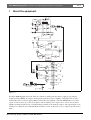
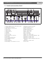
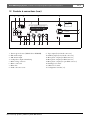
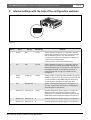
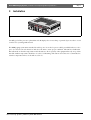
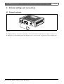
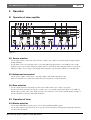
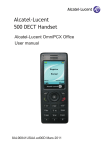
Plena BGM/Paging System
Installation and Operating Manual
en
LBB 1970
Plena BGM/Paging System | Installation and Operating Manual | Important safeguards
en | 3
Important safeguards
1 Read instructions - All the safety instructions for use
should be read before the system is operated.
2 Retain instructions - The safety instructions and
instructions for use should be retained for future
reference.
3 Heed warnings - All warnings on the unit and in the
operating instructions should be adhered to.
4 Follow instructions - All operating instructions and
instructions for use should be followed.
5 Cleaning - Unplug system units from the mains outlet
before cleaning. Do not use liquid cleaners or aerosol
cleaners. Use a damp cloth for cleaning.
6 Attachments - Do not use attachments not
recommended by the product manufacturer as they may
cause hazards.
7 Water and Moisture - Do not use this unit near water, for
example near a bathtub, washbowl, kitchen sink, or
laundry basket, in a wet basement, near a swimming
pool, in an unprotected outdoor installation or any area
which is classified as a wet location.
8 Accessories - Do not place this unit on an unstable stand,
tripod, bracket or mount. This unit may fall, causing
serious injury to a person and serious damage to the
unit. Use only a stand, tripod, bracket or mount
recommended by the manufacturer, or sold with the
product. Any mounting of the unit should follow the
manufacturer's instructions, and should use a mounting
accessory recommended by the manufacturer. An
appliance and cart combination should be moved with
care. Quick stops, excessive force, and uneven surfaces
may cause the appliance and cart combination to
overturn.
9 Ventilation - Openings in the enclosure, if any, are
provided for ventilation and to ensure reliable operation
of the unit and to protect it from overheating. These
openings must not be blocked or covered. The unit
should not be placed in a built-in installation unless
proper ventilation is provided or the manufacturer's
instructions have been adhered to.
10 Power sources - Units should be operated only from the
type of power source indicated on the marking label. If
you are not sure of the type of power supply you plan to
use, consult your appliance dealer or local power
company. For units intended to operate from battery
power, or other sources, refer to the "Installation and
User Instructions".
11 Grounding or polarisation - This unit may be equipped
with a polarised alternating current line plug (a plug
having one blade wider than the other). This plug will fit
into the power outlet only one way. This is a safety
feature. If you are unable to insert the plug fully into the
outlet, try reversing the plug. If the plug still fails to fit,
contact your electrician to replace your obsolete outlet.
Do not defeat the safety purpose of the polarised plug.
Alternatively, this unit may be equipped with a 3-wire
grounding type plug having a third (grounding) pin.
This plug will only fit into a grounding-type power
outlet. This is a safety feature. If you are unable to insert
the plug into the outlet, contact your electrician to
replace your obsolete outlet. Do not defeat the safety
purpose of the grounding-type lug.
Bosch Security Systems | 2003-09 | 3922 988 25012en
12 Power-Cord Protection - Power supply cords should be
routed so that they are not likely to be walked on or
pinched by items placed upon or against them, paying
particular attention to cords and plugs, convenience
receptacles, and the point where they exit from the
appliance.
13 Overloading - Do not overload outlets and extension
cords as this can result in a risk of fire or electrical shock.
14 Object and Liquid Entry - Never push objects of any
kind into this unit through openings as they may touch
dangerous voltage points or short-out parts that could
result in a fire or electric shock. Never spill liquid of any
kind on the unit.
15 Servicing - Do not attempt to service this unit yourself as
opening or removing covers may expose to dangerous
voltage or other hazards. Refer all servicing to qualified
service personnel.
16 Damage Requiring Service - Unplug the unit from the
outlet and refer servicing to qualified service personnel
under the following conditions:
• When the power-supply cord or plug is damaged.
• If liquid has been spilled, or objects have fallen into
the unit.
• If the unit has been exposed to rain or water.
• If the unit does not operate normally by following
the instructions for use. Adjust only those controls
that are covered by the instructions for use, as an
improper adjustment of other controls may result in
damage and will often require extensive work by a
qualified technician to restore the units to their
normal operation.
• If the unit has been dropped or the unit has been
damaged.
• When the unit exhibits a distinct change in
performance; this indicates a need for service.
17 Replacement Parts - When replacement parts are
required be sure the service technician has used
replacement parts specified by the manufacturer or parts
which have the same characteristics as the original part.
Unauthorised substitutions may result in fire, electric
shock or other hazards.
18 Safety Check - Upon completion of any service or
repairs to the units, ask the service technician to perform
safety checks to determine that the unit is in proper
operating condition.
19 Lightning - For added protection of the units during a
lightning storm, or when it is left unattended and unused
for long periods of time, unplug it from the wall outlet
and disconnect the cable system. This will prevent
damage to the unit due to lightning and power-line
surges.
Plena BGM/Paging System | Installation and Operating Manual | About this manual
en | 4
About this manual
This manual provides all the information required to install and operate the unit.
Conventions
Warning
Follow these instructions to prevent personal injury.
Caution
Follow these instructions to prevent damage to the equipment.
Note
Read these instructions for tips and other useful information.
Safety precautions
Warning
Do not open the unit when it is connected to the mains. The unit contains non-insulated parts, which can
cause electric shock.
Caution
There are no user-serviceable parts inside the unit. Service must be done by qualified personnel.
Bosch Security Systems | 2003-09 | 3922 988 25012en
Plena BGM/Paging System | Installation and User Instructions | Table of contents
en | 5
Table of contents
Important safeguards..........................................................................................................................................................3
About this manual ..............................................................................................................................................................4
Safety precautions...............................................................................................................................................................4
Table of contents ................................................................................................................................................................5
1 About the equipment ........................................................................................................................................................7
1.1
Controls and connections (front) .............................................................................................................................8
1.2
Controls & connections (rear) ..................................................................................................................................9
2 Internal settings with the help of the configuration switches ......................................................................................10
3 Installation ........................................................................................................................................................................11
4 External settings and connections .................................................................................................................................12
4.1
Connect antennas ...................................................................................................................................................12
4.2
Priority/VOX activated microphone ....................................................................................................................13
4.3
Microphones 2 and 3, auxiliary inputs and tape output .....................................................................................14
4.4
Loudspeakers ...........................................................................................................................................................14
4.5
Mains connection ....................................................................................................................................................16
5 Operation .........................................................................................................................................................................17
5.1
Operation of mixer amplifier ................................................................................................................................17
5.1.1 Source selection .................................................................................................................................................17
5.1.2 Volume and tone control ..................................................................................................................................17
5.1.3 Zone selection ....................................................................................................................................................17
5.2
Operation of tuner ..................................................................................................................................................17
5.2.1 Station selection .................................................................................................................................................17
5.2.2 Programming ......................................................................................................................................................18
5.3
Operation of CD-player .........................................................................................................................................18
5.3.1 Track selection ...................................................................................................................................................18
5.3.2 Programming ......................................................................................................................................................19
5.4
Creation of MP3 CD-R's ........................................................................................................................................19
6 Technical data ..................................................................................................................................................................20
6.1
Electrical ..................................................................................................................................................................20
6.2
Performance ............................................................................................................................................................20
6.3
Inputs ........................................................................................................................................................................20
6.4
Tuner ........................................................................................................................................................................20
6.5
CD-player ................................................................................................................................................................21
6.6
Outputs .....................................................................................................................................................................21
6.7
Environmental conditions ......................................................................................................................................21
6.8
General .....................................................................................................................................................................21
Bosch Security Systems | 2003-09 | 3922 988 25012en
Plena BGM/Paging System | Installation and User Instructions | Table of Contents
Bosch Security Systems | 2003-09 | 3922 988 25012en
en | 6
Plena BGM/Paging System | Installation and Operating Manual |About the equipment
1
en | 7
About the equipment
Chime
S401-1
Chime
S401-3
Vox
Priority Control
S401-2
S401-4
1
Mic 1
Tone
S401-5 Phantom power
Master
2
Mic 2
S401-6
O
S401-7
3
Mic 3
Ducking
Music
S101
Aux
Ant
FM
AM
ASIA/USA
EUROPE
AM
M.C.U.
FM
CD
Keypad/LCD
Control Bus
M.C.U.
Servo
Drive
Keypad/LCD
100V
100V
70V
50V S801
35V
25V
18V
0V
S802
0
100V
0
0
Call/music
0
100V
0
Call only
8Ohm
VU
8Ohm
0
100V
70V
50V S803
35V
25V
18V
S804
0
0
Call/music
0
0
8Ohm
0
100V
0
Z1
0
8Ohm
0
Z2
115/230V
F1
F2
Call active
+B
T2.5L250V(230V~)
T5L250V(115V~)
15L
LED
Call active
Figure 1.1
The Plena BGM/Paging System is the all-in-one solution for making announcements, paging people and play
background music (BGM). It comprises an integrated 120 W mono mixer amplifier, a CD-player that can play
normal audio-CD's as well as long play MP3-encoded CD's and a digitally controlled AM/FM-tuner for accurate
capture of radio stations. Up to three microphones and an auxiliary source signal can be connected to the mixer
amplifier and mixed, with priority or VOX switching available for the main microphone. The output signal can be
switched to two different zones with individual attenuation control. A third zone receives only priority calls and no
music.
Bosch Security Systems | 2003-09 | 3922 988 25012en
Plena BGM/Paging System | Installation and Operating Manual |About the equipment
en | 8
1.1 Controls and connections (front)
12 3 4 5 6 7
8
9
10
11
12
Plena BGM/Paging System
Repeat
FM/AM
Program
Scan
13
14
15
0 dB
-6 dB
-20 dB
CD/MP3
Folder
1
M1/6
M2/7
M3/8
Select
2
M4/9
M5/10
Shift
Zon e 1
Program
Zon e 2
16
CD/Tuner
Master
Aux
Power
0
0
-9
3
-12
-15
0
31 30
29 28
0
27
26
-6
-9
-12
-3
0dB
-6
-3
0dB
-15
0
25 24
23
22
21
20 19
18
17
Figure 1.2
1
2
3
4
5
6
7
8
9
10
11
12
13
14
15
16
VU-meter (LED's for -20, -6, 0 dB and Power ON)
CD MP3 folder selection key
CD program key for track selection
CD repeat key
CD previous key
CD pause/play key
CD display
CD next key
CD stop/eject key
Tuner memory keys 1-5 and 6-10
Tuner display
Tuner frequency up/down keys
Tuner FM/AM selection key
Tuner scan key
Tuner program key
Tuner shift key to select memory 1-5 or 6-10
Bosch Security Systems | 2003-09 | 3922 988 25012en
17
18
19
20
21
22
23
24
25
26
27
28
29
Microphone 1 priority active LED
Output attenuator for zone 2
Zone 2 selection button
Output attenuator for zone 1
Zone 1 selection button
Master volume control
Tone control (bass)
Tone control (treble)
Music source volume control
Music source selection button (CD/tuner - Aux)
Microphone 3 volume control
Microphone 2 volume control
Microphone 1 input (6.3 mm phone jack socket/
balanced)
30 Microphone 1 volume control
31 Power on/off
Plena BGM/Paging System | Installation and Operating Manual |About the equipment
en | 9
1.2 Controls & connections (rear)
1
2
3
4
5
115V
Call Only
FM
ASIA/USA
Switch
1
2
3
4
5
6
7
0
100V 0 100V 0
Off(0)
Mix
Mix
Chime off
Speech filter
Phantom off
Phantom off
Phantom off
Zone 2Call/BGM Call Active
Apparatus delivered
connected for 230V~
LBB 1970/00
8900 197 00005
115/230V~,59/60Hz
Max. output power 180W
Rated output power 120W
WK.
S/N
AM
EUROPE
On(1)
Priority
Vox
Chime active
Flat
Phantom on
Phantom on
Phantom on
Zone 1Call/BGM
230V
Mic.
1 rear
1 front
1 rear
1
1 rear
2
3
3
+
1
5
2
4
100 V 0
0
8
-
Rated input
power:400VA
Line fuse T2.5L250V(230V~)
T5L250V(115V~)
1
3
2
14
8
GND
-2
5
Warning
This apparatus must be earthed
1234567
16
Chimen
Ducking
1
15 14
2
13
12
3
11 10
Aux In
9
8
Figure 1.3
1
2
3
4
5
6
7
8
Tuner region selection (ASIA/USA or EUROPE)
FM antenna input
AM antenna input
Loudspeaker output terminal strip
Mains voltage selection
Mains connection
Mains fuse
Earth connection screw
Bosch Security Systems | 2003-09 | 3922 988 25012en
9
10
11
12
13
14
15
16
Tape output (for 2x Cinch-connectors)
Auxiliary input (for 2x Cinch-connectors)
Microphone 3 input (for XLR-connector)
Microphone 2 input (for XLR-connector)
Microphone 1 input (for 5-pin DIN-connector)
Ducking level control
Chime level control
Configuration switches (1-7)
6
7
Plena BGM/Paging System | Installation and Operating Manual |Internal settings
2
en | 10
Internal settings with the help of the configuration switches
Anten
ASIA/
na
USA
EURO
Switch
1
2
3
4
5
6
7
On(1)
FM
PE
Call Only
Priority
Off(0)
Vox
Mix
Mic.
Chim
Mix
e
1 rear
Flat active Chim
1 front
e
Phanto
Speecoff
h filter 1 rear
Phantom on Phanto
Phantom on Phantom off 1
m on
1 rear
Phantom off 2
m off
3
Zone
1Call/
BGM
Zone
2Call/
BGM
100V
0 100
V 0
14
0
8
100V
0
3
3
5
1
5
2
4
+
2
-
Call Active
115V~
0
45 6
7
230V~
8
Appara
connectus delivere
ted for
d
230V~
GND
1
3
1 23
LBB 1970/00
8900
197
151/203V 00001
max.Out ~, 50/60HZ
Rated put power
WK. ouput power180W
120W
S/N.
Chime
Duckin
g
1
2
3
Aux
In
Rated
input
power:
Line fuse400VA
T2.5L25
T5L250 0V(230V~)
V(115V
~)
Warnin
g
This apparatus
must
be earthed
OFF
ON
1234567
Figure 2.1
Switch
ON (1)
OFF (0)
Microphone
Function
1
Priority
Mix
1 (rear)
Selects whether microphone 1, connected to the rear
DIN-socket, will have priority over microphones 2 and 3
and the background music. This will mute these
microphones and the music and will also override zone
switching and zone attenuation.
Closing contacts 4 and 5 will activate priority.
2
Vox
Mix
1 (front)
Selects whether microphone 1, connected to the front
6.3 mm phone jack socket, will be VOX activated. As
VOX activated microphone, microphone 1 will attenuate
the background music or microphones 2 and 3 to a
preset ducking level as long as you speak into the
microphone.
3
Chime
active
Chime off
1 (rear)
Selects whether a chime signal will precede a priority call,
started by microphone 1, upon closure of contacts 4 and
5 of the rear DIN-socket. Additionally, the chime level
control allows for setting the volume of the chime.
4
Flat
Speech filter
1
Selects a flat frequency response for microphone 1 or
activates a speech filter, that improves intelligibility by
attenuating the low frequencies.
5
Phantom on
Phantom off
1 (rear)
Switches the phantom power supply for microphone 1
(DIN-connection only). Phantom power should be
switched on for condenser or electret microphones (e.g.
LBB 1950) and switched off for dynamic microphones.
6
Phantom on
Phantom off
2
Switches the phantom power supply for microphone 2.
7
Phantom on
Phantom off
3
Switches the phantom power supply for microphone 3.
Bosch Security Systems | 2003-09 | 3922 988 25012en
Plena BGM/Paging System | Installation and Operating Manual |Installation
3
en | 11
Installation
Plena
0 dB
BGM/
Pagin
g Syste
Repe
m
at
-6 dB
-20 dB
Progr
am
Folde
r
1
Power
CD /M
2
P3
Select
3
FM/AM
M1/6
CD/Tu
ner
M2/7
M3/8
M4/9
2
Scan
M5/10
Aux
Progra
Maste
m
r
Zon e
1
Zon e
-12 -9
-15
2
-6
-3
0dB
-12 -9
-15
-6
-3
0dB
Figure 3.1
Carefully peel off the protective plastic film on both displays. Do not use sharp or pointed objects in order to avoid
scratches. Use your fingernails instead.
The BGM/paging system unit is intended for table-top use. It can also be put on a shelf, provided that there is a free
space of at least 10 cm on both sides of and above the unit to ensure proper ventilation. The unit has a built-in fan
that will switch on when the temperature inside the unit rises. Do not put any other equipment directly on top of this
unit. The ambient temperature should not exceed 45 °C. Mounting of the unit in 19”-racks is not recommended as
often the temperature in these racks will exceed 45 °C.
Bosch Security Systems | 2003-09 | 3922 988 25012en
Plena BGM/Paging System | Installation and Operating Manual |External settings and connections
4
en | 12
External settings and connections
4.1 Connect antennas
Ant enn
ASI A/U
SA
EUR
Switc
1
2
3
4
5
6
7
h On(1
)
Prior
ity
Vox
a
FM
OPE
Call Onl
Off(0
)
Mix
Mic.
Mix
1 rear
e Chim
1 front
e
Phan
Spee off
to
Phan m on Phan ch filter 1 rear
to
Phan m on Phan tom off 1
tom on
1 rear
to
Phan m off 2
tom off
3
y
Zone
1Ca
ll/BG
Chim
e
Flat activ
100V
0 100
V 0
14
0
8
1
5
2
4
+
2
-
M
Zone
2Ca
ll/BG
M Cal
l Acti
100V
0
3
3
5
ve
115V
0
8
45 6
7
Chim
e
~ 230V
~
Appa
ratus
connected delivered
for 230V
~
GND
1
3
1 23
Duc king
1
2
3
Aux
In
LBB 1970/
00
8900
197 00001
151/2
03V~
, 50/60
max.O
Rated utput powe HZ
r
WK. ouput powe 180W
r 120W
S/N.
Rated
input
power:
Line fuse400VA
T2.5L250V
T5L250V( (230V~)
115V~)
Warn
ing
This appara
tus must
be earthe
d
Figure 4.1
The FM input must be connected to an antenna or cable network with a COAX cable of 75 Ohm. A connector for
the FM input is provided with the unit. The AM input can be connected to the loop-antenna delivered with the unit.
Bosch Security Systems | 2003-09 | 3922 988 25012en
Plena BGM/Paging System | Installation and Operating Manual |External settings and connections
en | 13
4.2 Priority/VOX activated microphone
Antenn
a
ASIA/U
Plena
BGM
0 dB
SA
EUROP
Switch
Switch
/Pag
1
2
3
4
5
6
7
ing Sys
tem
Repeat
-6 dB
-20 dB
Program
On(1)
On(1)
FM
Call
Call Only
Only
E
Priority
Priority
Off(0)
Off(0)
Vox
Vox
Mix
Mix
Mic.
Mic.
Chim
Chim
Mix
e active Mix
11 rear
rear
Flat
Flat active
Chim
Chim
1 front
e off
front
Phanto
Phanto
Speecoff
Speec
m on
rear
on
hh filter 1 rear
Phanto
Phanto m
Phanto
Phanto filter
m on
1
on
Phanto m
Phanto
m off
off
Phanto
Phantom
m
m on
1 rear
on
rear
m off
off
Phanto
Phantom
2
m off
m
off
3
Zone
Zone
11Call/B
Call/BGM
GM
100V
100V
00 100V
100V
00
14
0
88
3
3
5
2
4
+
-
Zon
Zonee
22Call/B
Call/BGM
GM
100
100V
V 00
1
5
2
Cal
Calll Active
Active
115V~
00
45 6
7
230V~
88
Apparatu
connectes delivered
d for 230V~
GND
1
3
1 23
Folder
Chime
Ducking
1
2
1
3
Power
CD/M
2
P3
Aux
AuxIn
In
LBB 1970/00
8900
197
151/203V~00001
max.Outpu, 50/60HZ
t power
Rated
WK. ouput power180W
120W
S/N.
Rated
input
power:
400VA
Line fuse
T2.5L250
T5L250V(V(230V~)
115V~)
Select
Warning
Warning
This apparatus
3
must
FM/AM
M1/6
CD/Tuner
M4/9
Cal On
Scan
M5/10
Aux
Program
Master
Zon e
1
Zon e
Rep eat
-12 -9
-15
-6 dB
-20 dB
ly
Zone
1Call
/BGM
2
-6
-3
0dB
-12 -9
-15
Zone
-6
-3
100V
0dB
Prog
be earthed
M2/7
M3/8
2
0 dB
ram
Fold er
14
0 10
0V 0
0
8
3
3
5
100V
0
1
5
2
4
+
2
-
2Call
/BGM
0
Cal Ac
tive
8
GND
1
3
1
Power
Du ck
2
ing
1
2
3
3
Aux
In
GND
GND
6.3 mm phono jack
180 5-pole DIN
180 3-pole XLR
Figure 4.2
Microphone 1 has different operating modes:
Priority mode:
Connect the microphone to the DIN-socket at the rear of the unit and enable the priority mode with configuration
switch 1 (set to ON-position). This requires a microphone with a priority switch on contacts 4 and 5 of the 5-pin
DIN-connector, such as the table-top microphone LBB 1950. In this mode, microphone 1 will have priority over
microphones 2 and 3 and the background music. Activating this microphone will mute the other microphones and
the music and will also override zone switching and zone attenuation. Priority announcements will even be heard in
deselected zones. This mode is normally used for important (emergency) announcements. You can select a chime
signal to precede such a priority call with configuration switch 3, a speech filter with configuration switch 4 and
phantom power with configuration switch 5.
VOX mode:
Connect the microphone to the phone jack socket at the front of the unit and enable the VOX mode with
configuration switch 2 (set to ON-position). This mode will attenuate the background music or microphones 2 and 3
to a preset ducking level as long as you speak into the microphone. It is normally used with handheld microphones
like the LBC 2900/15 for making casual announcements, temporarily surpressing the music. Background music and
announcements will be heard in the selected zones. The front connection for microphone 1 does not have phantom
power for electret or condenser microphones, so a dynamic microphone must be used. A chime is not available in
this mode, but you can select the speech filter via configuration switch 4.
When no priority or VOX mode has been selected, microphone 1 will just mix with the background music or the
other microphones to the selected zones.
Bosch Security Systems | 2003-09 | 3922 988 25012en
Plena BGM/Paging System | Installation and Operating Manual |External settings and connections
en | 14
4.3 Microphones 2 and 3, auxiliary inputs and tape output
Anten
ASIA/
na
USA
EURO
Switch
1
2
3
4
5
6
7
FM
PE
Call Only
On(1)
Priority
Off(0)
Vox
Mix
Mic.
Chim
Mix
e
1 rear
Flat active Chim
1 front
e
Phanto
Speecoff
h filter 1 rear
Phantom on Phanto
Phantom on Phantom off 1
m on
1 rear
Phantom off 2
m off
3
Zone
1Call/B
GM
100V
0 100
V 0
14
0
8
1
5
2
4
+
-
Zone
2Call/B
GM
100V
0
3
3
5
2
Call Active
115V~
0
45 6
7
230V~
8
Apparat
connectus delivere
ed for
d
230V~
GND
1
3
1 23
LBB 1970/00
8900
197
151/203V 00001
max.Outp~, 50/60HZ
Rated ut power
WK. ouput power180W
120W
S/N.
Chime
Duckin
g
1
2
3
Aux
Rated
input
power:
400VA
Line fuse
T2.5L25
T5L250V0V(230V~)
(115V~)
In
Warning
This apparatus
must
V 0
0
3
be earthed
8
Aux
In
TAPE
Figure 4.3
•
•
•
Connect microphones 2 and 3 to the rear XLR-sockets. Enable phantom power for these microphones with
configuration switches 6 and 7, if you use electret or condenser microphones. These microphones just mix with
the background music.
Connect an auxiliary music source, like a tape/cassette recorder or the audio signal of a DVD player, to the
auxiliary Cinch-sockets on the rear. Stereo signals will be converted to mono.
The tape output sockets may be used for connection to a tape/cassette recorder to record microphone and
background music signals. Both sockets provide the same mono signal.
4.4 Loudspeakers
100V
VU
0V
100V
70V
50V
35V
25V
18V
0
100V
Antenna
ASIA/US
A
EUROP
Switch
1
2
3
4
5
6
7
Call/music
0
8Ohm
0
1 23
100V
0
0
7
Zone
1Call/BG
M
100V
0 100
V 0
14
0
8
1
5
2
4
+
-
Zone
2Call/BG
M Cal
l Active
100V
0
3
3
5
115V~
0
230V~
8
Apparatus
connected delivered
for 230V~
GND
1
Chime
1
2
3
Aux
LBB 1970/00
8900
197 00001
151/203V~,
max.Output 50/60HZ
Rated
power
WK. ouput power180W
120W
S/N.
Rated
input
power:
Line fuse400VA
T2.5L250V
In
T5L250V(1(230V~)
15V~)
Warning
This apparatus
must
be earthed
Zone 1
0
Call/music
0
0
8Ohm
0
8Ohm
0
Call Only
45 6
Ducking
Call Only
100V
70V
50V
35V
25V
18V
FM
E
On(1)
Priority
Off(0)
Vox
Mix
Mic.
Chim
Mix
e
1 rear
Flat active Chim
1 front
e
Phanto
Speecoff
h filter 1 rear
Phantom on Phanto
Phantom on Phantom off 1
m on
1 rear
Phantom off 2
m off
3
3
8Ohm
0
Call only
2
0
0
100V
0
100V
0
Zone 1 Call/BGM
0
0
8Ω
Zone 2 Call/BGM Call Active
100V 0
0
Call Only
8Ω
Zone 1 Call/BGM
100V 0 100V 0
0 8Ω
Zone 2 Call/BGM Call Active
100V 0
0
8Ω
Zone 2
115/230V
F1
Call active
F2
+B
T2.5L250V(230V~)
T5L250V(115V~)
8W
15L
100V
LED
Zone 1
Call active
Zone Call Only
Figure 4.4
Bosch Security Systems | 2003-09 | 3922 988 25012en
Figure 4.5
Zone 1
Zone 2
Zone 2
Plena BGM/Paging System | Installation and Operating Manual |External settings and connections
en | 15
Loudspeakers are connected via screw terminals, behind a removable plastic cover for safety. This Plena System
Amplifier has a very flexible output configuration, allowing for different groups of loudspeakers.
• Connect 100 V-loudspeakers for zone 1 to the 100 V-/0-terminals of zone 1. The selection button and the output
attenuator for zone 1 (both on the front panel) control this output. If a low impedance loudspeaker is used for
zone 1, connect it to the 8 Ohm- / 0-terminals of zone 1, but now the output level will not be affected by the
attenuator.
• Proceed in the same way for zone 2.
• Connect 100 V-loudspeakers that should receive only priority announcements from microphone 1 to the Call
Only 100 V- /0-terminals. For this, the priority mode must be enabled (see §4.2).
The Call Active terminals provide voltage free relay contacts. This contact is closed as long as a priority call is
active. This contact may be used for overriding remote volume controls or other purposes. It is switched together
with the Call Only loudspeaker zone.
Note
Ensure that the loudspeakers are wired in phase by connecting the 0-terminals of loudspeakers in the same
zone together to the amplifier 0-terminal.
Caution
Connect 100 V-loudspeakers in the same zone just in parallel, but take care that the total power of the
loudspeakers, i.e. the load, does not exceed the 120 W power rating of this Plena unit
Caution
It is not recommended to use both low impedance loudspeakers and 100 V-loudspeakers simultaneously.
Multiple low impedance loudspeakers should be connected in series or parallel so that the total impedance is
more than 8 Ohm.
Bosch Security Systems | 2003-09 | 3922 988 25012en
Plena BGM/Paging System | Installation and Operating Manual |External settings and connections
en | 16
4.5 Mains connection
Anten
ASIA/
na
USA
EURO
Switch
1
2
3
4
5
6
7
On(1)
FM
PE
Call Only
Priority
Off(0)
Vox
Mix
Mic.
Chim
Mix
e
1 rear
Flat active Chim
1 front
e
Phanto
Speecoff
h filter 1 rear
Phantom on Phanto
Phantom on Phantom off 1
m on
1 rear
Phantom off 2
m off
3
Zone
1Call/B
GM
100V
0 100
V 0
14
0
8
1
5
2
4
+
-
Zone
2Call/B
GM
100V
0
3
3
5
2
Call Active
115V~
0
45 6
7
Apparat
connectus delivere
ed for
d
230V~
1
Chime
Duckin
230V~
8
GND
3
1 23
g
1
2
3
Aux
In
LBB 1970/00
8900
197
151/203V 00001
max.Outp~, 50/60HZ
Rated ut power
WK. ouput power180W
120W
S/N.
Rated
input
power:
Line fuse400VA
T2.5L25
T5L250V0V(230V~)
(115V~)
Warning
This apparatus
must
be earthed
115V
~ 23
0V~
Appa
rat
connec us delivere
ted for
d
230V
~
LBB 19
8900 70/00
19
151/2 7 00001
03
max.O V~, 50/60
Rated utput powe HZ
r
WK. ouput powe 180W
r 120W
S/N.
Rated
inp
power: ut
Line fus400VA
e T2.5L
25
T5L250 0V(230V~
V(115V
~)
Warnin
g
This app
aratus
must
be ear
thed
Figure 4.6
Use the supplied mains cord to connect the system to the mains supply.
Note
If necessary set the switch 115/230 V to the required voltage using a sharp object, e.g. a small screwdriver.
Bosch Security Systems | 2003-09 | 3922 988 25012en
Plena BGM/Paging System | Installation and Operating Manual |Operation
5
en | 17
Operation
5.1 Operation of mixer amplifier
12 3 4 5 6 7
8
9
10
11
12
Plena BGM/Paging System
Repeat
FM/AM
Program
Scan
13
14
15
0 dB
-6 dB
-20 dB
CD/MP3
Folder
1
M1/6
M2/7
M3/8
Select
2
M4/9
M5/10
Shift
Zon e 1
Program
Zon e 2
16
CD/Tuner
Master
Aux
Power
0
0
-9
3
-12
-15
0
31 30
29 28
0
27
26
-6
-9
-12
-3
0dB
-6
-3
0dB
-15
0
25 24
23
22
21
20 19
18
17
Figure 5.1
5.1.1 Source selection
•
•
Use the input volume controls (30, 28, 27 and 25) to balance the sound level of the microphone inputs and the
background music.
Use the music source selection button (26) to select the built-in CD-player/tuner or an auxiliary source. If the
auxiliary source is selected, the CD-player and the tuner are switched off. If the CD-player/tuner is selected, the
CD-player will be active as long as it is playing. If the CD-player stops, the tuner will take over automatically.
5.1.2 Volume and tone control
•
•
Use the master volume control (22) to control the volume of the music/microphone mix.
The bass and treble tone controls (23 and 24) affect the microphones as well as the music.
5.1.3 Zone selection
•
•
Use the output attenuators (20 and 18) to balance the sound level in zones 1 and 2, respectively.
Use the zone selection buttons (21 and 19) to switch a zone on or off. The priority microphone active LED (17)
indicates that a priority call is active. Such a priority call overrides the zone selection and attenuation settings. A
priority call addresses all zones with 0 dB attenuation.
5.2 Operation of tuner
5.2.1 Station selection
•
•
Use the tuner FM/AM selection key (13) to choose between FM and AM reception.
Use the tuner frequency up/down keys (12) to step up or down in frequency. Prolonged pressing makes the tuner
search for the next station.
Bosch Security Systems | 2003-09 | 3922 988 25012en
Plena BGM/Paging System | Installation and Operating Manual |Operation
en | 18
5.2.2Programming
•
•
Save the selected radio station as a preset by pressing the tuner program key (15).
Press the tuner memory keys M1/6 to M5/10 (10) for memory position 1 to 5.
Or
•
•
Press the tuner program key (15), the tuner shift key (16) and the tuner memory keys M1/6 to M5/10 (10) for
memory position 6 to 10.
The tuner display (11) shows 'MEMORY' during this process. Both for AM and FM, 10 presets are available.
Saved presets are selected by pressing the tuner memory keys M1/6 to M5/10 (10) or by pressing the tuner shift key
(16) followed by M1/6 to M5/10. For easy selection, pressing the tuner scan key (14) monitors the presets by
selecting all 10 presets sequentially for 5 seconds.
5.3 Operation of CD-player
5.3.1 Track selection
Note
After inserting a new CD, the CD-player detects the type of CD and shows it on the CD display (7): 'CD' for
an audio-CD or 'MP3' for a disc containing MP3-files.
Note that loading of MP3-CD's may take longer, depending on the number of tracks and subdirectories, as an
internal table of contents is made. The MP3-files in the root directory and in the subdirectories are all put in
separate folders for easy track selection. The folder number is indicated on the display, followed by the track
number and the time.
For track selection on audio-CD's proceed as follows:
• Shortly press the CD previous key (5) and/or the CD next key (8) to select the track. Prolonged pressing results
in fast reverse or fast forward.
• Use the CD pause/play key (6) to pause or to play (resume playing).
• Use the CD stop/eject key (9) to stop playing (press once) and/or to eject the CD (press twice).
For track selection on MP3-CD's first select the folder that contains the track. Proceed as follows:
• Press the CD MP3 folder selection key (2).
• Press the CD previous key (5) and/or the CD next key (8). The display shows 'FOLDER' during this process.
Pressing the CD MP3 folder selection key once more resumes the track selection mode in the selected folder.
U
Bosch Security Systems | 2003-09 | 3922 988 25012en
U
U
By repeatedly pressing the CD repeat key (4) you select the following modes:
- Playing all tracks (MP3: in all folders) and stop.
- Repeating the current track. The display shows '1'.
- Repeating all MP3-tracks within the current folder. The display shows ' '.
- Repeating all tracks (MP3: in all folders). The display shows '
'.
- Random playing of tracks (MP3: in all folders). The display shows 'RANDOM'.
Plena BGM/Paging System | Installation and Operating Manual |Operation
en | 19
If a MP3-CD is stopped and loaded again, the player will resume playing where it was stopped. In this way it is
avoided that only the first part of a very long MP3-CD is played over and over again each day. If, however, an
audio-CD is stopped and loaded again, it just starts with track 1.
5.3.2Programming
To program a playlist selection:
• Press the CD program key (3).
• Select a track by pressing the CD previous key (5) and/or the CD next key (8). In the case of a MP3-CD folder
selection is possible, as described above.
• Press the CD repeat key (4) to store the first track and step to the next track of the playlist, open for selection.
• Repeat this process until the playlist is finished.
• Finally press the CD pause/play key (6) to start playback of the playlist.
5.4 Creation of MP3 CD-R's
You can make your own MP3 CD-R's (CD-ROM's) on a normal PC with a CD-burner. Numerous programs for this
purpose are available as freeware or shareware. Some websites to download from are: www.mp3.com,
www.download.com, www.shareware.com and www.zdnet.com.
Search there, or in a general search program as www.google.com, for 'CD-ripper'. You can collect your MP3-files in
different subdirectories or folders on your PC and transfer these files to the CD-R. Always use the file name
extension .mp3. Constant MP3-bit rates (CBR) of 32 - 320 kbps are supported, as well as variable bit rate (VBR) files.
Note
As the reflectivity of a CD-RW (CD-Rewritable) is far below that of a CD and a CD-R, playback of CD-RW's
is not guaranteed. On the CD-R the ISO-9660 file system should be used. Do not use the UDF file system.
Bosch Security Systems | 2003-09 | 3922 988 25012en
Plena BGM/Paging System | Installation and Operating Manual |Technical data
6
Technical data
6.1 Electrical
Mains voltage
Max mains power consumption
Max/rated output power
230/115 Vac, ±10%, 50/60 Hz
400 VA
180 W/120 W
6.2 Performance
Frequency response
Distortion
Bass control
Treble control
60 Hz - 18 kHz (+1/-3 dB @ -10 dB ref. rated output)
<1% @ rated output, 1 kHz
-8/+8 dB @ 100 Hz
-8/+8 dB @ 10 kHz
6.3 Inputs
Input 1 (5-pin DIN, balanced with phantom power, 6.3 mm phone jack)
Sensitivity
1 mV
Impedance
>1 kOhm
S/N (flat at max volume)
63 dB
S/N (flat at min volume/muted)
75 dB
Headroom
25 dB
Speech filter
-3 dB @ 315 Hz, high-pass, 6 dB/oct
Phantom power supply (on 5-pin DIN only)
12 V
VOX (on 6.3 mm phone jack)
trigger level 0.4 mV
attack time 200 ms
release time 2 s
ducking level adjustable
Input 2 and 3 (3-pin XLR, balanced with phantom power)
Sensitivity
1 mV
Impedance
>1 kOhm
S/N (flat at max volume)
63 dB
S/N (flat at min volume/muted)
75 dB
Headroom
25 dB
Phantom power supply
12 V
Auxiliary input (Cinch, stereo converted to mono)
Sensitivity
200 mV
Impedance
22 kOhm
S/N (flat at max volume)
70 dB
S/N (flat at min volume/muted)
75 dB
Headroom
25 dB
6.4 Tuner
Tuning range
FM
AM
87.5 - 108 MHz (EUROPE, 50 kHz)
87.5 - 108 MHz (ASIA/AMERICA, 100 kHz)
531 - 1602 kHz (EUROPE, 9 kHz)
530 - 1610 kHz (ASIA/AMERICA, 10 kHz)
Bosch Security Systems | 2003-09 | 3922 988 25012en
en | 20
Plena BGM/Paging System | Installation and Operating Manual |Technical data
Sensitivity
FM
AM
2 µV (26 dB S/N)
30 µV (20 dB S/N)
Performance
Frequency response
Distortion
S/N
30 Hz - 15 kHz (+1/-3 dB, FM)
<1%
> 63 dB (1 mV, FM)
6.5 CD-player
Audio CD
Frequency response
Distortion
S/N
20 Hz - 20 kHz (+1/-3 dB)
<0.1%
>80 dB
MP3 CD/CD-R
Supported bit rates
CBR 32 kbps - 320 kbps and VBR, mono and stereo
General
Data buffer (shock protection)
Lifetime
Memory for track selection
8 MByte
>10.000 CD play cycles
999 tracks (MP3), 99 tracks (audio CD)
6.6 Outputs
Tape output (Cinch, 2x mono)
Nominal level
Impedance
350 mV
1 kOhm
Loudspeaker outputs
100 V outputs
Zone output attenuation taps
8 Ohm outputs
120 W rated (all zones together)
100/70/50/35/25/18 V for 0/-3/-6/-9/-12/-15 dB
18 V (40 W rated per zone)
Call active relay
Contacts
voltage free, max 100 V, 2 A
6.7 Environmental conditions
Operating temperature range
Storage temperature range
Relative humidity
+5 to +45 °C
-25 to +55 °C
<95%
6.8 General
EMC emission
EMC immunity
Safety
Acoustic noise level of fan
Dimensions
Weight
Rack building
acc. to EN 55103-1
acc. to EN 55103-2
acc. to EN 60065
<35 dBSPL @ 1 m, temperature controlled
144 x 430 x 320 mm (19” wide, 3U high)
approx. 11.6 kg
not recommended
Bosch Security Systems | 2003-09 | 3922 988 25012en
en | 21
Plena BGM/Paging System | Installation and Operating Manual |
Bosch Security Systems | 2003-09 | 3922 988 25012en
en | 22
For more information visit
www.boschsecuritysystems.com
© Bosch Security Systems B.V.
Data subject to change without notice
2003-09 | 3922 988 25012en