1
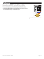
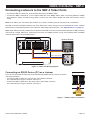
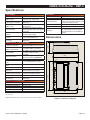
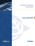
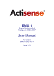
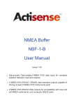
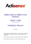
NBF-3
NMEA® 0183 Buffer
User Manual
For all variants:
NBF-3-BAS, Rev A
Issue 1.01
NMEA 0183 Buffer - NBF-3
Contents
Company Information
Important Notices
4
5
Product Overview
6
Installation Warnings
Mounting the NBF-3
8
9
Trademarks and Registered Trademarks
Fair Use Statement
Technical Accuracy
Product Registration
Product Guarantee
Product Disposal
Features
Figure 1 - Example of a Typical NBF-3 Installation
Package Contents
Bulkhead Mounting
DIN Rail Mounting
Figure 2 - Mounting Options
5
5
5
5
5
5
6
6
7
9
9
9
Connecting Power to the NBF-3
10
NMEA 0183 Listener and Talker Designations
Connecting to the NBF-3 Listener Port
10
11
Connecting Listeners to the NBF-3 Talker Ports
13
Troubleshooting Guide
14
Specifications
Dimensions
15
15
NBF-3 Product Order Codes
16
Figure 3 - Power Connection Diagram
Connecting an NMEA Talker
Powering the Talker from the NBF-3 Listener Port
Figure 4 - Listener Port Wiring Diagram
Connecting an RS232 Device (PC) as a Talker Figure 5 - RS232 Talker Connection
Figure 6 - Talker Port Wiring Diagram
Connecting an RS232 Device (PC) as a Listener
Figure 7 - RS232 Listener Connection
LED Indicators
No Data on an Output
Technical Support and the Returns Procedure
Figure 8 - Dimension Diagram
© 2013 Active Research Limited
10
11
11
11
12
12
13
13
13
14
14
14
15
Page 3
Company Information
Active Research Ltd
Unit 5 Wessex Trade Centre
Ringwood Road
Poole, Dorset
UK, BH12 3PF
Telephone: +44 (0)1202 746682
Email: [email protected]
Web: www.actisense.com
© 2013 Active Research Limited
Page 4
NMEA 0183 Buffer - NBF-3
Important Notices
The NBF-3 complies with the Electromagnetic Compatibility requirements according to EN60945. The unit
should always be used in conjunction with appropriate CE marked, shielded cable and connectors to ensure
compliance. A declaration of conformity is available for download at www.actisense.com.
Trademarks and Registered Trademarks
Actisense® and the Actisense logo are registered trademarks of Active Research Limited. All other trademarks are the
property of their respective owners.
The NMEA® name and NMEA logo are copyright held by the NMEA. All uses in this manual are by permission and no
claim on the right to the NMEA name or logo are made in this manual.
Fair Use Statement
The contents of this manual may not be transferred or copied without the express written permission of Active Research
Limited.
Copyright © 2013 Active Research Ltd. All rights reserved.
Technical Accuracy
To the best of our knowledge the information contained in this document was correct at the time it was produced. Active
Research Ltd cannot accept liability for any inaccuracies or omissions.
The products described in this manual and the specifications thereof may be changed without prior notice. Active
Research Ltd cannot accept any liability for differences between the product and this document. To check for updated
information and specifications please contact Active Research Limited.
Active Research Limited will not be liable for infringement of copyright, industrial property rights, or other rights of a third
party caused by the use of information or drawings described in this manual.
Product Registration
Please register your product via the online form www.actisense.com/support/prodreg.html.
Your product package includes a unit serial number. Your registration will assist Actisense Support to link your product
to your details, simplifying any future assistance you may require.
Product Guarantee
This product comes with a three year ‘return to base’ guarantee. If you suspect that the unit is faulty please refer to the
“Troubleshooting Guide” on page 14.
It is a requirement of the guarantee that all installations of electronic equipment follow the NMEA 0400 specification. Any
connection to a battery or power supply must meet the mandatory essential safety requirements that may be imposed
by local regulatory agencies.
Actisense products are intended for use in a marine environment, primarily for below deck use. If a product is to be used
in a more severe environment, such use may be considered misuse under the Active Research Limited guarantee.
Product Disposal
Please dispose of this product in accordance with the WEEE Directive. The product should be taken to a
registered establishment for the disposal of electronic equipment.
© 2013 Active Research Limited
Page 5
Product Overview
The Actisense NMEA Buffer (NBF-3) distributes up to six identical data streams from a single source. Signals are
buffered to ensure each receiver has the required voltage levels. Isolation on the input and each output allows nonisolated devices to be connected safely. The ability to power the source device allows the option of a single cable to
connect both power and data to the source device.
Features
•
•
•
•
•
•
•
•
•
•
•
•
Works automatically with any serial protocol, including NMEA 0183
Works automatically at any baud rate up to 115200 Baud
Galvanic opto-isolation on the input meets the latest NMEA 0183 specification
ISO-Drive™ provides galvanic isolation on the outputs to prevent ground loops
Compatible with all NMEA 0183 versions without requiring configuration
Inputs and outputs compatible with RS422 and RS232 devices
DIN rail mountable
Pluggable screw terminals for quick and easy installation and diagnostics
Power and data input indicator LEDs
Amplification of weak input signals
Power feed for single cable installation to the NMEA Talker
Waterproof electronics and splash proof connections
Note: Not to be used as wiring instructions
Listeners
12v
Optional power feed
500mA max
Latitude
50˚74’03”
Longitude
-1˚94’95”
Latitude
50˚74’03”
Longitude
-1˚94’95”
Talker
Figure 1 - Example of a Typical NBF-3 Installation
© 2013 Active Research Limited
Page 6
NMEA 0183 Buffer - NBF-3
Package Contents
1 x NBF-3-BAS with pluggable screw terminals.
1 x Actisense CD in sleeve (Documents and Software)
1 x NBF-3 User Manual
1 x Connector cover
4 x Connector cover screws
4 x Mounting screws
Accessories Supplied Separately
DIN-KIT-1 mounting kit for use with DIN rails
© 2013 Active Research Limited
Page 7
Installation Warnings
!
All warnings and notices must be followed to ensure the correct operation of the NBF-3. Incorrect
installation may invalidate the guarantee.
It is highly recommended that all of the installation instructions are read before commencing the installation.
There are important warnings and notes throughout the manual that should be considered before the
installation is attempted.
Warning 1: Accuracy
The Actisense NBF-3 is designed to accurately transfer data from the input to its outputs. No data integrity checking is
performed by the NBF-3. Any incomplete, inaccurate or corrupt data received on the NBF-3 input will be duplicated to
the NBF-3 outputs. The accuracy of the data is dependant on the NMEA Talker or other source device that generated
the data.
Warning 2: Installation and Operation
This product must be installed and operated in accordance with the instructions provided. Failure to do so could result
in personal injury, damage to your boat and/or poor product performance.
Warning 3: Installation Code of Practice
When wiring the power supply to the NBF-3 ensure the isolation switch is off. Wiring the NBF-3 while the connection is
live may damage the NBF-3 and is in breach of the guarantee. Any connection to a battery or power supply must meet
the mandatory essential safety requirements that may be imposed by local regulatory agencies.
All wiring should be in accordance with the requirements of the NMEA 0400 installation specification.
Warning 4: Mounting Requirements
Select a flat location to mount the NBF-3. Mounting on a contoured surface may cause damage to the case.
Do not mount the NBF-3 while the device is powered.
Do not mount the NBF-3 while the cable harness is connected.
Note that the terminals are pluggable for easy disconnection when mounting or removing the NBF-3.
Warning 5: Mounting Locations
Do not mount the NBF-3 in the same plane as transmitting or receiving antennas.
Mounting the NBF-3 close to a standard or steering compass may affect the operation of the compass. This distance will
vary dependant on the compass type, typically a minimum of 1 meter (3ft) is recommended.
© 2013 Active Research Limited
Page 8
NMEA 0183 Buffer - NBF-3
Mounting the NBF-3
Bulkhead Mounting
Method:
• Use the NBF-3 as a template to locate and mark the drill holes for mounting. Do not attempt to drill the holes while the
NBF-3 is in position
• Refer to “Warning 5: Mounting Locations” on page 8
• Four M3.5 stainless steel pan-head screws are provided with the NBF-3 for mounting to the bulkhead. If these screws
are lost, suitable alternatives may be used. Note: Using larger or counter sunk screws can damage the housing and
invalidate the guarantee
• Secure directly to a bulkhead using the mounting screws provided with the unit
Refer to the “Dimensions” on page 15.
DIN Rail Mounting
Requirements:
• An Actisense DIN Rail Kit (optional accessory, purchased separately: DIN-KIT-1)
• A top hat rail, type EN 50 022 or a G section rail, type EN 50 035
Mounting on a different rail type or using an alternative mounting kit or screw may breach the terms and conditions of
the guarantee.
Method:
• Refer to “Warning 5: Mounting Locations” on page 8
• Attach the mounting kit to the base of the NBF-3 with the kit supplied screws. There is provision to mount the NBF-3
vertically or horizontally (recommended). Using alternative screws may not be reliable or may result in damage to the
housing and invalidate the guarantee
Bulkhead Mounting
DIN Rail Mounting
M3.5 s/s self-tapping
pan-head screw (4 in pack)
DIN rail clip (2 in pack)
Counter sunk PT screw (4 in pack)
Figure 2 - Mounting Options
© 2013 Active Research Limited
Page 9
Connecting Power to the NBF-3
• Refer to “Warning 3: Installation Code of Practice” on page 8.
• The NBF-3 requires a power source providing between 10 and 35
Volts DC.
• Connect the positive supply wire to the ‘PWR +VE’ screw terminal
of the NBF-3.
• Connect the negative / ground supply wire to the ‘PWR GND’
screw terminal of the NBF-3.
• The NBF-3 should only be used with standard negative ground DC
systems.
• The input supply connection has continuous reverse polarity and
ESD protection.
Note: This protection is only on the power input, for details of the
power output refer to “Powering the Talker from the NBF-3
Listener Port” on page 11.
• Once all connections have been made, turn on the supply. For
details on the power indicator, refer to “NBF-3 Power LED (Blue)”
on page 14.
®
Fuse Box
Battery
Figure 3 - Power Connection Diagram
NMEA 0183 Listener and Talker Designations
The NMEA have updated the NMEA 0183 specification to ensure a consistent naming convention is used for labelling
ports. The designation follows the same rules as used for Rx and Tx labelling but uses Talker and Listener instead.
The input / receiving (Rx) port will be labelled as a ‘Listener’ port.
The output / transmitting (Tx) port will be labelled as a ‘Talker’ port.
When a port is labelled ‘Listener’ it is an input and when it is labelled ‘Talker’ it is an output.
© 2013 Active Research Limited
Page 10
NMEA 0183 Buffer - NBF-3
Connecting to the NBF-3 Listener Port
Connecting an NMEA Talker
The input to the NBF-3 is labelled ‘Listener’ and this is where the NMEA Talker should be connected.
• Connect the NBF-3 Listener A/+ to the positive data line of the NMEA Talker.
• Connect the NBF-3 Listener B/- to the negative data line of the NMEA Talker.
This is the ground / common connection of the Talker for RS232 or NMEA 0183 version 1 Talkers.
• For details on the data indicator, refer to “NBF-3 Listener Port Data LED (Green)” on page 14.
Note: Only one NMEA Talker can be connected to the NBF-3 Listener port. Multiple NMEA Talkers require an NMEA
Multiplexer to be fitted, see www.actisense.com/NDC-4.
Note: The NMEA Listener port is fully isolated and is compatible with all versions of NMEA 0183 and with RS422,
RS232 and RS485 voltage levels, see “Specifications” on page 15.
Powering the Talker from the NBF-3 Listener Port
It is also possible to power the NMEA Talker from the NBF-3. The NBF-3 power connection is routed to the Listener port
PWR OUT connection via a self-resettable fuse. A maximum of 500mA can be provided to the NMEA Talker at the
voltage supplied to the NBF-3.
• Connect the NBF-3 +VE OUT to the positive supply input of the NMEA Talker.
• Connect the GND OUT of the NBF-3 to the negative supply or ground input of the NMEA Talker.
Note: The current provided is temperature dependant, see “Specifications” on page 15.
Note: If the NBF-3 power supply is incorrectly wired (reverse polarity), the Listener power output voltage will also be
reverse polarity and could potentially harm any connected equipment. However the NBF-3 electronics are always
protected against reverse polarity supply faults.
Talker Device
®
Talker data: Negative
Talker data: Positive
Talker power: Negative
Latitude
50˚74’03”
Longitude
-1˚94’95”
Talker power: Positive
Figure 4 - Listener Port Wiring Diagram
© 2013 Active Research Limited
Page 11
Connecting an RS232 Device (PC) as a Talker
A PC can be connected the same way as an RS232 type NMEA Talker.
• Connect the NBF-3 Listener A/+ to the Tx pin of the RS232 connector.
On a standard 9 pin D-type connector, this is pin 3.
• Connect the NBF-3 Listener B/- to the Ground pin of the RS232 connector.
On a standard 9 pin D-type connector, this is pin 5.
®
5432 1
Figure 5 - RS232 Talker Connection
© 2013 Active Research Limited
Page 12
NMEA 0183 Buffer - NBF-3
Connecting Listeners to the NBF-3 Talker Ports
• Connect the NBF-3 Listener A/+ to the positive data line of the NMEA Talker.
• Connect the NBF-3 Listener B/- to the negative data line of the NMEA Talker. When connecting RS232 or NMEA
0183 version 1 Talkers, this will be the ground / common line of the Talker. Always check the manual for the correct
wiring.
Note: All six Talker port connections are identical. Any number of Talker ports can be used in any combination.
The NBF-3 can drive multiple Listeners from each Talker port. Check the input current requirements of each Listener
and ensure the combined total does not exceed the “Talker Output Current Drive”, see “Specifications” on page 15.
Note: Each Talker port is fully isolated, but be aware that the NBF-3 will not provide isolation between multiple Listeners
connected to a single Talker port. Connecting more than one NMEA Listener is only recommended when all NMEA
Listeners are known to have isolated inputs.
Listener Devices
Latitude
50˚74’03”
Longitude
-1˚94’95”
®
Listener data: Negative
Listener data: Positive
Listener data: Negative
Listener data: Positive
Figure 6 - Talker Port Wiring Diagram
Connecting an RS232 Device (PC) as a Listener
A PC can be connected the same way as an RS232 type NMEA Listener. The PC should be
connected as follows:
• Connect the NBF-3 Talker A/+ to the Rx pin of the RS232 connector.
On a standard 9 pin D-type connector, this is pin 2.
• Connect the NBF-3 Talker B/- to the Ground pin of the RS232 connector.
On a standard 9 pin D-type connector, this is pin 5.
5432 1
Figure 7 - RS232 Listener Connection
© 2013 Active Research Limited
Page 13
Troubleshooting Guide
The first thing to check when the NBF-3 is not performing as expected are the indicator LED’s.
LED Indicators
NBF-3 Power LED (Blue)
There is a power LED located above the power supply terminal connectors labelled PWR. This LED is visible through
the connector cover. When the NBF-3 is connected to a suitable power supply the LED will light.
If the Power LED (Blue) does not light:
• Ensure that the power terminal plug is correctly located and seated.
• Ensure that the wires are securely connected to the plug.
• Ensure that positive power and ground have been connected.
• Ensure that any external power fuse has not blown and that the external power isolation switch is closed.
• Ensure that the power supply meets the Voltage and Current requirements as defined in the Specifications.
NBF-3 Listener Port Data LED (Green)
Indicates data being received on the Listener port. The LED flashes synchronously with received data. For high data
rates the LED may appear to be permanently on (and may appear slightly dim due to the fact that it is flashing fast).
If the Data LED (Green) does not light:
• Ensure that the NBF-3 has power, see “LED Indicators” above.
• Ensure that the NMEA Talker is powered and is configured to output data.
• Ensure that the Listener port terminal plug is correctly located and seated.
• Ensure that the wires are securely connected to the plug.
• Two data wires must always be connected to the NBF-3’s Listener port. If a negative data wire is not available, the
NMEA Talker’s ground should be connected to the B/- input on the NBF-3’s Listener port.
• Confirm the polarity of the data wires are correct.
No Data on an Output
Confirm the power and input LED indicators are active, see “LED Indicators” above.
Ensure that the plug is correctly located and seated.
Ensure that the wires are securely connected to the plug.
Two data wires must always be connected on the NBF-3’s Talker port. If a negative data wire is not available, the
NMEA Listeners ground should be connected to the B/- output on the NBF-3’s Talker port.
• The Listener needs to use the same baud rate as the Talker. The NBF-3 cannot change the baud rate, so the baud
rate on the input is the same as the baud rate on each of the outputs. For a PC connection, ensure the correct baud
rate is selected when opening the Com port.
• For PC connections the NMEA Reader application can be used to confirm the data. NMEA Reader is included on the
CD but the latest version can be downloaded here: www.actisense.com/NMEAReader/Downloads
Note: If the software application has control over the port settings, select: No parity, 1 stop bit, 8 data bits and no flow
control. NMEA Reader automatically sets these values.
•
•
•
•
Technical Support and the Returns Procedure
All installation instructions and any warnings contained in this manual must be applied before contacting Actisense
Technical Support. If the troubleshooting guide did not help resolve the problem and an error persists, please contact
Actisense Technical Support [email protected] to help trace the issue before considering the return of the
product. If Actisense support concludes that the NBF-3 unit should be returned to Actisense, a Returns Number will be
issued by the support engineer.
The Returns Number must be clearly visible on both the external packaging and any documentation returned with the
product. Any returns sent without a Returns Number will incur a delay in being processed and a possible charge.
© 2013 Active Research Limited
Page 14
NMEA 0183 Buffer - NBF-3
Specifications
All specifications are taken with reference to an ambient temperature
(TA) of +25°C.
*Higher temperatures may cause the fuse to trip at less than 500mA.
© 2013 Active Research Limited
Mechanical
Housing Material
Protective Lid Material
Sealing Materials
Dimensions
Weight
Mounting
Polycarbonate
Polycarbonate
Expanded silicone foam gasket,
closed cell polyurethane splash guard
and ePTFE waterproof vent
127mm (L) x 106mm (W) x 48mm (H)
210g
4 x 3.5mm lugs to allow panel mount
with self tapping screws (included),
optional DIN rail mount available on
request.
Dimensions
47.5
105.5
3.5
118.0
10 to 35V DC
100mA max @ 12V DC (all outputs
@ full drive into 100Ω loads)
Pluggable 2 way screw terminal,
Input Supply Connector
3.5mm pitch
Input Protection
Continuous reverse polarity and
(NBF-3 only)
ESD protection
LED, blue (lit constantly indicates
Power Indicator
correct operation when input supply
connected)
Listener Power Output
10 to 35V DC derived directly from
Voltage
the input supply voltage
Listener Power Output
500mA max @ <= 30°C (see note)*
Current
(PTC self-resettable fuse)
Listener Power Output
Pluggable 2 way screw terminal,
Connector
3.5mm pitch
NMEA 0183 Port - Listener & Talkers
Number of
One isolated NMEA 0183 Listener
Listener / Input Ports
Number of
Six isolated NMEA 0183 Talkers
Talker / Output Ports
Fully NMEA 0183, RS422 & RS232
Compatibility
compatible. RS485 Listener
compatible
2500V input to ground 1500V
Galvanic Isolation
output to ground using ISO-Drive
Speed / baud rate
4800 to 115200 bps
Talker Output Voltage
>= 2.1V (differential) into 100Ω
drive
Talker Output Current
20mA max.
drive
Talker Output Protection Short circuit and ESD
Listener Input Voltage
-15V to +15V continuous, -35V to
Tolerance
+35V short term (<1 second)
Current limited, overdrive protection
Listener Input Protection
to 40V DC and ESD protection
Listener Data Indicator
LED, green (flashes at data rate)
Pluggable 2-way screw terminals,
Connectors
3.5mm pitch
Approvals and Certifications
EMC
EN 60945 (sections 9 & 10)
Environmental Protection IP66
Operating Temperature
-20°C to +70°C
Storage Temperature
-40°C to +85°C
Relative Humidity
0 to 80% RH
Guarantee
3 years
127.0
Power Supply
Input Supply Voltage
Input Supply Current
(NBF-3 only)
96.5
All measurements in mm
Figure 8 - Dimension Diagram
Page 15
NBF-3 Product Order Codes
Part Number
NBF-3-BAS
DIN-KIT-1
Description
NMEA Buffer with an OPTO input, 6 ISO-Drive™ outputs and Talker power feed
Accessory Description
DIN Rail mounting kit suitable for use with rail types:
Top hat rail EN 50 022 or G section rail EN 50 035
Active Research Ltd
Unit 5, Wessex Trade Centre
Ringwood Road
Poole, Dorset
UK, BH12 3PF
®
© 2013 Active Research Limited
Telephone: +44 (0)1202 746682
Email: [email protected]
Web: www.actisense.com
Page 16