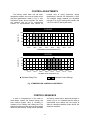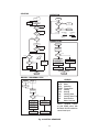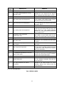
1
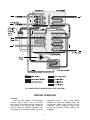
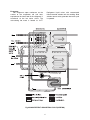
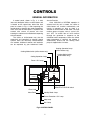
WFC-SC10, 20, 30
WFC-SH10, 20, 30
OPERATING INSTRUCTIONS
WATER FIRED SINGLE-EFFECT
ABSORPTION CHILLER AND CHILLER-HEATER
This product is a water fired absorption unit which provides chilled water for cooling or hot
water for heating in central plant type air conditioning systems. Units with nominal refrigeration
capacities of 10, 20, and 30 tons are complete with operating and safety controls. The
absorption chiller or chiller-heater is energized by a heat medium (hot water) at 158oF to 203oF
from a process, cogeneration, solar or other waste heat source.
When this equipment is applied correctly, installed in accordance with Yazaki
INSTALLATION INSTRUCTIONS and properly maintained, it will provide many years of trouble
free operation.
CONTENTS
GENERAL
•
•
•
ABSORPTION PRINCIPLE
COOLING OPERATION
HEATING OPERATION
2
2
3
CONTROLS
•
•
•
GENERAL INFORMATION
CONTROL ADJUSTMENTS
CONTROL SEQUENCE
5
8
8
OPERATION
•
•
•
•
COOLING
HEATING
REMOTE CONTROL
WINTER SHUTDOWN
Page
Page
10
10
10
10
•
•
SAFETY CONTROLS
PRECAUTIONS
10
10
MAINTENANCE
•
•
•
•
•
•
GENERAL INFORMATION
ROUTINE MAINTENANCE
WINTERIZING
WATER QUALITY
TROUBLESHOOTING GUIDE
ERROR CODES
11
11
11
12
12
13
WARRANTY
•
YAZAKI LIMITED EXPRESS
WARRANTY
15
GENERAL
These instructions are intended to acquaint
the Owner/End User with the operation and
general maintenance requirements of Yazaki
Water Fired Single-Effect Absorption Chiller or
Chiller-Heater units.
Please read ALL instructions carefully and
observe precautions. Failure to operate and
maintain this equipment in accordance with the
OPERATING INSTRUCTIONS may affect the
equipment performace and product Warranty.
If the equipment does not operate as
expected, check the Troubleshooting Guide in
these instructions BEFORE calling your
Authorized Yazaki Service Provider. This
approach will not only save cost but also avoid
any unnecessary downtime.
ABSORPTION PRINCIPLE
Yazaki absorption chillers or chiller-heaters
use a solution of lithium bromide and water,
under a vacuum, as the working fluid. Water is
the refrigerant and lithium bromide is the
absorbent. During cooling operation, refrigerant
liquid boils under the influence of a deep
vacuum in the evaporator and creates a
refrigerating effect which removes heat from the
chilled water circuit. The single-effect absorption
cycle has one generator heated by an external
source of hot water, a condenser, evaporator
and absorber. The absorber and condenser are
water cooled and heat is normally rejected
through a cooling tower.
COOLING OPERATION
Generator
When the heat medium inlet temperature
exceeds 154.4oF (203oF max.) the solution
pump forces dilute lithium bromide solution into
the generator. The solution boils vigorously
under a vacuum and droplets of concentrated
solution are carried with refrigerant vapor to the
primary separator. After separation, refrigerant
vapor flows to the condenser and concentrated
solution is precooled in the heat exchanger
before flowing to the absorber.
in the condenser due to the influence of the
absorber. As refrigerant liquid flows over the
surface of the evaporator coil it boils and
removes heat, equivalent to the latent heat of
the refrigerant, from the chilled water circuit. The
recirculating chilled water is cooled to 44.6oF
and the refrigerant vapor is attracted to the
absorber.
Absorber
A deep vacuum in the absorber is
maintained by the affinity of the concentrated
solution from the generator with the refrigerant
vapor formed in the evaporator. The refrigerant
vapor is absorbed by concentrated lithium
bromide solution flowing across the surface of
the absorber coil. Heat of condensation and
dilution are removed by the cooling water and
rejected through a cooling tower. The resulting
dilute solution is preheated in the heat exchanger
before returning to the generator where the
cycle is repeated.
Condenser
In the condenser, refrigerant vapor is
condensed on the surface of the cooling coil and
latent heat, removed by the cooling water, is
rejected to a cooling tower. Refrigerant liquid
accumulates in the condenser and then passes
through an orifice into the evaporator.
Evaporator
In the evaporator, the refrigerant liquid is
exposed to a substantially deeper vacuum than
2
Fig.1 SINGLE-EFFECT ABSORPTION CYCLE (COOLING)
HEATING OPERATION
Generator
When the heat medium inlet temperature
exceeds 154.4oF (203oF max.) the solution
pump forces dilute lithium bromide solution into
the generator. The solution boils vigorously
under a vacuum to generate refrigerant vapor
and droplets of concentrated solution. Since the
changeover valve is open during heating
operation, the mixture of refrigerant vapor and
concentrated solution flows directly into the
evaporator. Some refrigerant vapor flows
through the condenser before reaching the
evaporator.
3
Evaporator
Hot refrigerant vapor condenses on the
surface of the evaporator coil and heat,
equivalent to the latent heat of the refrigerant, is
transferred to the hot water circuit. The
recirculating hot water is heated to 131oF.
Refrigerant liquid mixes with concentrated
lithium bromide solution and the resulting dilute
solution returns to the generator where the cycle
is repeated.
Fig.2 SINGLE-EFFECT ABSORPTION CYCLE (HEATING)
4
CONTROLS
GENERAL INFORMATION
A control panel, shown in Fig. 3, is built
into each absorption chiller or chiller-heater and
is located on the control box, behind the front
panel as shown in Fig. 4. After inspecting the
control panel or changing the mode of operation,
make sure that the front panel is replaced and
secured with screws to prevent rain from
entering the cabinet and unauthorized tampering
with the controls.
The chiller or chiller-heater may also be
supervised and controlled by external control
systems when the necessary interconnections
are installed. Additional controls and interlocks
can be explained by your Authorized Yazaki
Service Provider.
Once COOLING or HEATING operation is
selected and the unit is started, the chiller or
chiller-heater will function automatically and
remain in operation as long as there is a
demand for chilled water or hot water. The heat
medium pump or bypass valve is cycled ON
and OFF to control flow of heat medium
through the generator in response to the
chilled/hot water temperature. When the chilled
water temperature is satisfied, the solution is
automatically diluted and the cooling water
pump is stopped after 4 minutes.
Heating Operation Lamp
(chiller-heater only)
Cooling Mode Switch (chiller-heater only)
Heating Mode Switch
(chiller-heater only)
Cooling Operation Lamp
Power ON Lamp
COOL
HEAT
POWER
RUN
STOP
STOP
ERROR No.
IF RUN
REMOTE
RUN
PRETIME
RESET
REMOTE-STOP-RUN Switch
Error Code
Alarm Reset
Standby Mode Lamp
Freeze Protection ON Lamp
Stop Lamp
Run Lamp
Fig.3 CONTROL PANEL
5
Chiller or Chiller-Heater
F11
F2
208V
2A
24V
3A
F12
F4
208V
2A
24V
2A
REPLACEMENT
SYMBOL
RATING
FT1, FT2
5A
F11, F12
2A
F4
2A
FT1
F2
208V
5A
FT2
3A
FUSES
TYPE
Fuji Model
FGAO-2 rated
250V AC
Bussmann
Model GLQ-3,
GMQ-3 or
GMQ-32/10
Fuses must be replaced with the same
model and rating. DO NOT USE a
substitute.
208V
5A
Fuse Panel
Fig. 4 LOCATION OF CONTROLS
6
Solution Pump Thermal Overload (THRP)
Fuse Panel (FT1, FT2, F2, F4, F11 and F12)
WFC-TRUL1
MP
THRP
CPU Board
Control Harness
I/O Board
TR-LV
Control Box
SOLUTION PUMP THERMAL
OVERLOAD SETTINGS (A)
MODEL
SYMBOL
208V
WFC-SC10
THRP
0.4
WFC-SH10
WFC-SC20
THRP
0.7
WFC-SH20
WFC-SC30
THRP
2.0
WFC-SH30
Adjustment Screw
Push and release to RESET
Solution Pump Thermal Overload
The 208V, 60Hz, 3 ph. power supply
must be within voltage tolerances of
+10% and -5%.
CAUTION
FOR YOUR SAFETY DO NOT TOUCH ANY
LIVE ELECTRICAL PARTS. ELECTRIC
SHOCK CAN CAUSE INJURY OR DEATH.
Fig. 4 LOCATION OF CONTROLS
7
CONTROL ADJUSTMENTS
The leaving chilled water and hot water
temperature controls are set at the factory to the
Standard Specifications shown in Fig. 5. Your
Authorized Yazaki Service Provider can adjust
the setpoints with the ACT-3 maintenance
checker to accommodate step control on
multiple units or satisfy alternative design
temperatures, however, the differential is fixed.
The standard factory setpoints are adjustable
from 59.9oF to 41.9oF (leaving chilled water) and
122.9oF to 140.9oF (leaving hot water).
COOLING
75
50
25
0
Maximum Limit
Minimum Limit
Capacity (%)
100
40.1
43.7
41.9
47.3
45.5
50.9
49.1
54.5
52.7
58.1
56.3
61.7
59.9
65.3
63.5
67.1
Chilled Water Outlet Temperature ( F)
o
HEATING
50
25
0
Maximum Limit
75
Minimum Limit
Capacity (%)
100
113.9 117.5
121.1
124.7
128.3
131.9
135.5
139.1
115.7
119.3
122.9
126.5
130.1
133.7
137.3
140.9
Hot Water Outlet Temperature (oF)
•
Standard Rating Point
Standard Control Settings
Fig. 5 TEMPERATURE CONTROL ADJUSTMENTS
CONTROL SEQUENCE
A built in microprocessor in the chiller or
chiller-heater controls the external pumps and
heat medium bypass valve (if installed) in
response to the cooling and heating load. The
operating sequence of each pump and the cooling
tower fan after start-up, during normal operation
and after a normal stop or abnormal shutdown is
shown in Fig. 6. It is important that the chiller or
chiller-heater have control over the pumps to
allow for controlled shutdown under normal and
abnormal conditions.
8
START-UP
OPERATION
Normal
Operation
Start
HM Pump
On (Note)
C/H Water
Pump On
C/H
WTR/Pump
OPG
OL
Normal
Abnormal
Stop
Stop
Normal Stop
By Temp Control
Yes
No
C/H
Water
Temp
Yes
C/H
Water
Temp
No
Operation
Stop
Operation
Chilled Water
Temp. Control (Std)
50.9oF
On
WT1
Off
Hot Water
Temp. Control (Std)
126.5oF
On
WT4
o
43.7 F
WFC-SC/SH
Heating
Off
135.5oF
WFC-SH
CLG/HTG
NORMAL STOP
Cooling
Normal Stop
By Temp Control
CW Pump On
CW
Pump
OPG
No
HM Pump Stop
or HM Bypass
Valve Close
Yes
Heating
Continuous Operation
Of C/H Water Pump
Continuous Operation
Of HM Pump (Note)
CW Pump Stop
After Time Delay
HM Pump On
or HM Bypass
Valve Open
Yes
Heating
Cooling
Continuous Operation
Of C/H Water Pump
80.6oF
Cooling
CW
Temp
Low
CLG/HTG
Cooling Water Temp. Control
84.2oF
On
CTF
Off
CLG/HTG
Continuous Operation
Of HM Pump (Note)
No
CTF On
Solution Pump Stop
After Time Delay
Normal
Operation
HM Pump Stop or HM Bypass
Valve Close Immediately
Standby
MANUAL / ABNORMAL STOP
LEGEND
Abnormal
Stop
Manual
Stop
C/H:
WTR:
OPG:
TEMP:
CLG:
HTG:
CW:
CTF:
HM:
OL:
Alarm
HM Pump Stop
or HM Bypass
Valve Close
CLG/HTG
Heating
Cooling
C/H Water Pump Stop
After Time Delay
CW Pump Stop
After Time Delay
C/H Water Pump Stop
Immediately
HM Pump Stop
Immediately (Note)
NOTE: Optional control
of HM PUMP when HM
BYPASS VALVE installed to
control heat input.
CTF Stop
After Time Delay
HM Pump Stop
Immediately (Note)
Solution Pump Stop
After Time Delay
Chilled/Hot
Water
Operating
Temperature
Cooling
Heating
Cooling Water
Cooling Tower Fan
Heat Medium
Motor Overload
HM Pump Stop or HM Bypass
Valve Close Immediately
Fig. 6 CONTROL SEQUENCE
9
OPERATION
COOLING
HEATING
1. Select STOP on the REMOTE-STOP-RUN
switch to stop heating operation. (If currently
operating in the heating mode.)
2. Push COOLING on the control panel to select
cooling mode. (Automatic selection on
chillers.)
3. Select RUN on the REMOTE-STOP-RUN
switch to start cooling operation. (Cooling
operation will commence 30 minutes after
heating operation is stopped.)
1. Select STOP on the REMOTE-STOP-RUN
switch to stop cooling operation. (If currently
operating in the cooling mode.)
2. Push HEATING on the control panel to
select heating mode.
3. Select RUN on the REMOTE-STOP-RUN
switch to start heating operation. (Heating
operation will commence 30 minutes after
cooling operation is stopped.)
WINTER SHUTDOWN
REMOTE CONTROL
Select REMOTE on the REMOTE-STOPRUN switch to allow external controls to start,
stop and select the chiller-heater operating
mode. (When REMOTE is selected the control
panel is disabled.)
If a chiller-heater is only used in the cooling
mode and shutdown for the winter, operate the
chiller-heater for 30 minutes in the heating mode
to dilute the working fluids. Proceed with
winterizing the cooling tower and cooling water
circuit.
SAFETY CONTROLS
PRECAUTIONS
Safety/limit controls monitor critical operating
conditions in the chiller or chiller-heater and
shutdown the unit when abnormal conditions
occur. An Error Code that designates the cause
of the shutdown, shown in Table 2, is displayed
on the control panel. When the abnormal
condition has cleared, push the Alarm Reset to
restart cooling or heating operation. If the chiller
or chiller-heater does not restart, contact your
Authorized Yazaki Service Provider.
1. Ensure that all AUTO-OFF-MANUAL
switches for external pumps and the cooling
tower fan are set in the AUTO position
during normal operation. (The chiller or
chiller-heater is designed to automatically
control the chilled/hot water pump, cooling
water pump, heat medium pump and/or heat
medium bypass valve.)
2. At the beginning of the cooling season clean
and refill the cooling tower with fresh water.
3. During the heating season the cooling tower
and cooling water circuit should be drained
to avoid freezing and scaling in the absorber
and condenser of the chiller/chiller-heater.
4. When two or more absorption chiller-heater
modules are installed in parallel, set all units
for the same operating mode.
10
MAINTENANCE
GENERAL INFORMATION
ALL
MAINTENANCE
SHOULD
BE
PERFORMED BY SKILLED, EXPERIENCED
PERSONNEL. Your Authorized Yazaki Service
Provider can help you establish a standard
maintenance procedure.
For your safety, keep the area around the
equipment clear and free of combustible
materials, gasoline and other flammable
substances. DO NOT obstruct service access to
the equipment.
ROUTINE MAINTENANCE
Routine maintenance should be provided
throughout the life of the equipment to ensure
satisfactory operation and performance.
During the warranty period, an Authorized
Yazaki Service Provider must be engaged to
provide routine maintenance on chillers at the
beginning of each cooling season (spring
changeover) and, on chiller-heaters at the
beginning of each cooling season (spring
changeover)
and
heating
season
(fall
changeover). When the chiller or chiller-heater is
used for process cooling or heavy load operation
it may be necessary to schedule additional
service visits to evacuate noncondensible gases
from the vacuum section. The following routine
maintenance checks and adjustments are
normally performed on the chiller or chillerheater:
5. Measure the inlet and outlet chilled water,
cooling
water
and
heat
medium
temperatures.
6. Check the mounting level of the chiller or
chiller-heater.
7. Measure the power supply voltage in each
phase.
8. Inspect the cooling tower and cooling water
circuit. (Note the condition of the cooling
water and effectiveness of the water
treatment provided.)
9. General inspection of the chiller cabinet and
components.
Fall Changeover
Chiller-Heater)
(Heating
Operation
of
1. Evacuate noncondensible gases when the
evaporator is less than 90oF.
2. Measure and adjust (if necessary) the hot
water and heat medium flow.
3. Check the function of the chilled/hot water
flow switch.
4. Measure all temperatures around the chillerheater (including the inlet and outlet hot
water and heat medium temperatures) and
verify that they are normal.
5. Measure the power supply voltages in each
phase.
6. General inspection of the chiller-heater
cabinet and components
Spring Changeover (Cooling Operation of
Chiller/Chiller-Heater)
1. Evacuate noncondensible gases from the
vacuum section.
2. Measure and adjust (if necessary) the
chilled water, cooling water and heat
medium flows.
3. Check the function of the chilled/hot water
flow switch.
4. Measure the absorption cycle temperatures
and verify that they are normal.
WINTERIZING
When the equipment is located outdoors in
climates subject to freezing, cooling water must
be drained from the chiller/chiller-heater, piping
and cooling tower at the end of the cooling
season. Use glycol of adequate concentration in
the chilled/hot water and heat medium circuits to
prevent freeze damage. The glycol will reduce
the cooling and heating capacity but this may be
offset by increasing the circuit flow. If in doubt
about potential freeze damage in your area,
discuss it with your Authorized Yazaki Service
Provider. Remember, damage to the chiller or
chiller-heater due to freezing is not covered by
the product warranty.
11
WATER QUALITY
It is the Owner/End User’s responsibility to
have the cooling water analyzed and chemically
treated (as often as necessary) so that it
conforms to the limits specified in Table 1. The
CHILLED/
HOT
WATER
HEAT
MEDIUM
COOLING
WATER
MAKE-UP
WATER
6.8 - 8.0
7.0 - 8.0
6.5 - 8.2
6.8 - 8.0
400
300
800
300
50
30
200
50
Sulfate ion (SO4 ppm)
50
30
200
50
M-alkalinity (CaCO3 ppm)
50
50
100
50
Total hardness (CaCO3 ppm)
70
70
200*
70
Calcium hardness (CaCO3 ppm)
50
50
150
50
Ionic Silica (SiO2 ppm)
30
30
50
30
Total iron (Fe ppm)
1.0
1.0
1.0
0.3
Copper (Cu ppm)
1.0
1.0
0.3
0.1
ND
ND
ND
ND
Ammonium ion (NH4 ppm)
1.0
0.1
1.0
0.1
Residual chlorine (Cl ppm)
0.3
0.1
0.3
0.3
Free carbon dioxide (CO2 ppm)
4.0
0.4
4.0
4.0
ITEM
o
pH (at 77 F)
o
Standard
Conductivity (µS/cm at 77 F)
Reference
water quality in the chilled/hot water, cooling
water, and heat medium circuits shall not
exceed the following limits:
-
Chloride ion (Cl ppm)
2-
2-
Sulfide ion (S ppm)
+
6.0 - 7.0
Ryzner stability index
NOTES:
1. ND (Not Detectable)
2. *Maximum total hardness of make-up water shall not exceed 70 ppm when bleed off is the only
method used to control water quality.
Table 1 WATER QUALITY REQUIREMENTS
TROUBLESHOOTING GUIDE
SYMPTOM: Chiller/chiller-heater does not operate
POSSIBLE CAUSE
Power supply is disconnected
Solution pump overload
relay tripped
Manual reset device is tripped
High heat medium inlet
temperature
Fuse has melted
REMEDY
Check the power ON lamp. If it is OFF check that the main
disconnect is closed and the line fuses are in good condition.
Check for Error Code E08 on the control panel. If this error code is
displayed, first push the manual Reset button on the overload relay
and then push the Alarm Reset on the control panel.
Check the Error Code on the control panel and identify the fault
from Table 2. After the cause is eliminated, push the Alarm Reset.
Check for Error Code E38 on the control panel. If this error code is
displayed, push the Alarm Reset on the control panel after the heat
medium inlet temperature falls below 190.4oF.
Check the condition of each fuse in the control box and replace as
necessary.
12
SYMPTOM: Poor cooling capacity
POSSIBLE CAUSE
Poor vacuum
Low heat medium inlet
temperature
High cooling water inlet
temperature
Low cooling water flow
Fouling in the condenser and
absorber
REMEDY
Evacuate noncondensible gases from the vacuum section through
service valves A and B.
Check the heat medium inlet temperature. Increase the temperature
if it is below the original design conditions (max. 203oF).
Check for Error Code E37 on the control panel. If this error code is
displayed, push the Alarm Reset on the control panel after the cause
is eliminated.
Check for flow restrictions in the strainer and piping.
Measure the temperature difference between the condenser surface
and the cooling water outlet (LTD). If LTD is greater than 7oF, with
a good vacuum and correct cooling water flow, the condenser and
absorber tubes are fouled and should be chemically cleaned.
NOTE: If the chiller or chiller-heater does not operate as expected after checking the above remedies,
contact your Authorized Yazaki Service Provider for further assistance.
ERROR CODES
ERROR
CODE
E01
E02
E03
E04
E05
E06
E07
E08
E09-E12
DESCRIPTION
REMARKS
Remote monitoring system power supply
interrupted
Remote monitoring system communication
wire short circuit or reverse connection
Remote monitoring system communication
line noise
ST2 Interlock open circuit (optional field
wiring connection)
P1 (chilled/hot water pump) overload
relay tripped
P2 (cooling water pump) overload
relay tripped
CT (cooling tower fan) overload
relay tripped
SP (solution pump) overload relay tripped
NA
E13
WTO (chilled/hot water temperature sensor)
wire open or short circuit
E14-E26
NA
E27
FS1 (chilled/hot water flow switch)
low flow
E28
FS2 (cooling water flow switch) low flow
(optional field wiring connection)
13
NA
NA
NA
Immediate shutdown. Manual reset required
after repair.
Immediate shutdown when open circuit
(<14.4oF) or short circuit (>193.6oF) detected.
Automatic reset after repair.
Alarm when low flow is detected for 10 min.
anytime 1 min. after P1 starts. Heat input stops
immediately and restarts automatically
after flow restored. Continuous pump
operation.
Shutdown when low flow is detected for 2 sec.
anytime 1 min. after P2 starts. Automatic reset
after flow restored.
ERROR
CODE
DESCRIPTION
E29-E32
NA
E33
CTI (cooling water temperature sensor)
wire open circuit
E34-E36
NA
REMARKS
Shutdown when open circuit (<14.4oF)
detected for 5 sec. anytime 10 min. after P2
starts. Automatic reset after repair (>39.2oF).
High cooling water inlet temperature
Shutdown when high temp. exceeds 95oF for
5 sec. anytime 3 min. after P2 starts. Manual
reset required after cause eliminated.
E38
High heat medium inlet temperature
Shutdown when high temp. exceeds 204.8oF
for 5 sec. Manual reset required after temp.
falls below 190.4oF.
E39-E42
NA
E37
E43
Low cooling water inlet temperature
Alarm and operation changed to standby
mode when low cooling water inlet temp. falls
below 46.4oF for 2 min. Cooling operation
restarted and alarm automatically reset when
temp. exceeds 48.2oF.
E44
Changeover valve malfunction
(chiller-heater only)
Shutdown when changeover valve does not
open (HON) or close (CON) within 22 sec.
Manual reset required after cause eliminated.
E45-E46
NA
E47
HWT (heat medium temperature sensor)
wire short circuit
Shutdown when short circuit (>239.0oF)
detected for 5 sec. Automatic reset after repair
(<230.0oF).
E48
P3 (heat medium pump) overload
relay tripped
Immediate shutdown. Manual reset required
after repair.
E49
High evaporator temperature
Shutdown when evaporator temp. exceeds
68oF for 20 min. and heat medium inlet temp.
is greater than 140oF. Manual reset required
after cause eliminated.
E50-E71
NA
E72
LT (evaporator temperature sensor) wire
open or short circuit
E73-E92
NA
E93
Model setting error
Shutdown when incorrect settings of DS1 &
DS3 are detected. Automatic reset after the
cause eliminated.
E94
TS1 switch incorrectly set in BC or
VC position
Shutdown after 30 min. when TS1 is not
returned to the central position for normal
operation. Manual reset required after the
cause eliminated.
E95
Data error
Immediate shutdown when open circuit
(<14.4oF) or short circuit (>193.6oF) detected.
Manual reset required after repair.
NOTE: NA (Not Applicable)
Table 2 ERROR CODES
14
WARRANTY
YAZAKI LIMITED EXPRESS WARRANTY
1.
2.
3.
4.
5.
6.
7.
8.
9.
Scope of Coverage. The Limited Express Warranty of Yazaki Energy Systems, Inc ( Company ) applies to the initial retail
purchaser and assigns ( Customer ) of Yazaki water fired chillers and chiller-heaters ( Product ) installed in the U.S.A., Canada
and Mexico.
General Express Warranties.
(a) The Company warrants to the Customer, that the Product shall be free from defects in materials and workmanship
within a period of one (1) year ( Original Warranty Period ) from the time when the Product is initially placed in
operation ( Start-Up Date ), or two (2) years from the date of manufacture, whichever expires first, and subject to the
disclaimers and limitations of this Limited Express Warranty.
(b) For liability under this Limited Express Warranty, the Customer must arrange at its own cost for annual and
seasonal routine maintenance of the Product, prior to cooling operation and prior to heating operating of the Product,
by a Service Provider authorized by the Company, in accordance with the Yazaki Operating and Maintenance
Instructions.
Disclaimer and Limitation of Express Warranties. There are no express warranties other than those contained in this Limited
Express Warranty.
Warranty Registration Card. Every new Product is accompanied by a Warranty Registration Card which must be completed,
signed by an authorized representative of the Customer, and returned to the Company. This Limited Express Warranty shall not
apply unless the Warranty Registration Card is fully completed and returned to the Company within thirty (30) days of the
Start-Up date of the Product.
Warranty Service. All routine maintenance, parts replacement and vacuum section repairs of the Product during the Original
Warranty Period must be performed by a Service Provider authorized by the Company.
Remedy During Original Warranty Period. The Company shall, at its sole discretion, repair or replace the covered Product
or parts thereof which the Company shall determine upon examination to be defective or not in conformity with the Original
Warranty contained herein ( Defective Part ), subject to the terms hereof. The Company shall supply by standard ground
transportation all parts required to repair or replace any Defective Part and shall pay to the Service Provider the necessary labor
charges as fixed in the Company’s warranty service payment schedule in effect from time to time ( Fixed Labor Charges ). The
Customer shall be solely responsible for all labor costs or charges in excess of the Fixed Labor Charges.
Limitation of Warranty and Limitation of Remedy. Customer’s remedies shall be limited (even in the event of the Company’s
default of its warranty obligations or the failure of the essential purposes of this Warranty) exclusively to those provided in
Section 6. UNDER NO CIRCUMSTANCES SHALL THE COMPANY BE LIABLE FOR CONSEQUENTIAL OR INCIDENTAL
DAMAGES. If the limitation of liability fails the essential purpose, the Company’s liability shall be expanded to the minimum
extent to avoid failure of the essential purpose. Customer waives any cause of action or theory of liability including, but not limited to, those arising under contract, tort, strict liability, product liability, statutes, or otherwise except as specifically provided by
the Uniform Commercial Code as modified and limited herein. The warranty periods of all replacement parts and Products shall
be deemed to commence on the Start-Up Date of the original component or Product, not the installation date of the
replacement part or Product, and the Company’s warranty obligation hereunder shall not be extended because of such
replacement.
Disclaimer of Implied Warranties. The Company DISCLAIMS ALL IMPLIED WARRANTIES (OTHER THAN GOOD TITLE)
INCLUDING BUT NOT LIMITED TO THOSE OF FITNESS FOR A PARTICULAR PURPOSE, MERCHANTABILITY, AND
NON-INFRINGEMENT. There are no warranties which extend beyond those express warranties contained in this Limited
Express Warranty. Customer affirms that it has not relied upon the Company’s skill nor judgement to select or furnish Product
for any particular purpose. The Company does not warrant that the Product complies with the requirements of any safety or
environmental code or regulation of any federal, state, municipality or other jurisdiction beyond the specific express warranties
in this Limited Express Warranty.
Specific Exclusions. In addition to all other exclusions contained in this Limited Express Warranty, the Company’s warranty
shall also not apply under the following circumstances:
(a) Damage to the Product caused by an unauthorized Service Provider;
(b) Defect in any part which is not supplied by the Company;
(c) Installation or operation of the Product in any way not described in the applicable Yazaki Installation and Operating
Instructions;
(d) Applications for process cooling (except single-effect absorption chillers);
(e) Failure to provide routine maintenance of the Product by a Company authorized Service Provider in accordance with
the applicable Yazaki Operating and Maintenance Instructions;
(f) Failure to maintain the quality, flow and supply temperature of cooling water in accordance with Yazaki standards and
limitations;
(g) Damage caused to the Product from freezing, overpressure and corrosion in any water circuit;
(h) Misuse, abuse, negligence, accident, natural disaster, alteration, misapplication or experimental use of the Product;
(i) Normal fading and minor deterioration of the cabinet surface caused by exposure to the elements;
(j) Removal of the Product from its original installation site unless the relocation is approved in writing by the Company
and performed by a Company authorized Service Provider;
(k) Materials, such as inhibitor and batteries (if required), that are consumed during normal operation of the Product;
(l) Damage to other products outside the Product, not supplied by the Company, caused by use of materials that are not
compatible with the operating temperatures of the Product, regardless of the absence of specific instructions in Yazaki
Installation and Operating Instructions.
15
AUTHORIZED YAZAKI SERVICE PROVIDER
For information concerning service, operation
or technical assistance, please contact your
Authorized Yazaki Service Provider or the following:
YAZAKI ENERGY SYSTEMS, INC.
701 E. PLANO PARKWAY, SUITE 305, PLANO, TEXAS
75074-6700
Phone: 469-229-5443
Fax: 469-229-5448
Email: [email protected]
Web: www.yazakienergy.com
This symbol on the product’s nameplate
means it is listed by
UNDERWRITERS LABORATORIES, INC.
Yazaki reserves the right to discontinue, or change at any time,
specifications or designs without notice and without incurring obligations.
OP-WFCS-0507
16