1
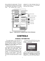
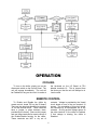
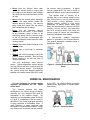
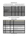
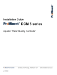
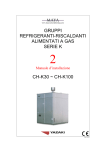
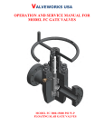
WFC-SC5 OPERATING INSTRUCTIONS GAS FIRED SINGLE-EFFECT ABSORPTION CHILLER This product is a water-fired absorption unit which provides chilled water for cooling in central plant type air conditioning systems. The unit has a nominal capacity of 5 tons and is complete with operating and safety controls. The unit is energized by heat medium (hot water) from a process, cogeneration, solar, or other waste heat applications that can supply the heat medium fluid within the operating range of 158 – 203°F (70 – 95°C). When this equipment is correctly applied, installed in accordance with Yazaki INSTALLATION INSTRUCTIONS, and properly maintained, it can provide many years of trouble-free operation. CONTENTS GENERAL ABSORPTION PRINCIPLE COOLING OPERATION Page 2 2 CONTROLS GENERAL INFORMATION CONTROL ADJUSTMENTS CONTROL SEQUENCE 3 4 4 OPERATION COOLING REMOTE CONTROL SAFETY CONTROLS PRECAUTIONS 5 5 6 6 MAINTENANCE GENERAL INFORMATION ROUTINE MAINTENANCE MAINTENANCE INTERVALS EVACUATION OVERVIEW CHEMICAL MAINTENANCE WINTER SHUTDOWN TROUBLESHOOTING WATER QUALITY ERROR CODES Page 7 7 7 7 8 9 9 10 10 WARRANTY YAZAKI LIMITED EXPRESS WARRANTY 11 GENERAL These instructions are intended to acquaint the Owner/End User with the operation and general maintenance requirements of Yazaki WFC-SC5 WaterFired Single-Effect Absorption Chiller units. affect the equipment product Warranty. performance and If the equipment does not operate as expected, check the Troubleshooting Guide in these instructions BEFORE calling your Yazaki Authorized Service Provider (ASP). This approach will not only save cost but also avoid any unnecessary downtime. Please read ALL instructions carefully and observe precautions. Failure to operate and maintain this equipment in accordance with the OPERATING INSTRUCTIONS may ABSORPTION PRINCIPLE Yazaki absorption chillers use a solution of lithium bromide and water, under a vacuum, as the working fluid. Water is the refrigerant and lithium bromide is the absorbent. The single-effect absorption cycle has one generator heated by an external source of hot water, a condenser, an evaporator and an absorber. The absorber and condenser are water cooled and heat is normally rejected to a cooling tower. During cooling operation, refrigerant liquid boils under the influence of a deep vacuum in the evaporator and creates a refrigeration effect which removes heat from the chilled water circuit. COOLING OPERATION Generator Evaporator When the heat medium inlet temperature exceeds 154.4°F (68°C), with a maximum of 203°F (95°C), the solution pump forces dilute solution into the generator. The solution is dripped over the generator tubing bundle where it boils under vacuum, releasing refrigerant vapor. The hot refrigerant vapor flows into the condenser and concentrated solution drips into the generator sump where it drains down and flows through a heat exchanger before flowing to the absorber. In the evaporator, refrigerant liquid is exposed to a substantially deeper vacuum than in the condenser due to the influence of the absorber. As refrigerant liquid flows over the surface of the evaporator tubing bundle, it boils and removes from the chilled water circuit an amount of heat equivalent to the latent heat of the refrigerant. The recirculating chilled water is cooled to 44.6°F (7°C) while the refrigerant vapor is attracted to the concentrated solution dripping over the absorber tubing bundle. Condenser Absorber In the condenser, refrigerant vapor is condensed on the surface of the condenser tubing bundle and latent heat, removed by the cooling water, is rejected to a cooling tower. Refrigerant liquid accumulates in the condenser and then passes through an orifice into the evaporator. A deep vacuum in the absorber is maintained by the affinity of the concentrated solution from the generator with the refrigerant vapor formed in the evaporator. Refrigerant vapor is absorbed by concentrated lithium bromide solution flowing across the surface of the absorber coil and 2 being cooled by the cooling water. The heat of condensation and dilution are removed by the cooling water and rejected to a cooling tower. The resulting dilute solution is preheated in a heat exchanger before the solution pump returns it to the generator where the cycle is repeated. Dilute Solution Concentrated Solution Refrigerant Vapor Refrigerant Liquid Heat Medium Chilled Water Cooling Water Figure 1 – SINGLE-EFFECT ABSORPTION CYCLE (COOLING) CONTROLS GENERAL INFORMATION The control panel of the WFC-SC5 is located behind the front panel of the unit. A non-fused breaker is present on the control panel for disconnect purposes. It does not substitute for any other NEC-required disconnects external of the unit. All control of the WFC-SC5 unit is done through a touch-screen device which is included with the chiller. Also on the front of the control panel is a small window which allows observation of three LEDs on the control boards. These LEDs are labeled “CHD”, “CHE”, and “PL”. The CHD LED illuminates when the unit is Enabled. The CHE LED illuminates when the unit is in alarm condition. The PL LED illuminates any time there is power to the unit and the on-board disconnect is turned on. The root screen of the GT01R device allows for status monitoring, I/O monitoring, changes to the operation of the unit, and data history. Full operating details are available in the WFC-SC5 Service Manual. 3 CONTROL ADJUSTMENTS value, use the “Δ” button to return to the root menu. In order to set the desired leaving chilled water temperature, press “MANUAL OPERATION”, then press the “>” button three times to get to the “PARAMETER SET” screen. Then simply use the “▲” and “▼” buttons to change the set point to the desired value. Once set to the desired The set point itself can be set as low as 41.9°F (5.5°C) and as high as 59.9°F (15.5°C), but the dead band will always be 7.2°F (4°C). The dead band cannot be adjusted. CONTROL SEQUENCE A built-in microprocessor in the chiller controls the external pumps in response to the cooling load. The operating sequence of each pump and the cooling tower fan after startup, during normal operation, and after a normal stop is shown below in a series of flow charts. It is important that the chiller has control over the pumps to allow for controlled shutdown under normal and abnormal circumstances. 4 OPERATION COOLING To turn on the chiller, simply turn on the disconnect switch on the Control Panel. The unit will engage immediately. The unit will be Enabled so long as the circuit is made at the terminals on the I/O Board at TB1 labeled terminals 10. This is jumped from the factory so that the unit will always be in Local control. REMOTE CONTROL To Enable and Disable the chiller by remote control, locate TB1 on the I/O board. There are two terminals identified as terminal 10 on this terminal block. These terminals have a jumper in place between them, provided by the factory. Remove this jumper and use these terminals for remote control of the Enable/Disable function for the chiller. These terminals are NOT a dry set of contacts. Voltage is provided by the Yazaki circuit board on one of the two terminal 10 screws. The completion of this circuit would be controlled by a field-supplied set of dry contacts. So long as that voltage returns to the other terminal 10, the chiller is Enabled. If that voltage is missing, the chiller is Disabled. 5 SAFETY CONTROLS Safety and limit controls monitor critical operating conditions in the chiller and may shutdown the unit when abnormal conditions occur. An Error Code will be displayed on the touch screen control. To view the code, from the root screen, press “STATUS MONITOR”. The following screen should then be displayed. When errors are cleared, they are recorded in the Error History screen. The last 6 errors are kept in memory, even after the unit has had power to it disconnected. To access this error history, from the root screen, press “DATA HISTORY”. Press the “>” button, located at the top right corner of the screen, until the screen shown below is reached. Refer to Table 2 in this manual, or to the Service Manual, for explanation of the “ERROR” displayed. This screen displays the last 6 error codes. Pressing the “CLR” button will clear these codes from memory. For an explanation of code numbers found on this screen, refer to Table 2 in this manual or to the Service Manual. Press the “Δ” button, located at the top left of the screen, to return to the root screen. Many errors automatically clear themselves when the abnormal condition no longer exists. However, some errors do require a manual reset of the unit. To reset the unit, turn off the breaker on the control panel, wait 10 seconds, then turn the breaker back on. PRECAUTIONS Ensure that all AUTO-OFF-HAND switches for external pumps and the cooling tower fan are set in the AUTO position during normal operation. The chiller is designed to automatically control the chilled water pump, cooling water pump, heat medium pump and/or heat medium bypass valve. 1. At the beginning of the cooling season clean and refill the cooling tower with fresh water. 2. During the winter season the cooling tower and cooling water circuits should be drained to avoid freezing. 3. When two or more absorption chiller modules are installed in parallel, set all units for the same operating mode. 6 MAINTENANCE GENERAL INFORMATION ALL MAINTENANCE SHOULD BE PERFORMED BY TRAINED AND EXPERIENCED PERSONNEL. Your Yazaki Authorized Service Provider (ASP) can help you establish a standard maintenance procedure. For your safety, keep the area around the equipment clear and free of combustible materials, gasoline and other flammable substances. DO NOT obstruct service access to the equipment. ROUTINE MAINTENANCE Routine maintenance should be provided throughout the life of the equipment to ensure satisfactory performance and operation. on chillers at the beginning of each cooling season. When the chiller is used for process cooling or heavy load operation it may be necessary to schedule additional service visits to evacuate non-condensable gases from the vacuum section. During the warranty period, an ASP must be engaged to provide routine maintenance MAINTENANCE INTERVALS Every 4 months: Every 12 months: 1. 1. 2. 2. Evacuate non-condensable gases from the vacuum section. Evacuation can be skipped during the off season. Inspect the condition of the cooling tower and cooling water circuit. 3. 4. Check function of the flow switch. Measure the absorption cycle temperatures to verify they remain in normal ranges. Visual inspection of all controls and of the physical condition of the unit. Verify the unit remains level. EVACUATION OVERVIEW Arguably the most important aspect of maintenance for the chiller is maintaining a proper level of vacuum. Evacuation is performed at the front of the machine. The evacuation service valves are referred to as Service Valve A (upper) and Service Valve B (lower). torque wrench (P/N N7510) specifically for use with this service valve. A number of precautions should be observed at all times during evacuation. Key points are: *** Great care must be taken to ensure that no oil enters the Yazaki chiller! Permanent damage could result from even a small amount of oil being introduced into the vacuum section! *** The evacuation service valves are backseating access valves similar to those used throughout the refrigeration industry. The stem has a 10mm square head. The stem secures a copper seal to a steel seat inside the valve. Do not over-torque this valve or else the seal can become damaged and compromise vacuum integrity. The proper torque is 14.75 ft-lbs (20 Nm). Yazaki offers a Never leave a vacuum pump running unattended. Power loss could allow the chiller vacuum section to suck oil out of the pump in a matter of seconds. 7 Never have the Service Valve open unless the vacuum pump is running and the integrity of the vacuum lines between the valve and the pump has been verified as tight. the vacuum level is adequate. A digital vacuum gauge MUST be used in order to determine the true level of vacuum achieved. The desired level of vacuum on a machine that is not running would be less than 1500 microns (<1.5mmHg), with less than 1000 microns (<1mmHg) preferred. On a machine actively running in Cool mode (attempting to satisfy chilled water loop load), the desired level of vacuum is 4-5000 microns (4-5mmHg), no less. Any lower than that on a running machine can cause the vacuum pump to remove an extraordinary amount of refrigerant vapor (water). Never have the vacuum pump discharge tube in the water bucket unless the vacuum pump is running. The vacuum pump could suck water from the bucket and contaminate the oil charge. Never pull an extended vacuum (exceeding a few hours). If such seems to be necessary, there is likely to be something wrong with the vacuum pump or the oil has been contaminated with moisture inherently found inside the chiller vacuum section. A step-by-step, detailed evacuation method is provided in the Service Manual. The general evacuation assembly setup is displayed in Figure 3. Always start with a fresh oil charge in the vacuum pump. Always use a liquid trap or collection flask. Always use a vacuum gauge to verify the level of vacuum achieved. Run time has almost nothing to do with the level of vacuum achieved. Use only dual-stage, deep vacuum pumps. Typical refrigeration vacuum pumps may not perform well on a vessel as large as the chiller’s vacuum section. Just because the vacuum pump has stopped producing bubbles in the water bucket does NOT mean Figure 3 – General Evacuation Assembly Setup CHEMICAL MAINTENANCE It is not necessary to perform regular chemical maintenance on the Yazaki chiller itself. by the ASP. An inhibitor charge is typically needed every eight years in Yazaki waterfired chillers. The chemical balance has been established in the factory during run testing. Normally, the only chemical that must be maintained is the inhibitor charge. By capturing non-condensable gases, as shown in Figure 4, comparisons can be made to determine if the normal hydrogen byproduct is being produced at anticipated rates. If more hydrogen is being produced than anticipated, a maintenance inhibitor charge may need to be introduced into the machine Figure 4 – Capturing Gases 8 WINTER SHUTDOWN The fluids contained within the chiller itself need no preparation for freezing conditions. Only the fluid in the chilled water, cooling water, and heat medium fluid circuits needs to be addressed during potentially freezing conditions. breaker on the unit control panel. Then drain each fluid circuit. Once drained, make sure to blow in both directions through each circuit with compressed air (or similar) to make sure no significant amount of liquid remains inside them. If a chiller is to be shut down for the winter, but no fluid circuits are to be drained, then simply Disable the chiller and allow the unit to complete its Post Dilution Cycle. Once completed, it is safe to leave the unit as it sits for the off season. Make certain that appropriate measures are taken to ensure the fluids in all fluid circuits are protected from freezing (glycol, heat tape, etc.). When the equipment is located outdoors in climates subject to freezing, cooling water should be drained from the chiller, fluid circuit piping, and cooling tower at the end of the cooling season. Use glycol of adequate concentration in the chilled water and heat medium circuits to prevent freeze damage. The glycol will reduce the cooling and heating capacity but this may be offset somewhat by increasing the circuit flow. If in doubt about potential freeze damage in your area, discuss it with your ASP. Remember, damage to the chiller due to freezing is not covered by the product warranty. If a chiller is to be shut down and fluid circuits are to be drained, Disable the chiller and allow the unit to complete its Post Dilution Cycle. Once completed, turn off the TROUBLESHOOTING SYMPTOM: Chiller does not operate. Possible Cause No High Voltage Solution Pump Not Running Chiller is not running but WTO temperature is above set point. REMEDY Check the LED for the Power indication on the Control Panel. If it is not illuminated, check the main power disconnect, fuses, and breakers. Check for illumination of the "CHE" LED on the Control Panel. If lit, check the touch screen to determine the current error code. Nothing may be wrong. If the system chilled water loop has satisfied by reaching the desired set point, the unit will shut down until the WTO sensor reads a temperature 7.2°F (4°C) above the set point temperature, no matter how long that may take. To force operation, turn power off to the chiller, leave power off for 10 seconds, then restore power. The chiller should start up if the WTO sensor reading is above the set point. SYMPTOM: Poor cooling capacity. Possible Cause Poor Vacuum High Inlet Cooling Water Temperature Low Cooling Water Flow Rate Condenser/Absorber Fouling, Scale Buildup Everything appears normal but the leaving chilled water temperature is too high. REMEDY Evacuate the machine per normal maintenance procedure. Check the cooling tower fan. Check the cooling tower fluid level. Check the cooling tower sump and cooling water circuit strainers. Check the cooling water circuit strainers. It may be necessary to drain the cooling water circuit and open the inspection doors on the chiller condenser and absorber for a visual confirmation. Nothing may be wrong. If the load of the chilled water circuit exceeds the capacity of the chiller, the system will find equilibrium at a higher leaving chilled water temperature. If the temperature drop through the chilled water loop is approximately 8-12°F (4-6°C), then the chiller is actually giving its full capacity and it simply may not be enough. Check for reasons that the load may have artificially increased (open doors, new equipment, leaking valves, etc.) 9 WATER QUALITY It is the End User’s responsibility to have the cooling water analyzed and chemically treated as often as necessary so that it conforms to the CHILLED WATER 6.8 - 8.0 HEAT MEDIUM COOLING WATER 7.0 – 8.0 6.5 - 8.2 MAKE-UP WATER 6.8 - 8.0 Conductivity (S/cm at 77°F) 400 300 800 300 Chloride ion (Cl- ppm) 50 30 200 50 ITEM Standard pH (at 77°F) Reference limits specified in Table 1. The water quality in the chilled water, cooling water, and heat medium circuits shall not exceed the following limits: Sulfate ion (SO42- 50 30 200 50 M-alkalinity (CaCO3 ppm) ppm) 50 50 100 50 Total hardness (CaCO3 ppm) 70 70 200* 70 Calcium hardness (CaCO3 ppm) 50 50 150 50 Ionic silica (SiO2 ppm) 30 30 50 30 Total iron (Fe ppm) 1.0 1.0 1.0 0.3 Copper (Cu ppm) 1.0 1.0 0.3 0.1 Sulfide ion (S2- ppm) ND ND ND ND Ammonium ion (NH4+ ppm) 1.0 0.1 1.0 0.1 Residual chlorine (Cl ppm) 0.3 0.1 0.3 0.3 Free carbon dioxide (CO2 ppm) 4.0 0.4 4.0 4.0 - - 6.0 - 7.0 - Ryzner stability index NOTES: 1. ND (Not Detectable) 2. *Total hardness of make-up water shall not exceed 70 ppm when bleed off is the only method used to control water quality. Table 1 – WATER QUALITY REQUIREMENTS ERROR CODES Error Code E05 E06 E07 E08 E13 E27 E33 E37 Error Description P1 Error P2 Error CTF Error Solution Pump Error WTO Sensor Error Flow Switch 1 Open CTI Sensor Error High Cooling Water Temperature Error Display on Touch Screen P1 ERR P2 ERR CTF ERR SP ERR WT SENSOR FS1 ERR CTI SENSOR CTI HIGH E38 Heat Medium Overtemp Error HWT HIGH E43 Low Cooling Water Temperature Error CTI LOW E47 E48 E49 E72 HWT Sensor Error P3 Error High Evaporator Temperature LT Sensor Error HWT SENSOR P3 ERROR COOLING LT SENSOR Remarks P1D circuit is open. P2D circuit is open. FD circuit is open. Solution Pump VFD controller reports alarm condition. WTO sensor reads below 14°F (-10 °C) or above 194°F (90°C). On-board chilled water flow switch is open. CTI sensor reads below 14°F (-10 °C) or above 194°F (90°C). CTI sensor reads above 95°F (35°C) for 5 continous seconds. Ignored for first 3 minutes of a cycle. HWT sensor reads above 204.8°F (96°C) for 5 consecutive seconds. Reset only allowed once HWT sensor reading falls below 190.4°F (88°C). CTI sensor reads below 46.4°F (8 °C) for more than 2 consecutive minutes. Reset only allowed once CTI sensor reads above 48.2°F (9°C). HWT sensor reads above 212°F (100°C). P3D circuit is open. LT sensor reads above 68°F (20°C) while HWT sensor reads above 140°F (60°C) for 20 consecutive minutes. LT sensor reads below 14°F (-10 °C) or above 194°F (90°C). Table 2 - ERROR CODES 10 WARRANTY expanded to the minimum extent to avoid failure of the essential purpose. Customer waives any cause of action or theory of liability including, but not limited to, those arising under contract, tort, strict liability, product liability, statutes, or otherwise except as specifically provided by the Uniform Commercial Code as modified and limited herein. The warranty periods of all replacement parts and Products shall be deemed to commence on the Start-Up Date of the original component or Product, not the installation date of the replacement part or Product, and the Company’s warranty obligation hereunder shall not be extended because of such replacement. 8. Disclaimer of Implied Warranties. The Company DISCLAIMS ALL IMPLIED WARRANTIES (OTHER THAN GOOD TITLE) INCLUDING BUT NOT LIMITED TO THOSE OF FITNESS FOR A PARTICULAR PURPOSE, MERCHANTABILITY, AND NON-INFRINGEMENT. There are no warranties which extend beyond those express warranties contained in this Limited Express Warranty. Customer affirms that it has not relied upon the Company’s skill nor judgement to select or furnish Product for any particular purpose. The Company does not warrant that the Product complies with the requirements of any safety or environmental code or regulation of any federal, state, municipality or other jurisdiction beyond the specific express warranties in this Limited Express Warranty. 9. Specific Exclusions. In addition to all other exclusions contained in this Limited Express Warranty, the Company’s warranty shall also not apply under the following circumstances: (a) Damage to the Product caused by an unauthorized Service Provider; (b) Defect in any part which is not supplied by the Company; (c) Installation or operation of the Product in any way not described in the applicable Yazaki Installation and Operating Instructions; (d) Applications for process cooling (except single-effect absorption chillers); (e) Failure to provide routine maintenance of the Product by a Company authorized Service Provider in accordance with the applicable Yazaki Operating and Maintenance Instructions; (f) Failure to maintain the quality, flow and supply temperature of cooling water in accordance with Yazaki standards and limitations; (g) Damage caused to the Product from freezing, overpressure and corrosion in any water circuit; (h) Misuse, abuse, negligence, accident, natural disaster, alteration, misapplication or experimental use of the Product; (i) Normal fading and minor deterioration of the cabinet surface caused by exposure to the elements; (j) Removal of the Product from its original installation site unless the relocation is approved in writing by the Company and performed by a Company authorized Service Provider; (k) Materials, such as inhibitor and batteries (if required), that are consumed during normal operation of the Product; (l) Damage to other products outside the Product, not supplied by the Company, caused by use of materials that are not compatible with the operating temperatures of the Product, regardless of the absence of specific instructions in Yazaki Installation and Operating Instructions. YAZAKI LIMITED EXPRESS WARRANTY 1. Scope of Coverage. The Limited Express Warranty of Yazaki Energy Systems, Inc (“Company”) applies to the initial retail purchaser and assigns (“Customer”) of Yazaki water fired chillers and chillers (“Product”) installed in the U.S.A., Canada and Mexico. 2. General Express Warranties. (a) The Company warrants to the Customer, that the Product shall be free from defects in materials and workmanship within a period of one (1) year (“Original Warranty Period”) from the time when the Product is initially placed in operation (“Start-Up Date”), or two (2) years from the date of manufacture, whichever expires first, and subject to the disclaimers and limitations of this Limited Express Warranty. (b) For liability under this Limited Express Warranty, the Customer must arrange at its own cost for annual and seasonal routine maintenance of the Product, prior to cooling operation and prior to heating operating of the Product, by a Service Provider authorized by the Company, in accordance with the Yazaki Operating and Maintenance Instructions. 3. Disclaimer and Limitation of Express Warranties. There are no express warranties other than those contained in this Limited Express Warranty. 4. Warranty Registration Card. Every new Product is accompanied by a Warranty Registration Card which must be completed, signed by an authorized representative of the Customer, and returned to the Company. This Limited Express Warranty shall not apply unless the Warranty Registration Card is fully completed and returned to the Company within thirty (30) days of the Start-Up date of the Product. 5. Warranty Service. All routine maintenance, parts replacement and vacuum section repairs of the Product during the Original Warranty Period must be performed by a Service Provider authorized by the Company. 6. Remedy During Original Warranty Period. The Company shall, at its sole discretion, repair or replace the covered Product or parts thereof which the Company shall determine upon examination to be defective or not in conformity with the Original Warranty contained herein (“Defective Part”), subject to the terms hereof. The Company shall supply by standard ground transportation all parts required to repair or replace any Defective Part and shall pay to the Service Provider the necessary labor charges as fixed in the Company’s warranty service payment schedule in effect from time to time (“Fixed Labor Charges”). The Customer shall be solely responsible for all labor costs or charges in excess of the Fixed Labor Charges. 7. Limitation of Warranty and Limitation of Remedy. Customer’s remedies shall be limited (even in the event of the Company’s default of its warranty obligations or the failure of the essential purposes of this Warranty) exclusively to those provided in Section 6. UNDER NO CIRCUMSTANCES SHALL THE COMPANY BE LIABLE FOR CONSEQUENTIAL OR INCIDENTAL DAMAGES. If the limitation of liability fails the essential purpose, the Company’s liability shall be 11 YAZAKI AUTHORIZED SERVICE PROVIDER For information concerning service, operation or technical assistance, please contact your Yazaki Authorized Service Provider or the following: YAZAKI ENERGY SYSTEMS, INC. 701 E PLANO PKWY, SUITE 305 PLANO, TEXAS 75074-6700 Phone: 469-229-5443 Fax: 469-229-5448 Email: [email protected] Web: http://www.yazakienergy.com This symbol on the product’s name plate means it is listed by UNDERWRITERS LABORATORIES, INC. Yazaki reserves the right to discontinue, or change at any time, specifications or designs without notice and without incurring obligations. WFC5UL-OI-1A1-0611 12