1
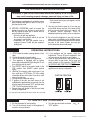
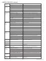
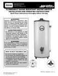
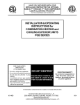
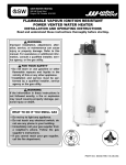
OPERATING, INSTALLATION AND SERVICE MANUAL
COMMERCIAL GAS WATER HEATER
WITH FLUE DAMPER AND ELECTRIC
IGNITION SYSTEM WITHOUT FAN MOTOR
REQUIRES 120V A.C. POWER SUPPLY
WARNING: If the information in these instructions is not followed exactly, a fire
or explosion may result causing property damage, personal injury or death.
Do not store or use gasoline or other flammable vapors and liquids in the
vicinity of this or any other appliance.
WHAT TO DO IF YOU SMELL GAS
G Do not try to light any appliance.
G Do not touch any electrical switch; do not use any phone in your
building.
G Immediately call your gas supplier from a neighborʼs phone. Follow the
gas supplierʼs instructions.
G If you cannot reach your gas supplier, call the fire department.
Installation and service must be performed by a qualified installer,
service agency or the gas supplier.
THIS APPLIANCE SHALL NOT BE INSTALLED IN ANY LOCATION WHERE
FLAMMABLE LIQUIDS OR VAPORS ARE LIKELY TO BE PRESENT.
FLAMMABLE VAPORS MAY BE DRAWN TO THIS WATER HEATER FROM OTHER
AREAS OF THE STRUCTURE BY AIR CURRENTS.
CAUTION THIS WATER HEATER SHOULD NOT BE USED TO HEAT A SPA OR HOT TUB
THIS WATER HEATER SHALL NOT BE INSTALLED IN BATHROOMS, BEDROOMS,
OR ANY OCCUPIED ROOM NORMALLY KEPT CLOSED.
WARNING
This water heater is equipped for one type gas only. Check the data plate near the control access panel for the correct gas. DO NOT
USE THIS WATER HEATER WITH ANY GAS OTHER THAN THE ONE LISTED ON THE DATA PLATE. Failure to use the correct gas
can cause problems which can result in DEATH, SERIOUS BODILY INJURY OR PROPERTY DAMAGE. If you have any questions or
doubts consult your gas supplier or gas company. Water heaters for bottled, propane or liquefied petroleum gas (LPG) are different from
natural gas models. A natural gas heater will not function safely on bottled, propane or liquefied petroleum gas (LPG) and no attempt
should be made to convert a heater from natural gas to any other gas. An odorant is added to the gas used by this water heater.
IF YOU HAVE QUESTIONS THAT ARE NOT ANSWERED IN THE MANUAL YOU MAY CALL THE TOLL
FREE NUMBER 800 900-9063 OR CONTACT US BY EMAIL AT: [email protected].
DO NOT CONTACT US BY TELEPHONE OR EMAIL FOR WARRANTY REGISTRATION. YOUR WATER
HEATER SERIAL NUMBER IS ALREADY ON FILE. THE WARRANTY IS ACTIVATED AT THE TIME OF
PURCHASE. KEEP YOUR RECEIPT TO SHOW TO SERVICE PERSON IF SERVICE IS REQUIRED.
150158 Rev. 2 August - 2010
DANGER
Vapors from flammable liquids
will explode and catch fire causing
death or severe burns.
Do not use or store flammable products such
as gasoline solvents or adhesives in the same
room or area near the water heater.
Keep flammable products:
1. far away from heater,
2. in approved containers,
3. tightly closed and
4. out of children’s reach.
Water heater has a main burner and pilot
flame. The pilot flame:
1. is on all the time and
2. will ignite flammable vapors
Vapors:
1. cannot be seen,
2. are heavier than air,
3. go a long way on the floor and
4. can be carried from other rooms to the
pilot flame by air currents.
Installation:
Do not install water heater where flammable products will be stored or used such as a garage,
basement, storage area or utility room unless the main burner and pilot flames are at least 18”
above the floor. This will reduce, but not eliminate, the risk of vapors being ignited by the main
burner or pilot flame.
Read and follow water heater warnings and instructions.
If owners manual is missing, contact the retailer or manufacturer.
DANGER
Water temperature over 125° F can cause severe burns instantly or
death from scalds.
Children, disabled and elderly are at highest risk of being scalded.
See instruction manual before setting temperature at water heater.
Feel water before bathing or showering.
Temperature limiting valves are available, see manual.
TABLE OF CONTENTS
PAGE
DANGER ..................................................................................................................................................................A
CONSUMER RESPONSIBILITIES, PRESSURE BUILD-UP, INSTALLATION INFORMATION .....................1
GENERAL INFORMATION, INSPECT SHIPMENT, INSTALLATION LOCATION,
CLEARANCE/FLOORING.......................................................................................................................................2
CLEARANCES FROM COMBUSTIBLE CONSTRUCTION, PHYSICAL DAMAGE PROTECTION,
COMBUSTION AND VENTILATION AIR.............................................................................................................3
CORROSIVE ATMOSPHERE, WATER DAMAGEIDRAIN PAN, VENTING, DRAFT DIVERTER, VENT
PIPING, DRAFTHOODIDAMPER INSTALLATION.............................................................................................4
FLUE DAMPER, WATER CONNECTIONS, GAS PIPING ...................................................................................5
TYPICAL INSTALLATION......................................................................................................................................6
A
PAGE
150158 Rev. 2 August - 2010
INSTALLATION SAFETY WARNING L.P. UNITS, ANODES, MULTIPLE HEATER INSTALLATION..........7
HYDROGEN GAS, TEMPERATURE AND PRESSURE RELIEF VALVE...........................................................8
ELECTRICAL, FILLING HEATER WITH WATER, INSTALLATION CHECK LIST BEFORE
PUTTING BURNER IN OPERATION.....................................................................................................................9
WIRING DIAGRAM......................................................................................................................................10 & 11
DAMPER OPERATION SEQUENCE/DAMPER OPERATION, NATURAL GAS MODELS,
L.P. (PROPANE, BOTTLED) GAS MODELS, OUT OF FUEL, EXPOSURE TO WATER, ...............................12
INSTRUCTIONS FOR CLEANING TANK, VACATION, COMBINATION SPACE
HEATING/POTABLE HEATING SYSTEM,VENTING SYSTEM INSPECTION, CONDENSATION .............13
BEFORE PLACING HEATER IN OPERATION, OPERATING INSTRUCTIONS, TO TURN OFF
GAS APPLIANCE..........................................................................................................................................14 & 15
THERMOSTAT, WATER TEMPERATURE REGULATION, GAS PRESSURE, EMERGENCY
SHUTDOWN INSTRUCTIONS, TAMPERING, BURNER MAINTENANCE ...................................................16
WATER HEATER SOUNDS, DRAINING THE WATER HEATER, DO NOT USE THIS WATER
HEATER FOR SPAS OR HOT TUBS, SERVICE MUST BE PERFORMED BY QUALIFIED
PEOPLE, COMMON COMPLAINTS - CHECK LIST BEFORE CALLING FOR SERVICE ............................17
COMMON COMPLAINTS - CHECK BEFORE CALLING FOR SERVICE (CONTINUED) ...........................18
REPLACEMENT PARTS LIST ..............................................................................................................................19
REPLACEMENT PARTS ILLUSTRATION ..........................................................................................................20
DIAGRAM COMBINATION SPACE HEATING /POTABLE WATER HEATING SYSTEM.............................21
WARRANTY LIMITATIONS
THE MANUFACTURER OF THIS WATER HEATER WILL NOT BE RESPONSIBLE FOR TANK
FAILURES OR WATER HEATER FAILURES RESULTING FROM ANY OF THE FOLLOWING.
CONDITIONS AND MAY AT IT'S DISCRETION VOID THE WATER HEATER WARRANTY WHEN
THESE CONDITIONS RESULT IN PREMATURE FAILURES OF THE TANK OR COMPONENTS...
1. INSTALLATIONS NOT COMPLYING WITH ALL LOCAL CODES.
2. FAILURES DUE TO UNDERSIZING OF THE WATER HEATER AND SUBSEQUENT EXCESSIVE
BURNER FIRING.
3. BAD WATER CONDITIONS SUCH AS WELL WATER WITH EXCESSIVE MINERAL DEPOSITS.
IT IS THE RESPONSIBILITY OF THE INSTALLER TO TAKE WHAT EVER STEPS ARE
REQUIRED, INCLUDING THE INSTALLATION OF WATER SOFTENERS, TO PREVENT
EXCESSIVE LIME BUILD UP AND SUBSEQUENT METAL FATIGUE DUE TO OVER HEATING
OF THE TANK BOTTOM.
4. FAILURE TO USE THE HAND HOLE CLEANOUT PROVIDED IN THIS WATER HEATER TO
KEEP LIME DEPOSITS IN THE TANK BOTTOM FROM EXCEEDING 2" IN HEIGHT.
5. INSTALLATION OF MULTIPLE HEATERS IN LINE RATHER THAN PARALLEL PER THE
INSTRUCTIONS PROVIDED ON PAGES 7 AND 8 OF THIS MANUAL RESULTING IN EXCESS
FIRING AND/OR EXCESSIVE CONDENSATION OF ONE OR MORE OF THE HEATERS.
6. FAILURE OF THE HEATER OR COMPONENTS AS A RESULT OF IMPROPER VENTING
RESULTING IN NEGATIVE AIR PRESSURE DUE TO IMPROPER LOCATION OR OVERHEAD
FANS.
7. FAILURE OF THE HEATER OR COMPONENTS CAUSED BY CHEMICALS OR SOLVENTS
BEING STORED IN THE IMMEDIATE VICINITY OF THE WATER HEATER.
B
150158 Rev. 2 August - 2010
CONSUMER RESPONSIBILITIES
WARNING
CLOSED WATER SYSTEMS
THIS MANUAL HAS BEEN PREPARED TO ACQUAINT
YOU WITH THE INSTALLATION, OPERATION AND
MAINTENANCE OF YOUR GAS WATER HEATER AND
TO PROVIDE IMPORTANT SAFETY INFORMATION.
If the water supply system contains a check valve, back flow
preventer or water pressure reducing valve you will have closed
water system and the pressure will build up during the water
heating cycle. The temperature and pressure relief valve on the
water heater will leak during the water heating cycle resulting
in loss of energy. To prevent the build up of lime in the T&P
valve and damage to the water heater by pressure surges you
must install an expansion tank on the cold water supply line.
The tank should have a minimum capacity of 3 U.S. gallons.
It requires both T&P valves and expansion tanks for closed
system.
WE URGE YOU TO READ ALL INSTRUCTIONS
THOROUGHLY before attempting installation or operation of
your water heater. Keep these instructions for future reference.
The manufacturer of this water heater will not be liable for any
damages caused by failure to comply with the installation and
operating instructions outlined on the following pages. These
instructions are a guide for the correct installation of your
water heater. If you lack the necessary skills required or have
difficulty following the directions, you should not proceed but
get help from a qualified person for that part of the installation
you do not understand. Your gas-fired water heater is designcertified by CSA International. The installation should
conform with the local code or the authority having
jurisdiction, or in the absence of such, the National Gas Code.
ANSI Z223.1 NFPA 54. A copy of the Code can be purchased
from American Gas Association Order Processing, 400 N.
Capital St. N.W. Washington D.C. 20001 e-mail ordering:
www.aga.org Fax ordering: 866-816-9444. A rating plate
identifying your water heater will be found next to the gas
control valve (thermostat).
WARNING: FAILURE TO PROVIDE AN
EXPANS ION TANK ON THE COLD WATER LINE
ON A CLOS ED S YS TEM MAY VOID THE
WARRANTY ON THE WATER HEATER.
FOR YOUR SAFETY
Do not use or store gasoline or any other flammable vapors, liquids, or
materials in vicinity of this or any other appliance.
FOR YOUR SAFETY - WHAT TO DO IF YOU SMELL GAS
• Do not try to light any
appliance.
• Do not touch any electrical
switch; do not use any phone
in your building.
• Immediately call your gas
supplier from a neighborʼs
phone. Follow the gas
supplierʼs instructions.
• If you cannot reach your gas
supplier, call the fire
department.
WARNING
Improper installation, adjustment, alteration, service or maintenance can
cause injury or property
damage. Refer to this
manual. For assistance
or additional information
consult a qualified installer, service agency or
the gas supplier.
Please complete the following information at the time of installation. This should be retained and presented along
with the warranty in the event a claim is necessary.
MODEL NUMBER:
SERIAL NUMBER:
INSTALLATION ADDRESS:
TYPE:
THIS WATER HEATER HAS BEEN INSTALLED IN ACCORDANCE WITH THESE INSTALLATION
INSTRUCTIONS AND LOCAL CODE REQUIREMENTS ON
Date
INSTALLER:
THIS WATER HEATER MUST BE PROPERLY AND REGULARLY MAINTAINED.
FAILURE TO DO SO WILL VOID THE WARRANTY.
1
150158 Rev. 2 August - 2010
IMPORTANT
This water heater has been designed and manufactured for the
express purpose of heating and storing potable water and space
heating. See page 12 for space heating instructions. Any use
other than this purpose will release the manufacturer from any
liability or warranty claims stemming from the issue of this
product. Consult local authorities.
BEFORE PROCEEDING WITH THE INSTALLATION OF
THIS WATER HEATER, READ AND THOROUGHLY UNDERSTAND THESE INSTALLATION AND OPERATION
INSTRUCTIONS. IF THERE ARE ANY QUESTIONS,
THIS INSTALLATION SHOULD BE PERFORMED BY A
QUALIFIED SERVICE PERSON.
CAUTION
DO NOT STORE OR USE FLAMMABLE LIQUIDS,
VAPORS, OR MATERIALS IN THE VICINITY OF THIS
OR ANY OTHER APPLIANCE.
GENERAL
INSPECT SHIPMENT: Inspect water heater for possible damage. If damaged, notify carrier immediately. Check markings
on rating plate to make certain it corresponds with your application.
INSTALLATION
Location - Select a location accessible to water lines, gas
supply (type identified on the rating plate), an adequate open
drain, and as close as practical to a chimney or gas vent. When
installed, the water heater must be level. To prevent excessive
heat loss through water piping, locate the water heater as close
as practical to the areas of greatest hot water usage. Do not
locate the water heater where lines could be subjected to
freezing temperatures.
Read these instructions thoroughly before proceeding with the
installation of this new gas-fired water heater. If there is any
difficulty understanding all or any part of these instructions, it
is recommended that a qualified service person perform the
installation.
NOTICE: The manufacturer’s warranty does not cover damage
or injury cause by the use of any energy-saving devices (other
than those authorized by the manufacturer) in conjunction with
this water heater. The use of unauthorized energy-saving
devices may decrease the life of the water heater and endanger
life and/or property. The manufacturer will not be held liable
for loss or injury resulting from the use of any unauthorized
device in conjunction with this water heater.
Adequate clearances shall be provided for easy access to
controls by service personnel to enable proper cleaning,
servicing and operation of the water heater. Under no
circumstances is the front of the water heater to be placed in a
position where the burner tray assembly cannot slide out for
removal when servicing.
Clearance/Flooring - If the water heater is installed
directly on carpeting, it must be installed on a metal or wood
panel which extends beyond the full width and depth of the
water heater by at least 3 inches in any direction. If the water
heater is installed in an alcove, the entire floor must be
covered by the panel. A minimum of 24 inches front clearance
shall be provided for inspection and servicing.
This water heater has been equipped for use with one type of
gas only. Compare the information provided on the rating
plate affixed to the front of the water heater, making sure that
the gas stated on the rating plate is the same as the gas to be
used. DO NOT ATTEMPT TO USE THIS WATER HEATER
WITH ANY GAS OTHER THAN THE TYPE LISTED ON
THE RATING PLATE. Do not attempt to convert this water
heater for use with a gas other than the type for which it is
equipped. Failure to use the proper gas can create an unsafe
condition resulting in property damage, bodily injury or death.
Consult local gas supplier or gas company if there are any
questions.
This water heater may be installed in an alcove on combustible
flooring with clearances from combustible materials as shown
in Figures 1 and 2.
CAUTION
The National Fuel Gas Code (ANSI Z223.1 /NFPA 54)
expressly prohibits the following:
For installations in high altitude regions, this water heater
must be ordered from the supplier to the manufacturer’s specifications for that particular altitude. Contact the company
listed on the rating label when ordering high altitude constructed
water heaters.
a) Installation of a water heater in a bathroom, bedroom, or
any occupied room normally kept closed.
b) Installation of a water heater in a garage, unless the unit
is installed so that the burner and ignition devices are at
least eighteen (18) inches above floor level and protected
to avoid damage by moving vehicle. See Figure 3.
For any questions not covered in this booklet, contact your
dealer or write to us at the address shown on the rating plate
affixed to the front of the water heater.
2
150158 Rev. 2 August - 2010
REMEMBER: Flammable vapors may be drawn to
this water heater from other areas of the structure by
air currents.
CLEARANCES FROM
COMBUSTIBLE CONSTRUCTION
D80-125
D80-165
D80-180
D80-199
D100T-199
D100-199
D100-250
D100-270
D100-300
D75-365
D75-399
D80-512
A
B
C
D
24”
24”
24”
24”
24”
18”
18”
18”
18”
24”
24”
18”
2”
2”
2”
2”
2”
2”
2”
2”
4”
2”
2”
4”
6”
6”
6”
6”
6”
6”
6”
6”
6”
6”
6”
6”
6”
6”
6”
6”
6”
6”
6”
6”
6”
6”
6”
6”
NOTE: HEATER SHALL BE LOCATED OR PROTECTED
SO IT IS NOT SUBJECT TO PHYSICAL DAMAGE BY
MOVING VEHICLES OR AREA FLOODING.
FIGURE 3
FIGURE 1
Typical Installation in Residential Garages (IIlustration
copyright by the American Gas Association. Used by
permission of the copyright holder)
FIGURE 2
For installation on combustible flooring, the tank leg thermal
break piece identified as part No. 25 on the replacement parts
illustration must be installed under each leg.
Combustion and Ventilation Air - Provisions must be
made for adequate combustion and ventilation air. Details
outlining proper air supply for various types of installation are
prescribed by the National Fuel Gas Code (ANSI Z-223.1 /
NFPA 54) latest edition. If the water heater is installed in
unconfined space within the building, infiltration air may be
adequate for proper combustion and ventilation. Buildings of
tight construction (weather stripping, caulked, etc.) require
additional air from outdoors.
If the water heater is installed in a confined space (volume is
less than 50 cu. ft. per 1000 BTUH of the total input rating
of all gas appliances in that space), air must be supplied
through two permanent openings. One opening shall be
within 12 inches from the top of the enclosure and one within
12 inches of the bottom. The openings must be protected by
metal louvers or 1/4” min. mesh metal screen. The size of the
openings are as follows:
1. If the openings communicate directly with an additional
room(s) of sufficient volume, each opening shall have a
minimum free area opening of 1 sq. in. per 1000 BTUH of
the total input rating of all gas appliances in the confined
space, but not less than 100 sq. inches.
2. If the openings communicate directly with the outdoors or
through vertical ducts with the outdoors, each opening
shall have a minimum free area of 1 sq. in. per 4000 of the
total rating of all gas appliances in the enclosure.
3
3. If the openings communicate with the outdoors through
horizontal ducts, each opening shall have a minimum free
area of 1 sq. in. per 2000 BTUH of the total rating of all
gas appliances.
150158 Rev. 2 August - 2010
CAUTION
PAN INSTALLATION AND CONSTRUCTION MUST
CONFORM TO LOCAL CODES AND ORDINANCES.
The draft diverter relief opening of the water heater and the
combustion air inlet must be in the same atmospheric
pressure zone. Large exhaust fans in kitchens or other
locations can lower the air pressure inside an enclosure and
interfere with proper operation and venting of the water heater.
In these cases, the water heater should be installed in a separate
room with combustion and ventilation air supplied directly
from outdoors as previously described.
IF NOT INSTALLED AND OPERATED IN ACCORDANCE
WITH THESE INSTRUCTIONS, UNDER NO CIRCUMSTANCES WILL THE MANUFACTURER OF THIS
WATER HEATER BE LIABLE FOR ANY WATER
DAMAGE OR INJURY IN CONNECTION WITH THIS
WATER HEATER.
VENTING
WARNING
Corrosive Atmosphere - Water heater corrosion and
component failure can be caused by the heating and breakdown
of airborne chemical vapors. Spray can propellants, cleaning
solvents, refrigeration and air conditioning refrigerants,
swimming pool chemicals, calcium and sodium chloride,
waxes, and process chemicals are typical compounds which are
potentially corrosive. These materials are corrosive at very low
concentration levels with little or no odor to reveal their
presence.
The installer to check the installation for venting and for
spillage all around the draft hood relief opening after five
minutes of operation the method to check for flue products
spillage should utilize a flame or a match, or candle or smoke
or flame form another source such a cigarrete or grill lighter
wand. The procedure used should be to play the flame or
smoke around the perimeter of the draft hood from the outside.
If spillage is encountered, it would be manifested by smoke
escaping away from the draft hood or by the flame being
extinguisthed while outside of the hood.
Good venting would be indicated by smoke and the flames
being drawn into the draft hood.
Products of this sort must not be stored near the water heater,
nor should air which is brought in contact with the water
heater contain any of these chemicals. Flammable vapors may
be drawn by air currents from other areas of the structure to
this appliance. If necessary, uncontaminated air should be
obtained from remote or outside sources.
Vent Size
Model
Vent Size
D-80-125 AS
5”
D80-165AS, D80-180AS, D80-199AS
6”
D100T-199AS, D100-199AS, D100-250AS, D100-270AS
6”
D100-300AS
7”
D75-365AS, D75-399AS
8”
D80-512AS
10”
THE WARRANTY ON THIS WATER HEATER DOES NOT
COVER DAMAGE CAUSED FROM OPERATION IN A
CORROSIVE ATMOSPHERE.
Water Damage/Drain Pan - The water heater should be
located in an area where leakage of the tank or connections
will not result in damage to the area adjacent to the water
heater or to lower floors of the structure. WHEN SUCH
Models above may also have prefix “N” (LO-NOX).
*Note: Some models are equipped with draft hoods with
removable reducers for use with larger vents. Vents size must
comply with requirements of local codes or in the absence of
local codes with the provisions of National Flue Gas Code
ANSI Z 223.1 / NFPA 54 latest edition.
ALL AMERICAN STANDARD COMMERCIAL WATER
HEATERS BEGINNING MODEL NUMBERS STARTING
WITH A NUMBER OR THE LETTERS N OR D MAY BE
INSTALLED AS REPLACEMENTS WITH VENTING THAT
MET THE EXISTING CODES AT THE TIME OF THE
INSTALLATION OF THE ORIGINAL WATER HEATER.
Draft Diverter - This water heater has been shipped with a
draft diverter for which it was designed with reference to the
horizontal and vertical planes. If removed, the draft diverter
shall be replaced in the same position and secured to the jacket
top by the screws with which it was installed.
Vent Piping - This water heater must be connected to a
masonry chimney or venting system approved by local codes
or ordinances. The vent connector used to attach the draft
diverter outlet to the chimney or approved vent must be of the
same diameter as the draft diverter outlet or larger. For proper
venting in certain installations, a larger vent connector may be
needed. Consult venting tables in National Fuel Gas Code
ANSI Z223.1/NFPA 54 latest or current or local code officials
for proper application in your area.
LOCATIONS CANNOT BE AVOIDED, A SUITABLE
DRAIN PAN MUST BE INSTALLED UNDER THE WATER
HEATER HAVING A LENGTH AND WIDTH AT LEAST 3
INCHES GREATER THAN THE DIAMETER OF THE
WATER HEATER, A MAXIMUM HEIGHT OF 1-3/4
INCHES, AND BE PIPED TO AN OPEN DRAIN. DO NOT
RESTRICT THE FLOW OF COMBUSTION AIR. DRAIN
DRAFTHOOD LOCATION & FLUE
DAMPER INSTALLATION
FIGURE4
4
150158 Rev. 2 August - 2010
top cold water inlet as it may contain a nonmetallic dip tube.
When making these connections, use a good grade of pipe
joint compound. Be familiar with the location of the shut-off
valve in the cold water line feeding the water heater (See
Figure 5). If a valve is not present, one shall be installed as
shown in Figure 5.
CAUTION
Do not turn on electrical power to water heater until flue
damper is installed and the water heater is filled with water.
Better combustion is achieved by avoiding numerous elbows
in the vent piping. Horizontal piping must be sloped upward
at least 1/4 inch per linear foot of length. All connections in
venting system must be securely fastened with sheet metal
screws or other approved method. Check local codes and
ordinances.
Do not install a check valve or other device that would prevent
reverse flow of water (“closed system”) unless required by
local codes. A closed system will result in frequent operation
of the relief valve. Provisions must be made for protection
against thermal expansion in the event of a closed system (See
Page 1). Warranties do not cover pressure bulges and/or
deformities.
Failure to install a proper venting system can result in fire,
injury, or death.
This water heater is capable of delivering high temperature
hot water at any faucet in the system. Care must be taken
whenever using hot water to avoid scalding injury. Certain
appliances require high temperature hot water (such as
dishwashers and automatic clothes washers). In order to
prevent potential scald injury, install an anti-scald tempering
valve in the water system.
Flue Damper - Refer to Figure 4 and follow these
installation instructions:
1. Remove the damper from the accompanying box shipped
within the crate.
2. Locate the collector outlet on top of the water heater. Place
the damper over the collector outlet and rotate as necessary
to a position in which the damper wiring plug can be fully
engaged with the connector on the side of the water heater.
GAS PIPING
Use clean black iron pipe or equivalent material approved by
local codes and ordinances for gas piping. Install a groundjoint-union in the supply line as close to the water heater as
possible. A manual gas shut-off valve should be at least 5 feet
above floor level and readily accessible. A drip leg (consisting
of a pipe tee, 4 inch nipple, and a cap) should be installed as
shown in Figure 5.
3. Remove clip which holds damper vane closed. The damper
will then open by itself.
4. Being certain that the damper vane will travel freely from
the “closed” to “open” position, secure the flue damper to
the jacket top with sheet metal screws.
5. Connect the damper wiring plug to the connector on the
side of the water heater. Note: The plug and connector can
only be engaged one way (polarized).
Make sure the gas supplied to the heater is the same type as
listed on the rating plate. DO NOT ATTEMPT TO USE THIS
WATER HEATER WITH ANY GAS OTHER THAN THE
TYPE LISTED ON THE RATING PLATE.
6. The Lighting/Operating instructions are outlined on Page
13. The damper must be in the open position when the
water heater main burner is operating (the arrow on the
damper plate is in the “up” position when open. Be certain
the arrow is in a visible position when installed.)
Compound used for the connection of all gas piping should be
resistant to the action of liquefied petroleum (L.P.) gases.
Apply pipe dope sparingly to the male threads only. DO NOT
apply pipe dope to the gas valve inlet. Make certain that no
pipe dope has become lodged in the inlet screen of the gas
valve. This will restrict the flow of gas. When attachment of
gas piping to gas valve inlet is made, extreme care must be
taken to prevent pipe dope from entering the gas valve inlet
and to avoid excessive torque to prevent cracking of the gas
valve inlet housing. The suggested maximum torque is 31.5
ft. lbs. The manufacturer of this water heater will not be liable
for any damage or injury caused as a result of a cracked gas
inlet from excessive torque.
Note: Modification to the flue damper or the draft
diverter may result in personal injury, property damage or
death. The flue damper and draft diverter are to be placed
in position and operation exactly as stated in these instructions without modification.
WATER CONNECTIONS
Installation - Refer to Figure 5 for typical installation. Connect the hot and cold water supply to the water heater, hot to
the location market “HOT” and cold to the location marked
“COLD”. Note: If making cold water connection on top,
determine that the dip tube is in place. If sweat connections are
used, sweat tubing to adapter before attaching adapter to the
5
150158 Rev. 2 August - 2010
TYPICAL INSTALLATION
FIGURE 5
6
150158 Rev. 2 August - 2010
MULTIPLE HEATER
INSTALLATION
After completing all gas connections, check each gas connection and fitting for leaks. Use a soap and water solution or
a commercial leak detector fluid. NEVER USE MATCHES
OR OPEN FLAME WHEN CHECKING FOR GAS LEAKS.
INSTALLATION DIAGRAMS
INSTALLATIONS WHERE HEATERS ARE
MANIFOLDED
The water heater and its individual gas shut off valve must be
disconnected from the gas supply piping system during any
pressure testing or that system at test pressures in excess of 1/2
psig (14” W.C.) or 3.5kPa.
All heaters should have approximately the same input rate. To
manifold a high input heater with a low input heater will
result in the lower input heater running excessively. It is
preferable for all heaters to be the same model.
The water heater must be isolated from the gas supply piping
system by closing its individual manual shut-off valve during
any pressure testing of the gas supply piping system at test
pressures equal to or less than 1/2 psig (14”W.C.) or 3.5kPa.
All heaters must be evenly spaced to provide identical number
of turns, length and size of pipes in each manifold. This is
absolutely necessary to insure a balanced condition to all
heaters in the installation.
If the gas valve is subjected to pressure exceeding 1/2 psig, the
damage to the gas valve could result in an extremely hazardous
condition. If this has occurred, the gas valve must be replaced.
Contact your dealer for service. It is recom-mended that all
service work be done by a qualified service agency.
INSTALLATION
Using Back Connect
INSTALLATION SAFETY WARNING
L.P. UNITS
Liquified petroleum (L.P.) gas is heavier than air and will
remain at floor level if there is a leak. Basements, crawl
spaces, closets and areas below ground level will serve as
pockets for accumulation of leaking gas. Before lighting, sniff
at floor level.
IF YOU SMELL GAS, follow applicable instructions on
Front Cover or Page 13. DO NOT OPERATE APPLIANCE
UNTIL LEAKAGE IS CORRECTED.
WARNING
NEVER OPERATE AN EMPTY OR PARTIALLY FILLED
WATER HEATER
ANODES
This water heater is supplied with anode rods designed to
extend tank life and reduce corrosion. Anodes emit a weak flow
of electrical current through the water to protect the tank.
When present in “highly active” water, a “rotten egg” odor
may be produced from the gases from the anodes, mixing with
the water. This is not the fault of the water heater. Chlorination
of the water supply system should minimize this condition.
(Consult your telephone directory for local water treatment
specialists). REMOVAL OF AN ANODE ROD WILL
FIGURE 6
VOID THE WARRANTY.
7
150158 Rev. 2 August - 2010
that no contact is made with any live electrical part. Do not
connect discharge line directly to drain. (Figure 5)
To prevent bodily injury, hazard to life or damage to property,
the relief valve must be allowed to discharge water in the event
of excessive temperature or pressure developing in the water
heater. The function of the temperature and pressure relief
valve is to discharge water in large quantities should
circumstances demand. If the discharge pipe is not directed to
a drain as shown in Figure 5, or other suitable means, the water
flow may cause property damage.
INSTALLATION
Using Top Connect Only
The discharge line:
(1) Must not be smaller than the pipe size of the relief valve,
(2) Must not be plugged or blocked,
(3) Must be of material capable of withstanding 210°F
without distortion,
(4) Must be installed so as to allow complete drainage of both
the temperature and pressure relief valve and discharge line,
(5) Must terminate at an adequate drain (Figure 5)
(6) Must not have any valve between the relief valve and the
end of the discharge line.
Failure to install and maintain a new properly listed
temperature and pressure relief valve will release the
manufacturer from any claim which might result from
excessive temperature or water pressure.
FIGURE 7
WARNING
HYDROGEN GAS
Hydrogen gas can be produced in a hot water system that has
not been used for a long period of time (generally two weeks
or more). HYDROGEN GAS IS EXTREMELY
FLAMMABLE. To prevent the possibility of injury under
these conditions, we recommend the hot water faucet be
opened for several minutes at the kitchen sink before you use
any electrical appliance which is connected to the hot water
system. Do not light a cigarette, cigar or pipe. Do not smoke.
If hydrogen is present, there will probably be an unusual sound
such as air escaping through the faucet as the water begins to
flow. Remember, no smoking or open flame near the faucet at
the time it is opened.
FIGURE 8
WARNING
TEMPERATURE AND
PRESSURE RELIEF VALVE
Do not attempt to operate this water heater with the cold water
inlet valve closed. Manually operate the pressure-temperature
relief valve at least once a year. To prevent water damage,
discharge line must terminate at an adequate drain. Standing
clear of the outlet (discharge water may be hot), lift and release
the lever handle on the pressure-temperature relief valve to
make the valve operate freely.
For protection against excessive pressures and/or temperatures, a temperature and pressure relief valve must be installed
in the opening marked “temperature and pressure relief valve”.
A design certified by a nationally recognized testing laboratory
that maintains periodic inspection of production of listed
equipment or materials, as meeting the requirements for Relief
Valves and Automatic Gas Shut-off devices for Hot Water
Supply Systems, ANSI Z21.22. Pressure rating of the valve
must not exceed the working pressure shown on the rating
plate of the water heater. Relief piping must terminate 6
inches above a floor drain or external to the building. Do not
thread, cap, or plug the end of this discharge line. Be certain
If the temperature and pressure relief valve on the appliance
discharges periodically, this may be due to thermal expansion
in a closed water supply system (see “Pressure Build-Up in
Water System” - Page 1). Contact the water supplier or local
plumbing inspector on how to correct this situation. Do not
plug the temperature and pressure relief valve.
8
150158 Rev. 2 August - 2010
ELECTRICAL
JUNCTION BOX
120 VAC LESS THAN 5 AMPS
When installed, this appliance must be electrically
grounded in accordance with local codes or in the
abscence of local codes, with the National Electrical Code,
ANSI/NFPA NO. 70-Latest Edition and Canadian Electrical
Code CSA #22.2.
Electrical ON-OFF control must be located near heater in
accordance with local code.
CAUTION: Label all wires prior to disconnection when
servicing controls. Wiring errors can cause improper and
dangerous operation.
Verify proper operation after servicing.
Refer to Page 11, Figure 11, for wiring diagram D80-512AS
model, and Refer to Page 10 Figure 10, for wiring diagram
remains models.
FIGURE 9
FILLING HEATER WITH WATER
CAUTION
1. Close the heater drain valve by turning the handle to the
right (clockwise). The drain valve is on the lower front of
heater.
2. Open the cold water supply valve to the heater.
3. To insure complete filling of the tank, allow air to exit by
opening the nearest hot water faucet. Allow water to run
until a constant flow is obtained. This will let air out of the
heater and the piping.
Operating an empty or partially filled heater will
result in damage to the tank.
4. Check all new water piping for leaks. Repair as needed.
5. Unit is ready to be started. Follow lighting instructions on
Page 13.
INSTALLATION CHECK LIST
Before putting burner in operation
K Gas line equipped with shut-off valve, union and drip
This is presented for ease of reference. It is not comprehensive.
All instructions and warnings must be read and adhered to.
K Approved pipe joint compound used.
K Soap and water solution used to check all connections
plate.
leg (Figure 5).
and fittings for possible gas leaks.
K The installer to visually determine that the main
burner flames are burning correctly without lifting,
floating or flashing back and that the air shutters
should be adjusted and locked to a position that results
in correct burner flame pattern (see page 14) after to
turn on water heater.
A. HEATER LOCATION
K Close to area of vent.
K Indoors and protected from freezing temperatures.
K Proper clearance from combustible surfaces observed
and heater not installed directly on carpeted floor.
K Sufficient fresh air supply for proper operation of
heater.
K Air supply free of corrosive elements and flammable
vapors.
K Provisions made to protect area from water damage.
K Sufficient room to service heater.
E. VENTING
K Draft diverter properly installed.
K Vent connector(s) securely fastened together with
screws.
K Vent connector(s) at least 6” from combustible
B. WATER SUPPLY (See WATER PIPING)
K Install cold water inlet valve (Figure 5)
K Heater completely filled with water.
K Water connection tight and free of leaks.
C. RELIEF VALVE
K Install a new Temperature and Pressure Relief Valve
material.
K Check with spill test
F. ELECTRICAL
K 120 VAC supply.
K ON-OFF switch near heater.
K Cove on junction box.
G. DAMPER
K Damper in place on heater flue collector outlet.
K Damper plate has free movement.
properly and discharge line run to open drain.
K Discharge line protected from freezing (Figure 5).
D. GAS SUPPLY
K Gas supply same as the type of gas listed on the rating
9
150158 Rev. 2 August - 2010
FIGURE 10
WIRING DIAGRAM
10
150158 Rev. 2 August - 2010
FIGURE 11
11
150158 Rev. 2 August - 2010
OTHER THAN THE ONE LISTED ON THE RATING
PLATE (Figure 5). Failure to use the correct gas can cause
problems which result in DEATH, SERIOUS BODILY
INJURY, OR PROPERTY DAMAGE. If you have any
DAMPER OPERATION SEQUENCE
questions or doubts consult your gas supplier or gas company.
NATURAL GAS MODELS
LEGEND
DM Damper Motor
F Fuse
TH Thermostat
ES Endswitch
CM Control Module
R Relay Coil
R1 N/C Relay Contact
R2 N/O Relay Contact
SS1 N/C Safety Switch Contact
SS2 N/O Safety Switch Contact
IF YOU SMELL GAS:
1. Open windows.
2. Get all people out of the building.
3. DO NOT light matches.
4. DO NOT touch electrical switches (on or off).
5. Extinguish any open flames.
6. Use an outside phone and immediately call the gas
company and the fire department. Ask for instructions.
Before hanging up, give your name and address.
7. DO NOT go back into the building. If help is coming, wait
for it outside of the building.
FIGURE 11
L.P. (PROPANE, BOTTLED)
GAS MODELS
OPERATION
L.P. GAS IS HEAVIER THAN AIR
In the standby condition (thermostat satisfied) relay contacts
R1 are closed and the motor (DM) is energized, which drives
the damper vane closed. This opens the endswitch (ES) via a
cam on the drive rod. When the damper is fully closed, the
safety switch (N/C) contacts (SS1) are closed by the other
drive rod cover. The torsion spring is wound up. Closure of the
thermostat (TH) energizes the relay coil (R) which opens the
R1 contacts. The motor is de-energized and the spring drives
the damper vane to the open position, the cam opens the safety
switch contacts (SS2) and closes (SS1), and the endswitch
contacts (ES). Closing of the endswitch energizes the control
module. When the thermostat is satisfied, it de-energizes the
control module and the relay coil (R). De-energizing the relay
closes the R1 contacts which energizes the motor, driving the
damper vane to the closed position.
Should there be a leak in the system, the gas will settle at
FLOOR LEVEL. Basements, crawl spaces, skirted areas under
mobile homes (even when ventilated), closets and areas below
ground level will serve as pockets for the accumulation of gas.
BEFORE LIGHTING, sniff at FLOOR LEVEL
IF YOU SMELL GAS, FOLLOW THESE RULES:
1.
2.
3.
4.
5.
6.
Open windows.
Get all people out of the building.
DO NOT light matches. Extinguish any open flame.
DO NOT touch electrical switches (on or off).
SHUT OFF GAS at L.P. tank outside of the building.
Use an outside phone and immediately call the gas
company and the fire department. Ask for instructions.
Before hanging up, give your name and address.
7. DO NOT go back into the building. If help is coming, wait
for it outside of the building.
In the event of an endswitch malfunction, where the contacts
remain closed, the safety circuit detects this condition and
disables the damper in the open position. This is accomplished
when the thermostat closes on the next call for heat, by a
direct short through contacts, (SS2), (ES), the fuse, and the
thermostat. The short causes the fuse to blow, opening the
motor circuit, which causes the damper to spring open and
remain open. This will disable the damper in the open position
and allow the appliance to remain operational.
OUT OF FUEL
When your L.P. tank runs out of fuel, turn off gas at all gas
appliances including gas to pilots. After L.P. tank is refilled,
all appliances must be re-lit according to the manufacturer’s
instructions, Page 13.
WARNING
EXPOSURE TO WATER
Do not use this appliance if any part has been under water.
Immediately call a qualified service technician to inspect the
appliance and to replace any part of the control system and
any gas control which has been under water.
TO AVOID POSSIBLE INJURY, FIRE AND EXPLOSION,
READ THESE PRECAUTIONS BEFORE ATTEMPTING
TO LIGHT OR RELIGHT THE PILOT. Check the rating
plate near the gas control valve thermostat for correct gas. DO
NOT USE THIS WATER HEATER WITH ANY GAS
12
150158 Rev. 2 August - 2010
COMBINATION SPACE HEATING /
POTABLE WATER HEATING SYSTEM
When using this heater as a source of heat for a combination space
heating/potable water heating system, be sure to follow manual(s)
shipped with air handler system. Refer to figure 15 page 19.
Note the following warnings:
Toxic chemicals, such as those used for boiler treatment, shall
NEVER be introduced into this system.
This unit may NEVER be connected to any existing heating
system or component(s) previously used with a non-potable water
heating appliance.
DO NOT use with piping that has been treated with chromates,
boiler seal or other chemicals.
DO NOT add boiler treatment or any chemicals to any heat piping,
since the piping contains potable water.
DO NOT use with ferrous piping. The system should be installed
only with new piping that is suitable for potable water, such as
copper or polybutylene. DO NOT use with PVC piping.
DO NOT use with any pumps, valves, or fittings that are not
completely compatible with potable water piping.
DO NOT use valves that may cause excessive restriction to water
flow. USE FULL FLOW BALL OR GATE VALVES ONLY.
DO NOT tamper with the thermostat, gas valve, igniter control or
temperature and pressure relief valve. Tampering with any of these
components is DANGEROUS and can result in property damage
or severe injury. Tampering voids all warranties. Only qualified
personnel should service these components.
DO NOT use 50/50 solder in potable water lines.
IF THE SPACE HEATING system requires water temperatures in
excess of 140°F, a mixing valve or other means should be installed
in the domestic (potable) hot water supply to limit the RISK OF
SCALD DAMAGE.
SOME JURISDICTIONS may require a backflow preventer in the
incoming cold water line to the water heater. In such cases, the
temperature and pressure relief valve on the water heater may
weep or relieve due to expansion of the heated water. A
diaphragm-type expansion tank will normally eliminate this
weeping condition. Please read and follow the manufacturer’s
instructions for installation of such tanks.
VENTING SYSTEM INSPECTION
Check the draft hood relief opening (Figure 5) using a match flame
after 15 minutes of operation. Pass the match flame around the
relief opening of the draft hood. A steady flame drawn into the
opening indicates proper draft. If the flame flutters or is blown out
this would indicate spillage and corrective action must be made to
the vent. (Figure 5)
At least every 3 months a visual inspection should be made of the
venting system. You should look for:
Obstructions which could cause improper venting.
Damage or deterioration which could cause improper venting
or leakage of combustion products.
DANGER
DO NOT STORE OR USE ANY COMBUSTIBLE MATERIALS OR LIQUIDS, SUCH AS GASOLINE, PAINT
THINNERS OR OTHER FLAMMABLE VAPORS NEAR
ANY GAS BURNING APPLIANCES. VAPORS MAY BE
IGNITED BY THE PILOT OR MAIN BURNER FLAMES.
NO OBSTRUCTION SHOULD BE IN THE FLOW OF
COMBUSTION AND VENTILATION AIR.
INSTRUCTIONS FOR CLEANING TANK
A clean-out procedure is provided for periodic cleaning of the
tank. Be sure that you have a new O ring on hand before
proceeding. Part Number 10099.
1. Shut off gas supply to water heater.
2. Shut off electric supply.
3. Shut off water supply to water heater.
4. Open the nearest hot water faucet.
5. Attach hose to drain valve, and open drain valve so water
can drain from water heater.
WARNING
This water can be hot.
6. Remove jacket clean-out cover from jacket (4 screws).
7. After the water heater has been drained, remove the hex head
bolts and the plate will come loose. If necessary, tap lightly
on the outside edge.
8. After tank has cooled, remove loose scale and lime deposits
from inside tank, being careful not to break glass lining.
TO RETURN WATER HEATER
TO OPERATION
1. Replace O ring.
2. Re-install hand hole plate, with the hex head bolts, inserting
all bolts in place before beginning final tightening. Tighten
bolts, rotating on opposite sides, rather than in a continuous
circular pattern.
3. Tighten water connection. Open cold water inlet valve to
fill tank. When water flows in a steady even stream, close
hot water faucet previously opened.
4. Turn on gas and/or electric supply to heater.
5. Using lighting instructions located on jacket of heater, put
heater into operation.
VACATION
CONDENSATION
Whenever the heater is filled with cold water there will usually be
a certain amount of condensation formed while the burner is ON.
Moisture from the products of combustion condenses on the cooler
tank surfaces to produce a “sizzling” or “frying” noise. During the
winter months this condition will be more pronounced.
Condensation is normal and should not be confused with a leaking
tank. The water will be noted at different times of the year and in
varying quantities.
When the heater is not to be used for extended periods of time
(vacations, etc.) turn the temperature dial to its lowest setting.
This will maintain the water at relatively low temperatures
with minimum energy losses and prevent the tank from
freezing during cold weather. When making adjustments to
the thermostat temperature setting, refer to the section on
THERMOSTAT. Also refer to Page 8 WARNING HYDROGEN GAS.
13
150158 Rev. 2 August - 2010
THIS OPERATING INSTRUCTIONS ARE ONLY FOR D80-512 AS MODEL
FOR YOUR SAFETY READ BEFORE LIGHTING
WARNING: If you do not follow these instructions exactly, a fire or explosion
may result causing property damage, personal injury or loss of life
A. This appliance is equipped with an ignition device
which automatically lights the pilot. Do not try to
light the pilot by hand.
B. BEFORE OPERATING smell all around the
appliance area for gas. Be sure to smell next to
the floor because some gas is heavier than air
and will settle on the floor.
• Do not try to light any appliance.
• Do not touch any electric switch; do not use
any phone in your building.
• Immediately call your gas supplier from a
neighborʼs phone. Follow the gas supplierʼs
instructions.
• If you cannot reach your gas supplier, call the
fire department.
C. Use only your hand to push in or turn the gas
control knob. Never use tools. If the knob will not
push in or turn by hand, donʼt try to repair it, call
a qualified service technician. Force or
attempted repair may result in a fire or explosion.
D. Do not use this appliance if any part has been
under water. Immediately call a qualified service
technician to inspect the appliance and to replace
any part of the control system and any gas
control which has been under water.
OPERATING INSTRUCTIONS
1. STOP! Read the safety warnings above on this
label.
2. Set the thermostat to lowest setting.
3. Turn off all electrical power to the appliance.
4. This appliance is equipped with an ignition
device which automatically lights the pilot. Do not
try to light the pilot by hand.
5. Turn ON/OFF switch on the water heater to the
“ON” position. See ON/OFF switch position
figure.
6. Wait five (5) minutes to clear out any gas. If you
then smell gas, STOP!Follow “B” in the safety
information above on this label. If you don t smell
gas, go to next step.
7. Set thermostat to desired setting.
8. If ignition of the pilot and main burner is not
established n approximately one minute, turn the
electric supply to the heater “OFF” and then back
“ON”. This will reset the ignition cycle.
9. Repeat steps until ignition of the pilot and main
burner is established.
10. If you appliance will not operate, follow the
instructions “To turn Off gas to appliance” and
call your service technician or gas supplier.
11. Check all pipe connections in the gas line and at
the gas valve for gas leaks. Use a soap and
water solution for this operation. NEVER USE
AN OPEN FLAME FOR THIS PURPOSE.
12. Damper must be in open position when
appliance main burner is operating.
SWITCH POSITION
Note: Gas valve control #7010 does not have a manual “ON” “OFF” knob
TO TURN OFF GAS TO APPLIANCE
1. Set the thermostat to lowest setting.
2. Turn off all electrical power to the appliance if
service is to be performed.
14
3. Turn the gas valve knob clockwise
”OFF” position.
to
150158 Rev. 2 August - 2010
BEFORE PLACING THIS WATER HEATER IN OPERATION SEE “CONDENSATION” ON PAGE 12
FOR YOUR SAFETY READ BEFORE OPERATING
WARNING: If you do not follow these instructions exactly, a fire or explosion
may result causing property damage, personal injury or loss of life.
A. This appliance is equipped with an ignition device which
automatically lights the pilot. Do not try to light the pilot
by hand.
• If you cannot reach your gas supplier, call the fire
department.
C. Use only your hand to push in or turn the gas valve knob.
Never use tools. If the knob will not push in or turn by
hand, don’t try to repair it, call a qualified service
technician. Force or attempted repair may result in a fire or
explosion.
B. BEFORE OPERATING smell all around the appliance area
for gas. Be sure to smell next to the floor because some gas
is heavier than air and will settle on the floor.
WHAT TO DO IF YOU SMELL GAS
• Do not try to light any appliance.
• Do not touch any electric switch; do not use any phone
in your building.
• Immediately call your gas supplier from a neighbor’s
phone. Follow the gas supplier’s instructions.
D. Do not use this appliance if any part has been under water.
Immediately call a qualified service technician to inspect
the appliance and to replace any part of the control system
and any gas control which has been under water.
OPERATING INSTRUCTIONS
7. For models using gas valve with round control knob, turn
gas valve knob counterclockwise
to “ON”.
1. STOP! Read the safety warnings above on this label.
2. Set the thermostat to lowest setting.
3. Turn off all electrical power to the appliance.
7a. For models using gas valve with red control arm, slide red
control arm clockwise
to “ON”.
4. This appliance is equipped with an ignition device which
automatically lights the pilot. Do not try to light the pilot
by hand.
5. For models using gas valve with round control knob, turn
gas valve knob clockwise
to “OFF”.
5a. For models using gas valve with red control arm, depress
red control arm and slide counterclockwise
to
“OFF”.
6. Wait five (5) minutes to clear out any gas. If you then
smell gas, STOP! Follow “B” in the safety information
above on this label. If you don’t smell gas, go to next step.
8. Turn on all electric power to the appliance.
9. Set thermostat to desired setting.
10. If ignition of the pilot and main burner is not established
in approximately one minute, turn the electrical power
supply to the heater “OFF” and then back “ON”. This will
reset the ignition cycle.
11. Repeat step 10 until ignition of the pilot and main burner
is established.
12. If the appliance will not operate, follow the instructions
“To Turn Off Gas To Appliance” and call your service
technician or gas supplier.
GAS VALVE CONTROL SHOWN IN “OFF” POSITION
13. Check all pipe connections in the gas line and at the gas
valve for gas leaks. Use a soap and water solution for this
operation. NEVER US E AN OPEN FLAME FOR
THIS PURPOS E.
14. Damper must be in open position when appliance main
burner is operating.
Note: Gas valve Robertshaw 7010 does not have a manual “on / off” knob
TO TURN OFF GAS TO APPLIANCE
1. Set the thermostat to lowest setting.
2. Turn off all electrical power to the appliance if service is to
be performed.
3. Turn the gas valve knob clockwise
position.
15
to “OFF”
150158 Rev. 2 August - 2010
HI-TEMPERATURE LIMIT
EMERGENCY SHUTDOWN
INSTRUCTIONS
The thermostat on this water heater is equipped with a high
temperature limit switch (ECO). The ECO will shut off the
gas supply to the burner and pilot in the event the water
temperature exceeds 190 degrees F. Main burner operation
can be reset by pressing the reset button on the ECO after the
water temperature has returned to normal (see Fig. 12).
Should the water heater be subjected to flood, fire, or other
unusual condition, turn off gas at manual shut-off valve and
water inlet valve to heater. Refer to Figure 5. Do not place
water heater in operation again until it has been thoroughly
checked by qualified personnel.
WATER TEMPERATURE REGULATION
TAMPERING
The temperature of the water in the heater can be regulated by
the setting of the temperature dial on the thermostat. To adjust
the temperature setting, remove cover and rotate dial to
desired temperature setting (see Fig. 12)
Tampering with the thermostat, gas valve, igniter control, or
temperature and pressure relief valve is DANGEROUS and
voids all warranties. Only qualified personnel should service
these components.
DANGER
WARNING
Water temperatures over 125°F can cause severe
burns instantly or death from scalds. Children,
disabled, and elderly are at highest risk of being
scal ded. Feel water before bathi ng or
showering. Temperature limiting valves are
available, and should be installed when lower
outlet temperatures are required.
Should overheating occur or the gas fail to shut off, turn
off the manual gas control valve to appliance, and call a
qualified service person to check for the cause.
MAINTENANCE
BURNER AND PILOT MAINTENANCE
At least every 3 months, visually check main burner and pilot
flames and compare with the sketch below. Observation of the
gas flame should show the burner flame to be a soft blue with
the suggestion of slight yellow tips. It is to be noted that the
flame of a light color may not be a carbonizing flame.
Carbonizing flames are to be avoided and can be determined
by wiping the tip of the combustion chamber when the flames
is extinguished and the combustion chamber has cooled to
determine if any carbon or soot has been deposited. If the
burners are dirty or clogged with lint or soot, the burners can
be cleaned with soap and water. If sooting re-occurs, refer to
Common Complaints, Page 16.
TEMPERATURE CONTROL
At least every 3 months a visual inspection should be made of
the venting system. You should look for:
• Obstructions which could cause improper venting.
• Damage or deterioration which could cause improper
venting or leakage of combustion products.
FIGURE 12
GAS PRESSURE
With the water heater in operation (main burner on), the
maximum supply pressure must not exceed the specified value
below, and the minimum supply and normal manifold gas
pressures are as follows:
S upply Pressure
MAX.
MIN.
Natural Gas: 10.5” W.C. 5” W.C.
Manifold Pressure
NORMAL
4” W.C.
(see rating plate)
13.0” W.C. 11” W.C.
10” W.C.
L.P. Gas:
Refer to pressure noted on the label affixed to the front of the
water heater. Consult your local gas company of gas supplier
if correction is necessary.
PILOT AND MAIN BURNER FLAME PATTERN
FIGURE 13
16
Note: Burner rods, running parallel with burner tubes, are not used
on all modells and are not shown on above drawings.
150158 Rev. 2 August - 2010
WATER HEATER SOUNDS
DRAINING
1. Possible noises due to expansion and contraction of some
metal parts during periods of heat-up and cool-down do
not represent harmful or dangerous conditions.
2. Sediment buildup in the tank bottom will create varying
amounts of noise, and left in the tank, will cause premature
tank failure.
3. Condensation causes sizzling and popping within the
burner areas during heating and cooling periods and should
be considered normal. See Condensation.
The water should be drained if being shut down during
freezing temperatures. Also, periodic draining and cleaning of
sediment from the tank may be necessary. See Page 12.
1. Turn gas valve knob clockwise to the OFF position.
2. Close the cold water inlet valve to the heater.
3. Open a nearby hot water faucet.
4. Open the heater drain valve.
5. If the heater is going to be shut down and drained for an
extended period, the drain valve should be left open.
WARNING
THIS WATER CAN BE HOT.
CAUTION: THIS WATER HEATER SHOULD NOT BE USED TO HEAT A SPA OR HOT TUB
THIS WATER HEATER IS NOT INTENDED OR SUITED FOR USE WITH A HOT TUB
OR SPA AND MAY NOT BE USED FOR THIS PURPOSE
S ERVICE MUS T BE PERFORMED BY A QUALIFIED INS TALLER,
S ERVICE AGENCY OR GAS S UPPLIER
FOLLOWING IS A LIST OF THE MOST COMMON COMPLAINTS RELATED TO THE USE OF
WATER HEATERS. MANY COMPLAINTS ARE DUE TO ITEMS NOT DIRECTLY RELATED TO THE
WATER HEATER. DO NOT ATTEMPT TO SERVICE THE WATER HEATER OR PERFORM OTHER
RECOMMENDATIONS ON THIS LIST UNLESS YOU ARE TRAINED AND QUALIFIED TO DO SO.
COMMON COMPLAINTS
CONDITION CAUSE
REMEDY
Burner will
not ignite
Check with utility
Notify utility-install dirt trap in gas lines
Clean-check for source of trouble & correct
Clean-check for source of trouble & correct
Replace with new thermostat
Turn temperature dial to desired temperature
Provide ventilation by use of louvers in wall or duct
Replace with new gas valve
Check with utility
Replace with correct orifice
Clean-check for source of trouble & correct
Provide ventilation by use of louvers in wall or duct
Check source & correct
Provide ventilation to heater
Check with utility
Clean-check for source of trouble & correct
Clean-check for source of trouble & correct
Provide ventilation by use of louvers in wall or duct
Provide ventilation to heater
Replace with correct orifice
Burner
flame
floatslifts off
ports
Burner
flame
yellow
lazy
Burner flame
too high
No gas
Dirt in gas line
Pilot line clogged
Main burner line clogged
Defective thermostat
Thermostat set too low
Heater installed in confined area
Defective gas valve
High gas pressure
Orifice too large
Flue clogged
Heater installed in confined area
Cold drafts
Insufficient secondary air
Low gas pressure
Flue clogged
Main burner line clogged
Heater installed in confined area
Insufficient secondary air
Orifice too large
17
150158 Rev. 2 August - 2010
COMMON COMPLAINTS (continued)
Flame burns
at orifice
Pilot will
not remain
lit
High
operating
costs
Insufficient
hot
water
Slow
water
recovery
Drip from
relief valve
Thermostat
fails to close
Condensation
Combustion
Odors
Smoking and
carbon
formation
Pilot flame
too small
Pilot flame
too large
Low gas pressure
Defective thermostat
Low gas pressure
Defective thermostat
No gas
Dirt in gas lines
Pilot line clogged
Improper calibration
Thermostat set too high
Sediment or lime in tank
Heater too small for job
Leaking faucets
Gas leaks
Wasted hot water
Long runs of exposed piping
Hot water piping in outside wall
Low gas pressure
Orifice too small
Thermostat set too low
Heater too small for job
Leaking faucets
Wasted hot water
Long runs of exposed piping
Hot water piping in outside wall
Insufficient secondary air
Low gas pressure
Orifice too small
Thermostat set too low
Sediment or lime in tank
Heater too small for job
Wasted hot water
Excessive water pressure
Check with utility
Replace with new thermostat
Check with utility
Replace with new thermostat
Check with utility
Notify utility-install dirt trap in gas lines
Clean-check for source of trouble & correct
Replace control valve
Turn temperature knob to desired temperature
Clean out sediment; Refer to Page 12
Install adequate heater
Repair faucets
Check with utility-repair at once
Advise customer
Insulate
Insulate
Check with utility
Replace with correct orifice
Turn temperature dial to desired temperature
Install adequate heater
Repair faucets
Advise customer
Insulate
Insulate
Provide ventilation to heater
Check with utility
Replace with correct orifice
Turn temperature dial to desired temperature
Clean out sediment; Refer to Page 12
Install adequate heater
Advise customer
Use pressure reducing valve
Defective thermostat
Replace with new thermostat
Insufficient secondary air
Flue clogged
Insufficient secondary air
Low gas pressure
Orifice too large
Flue clogged
Heater installed in confined area
Low gas pressure
Pilot line clogged
Pilot line not clogged
Pilot line not clogged
See Page 12
Provide ventilation to heater
Clean-check for source of trouble & correct
Provide ventilation to heater
Check with utility
Replace with correct orifice
Clean-check for source of trouble & correct
Provide ventilation by use of louvers in wall or duct
Check with utility
Clean-check for source of trouble & correct
Adjust pilot
Adjust pilot
18
150158 Rev. 2 August - 2010
REPLACEMENT PARTS LIST (SEE PAGE 18)
PARTS REPLACEMENT MUST BE PERFORMED BY A QUALIFIED INSTALLER,
SERVICE AGENCY OR GAS SUPPLIER
The following parts may be ordered through your plumber, a local plumbing supply company, or direct from the
factory. Parts will be shipped at prevailing prices and will be billed accordingly. Refer to warranty for company
address.
IMPORTANT: When ordering replacement parts, provide model number, serial number, type of gas, item
number (from the following list), part description, voltage and wattage (when applicable).
It is imperative that replacement of main burner orifices, pilot burner and gas valve be ordered for the gas type.
Natural gas valves will be marked with a 4.0” w.c. manifold pressure setting (see rating plate). L.P. Gas valves
will be marked with a 10.0” w.c. setting.
PART NO.
1
2
3
4
5
6
6a
6a
7
8
8a
9
10
11
12
13
14
15
16
17
18
19
20
21
22
23
24
25
26
27
28
29
DESCRIPTION
DRAFTHOOD
DIP TUBE
FLUE BAFFLE
HAND HOLE TANK COVER
DRAIN VALVE
HAND HOLE COVER JACKET
HAND HOLE COVER O-RING (not pictured)
HAND HOLE COVER GASKET (not pictured)
HEAT SHIELD
MAIN BURNER TUBE(S) QUANTITY AND LENGHT VARY DEPENDING ON MODEL
BURNER RODS, SETS OF 2 PER BURNER (SOME MODELS)
BURNER TRAY
PILOT BURNER ASSEMBLY
PILOT SUPPLY TUBE
MAIN BURNER MANIFOLD
GAS VALVE (Emergency shut-off device)
MAIN BURNER ORIFICE
CONTROL BOX COVER (Spark Ignition models)
TRANSFORMER (Spark Ignition models)
IGNITION CONTROL (Spark Ignition models)
TERMINAL BLOCK (Spark Ignition models)
CONTROL BOX (Spark Ignition models)
THERMOSTAT (Emergency shut-off device)
CAPILLARY TUBE COVER
DAMPER HARNESS (Flue Damper models only)
FLUE DAMPER (Flue Damper models only)
ANODE ROD (Not pictured)
TANK LEG THERMAL BREAK (Required on all combustible floor installations)
MANUAL SHUT-OFF VALVE IF APPLICABLE (Emergency shut-off device)
Rod Clips (4per burner) - Some Models
Rod Spring (2 per burner) - Some Models
NOTES
19
150158 Rev. 2 August - 2010
REPLACEMENT PARTS ILLUSTRATION
STANDARD MODEL SHOWN
FIGURE 14
20
150158 Rev. 2 August - 2010
COMBINATION SPACE HEATING / POTABLE
WATER HEATING SYSTEM
FIGURE 15
21
150158 Rev. 2 August - 2010
NOTES
22
150158 Rev. 2 August - 2010
NOTES
23
150158 Rev. 2 August - 2010
NOTES
24
150158 Rev. 2 August - 2010