1
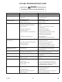
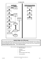
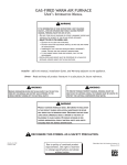
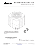
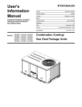
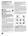
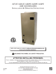
HAVE YOU DISCUSSED WITH YOUR
INSTALLING CONTRACTOR THE OPTIONAL
$400.00 2ND THROUGH 5TH YEAR COMPRESSOR
LABOR ALLOWANCE PROGRAM?
®
C
US
For The United States and Canada only
INSTALLATION & OPERATING
INSTRUCTIONS for
COMBINATION HEATING and
COOLING OUTDOOR UNITS
PGB SERIES
FOR YOUR SAFETY
WHAT TO DO
IF YOU SMELL GAS
• Do not try to light any appliance.
• Do not touch any electrical switches;
DO NOT DESTROY
do not use any phones in your
PLEASE READ CAREFULLY
building.
• Immediately call your gas supplier AND KEEP IN A SAFE PLACE
from a neighbor's phone. Follow the FOR FUTURE REFERENCE.
gas supplier's instructions.
• If you cannot reach your gas supplier,
call the fire department.
FOR YOUR SAFETY
Do not store or use gasoline or
other flammable vapors and
liquids in the vicinity of this or
any other appliance.
All information contained herein is subject to change without notice.
I0-148D
Goodman Manufacturing Company, L.P.
2550 North Loop West, Suite 400, Houston, TX 77092
www.goodmanmfg.com
© 2003-2004 Goodman Manufacturing Company, L.P.
1/04
INDEX
REPLACEMENT PARTS
Introduction ........................................................... 2
ORDERING PARTS
When reporting shortages or damages, or ordering repair
parts, give the complete unit model and serial numbers as
stamped on the unit’s nameplate.
Replacement Parts ............................................... 2
Important Safety Instructions ................................ 2
Replacement parts for this appliance are available through
your contractor or local distributor. For the location of your
nearest distributor, consult the white business pages, the
yellow page section of the local telephone book or contact:
Warnings .............................................................. 2
Physical Dimensions ............................................ 4
Specifications ....................................................... 5
SERVICE PARTS DEPARTMENT
GOODMAN MANUFACTURING COMPANY, L.P.
2550 NORTH LOOP WEST, SUITE 400
HOUSTON, TEXAS 77092
(713) 861 – 2500
Installation Procedure ........................................... 5
Cover Gasket Detail Conversion ........................... 7
Piping .................................................................... 8
Wiring ................................................................... 9
IMPORTANT SAFETY INSTRUCTIONS
Electronic Ignition System................................... 10
RECOGNIZE SAFETY SYMBOLS, WORDS, AND LABELS
The following symbols and labels are used throughout this
manual to indicate immediate or potential hazards. It is the
owner’s responsibility to read and comply with all safety
information and instructions accompanying these symbols.
Failure to heed safety information increases the risk of
property damage, product damage, personal injury or death.
Checkout Procedure ........................................... 10
Lighting Instructions ............................................ 11
wiring Diagrams ................................................. 12
Troubleshooting Chart ......................................... 15
DANGER
Flowchart ............................................................ 16
IMMEDIATE HAZARDS WHICH WILL RESULT IN
PROPERTY DAMAGE, PRODUCT DAMAGE, SEVERE
PERSONAL INJURY AND/OR DEATH.
THIS PRODUCT CONTAINS ELECTRONIC COMPONENTS,
WHICH REQUIRE A DEFINITE GROUND. PROVISIONS ARE
MADE FOR CONNECTION OF THE GROUND. A DEDICATED
GROUND FROM THE MAIN POWER SUPPLY OR AN EARTH
GROUND MUST BE PROVIDED.
WARNING
HAZARDS OR UNSAFE PRACTICES COULD RESULT IN
PROPERTY DAMAGE, PRODUCT DAMAGE, SEVERE
PERSONAL INJURY AND/OR DEATH.
CAUTION
INTRODUCTION
HAZARDS OR UNSAFE PRACTICES WHICH MAY RESULT
IN PROPERTY DAMAGE, PRODUCT DAMAGE, AND/OR
PERSONAL INJURY.
This booklet contains the installation and operating
instructions for your combination gas-electric year-round
furnace-air conditioner. All warnings and precautions within
this booklet must be observed. Improper installation can
result in unsatisfactory operation or dangerous conditions
and void the warranty. Read this booklet and any instructions
packaged with accessories prior to installation. Give this
booklet to the user and explain its provisions. The user should
retain this booklet for future reference.
WARNING
THIS FURNACE IS DESIGN CERTIFIED FOR
INSTALLATION IN BUILDINGS CONSTRUCTED ON SITE
ONLY.
CHECKING PRODUCT RECEIVED
WARNING
Upon receiving the unit, inspect it for damage from shipment.
Claims for damage, either shipping or concealed, should be
filed immediately with the shipping company. Check the unit
model number, specifications, electrical characteristics and
accessories to determine if they are correct. In the event an
incorrect unit is shipped, it must be returned to the supplier
and must NOT be installed. The manufacturer assumes no
responsibility for installation of incorrectly shipped units.
IO-148D
DO NOT USE THIS FURNACE IF ANY PART HAS BEEN
UNDER W ATER. IMMEDIATELY CALL A QUALIFIED
SERVICE TECHNICIAN TO INSPECT THE FURNACE AND
TO REPLACE ANY PART OF THE CONTROL SYSTEM AND
ANY GAS CONTROL THAT HAS BEEN UNDER WATER.
2
1/04
WARNING
WARNING
CARBON MONOXIDE (REFERRED TO AS CO) CAN CAUSE
SERIOUS PERSONAL INJURY OR DEATH.
THE GAS SUPPLY PIPE MUST NEVER BE USED FOR
GROUNDING PURPOSES.
WARNING
WARNING
WHILE CARBON MONOXIDE DETECTORS DO PROVIDE
ADDITIONAL PROTECTION, CURRENT LIMITATIONS TO
THEIR EFFECTIVENESS REQUIRE THAT YOU
OTHERWISE CONTINUE TO FOLLOW APPROPRIATE
INSTRUCTIONS LOCATED IN THE “INSTALLATION &
OPERATING INSTRUCTIONS” AND USERS INFORMATION”
MANUALS RELATING TO PROTECTING PERSONS FROM
THE RISKS OF CARBON MONOXIDE. REVIEW EACH CO
DETECTOR’S MANUFACTURERS’ EXPLANATION OF THEIR
UNIT’S CAPABILITIES AND FOLLOW THE INSTALLATION
AND OPERATING MANUAL WHEN INSTALLING AND
OPERATING SUCH UNITS.
NEVER LAY THIS FURNACE ON ITS FRONT OR REAR.
WARNING
HEATING UNIT SHOULD NOT BE UTILIZED WITHOUT
REASONABLE, ROUTINE, INSPECTION, MAINTENANCE
AND SUPERVISION. IF THE BUILDING IN WHICH ANY
SUCH DEVICE IS LOCATED WILL BE VACANT, CARE
SHOULD BE TAKEN THAT SUCH DEVICE IS ROUTINELY
INSPECTED, MAINTAINED AND MONITORED. IN THE
EVENT THAT THE BUILDING MAY BE EXPOSED TO
FREEZING TEMPERATURES AND WILL BE VACANT, ALL
WATER-BEARING PIPES SHOULD BE DRAINED, THE
BUILDING SHOULD BE PROPERLY W INTERIZED, AND
THE W ATER SOURCE CLOSED. IN THE EVENT THAT THE
BUILDING MAY BE EXPOSED TO FREEZING
TEMPERATURES AND WILL BE VACANT, ANY HYDRONIC
COIL UNITS SHOULD BE DRAINED AS WELL AND, IN SUCH
CASE, ALTERNATIVE HEAT SOURCES SHOULD BE
UTILIZED.
WARNING
DO NOT CONNECT TO OR USE IN CONJUNCTION WITH
THIS UNIT ANY DEVICES FOR THE PURPOSE OF SAVING
ENERGY OR INCREASING OPERATING EFFICIENCIES,
WHICH HAVE NOT BEEN TESTED AND APPROVED BY US
OR DESIGN CERTIFIED FOR USE WITH THIS UNIT.
SERIOUS DAMAGE, REDUCED UNIT PERFORMANCE AND
HAZARDOUS CONDITIONS MAY RESULT FROM THE USE
OF DEVICES WHICH HAVE NOT BEEN APPROVED OR
CERTIFIED.
WARNING
TO ENSURE PROPER INSTALLATION AND OPERATION OF
THIS PRODUCT, COMPLETELY READ AND UNDERSTAND
THESE INSTRUCTIONS PRIOR TO ATTEMPTING TO
ASSEMBLE, INSTALL, MAINTAIN, OR REPAIR. IF THESE
INSTRUCTIONS ARE NOT FOLLOWED PRECISELY THERE
IS A POTENTIAL OF CARBON MONOXIDE POISONING,
WHICH CAN RESULT IN SERIOUS ILLNESS OR DEATH.
CARBON MONOXIDE POISONING HAZARD
Special Warning for Installation of Furnaces or Air Handling Units in
Enclosed Areas such as Garages, Utility Rooms or Parking Areas
WARNING
Carbon monoxide producing devices (such as an automobile, space
heater, gas water heater, etc.) should not be operated in enclosed areas
such as unventilated garages, utility rooms or parking areas because of
the danger of carbon monoxide (CO) poisoning resulting from the exhaust
emissions. If a furnace or air handler is installed in an enclosed area such
as a garage, utility room or parking area and a carbon monoxide producing
device is operated therein, there must be adequate, direct outside
ventilation.
THIS FURNACE WAS EQUIPPED AT THE FACTORY FOR
USE WITH NATURAL GAS ONLY. LIQUID PETROLEUM (L.P.)
CONVERSION, IF REQUIRED, MUST BE PERFORMED BY
A QUALIFIED TECHNICIAN FAMILIAR WITH PERFORMING
THIS TYPE OF CONVERSION. IF L.P. CONVERSION IS
REQUIRED, ALL INSTRUCTIONS INCLUDED WITH THE
FACTORY AUTHORIZED KIT MUST BE FOLLOWED. THE
ONLY KIT THAT MUST BE USED FOR THIS CONVERSION
IS THE FACTORY AUTHORIZED LPT-01. FAILURE TO
FOLLOW THOSE INSTRUCTIONS EXPLICITLY MAY CAUSE
FIRE, EXPLOSION, PROPERTY DAMAGE, PERSONAL
INJURY OR DEATH.
IO-148D
This ventilation is necessary to avoid the danger of CO poisoning which
can occur if a carbon monoxide producing device continues to operate in
the enclosed area. Carbon monoxide emissions can be (re)circulated
throughout the structure if the furnace or air handler is operating in any
mode.
CO can cause serious illness including permanent brain damage or death.
B10259-216
3
1/04
PHYSICAL DIMENSIONS - FIGURE 1
BLOWER & CONDENSER ACCESS PANEL
FLUE EXHAUST
2 1/8"
O
DISCHARGE PRESSURE SERVICE PORT
SUCTION PRESSURE SERVICE PORT
POWER WIRE ENTRANCE
CONTROL WIRE ENTRANCE
N
K
M
L
CONDENSATE DRAIN
CONNECTION (3/4" NPT) FEMALE
SUPPLY GAS ENTRANCE
FRESH AIR
DAMPER OPENING
C
B
E
"
/16
25
D
RETURN
/4"
21
5"
SUPPLY
F
A
I
/4"
21
H
G
/2"
11
/4"
21
DIMENSIONS
(INCHES)
A
B
C
D
E
F
G
H
I
K
L
M
N
O
ACCESSORY MODEL NUMBERS
ALL PGB MODELS
MODEL NUMBERS
LP Conversion Kit
Honeywell HSP
LPM-01
Room Thermostat
CHT 18-60
High and Low Pressure Kit
HLPK-01
Low Ambient Kit
LA-01
IO-148D
4
PGB024050
PGB024075
PGB030050
PGB030075
PGB036050
PGB036075
PGB030100
PGB036100
PGB042075
PGB042100
PGB042125
PGB042150
PGB048075
PBG048100
PGB048125
PGB048150
PGB060100
PGB060125
PGB060150
31 1/8
52
38 3/4
13 3/8
18 3/8
15
15 1/4
13 3/4
18 3/4
30
16 3/8
7
7 5/8
12 3/8
31 1/8
52
43 3/4
16 3/4
20 3/8
15
15 1/4
16 3/4
20 3/4
30
18 3/8
7
7 5/8
12 3/8
33 5/8
55 3/8
58 1/8
24 5/8
26 5/8
17
17 1/4
25
27
32 1/2
27 3/4
7 1/4
10 1/8
14 7/8
1/04
The air deflector plates and shields are in a box located in
the return air compartment for shipping. Secure one to the
upper gas panel as shown in Figure 2 and secure the other
two as shown in Figure 3. Air deflector plates are used on all
PGB units equipped with a shield.
SPECIFICATIONS
GENERAL
These Combination Gas Heating/Electric Cooling Rooftops
are available in 46, 69, 92, 115, and 140,000 Btu/Hr. heating
inputs and cooling capacities of 2, 2½, 3, 3½, 4, and 5
nominal tons of cooling. Units are convertible from horizontal
supply and return to bottom supply and return by relocation
of cap panels.
D
The units are weatherized for installing outside of the building.
Units are not to be installed inside the structure.
A
B
AIR
DEFLECTOR
PLATE
The information on the rating plate is in compliance with the
FTC and DOE rating for single phase units in the U.S.A.
The following information is for three phase units which are
not covered under the DOE certification program in the U.S.A.
2"
1. The energy consumption of the ignition system used
with the unit is 9 watts.
2. The efficiency rating of this unit is a product thermal
efficiency rating determined under continuous operating
conditions independent of any installed system.
C
GAS PANEL
4"
IMPORTANT: The United States Environmental
Protection Agency (EPA) has issued various regulations
regarding the introduction and disposal of refrigerants in
this unit. Failure to follow these regulations may harm
the environment and can lead to the imposition of
substantial fines. Because these regulations may vary
due to the passage of new laws, we suggest that any
work on this unit be done by a certified technician.
Should you have any questions, please contact the local
office of the EPA.
SHIELD DETAIL
CHASSIS
SMALL
MEDIUM
LARGE
A
10"
10"
20"
B
2 3/16"
2 3/16"
5 7/16"
C
16"
16"
13 1/2"
D
2 1/4"
3 3/4"
4"
(Shield Required on Small, Medium and Large Chassis)
FIGURE 2
MAJOR COMPONENTS
The unit includes a hermetically-sealed refrigerating system
(consisting of a compressor, condenser coil, evaporator coil
with flowrator assembly), an indoor blower, a condenser fan,
a heat exchanger assembly, gas furnace burner and control
assembly, combustion air motor and blower, and all
necessary internal electrical wiring. The cooling system of
these units is factory-evacuated, charged and performance
tested. Refrigerant amount and type are indicated on rating
plate.
C
A
D
E
B
INSTALLATION PROCEDURE
GENERAL
In the U.S.A., installation must conform with local building
codes or, in the absence of local codes, with the National
Fuel Gas Code, ANSI Z223.1.
INNER SHIELD
OUTER SHIELD
Before attempting any installation, the following points should
be considered:
• Structural strength of supporting members
• (Rooftop installation)
• Clearances and provision for servicing
• Power supply and wiring
• Gas supply and piping
• Air duct connections
• Drain facilities and connections
• Location for minimum noise
IO-148D
CHASSIS
SMALL
MEDIUM
LARGE
A
1"
1"
1"
B
10"
10"
10"
C
2 1/2"
2 1/2"
2 1/2"
D
8 1/4"
8 1/4"
8 1/4"
E
2"
2"
2 3/8"
FIGURE 3
5
1/04
This unit is designed for outdoor installations. It can be
mounted on a slab or rooftop. It is not to be installed within
any part of a structure such as an attic, crawl space, closet,
or any other place where condenser air flow is restricted or
other than outdoor ambient conditions prevail. Since the
unit is to be installed outdoors, it is important to consult
your local code authorities at the time of first installation.
Many local codes prohibit the use of a combination gaselectric unit having the heat exchanger downstream of the
evaporator. The design of this unit meets this code
requirement in that the return air passes over the heat
exchanger first before coming into contact with the evaporator
coil preventing condensation from taking place within the heat
exchanger.
2. Refer to Figure 5 for roof curb details.
UNIT
REMOVE BOTH RAILS
BEFORE INSTALLING
DUCT RETURN
GASKET (FULL
PERIMETER AND
ON DIVIDERS)
(SUPPLIED WITH
CURB)
SLAB INSTALLATION - FIGURE 4
1. Select a location where external water drainage cannot
collect around unit.
SUPPLY DUCT
DUCT FLANGE
ROOF CURB
2. Provide a level concrete slab (min. flush with all four sides
of the unit). The slab should be isolated from the
foundation wall. Ensure that there is no obstruction to
condenser or combustion air by fences, shrubs, etc.
NAILER
GASKET
UNIT
ROOF CURB
NAILER STRIP
3. The location of the unit should be such as to provide
proper access for inspection and servicing.
INSULATION*
DUCT*
COUNTER FLASHING*
4. Bottom rails are supplied for slab installation.
14"
CANT STRIP*
ROOF FELT*
INSULATION*
ROOF DECK*
ROOF STRUCTURAL
MEMBER*
12"
*BY CONTRACTOR
ROOF CURB DETAIL
FIGURE 5
3"
12"
3. Refer to Figure 6 for rigging details.
12"
48" SERVICE
CLEARANCES TO COMBUSTIBLE MATERIALS
AND OUTSIDE SLAB INTALLATION
FIGURE 4
ROOFTOP INSTALLATION
1. Before locating the unit on the roof, make sure that the
strength of the roof and beams is adequate at the point
to support the weight involved. This is very important
and installer’s responsibility. The following list shows
approximate weight of unit.
SIZE
2 TON
2 1/2 TON
3 TON
3 1/2 TON
4 TON
5 TON
WEIGHT (lb.)
370
385
395
465
500
545
RIGGING DETAIL
FIGURE 6
IO-148D
6
1/04
4. The unit should be placed on a solid level platform of
adequate strength. The mounting structure must be
constructed as to support the unit a minimum of 3"
above the roof deck. An angle iron stand of proper
strength may be used to provide level support for the
unit. See Figure 7 for unit bottom rail constructions.
This unit should be placed as close to the space to be air
conditioned as possible. Adequate clearance must be
maintained as indicated in the Section called “Clearances”.
Ducts should be run as directly as possible to supply and
return outlets. Use of non-flammable weatherproof flexible
connectors on both supply and return connections at unit to
reduce noise transmission is recommended.
It is preferable to install the unit on the roof of the structure if
the registers or diffusers are located on the wall or in the
ceiling. A slab installation could be considered when the
registers are low on a wall or in the floor.
On duct work exposed to outside air conditions of temperature
and humidity, use a minimum of 2" of insulation with a good
R factor, and vapor barrier. Distribution system in attic furred
space, or crawl space should be insulated with at least 2" of
insulation. Usually, 1/2" to 2" thickness of insulation is
sufficient for duct work inside the air conditioned space.
BASE PAN
2 13/16"
1 3/4"
3"
B
D*
C
Balancing dampers should be provided for each branch duct
in the supply system. Duct work should be properly
supported from the structure.
A
FIGURE 7
FILTERS
Filters are not provided with unit, and must be supplied and
installed in the return air system by the installer. A field
installed filter grille is recommended for easy and convenient
access to the filters, for periodic inspection and cleaning.
Filters must have adequate face area for the rated air quantity
of the unit. See table below for recommended filter size.
BASE RAIL DETAIL
UNIT
2 - 3 TON (Small)
A
51 7/8"
B
9"
C
31 3/4"
D*
21 1/16"
3 - 3 ½ TON( Medium)
51 7/8"
9"
31 3/4"
21 1/16"
3 ½ - 5 TON (Large)
55 1/4"
9"
35 1/4"
23"
*RELOCATION DIM. FOR BASE CHANNEL IN DOWN DISCHARGE OPTION.
UNIT
5. The location of the unit on the roof should be such as to
provide proper access for inspection and servicing.
Min. Filter
(1)
Size
20x20x1
FOR OUTDOOR INSTALLATION ONLY
The venting as supplied with the unit must be used without
alteration or addition. Consult your local utility BEFORE
installing.
2 1/2 TON
3 TON
(1)
(1)
20x25x1 25x25x1
3 1/2 /
4 TON
5 TON
(2)
(2)
20x20x1 20x25x1
CLEARANCES
The following minimum clearances must be observed for proper
unit performance and serviceability.
1. Provide 60" minimum clearance between top of unit and
maximum 3 foot overhang.
DUCTING
Duct work should be fabricated by the installing contractor
in accordance with local codes. Industry manuals, such
as NESCA (National Environmental Systems Contractors
Association, 1501 Wilson Blvd., Arlington, Virginia 22209),
may be used as a guide when sizing and designing the
duct system
2. Unit is design certified for application on combustible
flooring with base rails in place as shown on Figure 4.
3. See Figure 4 for illustration of minimum installation
combustible material clearances.
4. The unit may be installed directly on wood flooring or on
(Class A, Class B, or Class C, in U.S.A.) roof covering
materials if the bottom rails are in place.
WARNING
DO NOT, UNDER ANY CIRCUMSTANCES, CONNECT
DUCT WORK TO ANY OTHER HEAT PRODUCING DEVICE
SUCH AS FIREPLACE INSERT, STOVE, ETC.
UNAUTHORIZED USE OF SUCH DEVICES MAY RESULT
IN FIRE, CARBON MONOXIDE POISONING, EXPLOSION,
PROPERTY DAMAGE PERSONAL INJURY OR DEATH.
IO-148D
2 TON
COVER GASKET DETAIL CONVERSION
1. Remove screws and covers from bottom of supply and
return sections.
2. Using covers as a template drill 1/8” diameter holes in
unit from around the duct openings.
7
1/04
SUPPLY AIR
COVER
5.
RETURN AIR COVER
A 1/8" N.P.T. plugged tapping, accessible for test gauge
connection, must be installed immediately upstream of
the gas supply connection to the furnace.
Capacity of gas pipe of different diameters and length in
3
ft /hr. with a pressure drop of 0.3" W.C. and a specific
gravity of 0.60 (natural gas).
Pipe
Size*
Length
of
Pipe
in Feet
INSULATION
¾
1
1¼
1½
132
92
73
63
56
50
46
43
278
190
152
130
115
105
96
90
520
350
285
245
215
195
180
170
1050
730
590
500
440
400
370
350
1600
1100
890
760
670
610
560
530
*Nominal size of iron pipe in inches.
SUPPLY/RETURN
AIR COVER
After the length of pipe has been determined, select the
pipe size which will provide the cubic feet per hour required
for the gas input rating of the furnace. By formula:
FOAM TAPE
AROUND FLANGE
FIGURE 8
Cubic feet of
gas required
IMPORTANT NOTE: When casing panels, other than access
panels, are removed for service, any insulation that is
damaged or torn must be replaced by identical material.
=
Gas input of appliance (BTU/hr)
Heating value of gas (BTU/ft.3)
The gas input of the appliance is marked on the specification
plate. The heating value of the gas may be determined by
contacting the gas utility or gas supplier.
PIPING
GAS CONNECTION
1. The gas line connection to the unit must be made through
the gas pipe opening provided into the 1/2" inlet valve
opening. See Figure 9 for typical piping.
GROUND UNION
JOINT-INSTALLED
EXTERIOR TO CASING
MANUAL SHUT-OFF
WITHIN 4' (VERTICAL)
OF ROOF/SLAB
2. The gas line to the furnace should be of adequate size
to prevent undue pressure drop and should never be less
than 1/2". A trap should be installed in the gas supply
line as close to the unit as possible. An outside ground
joint union should be installed to connect the gas supply
to the control assembly gas valve.
1/8" NPT PLUG
FOR MEASURING
SUPPLY GAS
PRESSURE
DRIP LEG 4"-8"
LONG
NOTE: DRIP LEG
MUST BE CAPPED
3. Gas controls have been factory installed. Another
manual shut off valve should be installed where local
codes specify a shut-off valve is to be located outside
the unit casing. (See Figure 9.)
UNIT GAS SUPPLY CONNECTION
MUST BE TIGHT
ROOF OR GROUND LEVEL INSTALLATION
Suggested Gas Piping
4. Piping should be tight. A pipe compound resistant to
the action of liquefied petroleum gases must be
used at all threaded pipe connections.
FIGURE 9
CHECKING INPUT TO UNIT
1. Gas input must never exceed the figure shown on the
rating plate.
CAUTION
THE FURNACE AND ITS INDIVIDUAL SHUT-OFF VALVE
MUST BE DISCONNECTED FROM THE GAS SUPPLY
PIPING DURING ANY PRESSURE TESTING OF THAT
SYSTEM AT TEST PRESSURES IN EXCESS OF 1/2 POUND
PER SQUARE INCH GAUGE OR THE SYSTEM MUST BE
ISOLATED FROM THE GAS SUPPLY PIPING SYSTEM BY
CLOSING ITS INDIVIDUAL MANUAL SHUT-OFF VALVE
DURING ANY PRESSURE TESTING OF THIS GAS SUPPLY
SYSTEM AT PRESSURES EQUAL TO OR LESS THAN 1/2
PSIG.
2. Manifold pressure can be measured with a manometer
attached to the 1/8" pipe tap provided in the gas valve.
Manifold pressure for Natural Gas should be 3 1/2" W.C.
and for L.P./Prop. gas 10" W.C. To measure the input
using a gas meter, proceed as follows:
a. Turn off gas supply to all appliances except furnace.
With furnace burning, time the two cubic foot hand
on the gas meter dial plate for one revolution in
seconds and divide this reading by two. This will
give seconds per cubic foot of gas being delivered
to the furnace.
To check for leaks in piping, use a soap and water solution
or other approved method. DO NOT USE AN OPEN FLAME.
IO-148D
10
20
30
40
50
60
70
80
½
8
1/04
b. Assuming natural gas with heating value of Btu/Cu.
Ft. and Sec./Cu. Ft. being determined from step 2a,
then
1000x3600
= Input Btu/Hr
Sec./Cu. Ft.
WIRING
All wiring should be made in accordance with the National
Electrical Code in the U.S.A. Determine the availability of
sufficient power to operate the unit. The voltage at power
supply should be checked to make sure it corresponds to
the unit’s RATED VOLTAGE REQUIREMENT. Install a
branch circuit disconnect near the unit, in accordance with
the N.E.C. or local codes. Wire sizes should be determined
from the unit nameplate ampacity and in accordance with
Table 2, the National Electrical Code. Under no
circumstances should wiring be sized smaller than is
recommended by either of these two sources. See wiring
diagram for maximum fuse or HACR breaker size.
3. To adjust the regulator, remove the cap on top of the gas
valve. To decrease the pressure (decrease input to
furnace), turn the screw below the cap counterclockwise.
To increase the pressure (increase input to furnace), turn
the screw clockwise. The manifold pressure should not
vary more than plus or minus 0.3" W.C. (minimum 3.2"
W.C.; maximum 3.8" W.C. for natural gas).
Note: For elevations up to 2,000 feet, full input ratings
apply. In U.S.A., for elevations over 2,000 feet, reduce
input 4% for each 1,000 feet above sea level by changing
the burner orifices. ( See appropriate marking on the
unit for input.)
BRANCH CIRCUIT AMPACITY
TABLE 2
4. The furnace is to be adjusted to obtain a temperature
rise within the range specified on the appliance rating
plate.
BURNERS
Burners for these units have been designed so that field
adjustment is not required. Burners are accessible for easy
cleaning when required.
SUPPLY WIRE
LENGTH - FEET
15
20
25
30
35
40
45
50
200
150
100
75
50
6
8
10
12
14
4
6
8
10
12
4
6
8
8
18
4
4
6
8
10
3
4
6
6
8
3
4
6
6
8
2
3
4
4
6
2
3
4
4
6
All exterior wiring must be within approved weatherproof
conduit. The unit must be permanently grounded in
accordance with local codes, or in the absence of local codes,
with the N.E.C. ANSI/NFPA NO. 70-1987 or latest edition in
the U.S.A.
CONDENSATE DRAIN
The condensate drain connection of the evaporator is a half
coupling of 3/4" N.P.T. A trap must be provided to have proper
condensate drainage.
NOTE: Some single phase units are equipped with a single
pole contactor. Caution must be exercised when servicing
as only one leg of the power supply is broken with the
contactor.
Install condensate drain trap as shown in Figure 10. Use 3/
4" drain connection size or larger. Do not operate without
trap. Unit must be level or slightly inclined toward drain. An
auxiliary drain is also provided.
To wire units, make the following high and low voltage
connections.
DRAIN CONNECTION
HIGH VOLTAGE WIRING
Single phase
Two leads should be connected to terminals L1 and L2 in
the electrical control section, using wire sizes specified
in wiring table.
2" MINIMUM
UNIT
FLEXIBLE
TUBING - HOSE
OR PIPE
3" MINIMUM
Three phase
Three leads should be connected to terminals L1, L2, and
L3 in the electrical control section, using wire sizes
specified in wiring table.
A POSITIVE LIQUID
SEAL IS REQUIRED
FIGURE 10
LOW VOLTAGE WIRING
COMBUSTION AIR FAN
Inspect fan motor blower housing prior to each heating season
to see that both are clear of obstructions and turn freely.
NOTE: Some motors are dual voltage and require wiring
change for 208V operation. See wiring diagram.
Connect 24 V. wires from the thermostat to the corresponding
wires in control box using No. 18 AWG as follows:
FURNACE ACCESS PANEL
Design of this system requires that the combustion
compartment be sealed for proper furnace operation. Never
operate furnace with access panel removed or screws loose.
The glass inspection port allows observation of the burner
operation with panel in place.
IO-148D
9
LEAD
THERMOSTAT
NOTES
White
W (Heat)
-
Green
G (Fan)
-
Yellow
Y (Cool)
-
Red
R(24V)
-
Orange
Pink
Y1
Y2
Only when economizer is utilized
Only when economizer is utilized
1/04
The flue passageways and vent system should be inspected
and cleaned (if required) by a qualified serviceman after the
second year of service and annually thereafter using this
procedure. Combustion air motor and blower should be
checked for obstructions prior to each heating season.
INTERNAL WIRING
A diagram of the internal wiring of this unit is located on the
interior of the electrical box cover. If any of the original wire,
which was supplied with the appliance, must be replaced,
the wire gauge and insulation must be the same as original
wiring.
1. Turn off all power to the furnace and set the thermostat
lever to the lowest temperature.
2. Shut off the gas supply to the furnace either at the meter
or at a manual valve in the supply piping.
3. Remove the control door from the furnace.
4. Turn the gas control knob to the “off” position.
5. Mark the individual wires to the gas control for identifying
purposes when they are to be re-connected.
6. Remove wires from the gas valve.
7. Using wrenches, separate the ground-joint union in the
supply piping at the furnace.
8. Remove piping between the control valve and the groundjoint union.
9. Remove the burner assembly from the furnace by
removing the (4) screws securing the burner box and lift
the burner cover off.
10. Each heating section has a flue collector box cover in
the flue outlet. Remove the screws in the collector box
and wires from the combustion motor.
11. The furnace sections can now be cleaned by the use of
a wire brush with a flexible handle. Slide brush through
each section. Sweeping back and forth through each
section will loosen any scale allowing it to fall to the
bottom of the sections. The debris can now be brushed
out of the bottom sections or cleaned with the nozzle of
a vacuum cleaner.
12. Check the ports on the gas burners to make certain that
they are clean. Brushing or jarring may loosen any
accumulation. Standing the burner assembly on end
will allow any scale to fall out of the entrance end of the
burners.
13. Reinstall the flue collector box & combustion motor.
14. Replace the burner assembly and secure in position.
15. Reinstall the gas supply piping between the gas control
and the ground joint union.
16. Re-connect all wiring that was previously disconnected.
17. Turn on the gas supply and check for leaks.
18. Turn on the electric power.
19. Follow the lighting procedure. Due to the cleaning
operation, the system will contain air. Therefore, the
system may have to be cycled a couple of times before
the pilot gas will ignite.
Transformer and combustion air motor are factory wired for
230 volts on 208/230 volt models. See wiring diagram for
208 volt wiring.
1. For branch circuit wiring (main power supply to unit
disconnect), the minimum wire size for the length of run
can be determined from Table 2 using the circuit ampacity
found on the unit rating plate. From the disconnect to
the unit, the smallest wire size allowable in Table 2 may
be used, as the disconnect must be within the sight of
the unit.
2. Wire size based on 60oC rated wire insulation and 30oC
Ambient Temp. (86oF).
3. For more than three( 3) conductors in a raceway or cable,
see the N.E.C. for derating the ampacity of each
conductor.
ELECTRONIC IGNITION SYSTEM
MODE OF OPERATION
See the Sequence of Operation Flowchart for Mode of
Operation.
OPERATING INSTRUCTIONS
Instructions to start and shut off the furnace are in the “lighting
instructions” on the unit and in the user’s manual.
The initial start up on a new installation may require the
control system to be energized for some time until any air
has bled through the pilot burner and fuel gas is available at
the pilot.
CHECK OUT PROCEDURE
Before leaving the installation, three (3) complete operating
cycles should be observed. Carefully follow the lighting
instructions. Run the unit through a normal operating cycle
and observe the operation.
SERVICE
Service should only be conducted by qualified service
personnel. See TroubleShooting Flowchart.
MAINTENANCE
The heat exchanger should operate for many years without
excessive scale buildup in the flue passageways. However,
it is recommended that the user have a qualified service man
to inspect the flue passageways, the vent system, and
burners for continued safe operation, paying particular
attention to deterioration from corrosion or other sources.
IO-148D
10
1/04
LIGHTING INSTRUCTIONS
FOR YOUR SAFETY READ BEFORE OPERATING
WARNING
A. This appliance does not have a pilot. It
is equipped with an ignition device which
automatically lights the burners. Do not
try to light the burners by hand.
B. BEFORE OPERATING smell around
the appliance area for gas. Be sure to
smell next to the floor because some gas
is heavier than air and will settle on the
floor.
WHAT TO DO IF YOU SMELL GAS
Do not try to light any appliance.
Do not touch any electric switch;
do not use any telephone in your
building.
Immediately call your supplier
from a neighbor's phone. Follow
the gas suppliers instructions.
If you do not follow these instructions exactly,
a fire or explosion may result causing property
damage, personal injury or loss of life.
If you cannot reach your gas supplier,
call the fire department.
C. Use only your hand to move the gas
control switch or knob. Never use
tools. If the gas control switch or knob
will not operate, don't try to repair it,
call a qualified service technician.
Force or attempted repair may result in
a fire or explosion.
D. Do not use this appliance if any part
has been under water. Immediately call
a qualified service technician to inspect
the appliance and to replace any part of
the control system and any gas control
which has been under water.
OPERATING INSTRUCTIONS
1. STOP! Read the safety information
above on this label.
2. Set the thermostat to lowest setting.
3. Turn off all electric power to the
appliance.
4. This appliance is equipped with an
automatic ignition system which
automatically lights the burners. Do not
try to light the burners by hand.
5. Remove control access panel.
6. Move the gas control switch or knob
to "OFF".
GAS CONTROL
SWITCH SHOWN
IN "ON" POSITION
7. Wait five (5) minutes to clear out any
gas. If you then smell gas, STOP!
Follow "B" in the safety information
above on this label. If you don't smell
gas, go to the next step.
8. Move the gas control switch or knob
to "ON".
9. Replace control access panel.
10. Turn on all electric power to the
appliance.
11. Set the thermostat to the desired
setting.
12. If the appliance will not operate,
follow the instructions "To Turn Off Gas
To Appliance" and call your service
technician or gas supplier.
KNOB
ON
OFF
GAS CONTROL
GAS CONTROL
SWITCH SHOWN
IN "ON" POSITION
TO TURN OFF GAS TO APPLIANCE
1. Set the thermostat to its lowest setting.
2. Turn off all electric power to the
appliance if service is to be performed.
4. Move the gas control switch or knob
to "OFF". Do not force.
5. Replace control access panel.
3. Remove control access panel.
WARNING: Improper
installation, adjustment,
alteration, service or
maintenance can
cause injury or
property damage.
Refer to the user's
information manual
provided with this
furnace. For assistance
or additional information
consult a qualified
installer, service agency
or the gas supplier.
This furnace must be
installed in accordance
with the manufacturers
instructions and local
codes. In the absence
of local codes, follow
the National Fuel Gas
Code, ANSI Z223.1.
For indoor installation.
PGB & PGJ
For outdoor
installation only.
WARNING: If not
installed, operated
and maintained in
accordance with the
manufacturer's
instructions, this
product could expose
you to substances
in fuel combustion
which can cause
death or serious
illness and which
are known to the
State of California to
cause cancer, birth
defects or other
reproductive harm.
This product contains
fiberglass insulation.
Fiberglass insulation
contains a chemical
known by the State of
California to cause
cancer.
FOR YOUR SAFETY
Do not store or use gasoline or
other flammable vapors and liquids in the vicinity of this
or any other appliance.
IO-148D
11
B14933-239
1/04
WIRING DIAGRAM - SINGLE PHASE
ALS
HEAT COOL
UNUSED
L1
L1
W
NOTE #3
6
11
8
5
2
7
4
1
BL
BL
O
O
THC-FIELD WIRING
O
THC-NO ECONOMIZER
BL
W
R
W
R
R
R
LS
G
W
W
G
G
R
R
Y
Y
THC-WITH ECONOMIZER OPTION
1-STAGE COOLING
G
W
O
W
W
G
G
R
R
Y 1
W
R
B
R
B
F
W
C
R
Y1
Y 1
Y 2
Y 2
L2
H
BL
Y
BJB
W
L1
G
R
T2
R
Y
R
G
BL
CC
T1
R
W
W
R
NOTE #5
B
Y
2-STAGE COOLING
Y
CAP1
GV
VM
W
ECON
B
C
ES
O
Y
R
P
2
IGN
FS
O
BR
R
R
SA
M
3
BR
3
10
MV
BL
1
W
GV
B
R
R
9
GAS VALVE
MV
W
R
12
(ALT.) W. R.
HONEYWELL
GAS VALVE
RS
3
C
W
FS
BR
2
208
TRANS
24V
BR
D1
IIC
W
B
W
1
240
W
L2 L2 L2 L2
B
R
NOTE #2
B
B
GRD
B
Y
Y
PU
B
G
W
R
R
PLUG FURNISHED
W ITH ECONOMIZER
G
BL
B
C
B
BR
S
Y
R
PU
R
CM
COMP
B
B
EM
BR
BR
Y
POWER SUPPLY
5
5
2
O
1
4
4
1
R
W
G
Y 2 Y1
L2
SUPPLY VOLTAGE
208-230/1/60
COMPONENT LEGEND
CH
C
L1
COMP
C
S
H
CAP1
L1
H
L1
D1
L2
CC
CAP 2
F
CM
(LOW)
EM
L2
L1
L2
IGN
FS
4
WIRING
CONDENSER MOTOR
LOW VOLTAGE
FIELD INSTALLED POWER
FIELD INSTALLED CONTROL
CONTRACTOR
CRANKCASE HEATER
END SWITCH
EVAPORATOR MOTOR
FLAME SENSOR
GAS VALVE
INTEGRATED IGNITION CONTROL
IGNITOR
LIMIT SWITCH
WIRE CODE
B
BLACK
BL
BR
G
O
PK
PU
R
W
Y
BLUE
BROWN
GREEN
ORANGE
PINK
PURPLE
RED
WHITE
YELLOW
NOTES
LS
5
LINE VOLTAGE
PL PLUG
RS ROLLOUT SWITCH
SA START ASSIST
THC THERMOSTAT HEAT & COOL
TRANS TRANSFORMER
VM VENT MOTOR
2
1
FS
UNMARKED TERMINAL
CAP CAPACITOR
COMP COMPRESSOR
CC
CH
ES
EM
FS
GV
IIC
IGN
LS
L2
VM
FUSE
MARKED TERMINAL
BJB BLOWER JUNCTION BOX
CM
(HIGH)
C
L1
WIRE SPLICE
ALS AUXILLARY LIMIT SWITCH
T2
R
T1
ECONOMIZER
TO THERMOSTAT
208-230/1/60
CAP 2
CC
3
PL1
2
(OPTIONAL)
NOTE #4
L1
PLE
3
PK
1. REPLACEMENT WIRE MUST BE THE SAME SIZE AND TYPE OF
ALS
INSULATION AS ORIGINAL.(USE COPPER CONDUCTOR ONLY).
RS
3
MV
IIC
6
GV
2. FOR 208 VOLT TRANSFORMER OPERATION MOVE WHITE WIRE
MV
FROM TERMINAL 1 TO TERMINAL 2 ON TRANSFORMER.
3. FOR 208 COMBUSTION MOTOR OPERATION CONNECT BLACK LEAD
ES
IN PLACE OF RED LEAD AT IIC (D1).
8
7
9
4. CRANKCASE HEATER (OPTIONAL).
ECON
10
12
5. START ASISST USED ON MODELS WITH INERTIA "A" SHELL
COMPRESSORS ONLY.
CC
11
6
5
4
3
2
1
PL1
G
R
W
Y1
Y2
Y
TO THC
MAX FUSE SIZE
MAX HACR BREAKER SIZE
2 TON
2.5 TON
3 TON
3.5 TON
4 TON
5 TON
2 TON
2.5 TON
3 TON
3.5 TON
4 TON
5 TON
25
35
40
50
50
60
STATUS LIGHT
20
30
40
50
50
60
208-230/1/60
EQUIP. STATUS
ON
NORMAL OPERATION
OFF
NO POWER OR
INTERNAL CONTROL
FAULT
IGNITION FAILURE
OR
OPEN ROLLOUT
SWITCH
OR
OPEN AUX. LIMIT
1 BLINK
I N S T A L L E R /S E R V I C E M A N
THE STATUS LIGHT ON THE FURNACE CONTROL MAY
B E U S E D A S A G U ID E T O T R O U B L E S H O O T I N G T H I S
APPLIANCE. STATUS LIGHT CODES ARE AS FOLLOWS:
SWITCH
2 BLINKS
3 BLINKS
LABEL MAT'L: WHITE VINYL
LABEL SIZE: 6 X 11
B29120-02D IS ADHESIVE BACKED LABEL
B29121-02D IS 8.5 X 11.0 PAPER LABEL
END SWITCH
OPEN
END SWITCH CLOSED
W ITHOUT INDUCER ON
4 BLINKS
OPEN LIMIT SWITCH
5 BLINKS
FALSE FLAME SENSED
6 BLINKS
COMPRESSOR
OUTPUT DELAY
CHECK
CHECK INPUT POWER
CHECK FUSE ON CONTROL
REPLACE CONTROL
GAS FLOW
GAS PRESSURE
GAS VALVE
FLAME SENSOR
FLAME ROLLOUT
BAD SWITCH
AUX. LIMIT OPEN
VENTER
END SWITCH
VENTER
END SWITCH
MAIN LIMIT OPEN
BAD SWITCH
STICKING GAS VALVE
3 MIN. COMP.
ANTI-CYCLE TIMER
B29121-02D
IO-148D
12
1/04
WIRING DIAGRAM - THREE PHASE
W
BL
R
R
1
2
3
2
4
C
NOTE #2
1
240
BL
2
208
TRANS
24V
X
COOL
1
HONEYWELL HSP
GAS VALVE/IGNITION CONTROL
BL
K1
K2
3 1
4 2
BL
W
W
K3
PILOT/
SENSOR
ASSEMBLY
BR
O
S
B
3
C
R
R
HEAT
W
B
W
W
SEC
N
DI
1
XFMR
LEADS
MOTOR
BR
UNUSED
B
R
BR
O
ALS
W
Z1
Z2
W
T
W
I
N
R
THC-FIELDWIRING
W
O
THC-NO ECONOMIZER
W
Y
BR
C
SPEED
OFF
Y
C
G
Y
W
R
O
CLT
B
DELAY
1
2
3
O
4
LS
UP
W
W
G
G
R
R
Y
Y
RS
NOTE #5
B
Y
B
Y
B
R
CC
T2
L1
CAP1
L2
ES
L3
B
W
W
G
R
R
Y1
Y1
Y2
Y2
Y
POWER
SUPPLY
R
C
B
G
208-230/
3/60
PLUG FURNISHED
WITH ECONOMIZER
Y
S R
CM
COMP
B
B
PK
BR
Y
BL
BR
BR
R
Y1
B
TO THC
EM
G
R
NOTE #3
Y
PU
Y R Y2
G W Y1
W
G
B
BR
B
W
2-STAGE COOLING
VM
R
B
R
BL
PU B Y/R
O
T3
R
W B Y
BJB
O
Y
BL
W
W
Y
T1
B
Y
R
R
BL
G
THC-WITH ECONOMIZER OPTION
1-STAGE COOLING
3
3
PL1
PK
2
5
5
2
O
1
4
4
1
ECONOMIZER
(OPTIONAL)
NOTE #4
O
PLE
G
G
CAP 2
L1
L3
L2
SUPPLY VOLTAGE
208-230/3/60
COMPONENT LEGEND
WIRE SPLICE
CH
CC
T1
N2
T2
R
C
COMP
CAP 2
CC
S
CM
(HIGH)
(LOW)
EM
N3
VM
C
S1
H
S1
D1
S1
T3
TFC
TFC
4
MV
1
6
PILOT/
SENSOR
ASSEMBLY
WIRE CODE
B
BLACK
BL
BR
G
O
PK
PU
R
W
Y
BLUE
BROWN
GREEN
ORANGE
PINK
PURPLE
RED
WHITE
YELLOW
1. REPLACEMENT WIRE MUST BE THE SAME SIZE AND TYPE OF
INSULATION AS ORIGINAL.(USE COPPER CONDUCTOR ONLY).
ALS
IN PLACE OF RED LEAD AT TFC (D1).
RS
ES
3
G
FROM TERMINAL 1 TO TERMINAL 2 ON TRANSFORMER.
3. FOR 208 COMBUSTION MOTOR OPERATION CONNECT BLACK LEAD
LS
LIMIT
4. CRANKCASE HEATER (OPTIONAL).
5. COMP. LOCKOUT TIMER USED ONLY ON MODELS EQUIPPED WITH
SCROLL COMPERSSORS.
W
3
4
CLT
CC
1
2
CLT
6
5
4
3
2
1
PL1
R
LOW VOLTAGE
FIELD INSTALLED POWER
FIELD INSTALLED CONTROL
2. FOR 208 VOLT TRANSFORMER OPERATION MOVE WHITE WIRE
LIMIT
R
WIRING
NOTES
2
1 3
2 4
5
LINE VOLTAGE
GV GAS VALVE
IC IGNITION CONTROL
LS LIMIT SWITCH
PL PLUG
RS ROLLOUT SWITCH
SA START ASSIST
TFC TIMED FAN CONTROL
THC THERMOSTAT HEAT & COOL
VM VENT MOTOR
C
HONEYWELL HSP
GAS VALVE/IGNITION CONTROL
GV&IC
CAP CAPACITOR
COMP COMPRESSOR
ES END SWITCH
EM EVAPORATOR MOTOR
S2
HONEYWELL
BJB BLOWER JUNCTION BOX
UNMARKED TERMINAL
CC CONTRACTOR
CH CRANKCASE HEATER
CLT COMP. LOCKOUT TIMER
S1
N4
X
MARKED TERMINAL
CM CONDENSER MOTOR
CC
N1
ALS AUXILLARY LIMIT SWITCH
G
W
Y1 Y2 Y
MAX FUSE SIZE
MAX HACR BREAKER SIZE
3 TON 25
3.5 TON 30
4 TON 35
5 TON 40
3 TON 20
3.5 TON 30
4 TON 30
5 TON 40
TO THC
208-230/3/60
IO-148D
13
B29121-03B
1/04
WIRING DIAGRAM - 460V
W
O
HEAT COOL
B
GR
D1 L1
L1
BL
W
460
9
3
11
8
5
2
7
4
1
R
MV
BL
O
O
O
THC-NO ECONOMIZER
B
BL
BR
W
R
R
LS
G
G
B
3
R
4
R
2
B
4
B
R
B
Y
T1
T2
L1
T3
L2
B
Y
PU
Y
W
G
R
Y1
Y1
Y 2
Y 2
BL
GRD
B
Y
Y
B
NOTE #2
G
W
R
R
PLUG FURNISHED
WITH ECONOMIZER
G
BL
C
B
BR
S
Y
R
PU
CM
COMP
B
NOTE #3
BR
BR
PLE
Y
POWER SUPPLY
2
5
5
2
O
1
4
4
1
L2
R
W
G
Y2 Y1
L3
460/3/60
COMPONENT LEGEND
CH
T1
WIRE SPLICE
COMP
CAP 2
CC
S
CC
(HIGH)
T3
(LOW)
VM
230
C
TRANS2
2
4
2
4
460
EMR
TRANS1
1
FS
H
EMR
FS
C
1
1
D1
4
IDMR
LS
MV
GV
MV
WHITE
YELLOW
INSULATION AS ORIGINAL.(USE COPPER CONDUCTOR ONLY).
BLACK MOTOR LEAD.
12
3. CRANKCASE HEATER (OPTIONAL).
CC
PL1
W
W
Y
HIGH SPEED REPLACE YELLOW MOTOR LEAD AT EMR#2 WITH
11
G
BLACK
BLUE
BROWN
GREEN
ORANGE
PINK
PURPLE
RED
2. 460V UNITS ARE SINGLE SPEED, TO CHANGE FROM LOW TO
ECON
10
WIRE CODE
B
BL
BR
G
O
PK
PU
R
1. REPLACEMENT WIRE MUST BE THE SAME SIZE AND TYPE OF
ES
8
7
CONTRACTOR
CRANKCASE HEATER
END SWITCH
EVAPORATOR MOTOR
NOTES
RS
3
IIC
6
CC
CH
ES
EM
LOW VOLTAGE
FIELD INSTALLED POWER
FIELD INSTALLED CONTROL
PL PLUG
RS ROLLOUT SWITCH
SA START ASSIST
THC THERMOSTAT HEAT & COOL
TRANS TRANSFORMER
VM VENT MOTOR
3
3
5
ALS
CONDENSER MOTOR
IIC INTEGRATED IGNITION CONTROL
IGN IGNITOR
LS LIMIT SWITCH
2
FUSE
W IRING
LINE VOLTAGE
CM
EMR EVAPORATOR MOTOR RELAY
FS FLAME SENSOR
GV GAS VALVE
IDMR INDUCED DRAFT MOTOR RELAY
IDMR
IGN
UNMARKED TERMINAL
CAP CAPACITOR
COMP COMPRESSOR
CM
EM
MARKED TERMINAL
ALS AUXILLARY LIMIT SWITCH
BJB BLOWER JUNCTION BOX
T2
R
C
ECONOMIZER
TO THERMOSTAT
460/3/60
SUPPLY VOLTAGE
CC
3
PK
(OPTIONAL)
CAP 2
L1
PL1
3
B
EM
R
R
Y 1
B
L3
B
BJB
9
G
R
BR
W
R
W
G
R
R
CAP1
B
Y
W
G
BL
CC
W
B
W
B
Y
R
1
EMR
R
Y
2-STAGE COOLING
Y
2
G
R
W
O
BL
1
W
G
THC-WITH ECONOMIZER OPTION
1-STAGE COOLING
W
R
GV
THC-FIELD WIRING
O
R
BL
3
C
IGN
FS
BR
R
IDMR
P
2
ES
O
ECON
G
M
VM
BL
R
W
BL
1
3
B
R
Y
W
GV
C
W
10
GAS VALVE
MV
W
C
TRANS
24V
R
6
W
(ALT.) W. R.
HONEYWELL
GAS VALVE
RS
BL
R
12
W
W
FS
BR
460
230
UNUSED
GR
L2 L2 L2 L2
IIC
ALS
TRANS2
Y1
Y2
Y
6
5
4
MAX FUSE SIZE
MAX HACR BREAKER SIZE
3
2
1
5 TON
5 TON
20
20
TO THC
460/3/60
STATUS LIGHT
EQUIP. STATUS
ON
NORMAL OPERATION
OFF
NO POWER OR
INTERNAL CONTROL
1 BLINK
IGNITION FAILURE
OR
OPEN ROLLOUT
SWITCH
OR
OPEN AUX. LIMIT
2 BLINKS
END SWITCH
OPEN
3 BLINKS
END SWITCH CLOSED
W ITHOUT INDUCER ON
FAULT
IN S T A L L E R / S E R V I C E M A N
THE STATUS LIGHT ON THE FURNACE CONTROL MAY
BE USED AS A GUIDE TO TROUBLESHOOTING THIS
APPLIANCE. STATUS LIGHT CODES ARE AS FOLLOWS:
SWITCH
LABEL MAT'L: WHITE VINYL
LABEL SIZE: 6 X 11.5
4 BLINKS
OPEN LIMIT SWITCH
B29120-04C IS ADHESIVE BACKED LABEL
B29121-04C IS 8.5 X 11.0 PAPER LABEL
5 BLINKS
FALSE FLAME SENSED
6 BLINKS
COMPRESSOR
OUTPUT DELAY
CHECK
CHECK INPUT POWER
CHECK FUSE ON CONTROL
REPLACE CONTROL
GAS FLOW
GAS PRESSURE
GAS VALVE
FLAME SENSOR
FLAME ROLLOUT
BAD SWITCH
AUX. LIMIT OPEN
VENTER
END SWITCH
VENTER
END SWITCH
MAIN LIMIT OPEN
BAD SWITCH
STICKING GAS VALVE
3 MIN. COMP.
ANTI-CYCLE TIMER
B29121-04C
IO-148D
14
1/04
COOLING TROUBLESHOOTING CHART
WARNING
DISCONNECT ALL POWER TO UNIT BEFORE SERVICING.
SYMPTOM
High head - low suction
High head - high or normal suction
Low head - high suction
Unit will not run
POSSIBLE CAUSE
REMEDY
a. Restriction in liquid line or capillary tube
a. Remove or replace defective components
a. Dirty condenser coil
a. Clean coil
b. Overcharged
b. Correct System Charge
c. Condenser fan not running
c. Repair or replace
a. Incorrect capillary tube
a. Replace evaporator assembly
b. Defective compressor valves
b. Replace compressor
a. Power off or loose electrical connection
a. Check for unit voltage at contactor in unit
b. Thermostat out of calibration set too high
b. Reset
c. Defective contactor
c. Check for 24 volts at contactor coil - replace if
contacts are open
d. Blown fuses or tripped breaker
d. Replace fuse or reset breaker
e. Transformer defective
e. Check wiring - replace transformer
f. High or low pressure control open (Optional)
f. Reset high pressure control or check unit charge
High pressure control opens at 425 psi
Low pressure control opens at 25 psi
Condenser fan runs
compressor doesn't
Low suction - cool compressor
Iced evaporator coil
Compressor short cycles
Registers sweat
High suction pressure
Insufficient cooling
Evaporator coil freezing or frosting
g. Compressor overload contacts open
g. Replace compressor
NOTE: wait at least 2 hours for overload to reset
a. Loose connection
a. Check for unit voltage at compressor - check
and tighten all connections
b. Compressor stuck, grounded or open winding
open internal overload
b. Wait at least 2 hours for overload to reset.
If still open, replace the compressor
c. Low voltage connection
c. At compressor terminals, voltage must be within
10% of nameplate volts when unit is operating
a. Low indoor airflow
a. Increase speed of blower or reduce restriction
and replace air filters
a. Defective overload protector
a. Replace - check for correct voltage
b. Unit cycling on low pressure control
b. Check refrigerant charge and/or airflow
a. Low airflow
a. Increase speed of blower or reduce restriction replace air filter
a. Excessive load
a. Recheck load calculation
b. Defective compressor
b. Replace
a. Improperly sized unit
a. Recalculate load
b. Improper airflow
b. Check - should be approximately 400 CFM per ton
c. Incorrect refrigerant charge
c. Charge per procedure attached to unit service panel
d. Incorrect voltage
d. At compressor terminals, voltage must be within 10%
of nameplate volts when unit is operating
a. Low airflow
a. Check - should be approximately 400 CFM per ton, dirty
air filters, all duct outlets open
b. Low refrigerant charge
b. Properly charge unit
c. Operating unit in cooling mode below 65 F
outdoor temperature
e
IO-148D
15
c. Install or check low ambient control, should be open
below 65 F outdoor temperature
e
1/04
FLOWCHARTS
HTG OPERATIONS
TURN BOTH
VENT BLOWERS
& EVAPORATORS
ON
NO
LIMIT SWITCH
CLOSED
TERMINATION OF HTG OPERATION
T STAT SATISFIED
THERMOSTAT
CALL FOR
HEAT
TURN GAS
VALVE OFF
VENT MOTOR
END SWITCH
OPEN
DISPLAY ERROR
CODE. GO INTO
SOFT LOCKOUT
(60 MIN.) AFTER
5 MIN.
NO
ACTIVATE VENT
MOTOR
TURN VENT MOTOR
OFF AFTER 30 SEC.
DELAY
DISPLAY ERROR
CODE. GO INTO
SOFT LOCKOUT
(60 MIN.)
VENT MOTOR
END SWITCH
CLOSED
TURN EVAPORATOR
BLOWER OFF AFTER
PRESET OFF DELAY
NO
15 SECOND VENT
MOTOR INTER
PURGE
ACTIVATE SPARK
IGNITOR
NO
OPEN GAS
VALVE
3RD IGNITOR
ATTEMPT
FLAME SENSOR
DETECTS FLAME
YES
NO
YES
START
EVAPORATOR
BLOWER AFTER
30 SEC. TIME
DELAY
Quality Makes the Difference!
All of our systems are designed and manufactured with the same high quality standards regardless of size or efficiency.
We have designed these units to significantly reduce the most frequent causes of product failure. They are simple to
service and forgiving to operate. We use quality materials and components. Finally, every unit is run tested before it
leaves the factory.That’swhy we know ...There’s No Better Quality.
Visit our web site at www.goodmanmfg.com for information on:
• Goodman products
• Warranties
• Customer Services
• Parts
• Contractor Programs and Training
• Financing Options
© 2003-2004 Goodman Manufacturing Company, L.P.
IO-148D
16
1/04