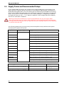
1
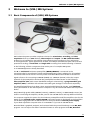
(USB-) ME-Systems Manual Information in this document is subject to change without notice. No part of this document may be reproduced or transmitted without the express written permission of Multi Channel Systems MCS GmbH. While every precaution has been taken in the preparation of this document, the publisher and the author assume no responsibility for errors or omissions, or for damages resulting from the use of information contained in this document or from the use of programs and source code that may accompany it. In no event shall the publisher and the author be liable for any loss of profit or any other commercial damage caused or alleged to have been caused directly or indirectly by this document. © 2011 Multi Channel Systems MCS GmbH. All rights reserved. Printed: 19. 07. 2010 Multi Channel Systems MCS GmbH Aspenhaustraße 21 72770 Reutlingen Germany Fon +49-71 21-90 92 5 - 0 Fax +49-71 21-90 92 5 -11 [email protected] www.multichannelsystems.com Microsoft and Windows are registered trademarks of Microsoft Corporation. Products that are referred to in this document may be either trademarks and/or registered trademarks of their respective holders and should be noted as such. The publisher and the author make no claim to these trademarks. Table of Contents 1.1 Operator's Obligations 5 1.2 Guarantee and Liability 5 1.3 Important Safety Advice 6 2.1 Basic Components of ME-Systems 9 2.2 System Configurations and Optional Components 10 2.2.1 Single Components for Standard Systems 11 2.2.2 ME Data Acquisition 11 2.2.3 Miniature Preamplifiers (MPA) 13 2.2.4 Filter Amplifiers with Fixed Gain (FA) 13 2.2.5 Programmable Gain Amplifiers 13 2.3 Accessories 14 2.4 Add-ons for Stimulation 14 2.5 Setting up the ME-System 15 2.6 Supply Power and Recommended Setups 16 2.7 Signal Amplification and Filters 17 2.8 Data Acquisition 18 2.8.1 MC_Card Hardware 18 2.8.2 DC Offset Correction 18 2.8.3 Sampling Rate 19 2.8.4 Software Package 20 2.9 Digital Input / Output, System Synchronization 21 2.9.1 Triggering the MC_Card and MC_Rack 21 2.9.2 Custom Switch for "Remote-Controlling" of the MC_Card 21 2.9.3 Triggering other Instruments by the MC_Card 22 3.1 About Troubleshooting 23 3.2 Triggering / Digital Input does not work 23 5.1 Amplifiers 27 5.2 ME-Sytems 28 5.3 Accessories 29 5.4 Add-ons for stimulation 30 5.5 Spare parts 30 5.6 Multielectrode Arrays 31 Important Information and Instructions 1 Important Information and Instructions 1.1 Operator's Obligations The operator is obliged to allow only persons to work on the device, who are familiar with the safety at work and accident prevention regulations and have been instructed how to use the device; are professionally qualified or have specialist knowledge and training and have received instruction in the use of the device; have read and understood the chapter on safety and the warning instructions in this manual and confirmed this with their signature. It must be monitored at regular intervals that the operating personnel are working safely. Personnel still undergoing training may only work on the device under the supervision of an experienced person. 1.2 Guarantee and Liability The General conditions of sale and delivery of Multi Channel Systems MCS GmbH always apply. The operator will receive these no later than on conclusion of the contract. Multi Channel Systems MCS GmbH makes no Guarantee as to the accuracy of any and all tests and data generated by the use of the device or the software. It is up to the user to use good laboratory practice to establish the validity of his findings. Guarantee and liability claims in the event of injury or material damage are excluded when they are the result of one of the following. Improper use of the device. Improper installation, commissioning, operation or maintenance of the device. Operating the device when the safety and protective devices are defective and/or inoperable. Non-observance of the instructions in the manual with regard to transport, storage, installation, commissioning, operation or maintenance of the device. Unauthorized structural alterations to the device. Unauthorized modifications to the system settings. Inadequate monitoring of device components subject to wear. Improperly executed and unauthorized repairs. Unauthorized opening of the device or its components. Catastrophic events due to the effect of foreign bodies or acts of God. 5 ME-System Manual 1.3 Important Safety Advice Warning: ME-/MEA-Systems include several instruments as individual components. Each instrument is shipped with a separate manual. The information in the individual manuals fully apply to the complete system. This manual is only to be understood as an additional information. Read all manuals thoroughly before setting up the system. Warning: Obey always the rules of local regulations and laws. Only qualified personnel should be allowed to perform laboratory work. Work according to good laboratory practice to obtain best results and to minimize risks. The product has been built to the state of the art and in accordance with recognized safety engineering rules. The device may only be used for its intended purpose; be used when in a perfect condition. Improper use could lead to serious, even fatal injuries to the user or third parties and damage to the device itself or other material damage. Warning: The devices and the software are not intended for medical uses and must not be used on humans. Malfunctions which could impair safety should be rectified immediately. High Voltage Electrical cords must be properly laid and installed. The length and quality of the cords must be in accordance with local provisions. Only qualified technicians may work on the electrical system. It is essential that the accident prevention regulations and those of the employers' liability associations are observed. Each time before starting up, make sure that the mains supply agrees with the specifications of the products. Check the power cords for damage each time the site is changed. Damaged power cords should be replaced immediately and may never be reused. Check the leads for damage. Damaged leads should be replaced immediately and may never be reused. Do not try to insert anything sharp or metallic into the vents or the case of the products. Liquids may cause short circuits or other damage. Keep the devices and the power cords always dry. Do not handle it with wet hands. 6 Important Information and Instructions Electromagnetic compatibility of the MC_Card The MC_Card data acquisition board is only intended for research work in laboratories. It belongs to product class 0 conforming to the European Product Regulations and the CE (Conformité Européenne) marking. The MC_Card complies with all applicable directives specified in the Council Directive for Electromagnetic Compatibility (89/336/EU). Requirements for the installation The MC_Card is only suitable for extra-low voltages and shall be used only as specified. The equipment shall be correctly earthed or connected to ground. The analog inputs should be closed or connected to active signals. Connections to all inputs and outputs shall be made with screened cables specified by Multi Channel Systems. The screen has to be connected to a solid earth or chassis connection. ESD voltages at open lines may cause malfunction during operation. The products shall only be operated from approved power packs (if necessary). 7 Welcome to (USB-) ME-Systems 2 Welcome to (USB-) ME-Systems 2.1 Basic Components of (USB-) ME-Systems Multi Channel Systems provides complete solutions for stimulation, recording, and data acquisition from up to 256 channels, data analysis and export. The ME (multielectrode) product line is intended for extracellular electrophysiological recordings in vivo, and special in vitro applications. Typical applications include, for example simultaneous spike and local field potential recording; or multi-unit and single-unit recording from awake behaving of animals. In the following, all basic components that can be part of a complete ME-System or an USB-ME-System are briefly described. The 8- or 32-channel miniature preamplifier (MPA8I, MPA32I) is connected to the microelectrodes for providing the initial tenfold amplification stage. Adapters for all standard microelectrodes such as acute or chronic probes from NeuroNexus are available as accessories. Signal collectors for connecting 8 x MPA8I (SC8x8) or 2 x MPA32I (SC2x32) collect the output channels of the preamplifiers and send the preamplified raw data stream to the following filter amplifier (FAI) with custom bandwidth and gain. Alternatively, a programmable gain amplifier (PGA) is available with software-selectable gain settings for all channels separately. The amplified and filtered raw data is then acquired and digitized by the MC_Card hardware that is preinstalled on the data acquisition computer or by an external USB based data acquisition device. 68-pin MCS high grade cables C68x3M (3 meters), C68x1M (1 meter), or C68x0.5M (0.5 meter) are used for connecting the amplifier, the MC_Card or the USB-ME device and any additional devices. The computer supplies the power for the miniature preamplifiers and filter amplifiers (not for the PGAs) via the isolated power supply IPS10W. The supply power is distributed to the amplifiers via the MCS high grade cable as well. Please note that you need an external power supply if your data acquisition computer lacks of an IPS10W or if you use an USB-ME device. Recorded data is graphed, analyzed, and reviewed with the powerful and easy-to-use MC_Rack program. You can export the data in standard formats to other programs with MC_DataTool. 9 ME-System Manual (USB-) ME-Systems can be combined with a wide range of MCS products: Amplifiers, stimulators, and various accessories. In addition to the standard ME product line, the USB-ME-FAI-Systems are available as very compact, portable stand-alone solutions for extracellular recordings from 16 and 32 channels. The systems feature an integrated 16- / 32-channel filter amplifier and data acquisition. The digitally converted electrode signals are transmitted to the connected computer via universal serial bus (Full Speed USB 2.0). In USB-ME64- / 128- / 256-Systems the MC_Card hardware is replaced by the external USB-ME64- / 128- / 256- data acquisition device. Analog raw data are digitized and transmitted to any computer via USB High Speed 2.0. 2.2 System Configurations and Optional Components Multi Channel Systems provides several complete standard configurations and custom systems. This chapter will give an overview on different system configurations. Please see also both handouts “Multielectrode Array Systems System Suggestions” and “Multielectrode Array Systems USB-System Suggestions”, which show detailed diagrams of several typical setups. Please note that you have various options for setting up your personal (USB-) ME-System configuration. For more information about the scope of delivery of your system, please see the separate shipping documents. Please see the separate documentation for information on installing and operating the individual components of your (USB-) ME-System. All warnings and safety related information of the separate documents apply and must be regarded. Do not hesitate to contact MCS or your local retailer if you are interested in a particular setup or if you have other questions. 10 Welcome to (USB-) ME-Systems 2.2.1 Single Components for Standard Systems The following components are part of ME standard systems. Please make sure that you have carefully studied the documentation on the single components before setting up your system. All manuals can be found on the installation volume shipped with the system. Updated versions can also be downloaded from the MCS web site. Web link to the manual download page on www.multichannelsystems.com Product Manual / Reference 8- or 32-channel 10x miniature preamplifiers (MPA8I or MPA8I / PA32I Manual, SC8x8/SC2x32 MPA32I) with signal collectors (SC8x8 or SC2x32) data sheet Filter amplifiers (FA) or programmable gain amplifiers (PGA) with custom bandwidth and gain settings (PGA with flexibly adjustable gain from 10 to 5000) FA Manual, PGA Manual Data acquisition computer with MC_Card and integrated isolated power supply IPS10W or external power supply PS40W USB-ME64-System, USB-ME128-System, USB-ME256-System ME-System Manual PS40W Manual USB-ME64-System Manual, USB-ME128-System Manual, USB-ME256-System Manual Data acquisition and analysis software MC_Rack and MC_DataTool MC_Rack Manual / Help, MC_Rack Tutorial Complete ME-System / Setup ME-System Manual, Multielectrode Array Systems, System Suggestions, Multielectrode Array Systems, USB-System Suggestions Complete USB-ME-System / Setup 2.2.2 ME Data Acquisition The basic ME data acquisition system includes a data acquisition computer and a software package. Analog input signals are acquired from the data source and digitized by the MC_Card that is preinstalled on the data acquisition computer. The ME data acquisition system is available in different channel configurations: ME16, ME32, ME64, and ME128 with 16, 32, 64, and 128 analog channels, respectively. The MC_Card provides the option to use a 16-bit digital (TTL) channel instead of one of the analog data acquisition channels. You can use the digital TTL inputs, for example, for synchronizing stimulation and recording, or for synchronizing the ME-System with other systems, video tracking, for example. The digital TTL outputs can be used for triggering other systems and instruments, for example, for applying a feedback. The standard scope of delivery includes a three BNC input slot for connecting three input bits of the digital channel. If you need more input bits or output bits for more advanced setups, MCS provides a Digital IN / OUT Extension as an accessory, with 32 BNC connectors for connecting all 16 input and output bits to separate TTL sources / inputs. 11 ME-System Manual 2.2.3 USB-ME Data Acquisition The basic USB based data acquisition system includes an USB-ME data acquisition device and a software package. Analog input signals are acquired from the data source and digitized by the USB-ME device. The digitized data are transmitted to any data acquisition computer via USB High Speed 2.0. The USB-ME data acquisition system is available in different channel configurations: USB-ME64, USB-ME128, and USB-ME256 with 64, 128 and 256 analog channels, respectively. 2.2.4 USB-ME-FAI-Systems The USB-ME16-FAI-System is a very compact, portable stand-alone solution for extracellular recordings from 16 channels. The system features an integrated 16-channel filter amplifier and data acquisition. The digitally converted electrode signals are transmitted to the connected computer via universal serial bus (Full Speed USB 2.0). Thus, it is possible to use any computer as a data acquisition computer, for example, a laptop. The size of the complete system is so small, it easily fits into a laptop bag together with the computer. Interference of computer components with computer components are excluded. Please see the USB-ME16-FAI-System Manual for more information. The USB-ME32-FAI-System is a very compact, portable stand-alone solutions for extracellular recordings from 32 channels. The system features an integrated 32-channel filter amplifier and data acquisition. The digitally converted electrode signals are transmitted to the connected computer via universal serial bus (Full Speed USB 2.0). Thus, it is possible to use any computer as a data acquisition computer, for example, a laptop. The size of the complete system is so small, it easily fits into a laptop bag together with the computer. Interference of computer components with computer components are excluded. Please see the USB-ME32-FAI-System Manual for more information. 12 Welcome to (USB-) ME-Systems 2.2.5 Miniature Preamplifiers (MPA) The miniature head stage preamplifiers MPA can be connected directly to the microelectrodes in the test model to provide the first amplification stage of 10. Adaptors for standard multielectrodes such as NeuroNexus probes are available. The signal channels can be collected and sent to a signal collector, which connects to the amplifier. The miniature preamplifiers small size allows easy placement. The metal housing prevents the amplifier from picking up external noise. Miniature preamplifiers are available for 8 and 32 electrodes (MPA8I, MPA32I). Both versions are type I amplifiers, that is, they include a common ground and one reference electrode input. Please see “Filter Amplifiers with Fixed Gain” for more information on I type amplifiers. 2.2.6 Filter Amplifiers with Fixed Gain (FA) Raw data from electrodes or from the preamplifier can be amplified by filter amplifiers with fixed gain. Amplifiers with 4, 8, 16, 32, 48, and 64 input channels are available with two different input types (S or I). Amplifiers can be ordered with any gain and bandwidth configurations by the user's choice. For example, typical pass bands would be 1 to 300 Hz for recording field potentials and 300 to 3000 Hz for recording action potentials. It is also possible to use a broadband amplifier and filter the data with the digital filter of the MC_Rack program. Input type S / Single ended inputs Amplifiers with input type S have single ended inputs. All signals are measured with respect to the amplifier’s ground. The signal source's ground and the amplifier's ground should have the same value for obtaining good results. Input type I / Subtracts reference from input voltage An amplifier with input type I includes a common ground and a common indifferent reference electrode input. The reference electrode is ideally identical to the recording electrodes and placed into a comparable but inactive area or tissue. Background or noise signals that are picked up by both the reference electrode and the recording electrodes are removed. 2.2.5 Programmable Gain Amplifiers (PGA) Raw data from the preamplifier is amplified by the programmable gain amplifier, which is basically an S type filter amplifier, but in addition, the gain can be flexibly adjusted from 10 to 5000 with the user-friendly program PGA-Control. Standard versions with 16, 32, and 64 input and output channels are available. Also, special versions are available that feature two different pass bands. Signals are split and the two pass bands are sent to two separate output channels. For 16 input and 32 output channels, or 32 input and 64 output channels, respectively. These amplifiers are perfect for recording signals with different frequencies. Programmable gain amplifiers can be ordered with any bandwidth configuration by the user's choice. 13 ME-System Manual 2.3 Accessories MCS provides a wide range of accessories that will make your (USB-) ME-System setup even more efficient and convenient to use. All accessories are perfect for use with MCS products, but are easily adaptable to custom systems as well. Some accessories are included in complete systems, other have to be ordered separately. Signal Collectors (SC8x8, SC2x32) for collecting the channels from the miniature preamplifiers and leading them to the amplifier via a 68-pin MCS standard cable. Versions for connecting 8 x MPA8I or 2 x MPA32I are available (SC8x8 and SC2x32, respectively). The SC8x8 is also available as a special version with blanking circuit (SC8x8BC): A blanking signal transiently grounds the recording electrodes during the stimulus, thus preventing stimulus artifacts. Signal Dividers (SD16, SD32, SD64) allow the user to connect any channel via BNC connector to an external device, for example, an oscilloscope, without interfering with the data acquisition. Digital IN / OUT Extension (Di/o) for connecting other devices to single digital input and output channels of the MC_Card via BNC connectors (up to 16 inputs and 16 outputs), for example, for synchronizing stimulation and recording, or for applying feedback. Signal Grounding Unit (GND64) for silencing defective electrodes. Single channels can be turned off with small toggle switches. Inputs not in use are grounded. Power Supply (PS40W) for supplying 40 W power (+/– 7 V output voltage) to programmable gain amplifiers, for custom setups that lack an internal power supply, or for other custom applications. 2.3 Add-ons for Stimulation MCS provides general-purpose stimulators like the advanced 4000 series with 2, 4 or 8 channels. The flexible MC_Stimulus II software enables complex stimulus waveforms in current and voltage mode. Waveforms designed in the program or imported from an external file are converted by the STG into pulses, which are sent to the amplifier for stimulating electrodes. Stimulus isolation units are integrated in the STG for each channel. Thus, no additional stimulus isolations units are required. Trigger in- and outputs are available for an exact timing of stimulation and for controlling other instruments by TTL pulses. For example, stimulation and recording can be synchronized with a digital trigger signal (TTL) sent from the Sync Out output of the stimulus generator to the MC_Card or the an USB-ME device via digital inputs. With the SC8x8BC with blanking circuit, stimulus artifacts and amplifier saturation are effectively prevented. 14 Welcome to (USB-) ME-Systems 2.4 Setting up the (USB-) ME-System Warning: Please read the separate manuals of all devices before installation, especially the warnings and safety information. Make sure all devices are switched off before you connect them to the power supply. Damage to the devices and even fatal injuries may result from improper installation or use. See also the documentation (USB-) ME-System Setups detailed diagrams and various setup suggestions. Provide a power supply in the immediate vicinity of the installation site. In the following example setup the MC_Card is used as data acquisition. Please refer to the USB based data acquisition manuals for setting up the USB-ME-Systems. 1. Place all devices on a stable and dry surface, where the air can circulate freely and the devices are not exposed to direct sunlight. 2. Set up the computer. 3. Set up all system components as described in the separate manuals. 4. Connect the MPA8Is to the SC8x8, or the MPA32Is to the SC2x32. Close all unused sockets with ground connectors. 5. Connect the SC8x8 or the SC2x32 to the FA or PGA. 6. Connect the FA or PGA amplifier to the MC_Card (input labeled MC_Card Ch. 01–64) with the 68-pin MCS standard cable C68x3M. 7. If you have a ME128 System, connect a second amplifier with the 68-pin MCS standard cable C68x3M to the input for channels 65–128 labeled MC_CX64 Ch. 65–128. 15 ME-System Manual 2.5 Supply Power and Recommended Setups In the standard ME-FAI-Systems, the isolated power supply IPS10W that is preinstalled on the data acquisition computer delivers the power for the amplifiers (MPA and FA), distributed via 68-pin MCS high grade cable. One of the limiting factors when using the IPS10W is the voltage drop of the 3 m MCS high grade cable. The characteristic resistance of the cable is 0.3 Ohms per meter. This results in a 1 Ohm resistance for a 3 m cable, leading to a voltage drop of 500 mV for a 500 mA current (U = R * I = 1 * 500 mA = 500 mV). As the voltage drop limit is 500 mV, the limit for each cable is ± 500 mA. Warning: Follow the manufacturer’s setup recommendations. Do not use longer cables than recommended. Do not connect other amplifiers or more amplifiers than recommended. A voltage drop exceeding the limit of ± 500 mA can lead to improper behavior of the amplifier, or can even melt the wire! The following tables show you how much power the amplifiers need, and how much power the MCS power supplies will provide. Amplifier Supply voltage Supply current MPA2I ± 3 V to ± 8 V DC < ± 2 mA, typically ± 1 mA MPA8I < ± 6 mA, typically ± 4 mA MPA32I(FLEX) < ± 14 mA, typically ± 9 mA FA8 ± 6 V to ± 9 V DC < ± 40 mA, typically ± 25 mA FA16 < ± 75 mA, typically ± 50 mA FA32 < ± 150 mA, typically± 100 mA FA48 < ± 225 mA, typically ± 150 mA FA64 < ± 300 mA, typically ± 200 mA PGA16 ± 5.7 V to ± 12 V DC 350 mA (positive rail), 110 mA (negative rail) PGA32 550 mA (positive rail), 225 mA (negative rail) PGA64 725 mA (positive rail), 450 mA (negative rail) PGA1632 550 mA (positive rail), 225 mA (negative rail) PGA3264 725 mA (positive rail), 450 mA (negative rail) Power supply Supply voltage Supply current IPS10W (internal power supply) ± 6.3 V ± 10 % max. 1.2 A @ + 6.3 V or – 6.3 V PS40W (external power supply) ± 7 V ± 10 % max. 2.5 A @ ± 7 V 16 Welcome to (USB-) ME-Systems 2.6 Signal Amplification and Filters FA and PGA amplifiers combine a band pass filter and the signal amplification in one instrument. Different filter settings are used to enhance the signal-to-noise ratio. The pass band of the filter amplifier depends on the signal type. It is generally useful to filter the data with a cutoff at the highest signal frequency. For slow signals like field potentials, a bandwidth of 1 to 300 Hz is appropriate. If you like to record fast signals like spikes, a pass band of 300 Hz to 3 kHz is suitable. Cardiac signals have fast and slow components; therefore, you usually need a wider bandwidth of 1 Hz to 3 kHz. Multi Channel Systems MCS GmbH provides custom amplifiers with a bandwidth of your choice, from 0.1 Hz to 10 kHz. Please note that it is often wise to acquire the data with a broadband amplifier and use the digital filter of the MC_Rack program to adjust the pass band. This way, you are much more flexible in designing your experiments. As a further advantage, you can see the original (not filtered) data as well. This is especially important because all filters are known to distort signals. On the other hand, you may need a higher sampling rate to avoid aliasing, and the signal-to-noise ratio is lower. See also the chapter Data Acquisition for more information. Multi Channel Systems also provides amplifiers with a gain of your choice (from 100 to 5000). For large signals (for example, from heart preparations), you need a lower gain to prevent a saturation of the amplifier. Please note that the gain of FAs is a fixed hardware property; and that you cannot change the gain of the amplifier by software controls. The gain of PGAs can be flexibly adjusted for each channel from 10 to 5000. Please note that the ratio of the output signal to the input signal, that is, the gain, is not a fixed parameter for the complete bandwidth. The gain that was specified for the amplifier, for example, 1200, is not fully reached at the borders of the amplifier's pass band. The general rule is, that at the lower and upper limit of the frequency band, the gain is 2 / 2 , that is approximately 70 %, of the full gain. Therefore, you should use a bandwidth that is at a safe distance of the signals of interest. Outside the pass band, the gain decreases with the frequency and finally approaches zero. The low-pass filter properties of the MC_Card will affect the bandwidth of the complete system only slightly. For information on the gain and filters of the amplifiers, please see the appropriate manual. For more information on gain and filters in general, please refer to standard literature or contact your local retailer. 17 ME-System Manual 2.7 Data Acquisition Recording from up to 256 channels is easy with the MC_Card hardware or with USB based data acquisition device and the MC_Rack software. 2.7.1 MC_Card Hardware Important: You need to have installed the latest MC_Card driver to operate the MC_Card, which is usually preinstalled on the data acquisition computer. The installation may be invalid if the MC_Card does not respond. Please contact Multi Channel Systems MCS GmbH if you need the MC_Card Driver and a description of the installation. The MC_Card is an A/D board that converts analog signals in real time into digital data streams at sampling rates of up to 50 kHz for all channels. You will not miss even the fastest signals. You configure the input voltage range from +/- 400 mV to +/- 4V and the sampling rate with the software controls in the MC_Rack program. Please refer to the MC_Rack Help or Manual for more information. Please see the MC_Card data sheet for additional information on the pin layouts and the technical specifications. 2.7.2 USB based Data Acquisition The USB-ME64 / 128 / 256-System are stand-alone solutions for acquiring data from up to 256 channels. They can replace the internal computer hardware MC_Card. The analog input signals are acquired and digitized by the USB-ME-System and the digital electrode signals are transmitted to the connected computer via universal serial bus (High Speed USB 2.0). Thus, it is possible to use any computer for data processing. Please refer to the USB-ME64- / 128- / 256-System manuals respectively. 2.7.3 DC Offset Correction An offset correction is generally not necessary, because the intrinsic DC offsets of the MCS amplifier outputs and the MC_Card are very low in comparison to the signals of interest. The maximum DC offset of the MC_Card is +/– 2 mV. For example, with a total gain of 1000, this results in a maximum offset of only 2 μV (+/– 2 mV divided by 1000) for the input signals. You can use the MC_Rack offset correction feature to remove even this low offset and reset all channels to zero. Please refer to the MC_Rack Help or Manual for more information. Note: If you observe a large offset on any channel(s), you should contact your local retailer for troubleshooting. The offset correction is not intended for removing large offsets, because the offset correction will decrease the input voltage range. 18 Welcome to (USB-) ME-Systems 2.7.4 Sampling Rate It is recommended to adjust the sampling rate according to your signals, because the higher the sampling rate, the bigger the file size will be. As a rule of thumb, the sampling rate should equal five times the highest signal frequency for a good digitized representation of the continuous analog signals. If the sampling rate is too low, you will miss signals and / or see artifacts. Considering the preceding statements about filtering data, you would for example use a 5 kHz sampling rate when using an amplifier with a cutoff frequency of 1 kHz. Please note that if you use a broadband amplifier and a digital filter, you may have to use a even higher sampling rate. This is the case because the whole amplifier bandwidth is recorded and then high frequency noise is removed with a digital Low Pass filter after recording. Frequencies (noise) that are above half the sampling rate (for example above 2.5 kHz at a 5 kHz sampling rate) will be transformed into lower frequencies. This is called aliasing. This low frequency noise passes the digital Low Pass filter and increases your noise level. According to the Nyquist-Shannon sampling theorem, the sampling rate should equal twice the bandwidth of the analog (hardware) Low Pass filter. The 1/2 bandwidth frequency is also called Nyquist frequency. You may ignore this if saving hard disk space is more important for your application than the noise level. Aliasing Note: The sampling frequency should be at least five times the highest signal frequency and at least twice the bandwidth of the filter amplifier. Example: You have a broadband filter amplifier with a bandwidth of 0.1 Hz to 10 kHz. The expected signals have a maximum frequency of 1 kHz. Therefore, you want to filter the data with a digital low pass filter and a cutoff frequency of 1 kHz. A sampling rate of 5 kHz (five times the highest signal frequency) would be required for faithfully reproducing the signals, but you should use a sampling rate of at least 20 kHz because the sampling rate should equal twice the bandwidth of the analog filter, regardless of the digital filter properties. If you had an amplifier with a cutoff frequency of 1 kHz instead, no digital filter would be required, and a sampling rate of 5 kHz would be enough. 19 ME-System Manual 2.7.5 Software Package With the high-performance data acquisition and analysis program MC_Rack, you can flexibly manage all data streams. For example, you can display the raw data of all channels while recording only the raw data of the channels of interest and the extracted parameters of all channels. This saves computer performance and hard disk space. MC_Rack is not limited to special applications, but can be flexibly adapted to a wide range of applications. Unlimited software licenses and support come free with the system, and free software updates lower the costs as well. The *.mcd data format is support by several third party programs for further analysis. You can also easily convert recorded data to universal formats such as ASCII with the MC_DataTool program. 20 Welcome to (USB-) ME-Systems 2.8 Digital Input / Output, System Synchronization TTL stands for Transistor-Transistor Logic. A TTL pulse is defined as a digital signal for communication between two devices. A voltage between 0 V and 0.8 V is considered as a logical state of 0 (LOW), and a voltage between 2 V and 5 V means 1 (HIGH). Warning: A voltage that is higher than +5 Volts or lower than 0 Volts, that is, a negative voltage, applied to the digital input would destroy the MC_Card. Make sure that you apply only TTL pulses (0 to 5 V) to the digital inputs. Important: Three BNC connectors for the digital input bits 0 to 2 are included in the standard configurations of the ME-System with MC_Card. If you want to use more bits of the 16 bit input channel or the 16 bit output channel, you have to order a Digital IN / OUT Extension separately. You can also upgrade your system with the extension later. Please contact your local retailer for details. In USB based data acquisition systems, the 16 bit Digital IN / OUT connector is available serially. 2.8.1 Triggering the Hardware and MC_Rack The digital input accepts TTL pulses. This feature can be used for triggering the MC_Card and USB based data acquisition devices and MC_Rack, for example, for synchronizing stimulation and data acquisition. For example, you can connect the SyncOut of a STG (stimulus generator) to one of the digital input bits. If you use only one instrument for triggering, connect it to bit 0. In MC_Rack, add a Trigger Detector to your virtual rack, and select the Digital Data D1 input stream as the Trigger. Select the appropriate logical state (generally HIGH) for triggering. Mask all unused bits. The standard settings of the Trigger Detector are for using bit 0. Please see the documentation on the Trigger Detector instrument and on triggered data in the MC_Rack Help or Manual for more details. Important: It is recommended to set the duration of a TTL pulse to at least 200 μs. Shorter pulses may be ignored by the hardware. Please mask unused (not connected) digital input channels in the MC_Rack program to ignore undefined states of the open inputs that can cause unwanted trigger events. Please see the MC_Rack Manual for more details. 2.8.2 Custom Switch for "Remote-Controlling" of the MC_Card You can connect any device that produces TTL outputs, for example a switch, to one of the digital input bits of the MC_Card. This means you can use a trigger for remote controlling the recording with MC_Rack, or for synchronizing systems, if the data acquisition computer is not within reach during an experiment. You can define the time length of the cutouts that are recorded around the trigger event in MC_Rack. Please note that it is not possible to start the recording of a continuous data file with MC_Rack on a trigger, but you can start a new data file on the trigger event (select the Recorder option Create New File On Trigger). The following picture shows a suggested circuit diagram for a switch used for remote controlling. The resistor and capacitor work as a low-pass filter on the TTL signal and are necessary to reduce ringing of the signal. 21 ME-System Manual 2.8.3 Triggering other Instruments by the Digital OUT The digital output of the MC_Card and the USB based data acquisition sends 20 ms TTL pulses (0 V = LOW and 5 V = HIGH). This feature can be used to apply a feedback triggered by a signal or a parameter stream. For example, you can connect the Trigger In of a STG (stimulus generator) to the digital output via Digital IN / OUT Extension (MC_Card) or Digital IN / OUT connector (USB based data acquisition). You can also use the digital output for a synchronization of the ME-System with other systems, for example, for video tracking (provided that the other system of choice is able to receive TTL pulses). Please see the documentation on the Digital Output instrument in the MC_Rack Help or Manual for more details. 22 Troubleshooting 3 Troubleshooting 3.1 About Troubleshooting The following hints are provided to solve special problems that have been reported by users. Most problems occur seldom and only under specific circumstances. Please check the mentioned possible causes carefully when you have any trouble with the product. In most cases, it is only a minor problem that can be easily avoided or solved. If the problem persists, please contact your local retailer. The highly qualified staff will be glad to help you. Please inform your local retailer as well, if other problems that are not mentioned in this documentation occur, even if you have solved the problem on your own. This helps other users, and it helps MCS to optimize the instrument and the documentation. Please pay attention to the safety and service information in the separate manuals of the related products and in the software help. Multi Channel Systems has put all effort into making the product fully stable and reliable, but like all high-performance products, it has to be handled with care. 3.2 Triggering / Digital Input does not work You have connected a TTL source (for example, the SyncOut of a stimulus generator) to the digital input of the MC_Card or the USB based data acquisition, and configured the virtual rack in MC_Rack for triggering displays or data acquisition by the TTL source, but you do not see any sweeps. Possible causes: ? The TTL source does not generate true TTL signals (5 V), or the TTL pulse is shorter than 200 μs. The hardware can only accept TTL signals (CMOS 5 V TTL level) as a digital input stream. A minimum TTL pulse of 200 μs is recommended. Otherwise, a detection of the trigger by the hardware is not guaranteed. ? The software settings for the Trigger Detector do not match with the hardware configuration. In MC_Rack, add a Trigger Detector to your virtual rack, and select the Digital Data D1 input stream as the Trigger. Check the digital inputs and make sure that the same bit input that is connected is selected in the software. (The standard settings of the Trigger Detector are for using bit 0). Mask all unused bits. Select the appropriate logical state (generally HIGH) for triggering. Please see the MC_Rack Help or Manual for more details. 23 Contact Information 4 Contact Information Local retailer Please see the list of official MCS distributors on the MCS web site. User forum The Multi Channel Systems User Forum provides an excellent opportunity for you to exchange your experience or thoughts with other users worldwide. http://multichannelsystems.forumieren.de/index.htm Mailing List If you have subscribed to the mailing list, you will be automatically informed about new software releases, upcoming events, and other news on the products of MCS. You can subscribe to the list on the contact form of the MCS web site. www.multichannelsystems.com 25 Ordering Information 5 Ordering Information Please contact your local retailer for pricing and ordering information. 5.1 Amplifiers Product Product Number Description Miniature preamplifier with 2 electrode inputs MPA2I Miniature preamplifier with 8 electrode inputs MPA8I Small sized and light weight headstage with common ground and additional indifferent reference electrode input, input type I, gain = 10 Miniature preamplifier with 32 electrode inputs MPA32I Miniature preamplifier with 32 electrode inputs for use with FlexMEAs MPA32IFLEX Filter amplifiers with 4, 8, 16, 32, 48, or 64 channels and input type S or I FANNX NN is the total number of channels, X is the input type (S or I), with custom gain and bandwidth Amplifier with programmable gain, 16 channels PGA16 Gain programmable from 10 to 5000, with custom bandwidth Amplifier with programmable gain, 32 channels PGA32 Amplifier with programmable gain, 64 channels PGA64 Amplifier with programmable gain, 16 input and 32 output channels PGA1632 Amplifier with programmable gain, 32 input and 64 output channels PGA3264 Gain programmable from 10 to 5000, with two different custom pass bands 27 ME-System Manual 5.2 ME-Systems Product Product Number Description Data acquisition system with 16 analog channels ME16 System Data acquisition system with 32 analog channels ME32 System Complete with data acquisition computer with MC_Card and IPS10W, and software package Data acquisition system with 64 analog channels ME64 System Data acquisition system with 128 analog channels ME128 System USB-ME recording system with 16 analog channels and filter amplifier with fixed gain USB-ME16-FAI System Stand-alone system for extracellular recordings, complete with 2 x MPA8I, integrated FA16I, integrated 16 channel data acquisition, USB 2.0 data transfer to computer, and software package USB-ME recording system with 32 analog channels and filter amplifier with fixed gain USB-ME32-FAI System Stand-alone system for extracellular recordings, complete with 4 x MPA8I, - or - 1x MPA32I, integrated FA32I, integrated 16 channel data acquisition, USB 2.0 data transfer to computer, and software package ME recording system with 16 analog channels and filter amplifier with fixed gain ME16-FA-System Complete with 2 x MPA8I, SC8x8, FA16I, data acquisition computer with MC_Card and IPS10W, and software package ME recording system with 32 analog channels and filter amplifier with fixed gain ME32-FA-System Complete with 2 x MPA32I, SC2x32, FA32I, data acquisition computer with MC_Card and IPS10W, and software package ME recording system with 64 analog channels and filter amplifier with fixed gain ME64-FA-System Complete with 2 x MPA32I, SC2x32, FA64I, data acquisition computer with MC_Card and IPS10W, and software package ME recording system with 128 analog channels and filter amplifier with fixed gain ME128-FA-System Complete with 4 x MPA32I, 2 x SC2x32, 2 x FA64I, data acquisition computer with MC_Card and IPS10W, and software package 28 Ordering Information 5.3 ME recording system with 16 analog channels and filter amplifier with programmable gain ME16-PGA-System Complete with 2 x MPA8I, SC8x8, PGA16, data acquisition computer with MC_Card and IPS10W, and software package ME recording system with 32 analog channels and filter amplifier with programmable gain ME32-PGA-System Complete with 2 x MPA32I, SC2x32, PGA32, data acquisition computer with MC_Card and IPS10W, and software package ME recording system with 64 analog channels and filter amplifier with programmable gain ME64-PGA-System Complete with 2 x MPA32I, SC2x32, PGA64, data acquisition computer with MC_Card and IPS10W, and software package ME recording system with 128 analog channels and filter amplifier with programmable gain ME128-PGA-System Complete with 4 x MPA32I, 2 x SC2x32, 2 x PGA64, data acquisition computer with MC_Card and IPS10W, and software package Accessories Product Product Number Description 32-Channel Cactus Needle Adapter ADPT-CN-32 The 32-Channel Cactus Needle Adapter allows a direct connection of electrodes with cactus needles to a 32-channel miniature preamplifier MPA32I. FlexMEA Adapter ADPT-FM-32 The FlexMEA Adapter allows a direct connection of FlexMEA36 to a 32-channel miniature preamplifier MPA32I. FlexMEA Adapter ADPT-FM-72 The FlexMEA Adapter allows a direct connection of FlexMEA72 to two 32-channel miniature preamplifier MPA32I. 16-Electrode NeuroNexus Probe Adapter ADPT-NN-16 The 16-Electrode Probe Adapter allows a direct connection of 16-Electrode acute probes from NeuroNexus Technologies to two 8-channel miniature preamplifiers MPA8I. 32-Electrode NeuroNexus Probe Adapter ADPT-NN-32 The 32-Electrode Probe Adapter allows a direct connection of 32-Electrode acute probes from NeuroNexus Technologies to a 32-channel miniature preamplifier MPA32I. 64-Electrode NeuroNexus Probe Adapter ADPT-NN-64 The 64-Electrode Probe Adapter allows a direct connection of 64-Electrode acute probes from NeuroNexus Technologies to two 32-channel miniature preamplifiers MPA32I. Signal collector for 8 x MPA8I SC8x8 Collects the 8 channels from each of the up to 8 miniature preamplifiers MPA8I and leads them to the amplifier via a 68-pin MCS standard cable Signal collector for 2 x MPA32I SC2x32 Collects the 32 channels from each of the up to 2 miniature preamplifiers MPA32I and leads them to the amplifier via a 68-pin MCS standard cable Signal collector with blanking circuit for 8 x MPA8I SC8x8BC Collects the 8 channels from each of the up to 8 miniature preamplifiers MPA8I and leads them to the amplifier via a 68-pin MCS standard cable, the voltage outputs are held constant during the TTL blanking signal, stimulus artifacts are avoided 29 ME-System Manual 5.4 5.4 Signal dividers with 16, 32, or 64 channels SD16, SD32, SD64 Placed between amplifier and MC_Card, permits to select any channel, does not interfere with the data acquisition Signal grounding unit GND64 For silencing defective electrodes. Single channels can be switched off with small toggle switches. Inputs not in use are grounded. Isolated power supply with 10 W power and ± 6.3 V output voltage IPS10W Isolated power supply for integration into the data acquisition computer. For supplying power to amplifiers (MEA1060, MPA, FA). Power supply with 40 W power and ± 7 V output voltage PS40W For supplying power to programmable gain amplifiers, for custom setups that lack an internal power supply, or for other custom applications Digital in/out extension Di/o For connecting other devices to single digital input and output channels of the MC_Card via BNC connectors (up to 16 inputs and 16 outputs), for example, for synchronizing stimulation and recording, or for applying feedback. Add-ons for stimulation Product Product Description Number 2-Channel stimulus generator STG4002 4-Channel stimulus generator STG4004 8-Channel stimulus generator STG4008 Advanced stimulus generators for a very wide variety of applications. For software controlled current and voltage-driven electrical stimulation with integrated stimulus isolation unit for each output channel. Operating in Download and Streaming mode (continuous down streaming of pulses from connected computer). MC_Stimulus II software program with advanced features. Spare parts Product Product Number Description 0.5 m 68-pin MCS standard cable C68x0.5M For (USB-) MEA- or ME-Systems 1 m 68-pin MCS standard cable C68x1M 3 m 68-pin MCS standard cable C68x3M Isolated power supply IPS10W 30 Ordering Information 5.5 Multielectrode Arrays A broad range of multielectrode probes are available from several providers. The following are compatible with the miniature preamplifiers from Multi Channel Systems. If you are interested in a particular probe that is not mentioned here, please ask Multi Channel Systems or your local retailer for compatibility. Product Description Flexible microelectrode array (FlexMEA36) With 36 electrodes in total: 32 electrodes arranged in a 6 x 6 grid + 2 reference electrodes + 2 ground electrodes. 30 μm electrode diameter, 300 μm interelectrode distance. TiN electrodes and gold tracks embedded in flexible polyimide foil. Flexible microelectrode array (FlexMEA72) With 72 electrodes in total: 64 electrodes arranged in a 8 x 9 grid + 4 reference electrodes + 4 ground electrodes. 100 μm electrode diameter, 625 to 750 μm interelectrode distance. TiN electrodes and gold tracks embedded in flexible polyimide foil. Flexible microelectrode array (EcoFlexMEA36) With 36 electrodes in total: 32 electrodes arranged in a 6 x 6 grid + 2 reference electrodes + 2 ground electrodes. 50 μm electrode diameter, 300 μm interelectrode distance. Gold electrodes and gold tracks embedded in flexible polyimide (Kapton). Flexible microelectrode array (EcoFlexMEA24) With 24 electrodes in total: 24 electrodes arranged in a 2 x 10 + 4 grid + 2 reference electrodes + 2 ground electrodes. 50 μm electrode diameter, 300 μm interelectrode distance. Gold electrodes and gold tracks embedded in flexible polyimide (Kapton). NeuroNexus probes 16-, 32-, 64-channel silicon probes Supplier Multi Channel Systems MCS GmbH www.multichannel systems.com NeuroNexus Technologies www.neuronexus tech.com 31