1
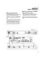
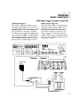
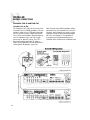
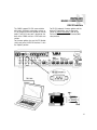
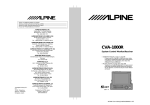
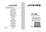
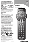
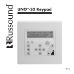
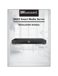
CAA66
Multisource Multiroom
Audio Controller/Amplifier
Installation Manual
IMPORTANT SAFEGUARDS
10.Power Sources - The appliance should be connected to a power supply
only of the type described in the operating instructions or as marked on
the appliance.
11.Grounding or Polarization - Precaution should be taken so that the
grounding or polarization means of an appliance is not defeated.
WARNING: TO REDUCE THE RISK OF FIRE OR ELECTRIC SHOCK,
DO NOT EXPOSE THIS APPLIANCE TO RAIN OR MOISTURE.
CAUTION: TO REDUCE THE RISK OF ELECTRIC SHOCK, DO NOT
REMOVE COVER. NO USER - SERVICEABLE PARTS INSIDE.
REFER SERVICING TO QUALIFIED SERVICE PERSONNEL.
The lightning flash with arrowhead symbol, within an equilateral
triangle, is intended to alert the user to the presence of uninsulated
“dangerous voltage” within the product’s enclosure that may be of
sufficient magnitude to constitute a risk of electric shock to persons.
The exclamation point within an equilateral triangle is intended to
alert the user to the presence of important operating and maintenance (servicing) instructions in the literature accompanying the
appliance.
If you have any questions please call Russound Inc. at
1-800-638-8055 or 603-659-5170.
Safety Instructions:
1. Read Instructions - All the safety and operating instructions should be
read before the appliance is operated.
2. Retain Instructions - The safety and operating instructions should be
retained for future reference.
3. Heed Warnings - All warnings on the appliance in the operating instructions should be adhered to.
4. Follow Instructions - All operating and user instructions should be followed.
13.Cleaning - The appliance should be cleaned only as recommended by
the manufacturer.
14.Non-use Periods - The power cord of the appliance should be
unplugged from the outlet when left unused for a long period of time.
15.Object and Liquid Entry - Care should be taken so that objects do not
fall and liquids are not spilled into the enclosure through the openings.
16.Damage Requiring Service - The appliance should be serviced by qualified service personnel when:
A. The power supply cord or the plug has been damaged; or
B. Objects have fallen, liquid has been spilled into the appliance; or
C. The appliance has been exposed to rain; or
D.The appliance does not appear to operate normally; or
E. The appliance has been dropped or the enclosure is damaged.
17.Servicing - The user should not attempt to service the appliance beyond
that described in the operating instructions. All other servicing should
be referred to qualified service personnel.
Precautions:
1. Power – WARNING: BEFORE TURNING ON THE POWER FOR THE
FIRST TIME, READ THE FOLLOWING SECTION CAREFULLY.
5. Water and Moisture - The appliance should not be used near water; for
example, near a bathtub, washbowl, kitchen sink, laundry tub, in a wet
basement, or near a swimming pool.
2. Do Not Touch The Unit With Wet Hands – Do not handle the unit or
power cord when your hands are wet or damp. If water or any other liquid enters the cabinet, unplug the unit from power immediately and take
it to a qualified service person for inspection.
6. Carts and Stands - The appliance should be
used only with a cart or stand that is recommended by the manufacturer. An appliance
and cart combination should be moved with
care. Quick stops, excessive force and
uneven surfaces may cause the appliance
and cart combination to overturn.
3. Location of Unit – Place the unit in a well-ventilated location. Take special care to provide plenty of ventilation on all sides of the unit especially when it is placed in an audio rack. If ventilation is blocked, the unit
may overheat and malfunction. Do not expose the unit to direct sun
light or heating units as the unit internal components temperature may
rise and shorten the life of the components. Avoid damp and dusty
places.
7. Wall or Ceiling Mounting - The appliance should be mounted to a wall
or ceiling only as recommended by the manufacturer.
4. Care – From time to time you should wipe off the front and side panels
of the cabinet with a soft cloth. Do not use rough material, thinners,
alcohol or other chemical solvents or cloths since this may damage the
finish or remove the panel lettering.
8. Ventilation - The appliance should be situated so that its location or
position does not interfere with its proper ventilation. For example, the
appliance should not be situated on a bed, sofa, rug, or similar surface
that may block the ventilation openings, or placed in a built-in installation, such as a bookcase or cabinet that may impede the flow of air
through the ventilation openings.
9. Heat - The appliance should be situated away from heat sources such
as radiators, heat registers, stoves, or other appliances (including
amplifiers) that produce heat.
2
12.Power Cord Protection - Power supply cords should be routed so that
they are not likely to be walked on or pinched by items placed upon or
against them, paying particular attention to cords at plugs, receptacles,
and the point where they exit from the appliance.
TABLE OF CONTENTS
USER SECTION
Product Introduction ............................................................................................................5
Component Guide
CAA66 Controller ................................................................................................................6
KP6 Keypad........................................................................................................................7
KPL Keypad .......................................................................................................................8
KPSC Keypad......................................................................................................................9
Numeric Entry................................................................................................................9
Prefix and Suffix Commands ...........................................................................................9
SRC1 Remote Control........................................................................................................10
Operation
KP6 User Options Mode ....................................................................................................11
KPL User Options Mode.....................................................................................................12
INSTALLER SECTION
Getting Started
Unpacking ........................................................................................................................13
System Components .........................................................................................................13
Tools Needed....................................................................................................................13
System Installation Considerations......................................................................................13
Connection Tips ................................................................................................................13
Wiring Instructions
Keypad Wiring...................................................................................................................14
Speaker Wiring .................................................................................................................14
Component Guide
CAA66 Controller Front Panel Removal ...............................................................................15
CAA66 Controller Rear Panel .............................................................................................16
KP6 Keypad Update Port ...................................................................................................17
KP6 Keypad Rear Panel ....................................................................................................18
Keypad Installation
KP6 Keypad Installation .....................................................................................................18
Making Connections
Keypad Port Connections...................................................................................................19
Source Audio Input Connections .........................................................................................20
Source IR Connections ......................................................................................................20
RNET Source Audio Connections ........................................................................................21
3
TABLE OF CONTENTS
Common IR Input Connection .............................................................................................22
Speaker Connections ........................................................................................................23
Zone Fixed/Variable Audio Output .......................................................................................24
12VDC Mute Trigger In/Trigger Out ....................................................................................25
Controller Link In/Out ........................................................................................................26
RS-232 Interface ...............................................................................................................27
Initial Hardware Install Test .................................................................................................28
Programming
Programming Center .........................................................................................................29
Controller Setup Mode
Controller ID ...............................................................................................................30
Number of Sources.....................................................................................................31
Factory Initialization.....................................................................................................32
Controller Setup Flow Chart ...........................................................................................33
Source Setup Mode
Source Setup..............................................................................................................34
Command Type Options
RNET Sources..........................................................................................................35
UEI Library ...............................................................................................................36
Learned IR ...............................................................................................................37
Invalid Code .............................................................................................................38
Clear Code ..............................................................................................................39
Source Setup Flow Chart ...............................................................................................40
KPL Setup Flow Chart ....................................................................................................41
KPL Diagnostics Flow Chart ...........................................................................................41
REFERENCE SECTION
Source Names .................................................................................................................42-43
UEI Library Device Codes .................................................................................................44-46
Technical Specifications.........................................................................................................47
Warranty ..............................................................................................................................48
4
INTRODUCTION
Thank you for choosing the Russound® CAA66
controller amplifier to enhance your home with
distributed audio.
The CAA66 caters to homeowners who want
more control over their multiroom systems with
such capabilities as infrared (IR) tools to manage
the system from anywhere in the house. More
source inputs, simplified programming and user
adjustable sound controls make listening to
music throughout the home easier than ever.
Key features include:
• Six sources delivered to any one of six zones
for sharing music throughout the home.
• Simplified programming and control via IR
library and intelligent IR learning capabilities for
quick setup.
• Scalable to 36 zones by connecting multiple
CAA66 units, to make whole-house audio available to larger homes. Your system can grow as
your home grows.
The CAA66 kit ships with a remote control
(SRC1) and elegant keypads (KPL or KP6 models) for home audio one-touch control. From each
keypad, the user can adjust bass, treble, balance
and volume. The system supports multiple keypads per zone for convenient access and
includes an RS232 connection for integration
with home automation systems.
Russound's controller/amplifiers meet the needs
of homeowners who want to experience true
audio fidelity throughout the home. And with the
CAA66, customers have more home audio choices at a cost-effective price.
5
COMPONENT GUIDE
CAA66 FRONT PANEL
The CAA66 front panel consists of a split molded
piece with a removable bottom half. This bottom piece
hides the Programming Center buttons. The power
switch has a push on/push off action with a blue LED
1
2
“power on” indicator to the left which illuminates when
the unit is on. The six zone LEDs light up amber when
the zones are active.
3
4
1
POWER ON/OFF LED - Indicates power on when illuminated
2
MAIN POWER SWITCH - Turns power on and off
3
ROOM LED INDICATORS - Indicate when a room is on (amber) or off (not lit)
4
REMOVABLE COVER - Covers the Programming Center buttons on the controller
The CAA66 front panel bottom half hides the
Programming Center.
The Programming Center is used to perform the controller setup and source setup procedures. These are
explained in detail in the Installers section of this manual. The Programming Center button LEDs light at different rates and in different colors during these proce-
dures to indicate programming steps. It also contains
an IR receiver window for remote control use during
programming.
Note: It is important to properly remove the panel to
prevent damage. See page 15 for complete instructions.
1
1
6
PROGRAMMING CENTER - used to perform the controller setup and
source setup procedures
COMPONENT GUIDE
KP6 KEYPAD
1
8
2
3
7
4
6
5
KP6 Keypad
1
SOURCE NAME - Six clear windows with replaceable source name labels. Current source
selected is backlit amber.
2
VOLUME UP - Raises the volume for the room/adjusts User Menu options.
3
VOLUME DOWN - Lowers the volume for the room/adjusts User Menu options.
4
POWER - Turns zone ON or OFF when pressed once. When OFF, press and hold will turn OFF
all zones. Power button remains lit when OFF if any other zone in the system is ON.
5
IR CONFIRMATION/LOUDNESS LED - Blue LED blinks to confirm IR signal reception, and
remains lit when Loudness feature is enabled.
6
IR RECEIVER - Receives IR signals and passes them to the controller and source equipment.
Also used when the keypad is operated using the CA System remote controls.
7
SOURCE SELECT - Press and release scrolls through the available sources. Press and hold
brings up the USER MENU for Loudness, Bass, Treble, etc.
8
VOLUME LEVEL - Volume level indicator LEDs light up from left to right to indicate volume
level. Also used to indicate user option settings.
7
COMPONENT GUIDE
KPL KEYPAD
9
1
8
2
7
3
6
4
5
KPL Keypad
8
1
LCD PANEL - 5-character amber backlit display shows source name, volume and zone status.
2
VOLUME UP - Raises the volume for the room/adjust User Menu options.
3
VOLUME DOWN - Lowers the volume for the room/adjust User Menu options.
4
POWER - Turns zone ON or OFF when pressed once. When OFF, press and hold will turn OFF
all zones.. Power button remains lit when OFF if any other zone in the system is ON.
5
IR CONFIRMATION/LOUDNESS LED - Blue LED blinks to confirm IR signal reception, and
remains lighted when Loudness feature is enabled.
6
IR RECEIVER - Receives IR signals and passes them to the controller and source equipment.
Also used when the keypad is operated using the CA System remote controls.
7
SOURCE SELECT - Press and release scrolls through the available sources. Press and hold
brings up the USER MENU for Loudness, Bass, Treble, etc.
8
VOLUME LEVEL - 21-segment volume level bars increase from left to right to indicate volume
level/indicates user option settings.
9
SYSTEM INFO - SYS On indicates other active zones and SHARED indicates the selected
source is in use in another zone.
COMPONENT GUIDE
KPSC KEYPAD
KPSC Source Control Keypad
The KPSC keypad connects to a KP6 or KPL keypad to add source control and numeric capability. The amber backlit buttons provide primary
source controls when pressed, such as stop,
play, next, etc.
When the Numeric button is pressed, it becomes
backlit in red, and changes the buttons to numeric entry (0 - 9). Pressing the Numeric button also
sends a Prefix command of “Disc.”
A second press of the Numeric button sends a
Suffix command of “Enter” and puts the keypad
back into the primary control mode. If the button
is not pressed the second time, a 3-second time
out will send the Suffix command and exit
Numeric mode.
The F1 and F2 favorite buttons are programmed
by a press and hold. They save current input and
volume level settings for recall, and can be overwritten with another press and hold.
4
1
1
2
2
3
KPSC Keypad
1
PRIMARY SOURCE CONTROLS - Functions on outer edge of buttons are default or normal
operation for each selected source. These include play, stop, forward, back, pause, etc.
2
FAVORITES - Set and recall two favorite settings of source and volume.
3
NUMERIC VALUE SHIFT - Press to shift buttons to numeric control or entry. Also issues
Prefix command “Disc” and Suffix command “Enter”
4
NUMERIC CONTROLS - Once numeric control is initiated, the primary control buttons now
represent the numeric value when pressed (0-9).
9
COMPONENT GUIDE
SRC1 SYSTEM REMOTE CONTROL
1
POWER - Turns on or off selected zone.
2
NUMERIC INPUT - Number buttons for direct
input of frequency, channel, etc.
3
VOLUME UP/DOWN - Raises or lowers the volume in the zone.
4
MUTE - Mutes/unmutes zone audio output.
5
INFO - Displays current channel and program
information.
6
CURSOR KEYS - Moves the cursor in the program guide and menu screens.
7
OK - Chooses the highlighted menu option.
Performs “Enter” function for devices.
8
EXIT - Exits out of the selected component’s
menu or guide.
9
TRANSPORT KEYS - Controls components (Play,
Pause, Stop, Forward, etc.).
10
PAGE UP/DOWN - For use with cable or satellite
boxes.
11
DISC - Directly selects a disc using Numeric IR.
12
SOURCE KEYS - Selects specific sources.
13
FAVORITES - Selects and saves favorite presets.
14
GUIDE - Displays the program guide.
15
MENU - Accesses the menu of the selected
component.
16
CHANNEL UP/DOWN - Incrementally scrolls
through channels or tuned stations.
17
LAST - Recalls the last channel or page back one
screen in the main menu.
18
INPUT - Switches sources on zone keypad.
1
2
18
17
16
3
4
15
5
6
7
14
8
9
10
13
11
12
10
OPERATION
USER OPTIONS SETTINGS
KP6 Keypad User Options Mode Operation
Source window blinks to indicate the
option that is ready for adjustment
Bass
Treble
Balance
Turn On
Volume
Option
setting level
Press and
hold Source
button to
enter or exit
User Options
Mode
Press Volume
Up or Down
buttons to
adjust setting
Blue LED will blink to
indicate Loudness is
ready for adjustment
KP6 User Options Mode
The User Options Mode allows the user to adjust the
audio properties of a particular zone. The audio features that can be adjusted are: Bass, Treble, Balance,
Turn On Volume and Loudness. The top four Source
windows and the blue LED blink to indicate the option
is ready for adjustment.
To enter the User Options Mode, press and hold the
Source button when the zone is on. A press and hold
of the Source button (or a 9-second timeout) returns
the keypad to regular operation.
The top left (Source 1) button will temporarily blink to
indicate “Bass” is ready for adjustment. Subsequent
presses of the Source button toggle through Treble
(Source 2), Balance (Source 3), Turn On Volume
(Source 4) and Loudness (blue LED).
Press Source
button to
select option
Once an option is selected, the Volume Up/Down buttons are used to adjust settings. The volume indicator
LEDs temporarily light to show the option setting.
Setting Loudness
In User Option Mode, the blue LED will blink rapidly
when Loudness is selected for adjustment. To turn
Loudness ON, press the Volume Up or Down button
once. The blue LED lights solid then blinks again. To
turn Loudness OFF, press Volume Up or Down once.
The blue LED goes dark for a moment, then blinks
again.
When the keypad is in operation, the blue LED lights
solid when Loudness is activated.
11
OPERATION
USER OPTIONS SETTINGS
KPL Keypad User Options Mode Operation
Press and
hold Source
button to
enter or exit
User Options
Mode
Press Volume
Up or Down
buttons to
adjust setting
Press Source
button to
select option
Blue LED will blink to
indicate Loudness is
ready for adjustment
KPL User Options Mode
Options and Settings
The User Options Mode allows the user to adjust the
audio properties of a particular zone. The audio features that can be adjusted are: Bass, Treble, Balance,
Turn On Volume and Loudness.
1. Bass: -10 < Bass:Flat > +10
To enter the User Options mode, press and hold the
Source button when the zone is on. Press and hold the
Source button again (or a 9-second timeout) returns
the keypad to regular operation.
The first option name (Bass) appears on the display to
indicate it is ready for adjustment. Subsequent presses of the Source button toggle through Treble,
Loudness, Balance, and Turn On Volume.
Once an option is selected, the Volume Up/Down buttons are used to adjust settings. The volume indicator
bars indicate the option setting, along with setting
numbers displayed on the LCD.
12
2. Treb (Treble): -10 < Treble:Flat > +10
3. Loud (Loudness) (more bass, fuller sound): On or
Off (When Loudness is turned on, the blue LED lights
solid)
4. Bal (Balance): Left 10 < Center > Right 10
5. OnVol (Turn on Volume) (default room volume level):
0 to 100 (in steps of 2)
INSTALLER
GETTING STARTED
Unpacking the System Components
• Keep the original carton and packing materials
for future shipment or storage.
System Installation Considerations
There are several factors to consider before
installing the Russound CAA66 system:
• Check for any visible signs of damage. If you
encounter any concealed damage, consult your
Russound dealer before proceeding to install the
unit.
• What are the intended listening zones?
• Retain the sales receipt as it establishes the
duration of the limited warranty and provides
information for insurance purposes.
• From where in each zone will the user prefer
to control the system? Where will the keypads
be located? Where will the speakers be located?
CAA66 System Components:
• 6 (six) KP6 or KPL Keypads
• Where will the source equipment be located?
The CAA66 must have proper ventilation above
and below for air circulation and heat dissipation.
A rack-mount location may require fans and vents.
• 1 (one) SRC1 System Remote Control
Connection Tips
• 6 (six) 845.1 Micro Emitters
• It is recommended that the CAA66 and the
source equipment be plugged into a dedicated
20-amp circuit with an isolated ground. A power
line conditioner can reduce interference
problems caused by noise found in some electrical systems.
• 1 (one) CAA66 Controller/Amplifier
Tools needed for installation:
• Drill with a 1/2” x 6” drill bit
• Keyhole saw
• Flat head screwdriver (medium size)
• Phillips Screwdriver (cordless recommended)
• 110 punchdown tool (included)
• Modular RJ-45 crimper and connectors
• Pair of diagonal cutters or wire strippers
• What system options and accessories might
be required for features such as local sources,
etc.?
• Disconnect all live power cords before making
connections to the controller.
• Verify that all connections and polarity are
correct.
• Stud finder
• Keep all power cords away from all signal
cables to prevent humming from induced noise.
• Steel wire fish tape
• Choose reliable signal cables/patch cords.
• Cable staples
• Label all wires with room location at both ends
of the wire.
• Single-gang electrical work boxes
13
INSTALLER
WIRING INSTRUCTIONS
RJ-45 Connections
The CAT-5 T568A wiring standard shown on
the right is used for the RJ-45 terminations.
Keypad Wiring
For the KP6 or KPL keypad, the following connections are used to terminate the CAT-5 wire to
the 110 punchdown on the keypad:
CAT-5 WIRE COLOR
TYPE
Brown. . . . . . . . . . . . . . . . . . . . . +12V
• Confirm ahead of time that you can drill an
outlet hole easily and in an unobtrusive spot
to connect wires with the CAA66.
• Label wires with keypad and room location.
This simplifies CAA66 hook-up once the keypads and speakers are installed.
Brown/White. . . . . . . . . . . . . . . . +12V
Green . . . . . . . . . . . . . . . . . . . Ground
Speaker Wiring
Green/White . . . . . . . . . . . . . Status In
Standard 16-gauge 4-conductor stranded speaker wire can be run up to to 125 feet; 14-gauge
wire can be run up to 250 feet.
Orange . . . . . . . . . . . . . . . . . . Ground
Orange/White . . . . . . . . . . . . . . IR Out
Blue. . . . . . . . . . . . . . . . . . . . . COM A
Blue/White. . . . . . . . . . . . . . . . COM B
• To determine the amount of CAT-5 wire
required for the system installation, first
decide how many keypads will be used, then
determine the distance between each intended keypad location to the planned CAA66
location. The maximum recommended wire
run length is 250 feet for each KP6 or KPL
keypad.
• Make sure that the entire wire path
between keypads and CAA66 is clear and
not obstructed by a floor ceiling joist, or
masonry wall which can’t be drilled through.
14
When running wire, pay particular attention to
the following areas:
• Avoid locations concealing pipes, heating
ducts and AC wiring in the general vicinity.
• Avoid running wires close to house electrical wiring for any distance. If you have to run
them parallel, make sure to space the wires
at least two feet from the AC line.
INSTALLER
COMPONENT GUIDE
Controller Front Panel Removal
Front Panel Removal
The CAA66 front panel removable bottom half hides
the Programming Center. It is important to follow the
proper removal process to remove the panel without
damage.
To remove the panel, you must be able to access the
slots located underneath the front of the controller.
Place a flat screwdriver blade in the bottom
slot on the left and
right between the
cover and the controller. Twist the blade
to loosen the cover
from its catches.
this may require moving it until the front edge hangs
clear of the shelf.
Place a flat screwdriver blade in the bottom slot on
the left and right between the cover and the controller.
Twist the blade, then lift the bottom panel up and off.
Grasp the panel on
each side and gently
lift the panel up and
off.
Panel
removed
from
controller
15
INSTALLER
COMPONENT GUIDE
Controller Back Panel
2
1
15
16
4
3
14
5
13
6
12 11
7
10
8
9
1
CONTROLLER LINK IN AND LINK OUT - Links multiple CAA66 controllers and peripherals.
2
RS-232 INTERFACE - The RS-232 Interface allows the zones to be controlled by PC or other
devices that have an RS-232 Interface, allows for firmware updates and programming.
3
CPU UPDATE SWITCH - For firmware updates.
4
KEYPAD PORTS - One KP6/KPL Keypad Port for each of the six CAA66 Zones.
5
MUTE 12VDC TRIGGER IN - Applying 12VDC to the Mute 12VDC Trigger In jack will mute audio
for assigned CAA66 Zones.
6
12VDC TRIGGER OUT - 12VDC 100mA Trigger Out turns on when any zone is on, and turns off
5 minutes after the last zone is turned off.
7
AC-240V/AC-110V Switch - Switches A/C input voltage between 240VAC and 110VAC.
8
FUSE HOLDER - Holds a replaceable fuse for A/C input connection:
110VAC operation - F3A H 250V; 240VAC operation, T1.25A H 250V.
9
AC 120/240 INPUT - Grounded 3-terminal plug detachable power cord connection.
10
ZONE OUTPUTS - Detachable color-coded modular 8-ohm speaker connectors for each zone.
11
AUDIO OUTPUT - Audio line level output.
12
FIXED/VARIABLE SWITCH - Change line out between fixed and variable output.
13
COMMON IR OUTPUT - Output jack passes all IR signals from all keypads.
14
SOURCE IR OUTPUTS - Six source-specific IR Output jacks allow IR control of source equipment.
15
SOURCE INPUTS - Six pair of Audio Line Level input connections for CAA66 source components.
INSTALLER
COMPONENT GUIDE
Keypad Update Port
The KPSC 12-pin header and the update jumper for the KP6 (and KPL) are located on the right side
of the keypad when facing front. These are covered when a trim plate is installed.
Note: The update pins on the KP6 are accessed from the side when the keypad is not installed.
3
1
OS UPDATE/RUN JUMPER -The pins are
jumpered when performing a firmware
update on the keypad. The jumper is
removed during normal operation.
2
KPSC PORT - 12-pin header for connection to KPSC source control keypad.
3
OS UPDATE PORT - Used to update the
KP6 and KPL keypad operating system
firmware. If an update is released, it will
be available online through the
Document Center on
www.russound.com. Look in the
“Firmware and Downloads” section under
Multi-Zone product type. The Advanced
Programming Cable is available from
Russound, Part #2500-521065.
1
2
KP6 Front View
3
KP6 Top View
1
Jumpered
pins
KP6 Side View
17
INSTALLER
COMPONENT GUIDE
Keypad Rear Panel and Installation
CAT-5 to KP6/KPL Connection
The KP6/KPL keypad uses a 110punchdown terminal on the back
panel to provide simple installation
and a strong connection for CAT-5
cable’s eight conductors.
Punchdown terminals require the
use of a punchdown tool. Attach the
CAT-5 cable to the 110-punchdown
terminal on the KP6 keypad as
shown, matching the conductor colors to the connection color guide.
The keypad will not operate properly
if the terminations deviate from the
required connection order.
Take care when using an impact 110
punchdown tool, as this may overspread the contact points. Use of the
impact tool may propel stray bits of
wire and jacket into the keypad’s chassis and possibly cause a short in the
circuitry. Gently shake or blow air
through the keypad chassis to remove
stray wire before the keypad is
installed into the junction box.
Source Label Installation
Note: Source labels must be inserted prior to installing the trim
plate on the keypad.
1. Determine the system’s source names and numbers
(e.g., CD, Source 1).
2. Select the corresponding source name label from the included label sheets. Left-side labels are used for sources 1, 3
and 5; right-side labels are used for sources 2, 4 and 6.
3. Slide the label into the window slot until the source name is
centered in the window.
Keypad Installation
1. Ensure it is possible to route the wire to the location
you have chosen.
2. To install a single-gang keypad, you will need to use
a UL/CSA approved plastic single-gang (18 ci) electrical
box.
Electrical
Box
KP6
Keypad
Back
Plate
Trim
Plate
3. Route CAT-5 wire to the electrical box from the CA system controller.
4. Use a 110 punchdown tool to connect each wire to
its corresponding color labeled on the punchdown terminal.
5. Mount the keypad in the electrical box. For the KP6 keypad, insert the source name labels in the appropriate slots
before attaching the back plate and trim plate.
18
INSTALLER
MAKING CONNECTIONS
Keypad Port Connection
The Keypad Ports are located on the back of
the CAA66 in the top left of center. Connections
at the Keypad Ports are made with RJ45 connectors using T568A CAT-5 wire configuration.
For a clean installation when wiring from a
Keypad Port, use an RJ45 CAT-5 patch cable to
connect from the keypad port to an RJ-45 wall
plate (optional). Using the same RJ45 T568A
CAT-5 wiring configuration, use CAT-5 from the
RJ45 wall plate to the keypad.
If using more than one keypad in a zone, use an
SA-ZX3 System Keypad Splitter (optional). The
SA-ZX3 supports up to three keypads per zone
and connects directly to the Keypad Port for that
zone. The CAT-5 for the keypads is run to a wall
plate, with RJ45 CAT-5 patch cables between the
wall plate and the SA-ZX3. Always use the RJ45
T568A CAT-5 wire configuration when connecting
keypads.
19
INSTALLER
MAKING CONNECTIONS
Source Audio and IR Connections
Source Audio Connections
The CAA66 supports up to six audio sources. The
Source Inputs are located on the back panel.
Connect each source using quality RCA signal
cables. Connect the Left and Right Audio outputs
from each source to the corresponding inputs on
the CAA66 controller. Label each cable with the
name of the selected source and the Source
Audio input number located on the CAA66.
Source IR Connections
Each source component has a designated IR
port on the back of the CAA66. This IR port is
directly above the Source Audio Input
Connections.
20
1. Using an IR emitter (the Russound 845.1 is
recommended) attach the end of the emitter
with the 1/8” plug to the IR emitter port above
the source input.
2. Remove the adhesive back at the other end
of the emitter and attach the emitter over the
source component’s IR window.
3. In order to control this source component
with IR, the source must be selected at the
keypad receiving the command.
INSTALLER
MAKING CONNECTIONS
RNET Source Audio Input Connections
RNET Source Audio Connections
The CAA66 supports source control of
Russound RNET components (ST2 Smart Tuner,
SMS3 Smart Media Server) through the
Controller Link ports via SRC1 remote control
commands but provides no feedback to keypads.
RNET Link In/Out Connections
The RNET components are linked to the controller and each other using RJ45 patch cables
connected to the Link In and Link Out ports.
When used with the KPL keypad, there will be no
RNET source information sent to the keypad display.
Using quality RCA signal cables, connect the
Left and Right Audio outputs from each RNET
source to the corresponding inputs on the
CAA66 controller. Label each cable with the
name of the selected source and the Source
Audio input number located on the CAA66.
21
INSTALLER
MAKING CONNECTIONS
Common IR Connection
Common IR Connections
The Common IR jack on the rear of the CAA66
allows control of any source equipment without
that source being selected on the keypad. The
connection for the Com IR jack is made using an
IR emitter with a 1/8’’ plug or IR link cable.
22
The Russound 845.1 single IR emitter is recommended, or use an IR connecting block such as
the Russound 857 which allows multiple units to
be controlled through the COM IR Port.
INSTALLER
MAKING CONNECTIONS
Speaker Connections
The speakers are connected to the CAA66 using
modular snap connectors. Each of these colorcoded connectors is designated for the speaker
set of a particular amplified zone. To avoid confusion, connect one zone speaker set at a time
starting with Zone 1, taking care to keep zone
and speaker wire identities straight.
Note: An 8 Ohm minimum speaker is required
for each amplified output.
WHITE -- L+ (left channel positive)
GREEN -- L- (left channel negative)
BLACK -- R- (right channel negative)
RED -- R+ (right channel positive)
1. Pull the speaker wire conductors apart so
they’re separated for the first two inches from
their ends.
Lift the black lever for each connection until it
locks open and insert the proper speaker
wire, matching channel and polarity for all
four wires. Snap the lever down. Insert the
modular connector into its designated output
on the back of the CAA66.
2. Using a wire stripper, remove 1/4 inch of
insulation from each conductor. Twist the
strands in each conductor into tight spirals.
4. Complete the same steps for the remaining
zones. Label each set of speaker wires with
the zone and location.
3. Remove the modular four-color connector for
Zone 1. The color code is as follows:
23
INSTALLER
MAKING CONNECTIONS
Zone Fixed/Variable Audio Outputs
Zone Fixed/Variable Audio Output
The CAA66 has two line Audio outputs, on Zone
1 and Zone 2. Each of these zone audio output
connections features a stereo line out RCA connection plus a switch to allow for either a fixed
or a variable line level output.
When set to Variable, the keypad volume level
affects this output. In the Fixed position, the keypad volume level will not change the output level.
24
The fixed or variable audio outputs can be used
if additional amplification is desired (e.g.,
Russound R235LS two-channel amplifier). Use
quality RCA signal cables to ensure a constant
quality audio signal.
Note: If set to Fixed, turning the keypad off will
not turn off the audio output.
INSTALLER
MAKING CONNECTIONS
12VDC Mute Trigger In/System Trigger Out
12VDC Mute Trigger In
When 12VDC is applied to the Mute In, the system will fully mute all zones in the system. The
connections for the trigger are made using a twoconductor cable with 1/8” male mini-plug jacks.
The tip is positive (+) and sleeve is negative (-).
This allows for the connection of an external paging or muting device. Note: The CAA66 will not
accept a paging audio input; however, if used
with an independent paging system with 12V trigger out, that can be used to trigger the mute.
12VDC System Trigger Out
Trigger Out 12VDC output is used for triggering
an external amplifier or other component. The
connections for the output are made using a
two-conductor cable with 1/8” male mini-plug
jacks at each end. The tip is positive (+) and
sleeve is negative (-). The System Trigger Out
supplies 12VDC when the first keypad is turned
on. The 12 VDC is removed 5 minutes after the
last keypad is turned off.
25
INSTALLER
MAKING CONNECTIONS
Controller Link In and Link Out
Controller Link In/Out
The Controller Link In and Link Out can be used
to connect up to six CAA66 controllers. The connection is made using a CAT-5 patch cable from
the Link Out of the master CAA66 and into the
Link In of the next controller. Along with data signals, the Controller Link In and Link Out jack
passes the six source IR signals. The CAT-5
patch cable should not exceed 18 inches in
length to avoid potential cross-talk between the
source-specific IR repeating signal lines.
26
Note: If two or more CAA66 controllers will be
connected using the Controller Link In and Link
Out ports, each controller must have a unique
Controller ID prior to being connected through
the Link In and Out ports. The Controller ID
assignment must be performed during the
Controller Setup section of the Installation menu.
INSTALLER
MAKING CONNECTIONS
RS-232 Interface
The CAA66 supports RS-232 communication
with various third party automation systems or
PC for control and firmware updates of the controller. The RS-232 com port is located on the
back of the CAA66 and uses a DB-9 cable connection.
For firmware updates, be sure the CPU Update
switch next to the the RS232 interface is set in
the “Update” position.
For RS-232 protocol, firmware updates and the
backup PC application, see the Document
Center at www.russound.com. Look for the
Technical Documents under Multi-source/Multizone products.
27
INSTALLER
INITIAL HARDWARE INSTALL TEST
Before proceeding to the system programming section, it’s important to conduct an initial test to
determine that the hardware components are working properly.
1. Connect the speaker wires from Zone #1 to the CAA66 Zone #1 speaker output connectors.
2. Connect a keypad (KP6, KPL) to Keypad Port #1 on the rear of the CAA66.
3. Connect a source to the Source #1 Input on the CAA66 using RCA Audio patch cables.
4. Plug an 845.1 IR emitter into the Source #1 IR Output Jack and adhere the emitter end to the
source equipment’s IR window.
5. Plug in the main power cords for the CAA66 and the source.
6. Turn on the main power switch on the CAA66 and the source.
7. Manually command the source to provide audio or use the source remote control.
8. Press the power button on the KP6 or KPL keypad and select Source #1.
9. To be sure of proper placement of the IR emitter on the source component, aim the source
remote control at the keypad for Source #1 and try to control the source. Adjust the emitter over
the source’s IR receiver if necessary.
Congratulations – you should now hear the source through the speakers in Zone #1.
If there is no sound, follow these diagnostic steps:
1. Check the source to see that it is operating properly.
2. Check the RCA Audio cable connections from the source to the Source #1 Input on the CAA66.
3. Check the speaker connections and verify that they are correct and are connected to the
Zone #1 speaker outputs.
4. Check to see that the keypad is connected to the Zone #1 Keypad Port and verify the CAT-5 is
properly terminated at both ends.
If none of these steps produce successful results, call Russound Tech Support for further assistance.
28
INSTALLER
PROGRAMMING OVERVIEW
Programming Center
The CAA66 and its connected sources are configured
through the Programming Center, located on the front
of the CAA66 behind the removable lower panel. The
LEDs are dual purpose with different colors to indicate
different modes.
The CAA66 has two main programming modes:
Controller Setup Mode and Source Setup Mode.
The bottom row of functions are used in Controller
Setup Mode (Ctrl ID, Num Src and Fact Init) and are
accessed with a press and hold of the Setup button.
The top row of functions are used in Source Setup
Mode (Source/Test, Cmd/Type, Code/Key and
1
2
3
IR/Learn) and are accessed with a press of the Setup
button.
The SRC1 system remote control is used to enter
information during the setup procedures, and the LEDs
show solid, blinking or off to indicate what is being
programmed and when to enter information. The six
zone LEDS on the front of the controller are used to
represent the numbers 1 through 6 during Controller
setup and sources 1 through 6 during Source setup.
To exit either setup mode, press the Setup button until
no LEDs are illuminated in the Programming Center.
4
Zone Indicator LEDs represent source and controller
ID numbers 1 to 6
(left to right)
5
6
SRC1 Remote Control
is aimed at IR In on
CAA66 during setup
Indicator LEDs turn on/off and blink slow/fast to indicate
setup process steps and to indicate when to enter information via the SRC1
29
INSTALLER
PROGRAMMING OVERVIEW
30
INSTALLER
PROGRAMMING OVERVIEW
31
INSTALLER
PROGRAMMING OVERVIEW
32
INSTALLER
PROGRAMMING OVERVIEW
33
INSTALLER
PROGRAMMING OVERVIEW
34
INSTALLER
PROGRAMMING OVERVIEW
35
INSTALLER
PROGRAMMING OVERVIEW
36
INSTALLER
PROGRAMMING OVERVIEW
37
INSTALLER
PROGRAMMING OVERVIEW
38
INSTALLER
PROGRAMMING OVERVIEW
39
INSTALLER
CAA66 SOURCE SETUP FLOW CHART
40
INSTALLER
KPL SETUP AND DIAGNOSTIC MENUS
KPL Setup Menu
The KPL Setup menu is used to
choose source names, check the
version number and perform a
Factory Initialization of the CAA66
controller. The menu is outlined in
the diagram to the right.
To access the Setup Menu, press
and release the Setup button on the
right side of the keypad until
“SrcNm” (source names) appears on
the display. Press the Source button
to toggle through the menu options,
and use the Volume Up/Down buttons to scroll through the selections.
Press the Power button to enter a
selection.
When finished, press and release the
Setup button again.
KPL Diagnostics Menu
The Diagnostics Menu allows the
installer to run a diagnostic check on
the keypad and to verify the
firmware version of the keypad.
To access the Diagnostics Menu,
press and hold the Setup button on
the right side of the keypad until
“Diags” appears on the display. The
menus are outlined in the diagram to
the right.
When finished, press and release the
Setup button.
41
REFERENCE
SOURCE NAMES - KPL KEYPAD
42
5-Character Display
Description
5-Character Display
Description
5-Character Display
Description
Aux
Auxiliary
DSS
DSS Receiver
MSvr1
Media Server 1
Aux 1
Auxiliary 1
DSS 1
DSS 1
MSvr2
Media Server 2
Aux 2
Auxiliary 2
DSS 2
DSS 2
MSvr3
Media Server 3
Blues
Blues
DSS 3
DSS 3
MiniD
Mini Disk
Cable
Cable
DVDCh
DVD Changer
Mood
Mood Music
Cbl 1
Cable 1
DVDC1
DVD Changer1
MornM
MorningMusic
Cbl 2
Cable 2
DVDC2
DVD Changer2
MP3
MP3
Cbl 3
Cable 3
DVDC3
DVD Changer3
Oldes
Oldies
CDCh
CD Changer
DVD
DVD Player
Pop
Pop
CDCh1
CD Changer 1
DVD 1
DVD Player 1
RDoor
Rear Door
CDCh2
CD Changer 2
DVD 2
DVD Player 2
Relig
Religious
CDCh3
CD Changer 3
DVD 3
DVD Player 3
RepTV
ReplayTV
CD
CD Player
FDoor
Front Door
Rock
Rock
CD 1
CD Player 1
Hers
Her Music
Sat
Satellite
CD 2
CD Player 2
His
His Music
Sat 1
Satellite 1
CD 3
CD Player 3
www.
Internet Radio
Sat 2
Satellite 2
Clscl
Classical
iPod
iPod
Sat 3
Satellite 3
Cmptr
Computer
Jazz
Jazz
SatRd
Satellite Radio
Cntry
Country
Kids
Kids Music
Src 1
Source 1
Dance
Dance
LD
Laser Disk
Src 2
Source 2
DigCb
Digital Cable
MSvr
Media Server
Src 3
Source 3
REFERENCE
SOURCE NAMES - KPL/KP6 KEYPADS
5-Character Display
Description
5-Character Display
Description
KP6 Labels
Src 4
Source 4
XM 3
XM 3
AM/FM
Src 5
Source 5
XMRad
XM Radio
AM/FM 1
Src 6
Source 6
AM/FM 2
Src 7
Source 7
CABLE
Src 8
Source 8
CD
Specl
Special
CD1
Tape
Tape
CD2
Tape1
Tape 1
DVD
Tape2
Tape 2
DVR
TiVo
TIVO
iPod
Tuner
Tuner
RADIO
Tun 1
Tuner 1
SAT
Tun 2
Tuner 2
SERVER 1
Tun 3
Tuner 3
SERVER 2
TV
TV
SERVER 3
VCR
VCR
SIRIUS
VCR 1
VCR 1
TAPE
VCR 2
VCR 2
VCR
(XM)
<<<XM>>>
XM1
XM 1
XM 1
XM2
XM 2
XM 2
43
REFERENCE
UEI LIBRARY IR CODES
Device Codes for TVs:
AOC
Admiral
Advent
Aiko
Aiwa
Akai
Alaron
America Action
Ampro
Anam
Apex Digital
Audiovox
Baysonic
Belcor
Bell & Howell
Bradford
Brockwood
Broksonic
CXC
Candle
Carnivale
Carver
Celebrity
Changhong
Cineral
Citizen
Concerto
Contec
Craig
Crosley
Crown
Curtis Mathes
Daewoo
Daytron
Denon
Dumont
Dwin
Electroband
Emerson
Envision
Fisher
Fujitsu
Funai
Futuretech
GE
Gibralter
GoldStar
Gradiente
Grunpy
Hallmark
Harley Davidson
Harman/Kardon
Harvard
Havermy
Hitachi
Infinity
Inteq
JBL
JCB
JVC
KEC
44
0030, 0019
0093, 0463
0761
0092
0701
0030
0179
0180
0751
0180
0748, 0765, 0767
0451, 0180, 0092, 0623
0180
0019
0154, 0016
0180
0019
0236, 0463
0180
0030, 0056
0030
0054
0000
0765
0451, 0092
0060, 0030, 0056, 0092
0056
0180
0180
0054
0180
0047, 0747, 1147, 1347, 0054,
0154, 0051, 0451, 0093, 0060,
0030, 0056,
0145, 0166, 0016, 0702, 0466
0451, 0019, 0092, 0623
0019
0145
0017, 0019
0720, 0774
0000
0154, 0236, 0463, 0180, 0178,
0179, 0019, 0623
0030
0154
0179, 0683
0180, 0179, 0171
0180
0047, 0747, 1147, 1347, 0051,
0451, 0093, 0178, 0021
0017, 0030, 0019
0030, 0178, 0056, 0019
0053, 0056
0180, 0179
0178
0179
0054
0180
0093
0056, 0145, 0016
0054
0017
0054
0000
0053
0180
KTV
Kenwood
Konka
LG
LXI
Logik
Luxman
MGA
MTC
Magnavox
Majestic
Marantz
Matsushita
Megatron
Memorex
Midland
Minutz
Mitsubishi
Motorola
Multitech
NAD
NEC
NTC
Nikko
Onwa
Optimus
Optonica
Orion
Panasonic
Penney
Philco
Philips
Pilot
Pioneer
Portland
Princeton
Prism
Proscan
Proton
Pulsar
Quasar
RCA
Radio Shack
Realistic
Runco
SSS
Sampo
Samsung
Sansei
Sansui
Sanyo
Scimitsu
Scotch
Scott
Sears
Semivox
Semp
Sharp
Shogun
0180, 0030
0030, 0019
0628, 0632, 0638, 0703, 0707
0056
0047, 0747, 0054, 0154, 0156,
0178
0016
0056
0150, 0030, 0178, 0019
0060, 0030, 0056, 0019
0054, 1254, 0030, 0179, 1454
0016
0054, 0030
0250
0178, 0145
0154, 0250, 0463, 0150, 0178,
0179, 0056, 0016
0047, 0747, 0017, 0051
0021
0093, 0150, 0178, 0019
0093
0180
0156, 0178, 0166
0030, 0056, 0019
0092
0030, 0178, 0092
0180
0154, 0250, 0166
0093
0236, 0463, 0179
0051, 0250
0047, 0747, 1347, 0156, 0051,
0060, 0030, 0178, 0021, 0056,
0019
0054, 0463, 0030, 0145, 0019
0054, 1454
0030, 0019
0166, 0679
0019, 0092
0717
0051
0047, 0747
0178, 0466
0017, 0019
0051, 0250
0047, 0747, 1047, 1147, 1247,
1347, 1447, 0090, 0051, 0093,
0019, 0679
0047, 0747, 0154, 0180, 0030,
0178, 0056, 0019
0154, 0180, 0030, 0178, 0056,
0019
0017, 0030, 0603
0180, 0019
0030
0060, 0030, 0178, 0056, 0019,
0702, 0766
0451
0463
0154
0019
0178
0236, 0180, 0178, 0179, 0019
0047, 0747, 0054, 0154, 0156,
0178, 0179, 0056, 0171
0180
0156
0093, 0688, 0689
0019
Signature
Sony
Soundesign
Squareview
Starlite
Supreme
Sylvania
Symphonic
TMK
TNCi
Tandy
Technics
Technol Ace
Techwood
Teknika
0016
0000, 1100
0180, 0178, 0179
0171
0180
0000
0054, 0030, 0171
0171, 0180
0178, 0056
0017
0093
0051, 0250
0179
0051, 0056
0054, 0180, 0150, 0060, 0179,
0056, 0019, 0092, 0016
Telefunken
0056, 0702
Toshiba
0154, 0156, 0060, 1256
Vector Research 0030
Victor
0053
Vidikron
0054
Vidtech
0178, 0019
Wards
0054, 0030, 0178, 0021, 0179,
0056, 0019, 0016
Waycon
0156
White Westinghouse 0463, 0623
Yamaha
0030, 0019, 0769
Zenith
0017, 0463, 0092, 0016
Device Codes for Cable:
ABC
Americast
Bell & Howell
Bell South
Director
General Instrument
GoldStar
Hamlin
Jerrold
0003, 0008, 0014, 0017
0899
0014
0899
0476
0003, 0476, 0810, 0276
0144
0009, 0273
0003, 0012, 0014, 0276, 0476,
0810
Memorex
0000
Motorola
0476, 1106, 0276, 0810
Pace
0237
Panasonic
0000, 0107
Paragon
0000
Philips
0305, 0317
Pioneer
0144, 0877, 0533, 1877
Pulsar
0000
Quasar
0000
Regal
0273, 0279
Runco
0000
Samsung
0144
Scientific Atlanta 0008, 0477, 0877, 0017, 1877
Sony
1006
Starcom
0003
Supercable
0276
Tocom
0012
Torx
0003
Toshiba
0000
Zenith
0525, 0000, 0899
Device Codes for Video Acc:
AOL
Magnavox
Mitsubishi
Panasonic
1061
1818
1002
1120
REFERENCE
UEI LIBRARY IR CODES
Philips
Pioneer
Princeton
Samsung
Sensory Science
Sharp
Sony
1818, 1061
1010
0113, 0295
1190, 1204
1126
1010
0850
Device Codes for SAT/DSS:
AlphaStar
Chaparral
Crossdigital
Echostar
Expressvu
GE
GOI
General Instrument
HTS
Hitachi
Hughes Net. Sys.
JVC
Magnavox
Memorex
Mitsubishi
Motorola
Next Level
Panasonic
Paysat
Philips
Proscan
RCA
RadioShack
Samsung
Sony
Star Choice
Toshiba
Uniden
Zenith
0772
0216
1109
0775, 1005
0775
0566
0775
0869
0775
0819
0749, 1142, 1749
0775
0724, 0722
0724
0749
0869
0869
0247, 0701
0724
0724, 0722, 1142, 0749, 1076,
1749
0392
0566, 0143, 0855, 0392
0869
1109
0639
0869
0749, 0790, 1749
0724, 0722
0856, 1856
Device Codes for VCRs:
Admiral
Adventura
Aiko
Aiwa
Akai
America Action
American High
Asha
Audiovox
Beaumark
Bell & Howell
Broksonic
CCE
Calix
Canon
Carver
Cineral
Citizen
Colt
Craig
Curtis Mathes
Cybernex
Daewoo
Denon
0048, 0209
0000
0278
0037, 0000
0041
0278
0035
0240
0037
0240
0104
0184, 0121, 0209, 0002, 1479
0072, 0278
0037
0035
0081
0278
0037, 0278, 1278
0072
0037, 0047, 0240, 0072
0035, 0060, 0760, 0162, 0041,
1035
0240
0045, 0278, 1278
0042
Dynatech
Electrohome
Electrophonic
Emerex
Emerson
0000
0037
0037
0032
0037, 0184, 0000, 0121, 1278,
1479, 0043, 0209, 0002, 0278,
0479
Fisher
0047, 0104
Fuji
0035
Funai
0000
GE
0035, 0060, 0760, 0048, 0240,
1035, 1060, 0807
Garrard
0000
Go Video
0432
GoldStar
0037, 0038, 1237
Gradiente
0000
HI-Q
0047
Harley Davidson 0000
Harman/Kardon 0081, 0038
Harwood
0072
Hitachi
0000, 0042, 0041
Hughes Net. Sys. 0042
JVC
0067, 0041
Jensen
0041
KEC
0037, 0278
KLH
0072
Kenwood
0067, 0041, 0038
Kodak
0035, 0037
LXI
0037
Lloyd's
0000
Logik
0072
MEI
0035
MGA
0240, 0043
MGN Technology 0240
MTC
0000, 0240
Magnasonic
0278, 1278
Magnavox
0035, 0039, 0081, 0000, 0149,
0563, 1781
Magnin
0240
Marantz
0035, 0081
Marta
0037
Matsushita
0035, 0162, 0454
Memorex
0035, 0037, 1037, 0048, 0039,
0047, 0162, 1162, 1262, 0000,
0240, 0104, 0209, 0454, 0479,
1237
Minolta
0042
Mitsubishi
0048, 0067, 0043, 0807
Motorola
0035, 0048
Multitech
0000, 0072
NEC
0067, 0104, 0041, 0038
Nikko
0037
Noblex
0240
Olympus
0035
Optimus
0037, 0048, 1048, 0162, 1062,
1162, 1262, 0104, 0454, 0432
Orion
0184, 0209, 0002, 0479, 1479
Panasonic
0035, 0225, 0162, 1062,
1035,1162, 1262, 0454, 0616
Penney
0035, 0037, 0042, 0240, 0038,
1035, 1237
Pentax
0042
Philco
0035, 0209, 0479
Philips
0035, 0081, 1081, 1181, 0618
Pilot
0037
Pioneer
0067
Polk Audio
0081
Profitronic
0240
Proscan
0060, 0760, 1060
Protec
Pulsar
Quasar
RCA
0072
0039
0035, 0162, 1162, 0454, 1035
0035, 0060, 0760, 0048, 1035,
1060, 0807, 0149, 0042, 0240
Radio Shack
1037, 0000
Radix
0037
Randex
0037
Realistic
0035, 0037, 0048, 0047, 0000,
0104
ReplayTV
0614, 0616
Runco
0039
STS
0042
Samsung
0045, 0240
Sanky
0048, 0039
Sansui
0000, 0067, 0209, 0041,
0479,1479
Sanyo
0047, 0240, 0104
Scott
0184, 0045, 0121, 0043
Sears
0035, 0037, 0047, 0000, 0042,
0104, 1237
Semp
0045
Sharp
0048, 0807, 0848
Shintom
0072
Shogun
0240
Singer
0072
Sonic Blue
0614
Sony
0035, 0032, 1032, 0000, 0636,
1232
Sylvania
0035, 0081, 0000, 0043, 1781
Symphonic
0000
TMK
0240
Tatung
0041
Teac
0000, 0041
Technics
0035, 0162
Teknika
0035, 0037, 0000
Thomas
0000
Tivo
0618, 0636
Toshiba
0045, 0043, 0845
Totevision
0037, 0240
Unitech
0240
Vector
0045
Vector Research 0038
Video Concepts 0045
Videomagic
0037
Videosonic
0240
Villain
0000
Wards
0035, 0060, 0760, 0048, 0047,
0081, 0000, 0042, 0240, 0072,
0149
White Westinghouse 0209, 0072, 0278, 1278
XR-1000
0035, 0000, 0072
Yamaha
0038
Zenith
0039, 0000, 0209, 0479, 1479
Device Codes for Laser Disc
Players:
Aiwa
Denon
Funai
Mitsubishi
NAD
Optimus
Panasonic
Pioneer
Quasar
0203
0059, 0172
0203
0059
0059
0059
0204
0059
0204
45
REFERENCE
UEI LIBRARY IR CODES
Realistic
Sony
Technics
0203
0201, 0193
0204
Device Codes for DVD Players:
Aiwa
Apex Digital
Blue Parade
Broksonic
Daewoo
Denon
Emerson
Enterprise
Fisher
GE
Go Video
Gradiente
Harman/Kardon
Hitachi
Hiteker
JBL
JVC
Kenwood
Konka
Koss
Lasonic
Magnavox
Malata
Marantz
Microsoft
Mitsubishi
Onkyo
Oritron
Panasonic
Philips
Pioneer
Princeton
Proscan
RCA
Rowa
Sampo
Samsung
Sansui
Sanyo
Sharp
Sherwood
Sony
Sylvania
Technics
Techwood
Theta Digital
Toshiba
Urban Concepts
Yamaha
Zenith
0641
0672, 0755, 0794, 0795, 0796,
0797, 0830
0571
0695
0784
0490, 0634
0591
0591
0670
0522
0715, 0783
0651
0582, 0702
0573, 0664
0672
0702
0558, 0623, 0867
0534, 0682
0711, 0719, 0720, 0721
0651
0798
0503, 0675
0782
0539
0522
0521
0503, 0627
0651
0490, 0632
0503, 0539, 0646, 0854
0525, 0571, 0632
0674
0522
0522, 0571, 0822, 1022
0823
0698
0573, 0820
0695
0670
0630
0633
0533, 1533
0821
0490
0692
0571
0503, 0695, 1045
0503
0490, 0545, 0817
0503, 0591
Device Codes for Tuner/Amp:
ADC
Aiwa
Alco
Anam
Apex Digital
Audiotronic
Audiovox
Bose
46
0531
1089, 1405, 0158, 1388
1390
1609
1257
1189
1390
1229
Capetronic
Carver
Denon
JBL
JVC
KLH
Kenwood
Koss
MCS
Magnavox
Marantz
Musicmagic
Onkyo
Optimus
Panasonic
Philips
Pioneer
Proscan
Quasar
RCA
Samsung
Sansui
Sherwood
Sony
Stereophonics
Sunfire
Technics
Thorens
Venturer
Victor
Wards
Yamaha
0531
1089, 1189
1104, 1160, 1360
1306
0074
1390
1313, 1027, 1570, 1569, 0027
1366
0039
1089, 1189, 0531
1089, 1189, 0039
1089
0135, 0842, 1298
1023, 0531
1518, 0039, 1288
1089, 1189, 1269, 1283
0014, 0531, 1023
1254
0039
1023, 1254, 0531, 1390, 1609
1295
1089
1653
1058, 1158, 1258, 0158
1023
1313
1308, 1309, 1518, 0039
1189
1390
0074
0014, 0158
0176, 1176
Device Codes for Amp and
Misc. Audio:
Aiwa
GE
Harman/Kardon
Jerrold
JVC
Left Coast
Marantz
Optimus
Philips
Polk Audio
Realistic
Scientific Atlanta
Sony
Soundesign
Starcom
Victor
Wards
Yamaha
0010, 0159
0078
0892
0520, 0459
0331
0892
0892
0395
0892
0892
0395
0460
0010, 0159
0078
0459
0331
0078
0354
Device Codes for CD Players:
Aiwa
California Audio Labs
Carver
Classic
DKK
DMX Electronics
Denon
Emerson
Fisher
GPX
0157
0029
0157, 0179
1297
0000
0157
0873
0305
0179
1296
Genexxa
Harman/Kardon
Hitachi
JVC
Kenwood
Koss
Krell
LXI
Linn
MCS
Magnavox
Marantz
Miro
Mission
NSM
Onkyo
Optimus
Panasonic
Philips
Pioneer
Polk Audio
Proton
QED
Quasar
RCA
Realistic
Rotel
SAE
Sansui
Sanyo
Scott
Sears
Sharp
Sherwood
Sonic Frontiers
Sony
TDK
Technics
Victor
Wards
Yamaha
0032, 0305
0157, 0173
0032
0072, 1294
0826, 0626, 0028, 0037, 0681
1317
0157
0305
0157
0029
0157, 0305
0626, 0029, 0157
0000
0157
0157
0868
1063, 0032, 0000, 0179, 0305,
0037
0029
0626, 0157
1063, 0032, 0305, 1062
0157
0157
0157
0029
0179, 0305, 0032, 1062
0179
0157
0157
0157, 0305
0179
0305
0305
0861, 0037
1067
0157
0490, 0000, 0100
1208
0029
0072
0157
0888, 1292
Device Codes for Home Control:
Audio Access
Cableshare
Comfortex
Da-Lite
Elero
Evergo
GE
Gewa
Holmes
Hunter Douglas
Lightolier
LiteTouch
Lutron
One For All
RadioShack
Russound
Sanyo
Security System
Somfy
Universal X10
X10
0154
0537
0400
0780
0434
0059
0240
0095
1215
0433
0184, 1204, 1205, 1206
0084
0597, 0318, 1239, 1597
0167
0240
1232, 1233
0336
0167
0780
0167
0167
TECHNICAL SPECIFICATIONS
CAA66 Controller/Amplifier
Dimensions:
Weight:
Power Supply:
Fuse Rating:
17"W x 11.5"D x 3.9"H (43 x 29.2 x 10 cm)
17 lbs. 12.5 oz. (8 kg)
VAC 100-120 @3A or 220-240V @1.25A 50-60Hz
110V input; F3.0A H 250V US and Canada
240V input; T1.25A H 250V Europe
Frequency Response:
Watts per channel:
Total Harmonic Distortion:
Signal to Noise Ratio:
Audio Source Inputs:
Input Impedance:
Audio Zone Outputs:
20Hz-20kHz +0/-2.5dB
20W RMS into 8 ohms
<0.10%
>90.0 dB A-weighted / >88 dB unweighted
6
50 kohms
6 speaker level (8 ohms)
2 line level
Max Source Audio Input:
2.2 Vrms
Zone Variable Line Audio Output:
2.5 Vrms
Zone Fixed Line Audio Output:
2.5 Vrms
Trigger Output:
Trigger Input:
12VDC 100mA Max
12VDC
47
WARRANTY & REPAIR
The Russound CAA66 is fully guaranteed against all defects in materials and workmanship for two (2)
years from the date of purchase. During this period, Russound will replace any defective parts and
correct any defect in workmanship without charge for either parts or labor.
For this warranty to apply, the unit must be installed and used according to its written instructions. If
service is necessary, it must be performed by Russound. The unit must be returned to Russound at
the owner's expense and with prior written permission. Accidental damage and shipping damage are
not considered defects, nor is damage resulting from abuse or from servicing by an agency or person not specifically authorized in writing by Russound.
This Warranty does not cover:
• Damage caused by abuse, accident, misuse, negligence,
or improper installation or operation
• Power surges and lightning strikes
• Normal wear and maintenance
• Products that have been altered or modified
• Any product whose identifying number, decal, serial number, etc.
has been altered, defaced or removed
Russound sells products only through authorized Dealers and Distributors to ensure that customers
obtain proper support and service. Any Russound product purchased from an unauthorized dealer or
other source, including retailers, mail order sellers and online sellers will not be honored or serviced
under existing Russound warranty policy. Any sale of products by an unauthorized source or other
manner not authorized by Russound shall void the warranty on the applicable product.
Damage to or destruction of components due to application of excessive power voids the warranty on
those parts. In these cases, repairs will be made on the basis of the retail value of the parts and
labor. To return for repairs, the unit must be shipped to Russound at the owner's expense, along with
a note explaining the nature of service required. Be sure to pack the unit in a corrugated container
with at least three (3) inches of resilient material to protect the unit from damage in transit.
Before returning a unit for repair, call Russound at (603) 659-5170 for a Return Authorization number.
Write this number on the shipping label and ship to:
Russound
ATTN: Service
5 Forbes Road
Newmarket, NH 03857
Due to continual efforts to improve product quality as new technology and techniques become available, Russound/FMP, Inc. reserves the right to revise system specifications without notice.
48
NOTES
49
NOTES
50
NOTES
51
CAA66
Multisource Multiroom
Audio Controller/Amplifier
Installation Manual
Russound, Inc.
5 Forbes Road, Newmarket, NH 03857
tel 603.659.5170 • fax 603.659.5388
e-mail: [email protected]
www.russound.com
Copyright © 2005 Russound® All rights reserved.
All trademarks are property of their respective owners.
28-1199
Rev. 1 11/22/05