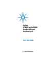
1
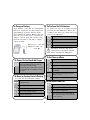
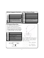
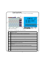
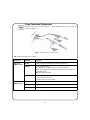
Agilent
U1602B and U1604B
Handheld Digital
Oscilloscopes
Quick Start Guide
Agilent Technologies
Safety Information
Use the product only as specified by the manufacturer.
Do not install substitute parts or perform any
unauthorized modification to the product. Return the
product to Agilent Technologies or a designated repair
center for service to ensure that safety features are
maintained.
Symbols
Earth Ground Terminal
Risk of electric shock
The Agilent U1600B Series handheld digital
oscilloscopes comply with the following standards.
CAUTION
(refer to safety information in manual)
• IEC 61010-1:2001 / EN61010-1:2001
• Canada: CSA C22.2 No. 61010-1:2004
• USA: UL 61010-1:2004
Equipotentiality
Safety Terms and Symbols
Direct and alternating current
WAR N IN G
Direct current
A WARNING notice denotes a hazard. It calls
attention to an operating procedure, practice, or the
like that, if not correctly performed or adhered to,
could result in personal injury or death. Do not
proceed beyond a WARNING notice until the
indicated conditions are fully understood and met.
Double insulation
Caution, hot surface
CAT III Measurement Category III
CA UT ION
A CAUTION notice denotes a hazard. It calls attention
to operating procedure, practice, or the like that, if not
correctly performed or adhered to, could result in
damage to the product or loss of important data. Do not
proceed beyond a CAUTION notice until the indicated
conditions are fully understood and met.
1
Safety Information
WA RN IN G
• Do not expose the circuit or operate the instrument
without its cover or while power is being supplied.
• Do not use exposed metal BNC or banana plug
connectors, use only the insulated voltage probes,
test leads and adapters that come with the
instrument.
• Do not supply any voltage when measuring
resistance or capacitance in meter mode.
• Do not operate the instrument if it does not operate
properly, have the instrument inspected by qualified
service personnel.
• Do not operate the instrument in wet or damp
environments.
• Do not operate the instrument in any environment
in a risk of explosion.
• Maintain a clean and dry condition to the
instrument’s surface.
Prevention of fire or injury:
• Use only the designated AC adapter and test leads
supplied with the instrument.
• Observe all ratings and markings of the instrument
before connecting to the instrument.
• When performing measurement, ensure that the
right safety and performance ratings of instrument
and accessories are used.
Maximum Input Voltages
•
•
•
•
•
•
Input CH1 and CH2 direct (1:1 Probe) — 300 V CAT III
Input CH1 and CH2 via 1:10 Probe — 600 V CAT III
Input CH1 and CH2 via 1:100 Probe — 600 V CAT III
Meter Input — 300 V CAT III, 600 V CAT II
Scope Input — 300 V CAT III
Voltage ratings are Vrms (50 Hz - 60 Hz) for AC sine
wave and VDC for DC applications.
CA UT ION
Maximum Floating Voltage
Prevention of electro-static discharge
• From any terminal to ground — 300 Vrms CAT III
(up to 400 Hz)
• Electro-static discharge (ESD) can result in damage
to the components in the instrument and
accessories.
• Select a static-free working location when installing
and removing sensitive components.
• Handle sensitive components to the minimum
extent possible. Do not allow contacts between
components and exposed connector pins.
• Transport and store in ESD preventive bag or
container that protects sensitive components from
static electricity.
• Connect the scope probe or test leads to
instrument before connecting to any active circuit
for testing. Before disconnecting the active circuit
from instrument, remove scope probe or test leads
from active circuit.
• Do not connect the ground wire to voltages higher
than 42 Vpeak (30 Vrms) from earth ground.
2
Table of Contents
Safety Information 1
Introduction 4
The Front Panel at a Glance
4
Getting Started
• To Inspect Package Contents 5
• To Charge a Battery 6
• To Power On the Handheld Scope 6
• To Reset to Factory Default Setting 6
• To Perform Self-Calibration 6
• To Set Time and Date 6
• To Set Auto Power Off 7
• To Select Language for Quick Help 7
• To Adjust Contrast of Display 7
• To Compensate Scope Probe 7
Scope Screen Display
8
Scope Connection Configuration 9
Meter Connection Configuration
Cursor Measurement
11
Save/Recall Setup and Waveform
Signal Triggering
12
Automatic Measurements 14
Data Logger 14
Quick Help
10
14
Performance Characteristics 15
3
12
Introduction
This quick start guide provides the basic information, front panel functions
and general specifications of Agilent U1600B Series handheld digital
oscilloscopes. The U1600B Series can also function as a digital multimeter
(DMM) and data logger. With its 4.5- inch LCD color display, it is capable of
clearly distinguishing waveforms from two channels. The U1600B Series
handheld digital oscilloscopes are high performance troubleshooting tools in
multi- industrial automation, process control, facility maintenance and
automotive- service industries. The U1600B Series comprises two models:
U1602B and U1604B, with 20 MHz and 40 MHz bandwidths, respectively. Both
models are dual- channel scopes with real- time sampling rate of up to 200
MSa/s. Users can use the Dual Waveform Math (DWM) and Fast Fourier
Transform (FFT) functions (in U1604B) to perform a quick waveform analysis
in both time and frequency domain. The U1600B Series with built- in 6000count resolution and true RMS comes with an auto range function that allows
users to perform quick and accurate DMM measurements. Additionally, with
data logger function, users can perform automatic data logging for all DMM
measurements.
The Front Panel at a Glance
Meter mode button
Softkeys to select submenu of
each function mode.
Scope mode button
Logger mode button
Auto measurement button
To access Cursor mode, press
and hold the button.
User mode button
Run/Stop button
To access Save/Recall mode,
press and hold the button
Trigger button
To access Trigger mode, press
and hold the button.
Autoscale button
For manual ranging setting, press
and hold the button.
Vertical scale button to
increase and reduce
volt/div for respective
channel.
Turn clockwise or anti-clockwise
for value selection and press the
knob to set the value.
Horizontal scale
button to
increase and
reduce time/
Power Switch button
Quick Help button
4
Getting Started
To Inspect Package Contents
Inspect and verify the following items for the standard purchase of
U1602B or U1604B, and any optional accessories you may have
Standard Item and
Accessories
Handheld digital
oscilloscope
2. Power cable
3. Ni- MH battery pack,
7.2 V
4. AC adapter
5. Two scope probes
(10:1) CAT III 600 V
6. DMM test lead
7. Hook Clip
8. Ground alligator clip
9. Medium jaw alligator
clip
10. USB cable
11. Quick Start Guide
4
3
2
1.
1
11
6
10
1.
2.
7
8
9
Optional Accessories
5
2
1
Soft casing
Scope probe (100:1)
CAT III 600 V with
ground alligator clip
5
To Charge a Battery
To Perform Self-Calibration
Upon delivery of the unit, the rechargeable
battery is required to be fully charged for
approximately 25 hours with the designated Agilent AC adapter. Ensure that you
have the correct line power cord. The AC
adapter converts input line voltages ranging from 100 VAC to 240 VAC to output
voltage 12 VDC.
To ensure the scope is operating properly,
perform the self- calibration. Before proceeding to the next step, ensure the scope
passes self- calibration.
Open User menu
Open Utility menu
Select MORE 3/4 page menu
Input: 100 V – 240 VAC
Output: 12 VDC, 2 A,
50/60 Hz
Self-calibration start
Disconnect all probe and meter
connections to the input terminal
before starting self- calibration.
To Set Time and Date
To Power On the Handheld Scope
User
To turn on or off the scope, press and hold the
power switch button for three seconds. A
basic self-test shall be executed
automatically upon power up. The scope will
be loaded with the last configuration setup of
the scope.
Open User menu
Open Utility menu
Select MORE 2/4 page menu
Select time format in MM/DD/YY or
YY/MM/DD
Select time set for Year, Month, Day, Hour,
Minute or Second
To Reset to Factory Default Setting
Turn rotary switch to set the time display
To recall the factor default settings:
Open Save/Recall menu by pressing and
holding the button
To Set Auto Power Off
User
Open Save/Recall Setup menu
Open User menu
Open Utility menu
Select MORE 1/4 page menu
Select MORE 1/4 page menu
Restore factory default settings
Select preference time (5 min/10 min/ 30
min/ 1 hr/ 2 hrs/ 4 hrs) or turn off the auto
power off function
Enter for “Restore OK?”
6
To Adjust Contrast of Display
To Select Language for Quick Help
Open User menu
Open User menu
Open Display menu
Open Utility menu
Select MORE 1/2 page menu
Select MORE 1/4 page menu
Enter once to release the fixed contrast value
Select language (English/French/Italian/
Portuguese/German/Spanish/Korean/
Japanese/Traditional Chinese/Simplified
Chinese)
Turn rotary switch clockwise to reduce
brightness (contrast value shows increment
from 20 to 79) and vice versa
Enter once to fix the contrast value
To Compensate Scope Probe
To compensate the probe characteristic to
the scope’s channel, perform probe
adjustment. This step must be performed
whenever a passive probe is first attached to
the input channel. Connect the passive probe
to channel 2 and probe contact to channel 1
to obtain input signal 3 Vp- p with 1 kHz.
Open User menu
Open Utility menu
Select MORE 3/4 page menu
Enter probe calibration
Ensure the shape of the displayed pulse is
properly compensated. If not, adjust the
trimmer capacitor to obtain the flattest
square wave possible.
Select probe attenuation
Enter to start probe adjustment
Proper compensated
Over compensated
Under compensated
Trimmer capacitor
7
Scope Screen Display
Agilent U1600B Series offers a 320×240 color LCD display.
Figure 1 Oscilloscope display
Figure 2 Multimeter display
Table 1 Descriptions of the handheld digital oscilloscope main display
No.
Description / Function
1
To display the status of channel 1 and channel 2 in volt/div and time/div
2
To display input waveform from channel 1 and channel 2
3
To display trigger position in window
4
To show the battery level and to indicate battery charging when connected to AC line power
5
To display signal acquisition status
6
To display signal triggering mode and the status of the triggering
7
To display resulting auto measurement values
8
To display time
9
To display menu of the functions by pressing the respective buttons and softkeys
10
To display numeric measurement value in meter mode
11
To indicate the meter is in auto ranging mode
12
To display analogue bar graph for measurement value
8
Scope Connection Configuration
Connect the scope in either single or dual channels with scope probes as
shown in figure 3.
Figure 3 Connection for scope measurement
Table 2 Function descriptions of scope menu
Scope Menu
Sub Menu
Description
CH1 / CH2
MORE 1/2 page
On/Off
To turn on or off waveform display for channel 1 and channel 2
Coupling
To select channel coupling:
DC: To display both AC and DC component of the input waveform
AC: DC offset voltage will be removed from the input waveform, only AC component will be shown
GND: Input signal is grounded
Position
To adjust the reference ground position, turn rotary switch clockwise to raise to
positive position and vice versa
To set the position, press rotary switch
Probe
Select the probe attenuation 1X, 10X or 100X
Invert
To turn on or off waveform invert function
Position to 0
Reset the reference ground position to zero volt
CH1 / CH2
MORE 2/2 page
9
Meter Connection Configuration
The U1600B Series offers high precision, rugged auto ranging in true RMS
with analog bar graph display. Enter Meter mode to select Volt Meter,
Ohm Meter or Auxiliary Meter. Refer to Figure 4 for meter measurement
connection.
N O TE
Auto ranging is set as the default mode
for all voltage and resistance measurements. To vary measurement range manually, press Autoscale button to enable
manual ranging and select the preference
range by pressing the same button. To
enable the auto range function, press and
hold the same button until beeper emitted.
Figure 4 Connection for meter measurement
Table 3 Measurement functions of each meter
Meter Menu
Sub Menu
Volt Meter
Ohm Meter
Relative
Min, Max, Average
Restart Test
DC
√
√
√
AC+DC
√
√
√
AC
√
√
√
Resistance
√
√
√
√
√
Diode Test
Continuity
Aux Meter
Capacitance
√
Temperature Meter (oC/oF)
√
√
√
Ampere Meter (AC/DC)
√
√
√
Humidity Meter (%RH)
√
√
√
Pressure Meter (psi/kPa)
√
√
√
10
Cursor Measurement
Use cursor function to obtain a precise and accurate measurement in
voltage and time at any desired point of a waveform. To enter cursor
mode, press and hold the Measure button. To navigate cursor in a waveform, use rotary switch to move the horizontal or vertical cursor and
press rotary switch to set the cursor position.
Cursor measurement display
• The delta (symbol) indicates the
difference between X1 and X2 or
between Y1 and Y2 cursors
• For X cursor, the X cursors display
the values (volts or amperes) and
time relative to the cursors trigger
point for the selected waveform
source
• For Y cursor, the Y cursors display
the values (volts or amperes) for
the selected waveform source
Figure 5 Y cursor measurement
Table 4
Function descriptions of cursor menu
Cursor Menu
Sub Menu
Description
Cursor
Function
To turn off or select cursor measurement type:
X cursor: To measure any point at time base (cursor is parallel to the vertical
axis)
Y cursor: To measure any point at voltage level (cursor is parallel to the horizontal axis)
Mode
To select X1, X2 or X1+X2 cursor for X cursor function
To select Y1, Y2 or Y1+Y2 cursor for Y cursor function
Source
To select channel 1, channel 2 or Math for cursor measurement
11
Save/Recall Setup and Waveform
To enter Save/Recall mode, press and hold the Run/Stop button. This
function allows you to save up to 10 waveforms and configuration settings
into the unit’s internal memory or an external USB flash memory device
(optional).
Table 5
Function descriptions of save and recall menu with and without USB flash memory connected
Scenario
Sub Menu
Description
USB flash
memory
not
connected
Save/Load Setup
Save or recall configuration setting
Save/Load Waveform
Save or recall waveform
Erase Setup
Delete stored configuration setting
Erase Waveform
Delete stored waveform
Save
Save waveform or configuration setting
Recall
Download waveform or configuration setting from USB memory device
Erase
Delete saved file
Clear Waveform
Delete the recalled waveform and configuration setting display on screen
USB flash
memory
connected
Signal Triggering
This signal triggering function aims to obtain a stable and representative
signal display from an unstable signal. This function triggers the scope
when to start acquiring data and display a waveform based on the
selected trigger type. To enter trigger menu, press Trigger button.
Table 6
Function descriptions of trigger menu
Trigger Menu
Edge Trigger
Sub Menu
Description
More 1/2
page
Source
To select channel source 1 or 2 for triggering
Slope
To select rising and falling slope
More 2/2
page
Coupling
To select input coupling to DC, AC, HF-Rej (High Frequency Reject),
LF-Rej (Low Frequency Reject) or Noise-Rej (Noise Reject)
Level
To set trigger level for Manual, TTL, ECL or Set to 50%.
For manual adjustment, change the rigger level by turning rotary
switch
12
Trigger Menu
Pattern
Trigger
Sub Menu
More 1/3
page
More 2/3
page
More 3/3
page
Pulse Trigger
More 1/2
page
More 2/2
page
Video Trigger
More 1/2
page
More 2/2
page
Description
Input 1 Logic
To select input logic 1 as CH1 High or Low and CH2 High or Low
Input 1 Level
To set trigger level for Manual, TTL, ECL or Set to 50%.
For manual adjustment, change the rigger level by turning rotary
switch
Input 2 Logic
To select input logic 2 as CH1 High or Low and CH2 High or Low
Input 2 Level
To set trigger level for Manual, TTL, ECL or Set to 50%.
For manual adjustment, change the trigger level by turning rotary
switch
Gate
To set logic gate AND, OR, NAND or NOR
Condition
To select trigger condition to Shorter, Longer, Between or NonBetween of a set value. To set the trigger value, turn and press the
rotary switch
Source
To select channel source 1 or 2 for triggering
Level
To set trigger level for Manual, TTL, ECL or Set to 50%.
For manual adjustment, change the trigger level by turning rotary
switch
Polarity
To set positive or negative polarity
Condition
To select trigger condition to Shorter, Longer, Between or NonBetween of a set value. To set the trigger value, turn and press the
rotary switch
Standard
To select video signal type: 625/PAL, SECAM or 525/NTSC
Source
To select channel source 1 or 2 for triggering
Even/Odd
To select trigger for odd or even field of the video signal
Line
To set the number of lines for the signal display
13
Automatic Measurements
The following automatic measurements can be accessed by pressing the
Measure button. Up to four measurement menus with 22 measurement
options can be selected by turning rotary switch. You can activate the individual softkey and press the rotary switch to set the measurement type.
Table 7
List of automatic measurement options
Time
Measurements
Voltage
Measurements
Phase and Delay
Preshoot and
Overshoot
•
•
•
•
•
•
•
•
•
•
•
•
•
•
•
•
•
• Phase
• Delay
• Preshoot
• +Overshoot
• –Overshoot
+Duty
–Duty
Frequency
Period
Rise Time
Fall Time
+Width
–Width
Mean
Cycle Mean
Amplitude
Base
Maximum
Minimum
Peak- to- Peak
RMS
Top
Data Logger
The data logger acts as a recorder to log and plot input signal trend. This
function is applicable to voltmeter, ohmmeter and auxiliary meter
measurements. Refer to Table 3 for measurement functions of each meter.
Quick Help
The U1600B Series includes built- in Quick Help support. To view the
quick help for each function or subfunction, press the Help button. You
can turn the rotary switch clockwise to go to the next page. Press the
Help button again to exit the Quick Help. The instrument provides Quick
Help in English, optionally you can download your preference language
from the product webpage: www.agilent.com/find/handheldscope. To view
the installed Quick Help language, enter Utility mode in the User menu
and press F2 on page 1/4 for language selection.
For more detailed information, please refer to the Agilent U1602B and U1604B User’s and
Service Guide on Agilent Web site.
14
Performance Characteristics
Performance Characteristic
U1602B
U1604B
Bandwidth
20 MHz
40 MHz
Maximum Real Time Sample
Rate
200 MSa/s
Channels
Maximum recording length
2
125,000 points, viewable on screen with zoom function
Display
4.5” color LCD
Vertical resolution
8 bits
Vertical sensitivity
5 mV/div to 100 V/div (1:1 scope probe)
50 mV/div to 1 kV/div (10:1 scope probe)
500 mV/div to 10 kV/div (100:1 scope probe)
Vertical zoom
Time base range
Vertical expand
50 ns/div to 50 s/div
Input coupling
True RMS Multimeter
FFT
Dual Waveform Math
10 ns/div to 50 s/div
DC,AC, Ground
6000 resolution counts for multimeter functions:
• Volt Meter: VDC, VAC and VDC+VAC measurement
• Ohm meter: Resistance, Diode Test, Continuity and Capacitance measurement
• Auxiliary meter: Temperature and Ampere measurement
Not Available
Rectangular, Hanning, Hamming, BlackHarris
CH1+CH2, CH1-CH2, CH2-CH1
Acquisition modes
Normal, Average, Peak
Trigger modes
Edge, Pulse, Pattern, Video
Cursor modes
Voltage (Y cursor), Time (X cursor)
Sweep modes
Auto, Normal, Single Shot
Automatic measurements
Voltage measurement: Peak-to-peak, Maximum, Minimum, Amplitude, Top, Base, Mean,
Cycle mean, RMS (DC), Preshoot, +Overshoot, –Overshoot
Time measurement: Frequency, Period, +Width, –Width, Rise Time, Fall Time, Phase,
Delay
15
Performance Characteristics
Data Logger
Auto range time span from 150 seconds to 20 days full screen display.
Data logging for voltage, ohm and auxiliary measurement in maximum, minimum and average
data points.
I/O Interface to PC
USB 2.0 full speed
General Characteristics
Physical size
13.8 cm width × 24.1 cm height × 6.6 cm depth
Weight
Warranty
Battery Type
Electrical Safety
1.5 kg
3 years for main unit
3 months for standard shipped accessories unless otherwise stated
Agilent U1571A, Ni-MH battery pack, 7.2 V
IEC 61010-1:2001/ EN61010-1:2001
Canada: CSA C22.2 No. 61010-1:2004
USA: UL 61010-1:2004
Environment Characteristics
0 oC to 50 oC
Operating temperature
–20 oC to 70 oC
Storage temperature
Operating altitude
2000 meter
16
www.agilent.com
Contact us
To obtain service, warranty or technical
support assistance, contact us at the following phone numbers:
United States:
(tel) 800 829 4444
(fax) 800 829 4433
Canada:
(tel) 877 894 4414
(fax) 800 746 4866
China:
(tel) 800 810 0189
(fax) 800 820 2816
Europe:
(tel) 31 20 547 2111
Japan:
(tel) (81) 426 56 7832 (fax) (81) 426 56
7840
Korea:
(tel) (080) 769 0800
(fax) (080) 769 0900
Latin America:
(tel) (305) 269 7500
Taiwan:
(tel) 0800 047 866
(fax) 0800 286 331
Other Asia Pacific Countries:
(tel) (65) 6375 8100
(fax) (65) 6755 0042
Or visit Agilent worldwide web at:
www.agilent.com/find/assist
Product specifications and descriptions in
this document subject to change without
notice.
© Agilent Technologies, Inc. 2006-2008
Printed in Malaysia
First Edition, December 1, 2009
U1602-90015
Agilent Technologies