1
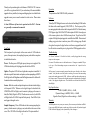
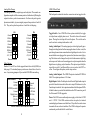
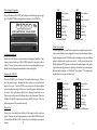
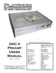
MORE WAYS TO ACHIEVE
INCREDIBLE SOUND... FROM MSB
The Nelson Upgrade (Factory Installed Only)
A major audiophile upgrade to the LINK III, adding a professional balanced digital input, all
new analog output stage and beefed up power supplies. Must hear to believe!
$485
Upsampling (User Installable)
MSB has created a way to upsample from ANY lower audio standard to 24 bit - 96 kHz.
Includes extra jitter reduction and back panel switch.
$199
HDCD (User Installable)
Making the Link III HDCD compatible allows you to take full advantage of the benefits of
the HDCD format. Auto detection and front panel indicator. (Simultaneously works with
the Upsampling Upgrade)
$199
192 kHz (User Installable)
In keeping with MSB’s goal of providing clients with the most up-to-date technology, the
Link III circuits are fully upgradable. As 192 kHz software and hardware becomes
available, we plan to offer an upgrade.
Virtual 3D (User Installable)
This upgrade allows those with two speaker setups to enjoy Pro Logic through a series of
digital filters that project five “virtual speakers” into space.
$149
MSB GOLD LINK DAC
The GOLD LINK DAC provides an unparalleled sound experience with virtually any
available digital source. Four internal stereo DA converters give improved signal-to-noise
and channel separation characteristics, providing outstanding signal quality to your
preamplifier. The Gold has little output filtering for the best possible sound, electromagnetic
shielding of all the key components and high performance, high slew rate operational
amplifiers. This DAC delivers incredible “focus” and depth of soundstage to the listening
environment.
(Full value LINK trade-in offered!) $1295
MSB Platinum Link DAC
This 46 bit - 384 kHz sign magnitude R2R ladder DAC with four independent discrete
converters goes way beyond any other DAC. It can handle greater resolution and higher
sampling frequencies than any existing format, for maximum S/N and channel isolation. The
Platinum upsamples lower sampling rate sources to 24 bit - 96 kHz. It has up to 5 digital
inputs (ATT glass, Toslink optical, Coaxial SP/DIF, Balanced AES/EBU and IEEE 1394
Firewire) as well as balanced and single-ended analog outputs. Selectable digital filter response (interpolation and slope) give you complete control. The painstaking detail, care and
phenomenal sound you demand from a high-end DAC.
(Full value LINK or Gold LINK trade-in offered!) $3395
MSB Interconnects
HIGH QUALITY, AFFORDABLE CABLE PRODUCTS
6 RCA to DB-25
Digital Audio
AC3-RF - for LD
Audio - Triple Shielded
S-Video - 2m
Video
Toslink Optical 1m - also 2m, 15m
Red Hawk Optical 1m - also 3m, 20m
MSB Custom Digital
$95
$35
$35
$45
$35
$35
$45
$95
call
Users Manual
Thank you for purchasing the world famous LINK DAC III. I am sure
you will be very pleased with it. If you ordered any of the user installable
upgrades factory installed, a storage and shipping box is included for the
upgrade in case you ever need to return it to us for service. Please retain
these boxes.
At least 100 hours of burn-in is required on this DAC. Customers generally recommend one month.
Front Panel
Operation
The operation of the LINK III is fully automatic.
Software
Virtually all PCM digital sources can be decoded including 24/96K and in
the future with a small upgrade, 192K (DVD-A). The frequency of the
incoming signal is indicated on the front panel with LEDs. Note that many
DVD players play 96K-24 bit DVDs but output at 48 kHz. Some players
offer a menu option to select 96K but many do not. To get the true 96K
output a 96K digital output upgrade is available from MSB. Discussion of
adding copy protection is underway in an AES working group. Should
decryption be required to play back new software, an upgrade board will
be offered at a reasonable price to plug into the LINKs upgrade sockets.
The front panel is quite simple with no user controls. LEDs indicate
power, the input source, the sampling frequency and whether an option
is installed and is active.
Troubleshooting
Power - The blue power LED lights up any time power is applied. The
LINK should always be left plugged in with the blue LED lit.
No sound - Check that source is valid audio source. Change to a standard CD just
to be sure. Check that analog outputs are connected to the “outputs” not the
“inputs”.
Option - The option LED will never light unless an option is installed. It
indicates a specific function for each option, such as upsampling or HDCD.
It will light in the full brightness and half brightness mode for further differentiation between multiple options.
Still no sound - connect an analog output from the source directly to the volume
control. Verify that the rest of the system is working. Now move the same analog
output to the analog input on the LINK. Add a new cable from the analog output to
the volume control. Disconnect the digital inputs and confirm that the system still
works. Now plug in a digital source. You should hear a click and the front LEDs
should light.
Source - Both the coaxial and optical inputs are indicated on the display
with separate LEDs. When an active digital signal is attached to the
LINK III the LED will light, even if no music is playing, or the source is
data (like Dolby Digital or DTS). If both sources are active, both LEDs
will light, but the COAXIAL input will take priority. If no LED is lit, the
analog pass-through is active.
Sample Frequency - These LEDs indicate the incoming sampling frequency, whether music is playing or not, and whether the source is data
or not. The 192 LED will not light without the 192 option installed.
2
No “Source” indicated - Check for bad cable, or cable plugged into the wrong
output on the transport.
Key Specifications
THD+N (0dBFS, 1kHz) = -96dB,
Dynamic Range (-60dBFS, 1kHz) = -106dB
Signal to Noise (Digital zero with no muting) = -106dB
Warranty
All MSB products carry a one year warranty. No returns accepted without an RMA.
Upon receipt, MSB will repair or replace any defective product. All product shipped
FOB La Honda. Shipping is the responsibility of the consignee.
7
Analog Filter Change
The analog filters in the output stage can be adjusted. The normal configuration complies with the common practice of rather heavily filtering the
outputs to achieve perfect measurements. For those who prefer greater
dynamics and attack, try removing the jumpers from positions 2 and 5 of
J16. They can be placed on positions 1 and 4 for safe keeping.
J16
Ground
L Filter 1
L Filter 2
Ground
R Filter 1
R Filter 2
Ground
+8V, -8V
1234567890
1234567890
1234567890
1234567890
1234567890
1234567890
1234567890
1234567890
1234567890
1234567890
1234567890
J16
1
2
3
4
5
6
7
8
Ground
L Filter 1
L Filter 2
Ground
R Filter 1
R Filter 2
Ground
+8V, -8V
123456789
123456789
123456789
1234567890
1234567890
1234567890
123456789
123456789
123456789
1234567890
1234567890
1
2
3
4
5
6
7
8
NORMAL FILTERS
REDUCED FILTERING
Other Options
Headers J18 and J19 are for the upgrade boards also sold by MSB (see
back page). The standard jumper positions are shown below for reference. Any missing jumpers will prevent the LINK III from working.
DSP Headers
Ground
S/PDIF
S/PDIF (inverted)
Ground
Digital Active
Option 1
192 kHz
Ground
J18
J19
123456789
123456789
123456789
123456789
123456789
123456789
123456789
123456789
123456789
123456789
123456789
1
2
3
4
5
6
7
8
1234567890
1234567890
1234567890
1234567890
1234567890
1234567890
1234567890
1234567890
1234567890
1234567890
1234567890
Ground
Data
Bit Clock
L/R Clock
M Clock
Data Flag
Ground
NORMAL POSITION OF LINK III JUMPERS
6
LINK III Back Panel
The back panel contains the interface connectors and one toggle switch.
Toggle Switch - On a LINK III with no options installed, the toggle
switch performs a digital phase invert. The switch down is the normal
phase. Placing the switch up will invert the phase. This switch can be
used to activate certain option boards as well.
Analog Audio Input - The analog input provides a high quality passthrough switching feature that has many applications. In other words, the
pass-through connections are made unless a digital input is active. Active
means that the source plugged in is powered on, but not necessarily playing. This feature can be changed to only switch when nonzero digital signals are present. In this case the analog input is only interrupted when the
digital source is playing, not just turned on. This option is specifically designed for use with C and Ku satellite receivers such as the 4DTV receiver. To configure this option, see the setup section.
Analog Audio Outputs - The LINK III outputs a standard 2V RMS at
0 dB. The output impedance is 330 ohms.
Digital Inputs - Both a Toslink optical and Coaxial Digital audio input is
provided. Autodetection selects either active input. If both are active, the
Coaxial input is selected. Active inputs are indicated with front panel LEDs.
A blank location is provided for installation of an XLR connector, part of
the Nelson and 192 kHz upgrades.
Power- The LINK uses an outboard power supply, with at least +8VDC
and +/- 15VDC. The LINK contains no fuses to replace, but instead
contains high-performance resettable fuses. They allow the unit to return
to normal after an overload condition. The LINK is designed to operate
continuously, and should be left on at all times.
3
J14
Power Supply Upgrades
The performance of the LINK can be improved with a larger power supply. The MSB P1000 is designed as an add-on to the LINK III.
123456789
123456789
123456789
123456789
123456789
123456789
$299
J14
123456789
123456789
123456789
Zero Option
Data
Data (inverted)
1234567890
1234567890
1234567890
L/R Clock
Reset
Ground
Data Flag
L/R Clock
Reset
Ground
Data Flag
NORMAL PHASE
Configuration Options
Inside the LINK III are several headers with jumpers installed. They
change various functions of the LINK III and allow upgrades to be installed. Several options can be set by the user including phase invert,
digital zero switching and a modification to the analog filter.
Opening the LINK III
Place the LINK III on a soft surface like a tablecloth or carpet. Disconnect the power supply. Remove the three philips screws on the back
edge of the cover. Turn the LINK over and remove the three philips
screws from the front edge of the cover. Carefully separate the base from
the cover. Pick up the base and flip it over, placing it inside the cover.
Take care not to disconnect the ribbon cable to the front panel. Place the
LINK so that the RCA connectors are facing AWAY from you. This way
all the diagrams will be oriented correctly.
Phase Invert
Phase invert is normally switchable with the toggle switch on the rear
panel. Phase invert can be permanently set inside the LINK III instead.
Locate the header labeled J14. Remove the switch and place a jumper as
shown.
4
Zero Option
Data
Data (inverted)
INVERTED PHASE
Digital Zero Option
The analog bypass is normally interrupted when a digital input is active.
Active means that the source plugged in is turned on, not necessarily playing, but just powered on. This feature can be changed to only switch when
nonzero digital audio signals are present. It will ignore data such as
Dolby Digital and DTS signals. In this case the analog input is only interrupted when the digital source is playing valid audio, not just turned on.
Remove the first jumper on J 14 labeled “Zero Option”. The jumper may
be placed on just one pin for future use.
J14
J14
1234567890
1234567890
1234567890
123456789
123456789
123456789
Zero Option
Data
Data (inverted)
1234567890
1234567890
1234567890
1234567890
1234567890
Zero Option
Data
Data (inverted)
L/R Clock
Reset
Ground
Data Flag
L/R Clock
Reset
Ground
Data Flag
NORMAL SWITCHING
ZERO OPTION SWITCHING
5