1
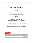
SSP-599-F-ISSUE4.0
SERVICE MANUAL
FOR
MODEL SSP-599-F
SPEAKERPHONE / HANDSET
COMBINATION TELEPHONE
Serving the Telephone Industry Since 1930
Communication Equipment
& Engineering Company
519 W South Park Street
Okeechobee, FL 34972
Voice: 863-357-0798
Fax:
863-357-0006
Issue 4.0
IMPORTANT INFORMATION
FOR
CUSTOMER
Please fill in before you continue.
The following information is necessary when calling CEECO for assistance.
MODEL NUMBER
MODEL SSP-599-F
SERIAL NUMBER
DATE MANUFACTURED
LOCATION INSTALLED
For us to better serve you, please have this information available when calling for
technical support.
CEECO
Communication Equipment & Engineering Company
519 W South Park Street
Okeechobee, FL 34972
863-357-0798- telephone
863-357-0006- facsimile
[email protected]
www.ceeco.net
CEECO
Communication Equipment & Engineering Company
PROPRIETARY
2
Issue 4.0
TABLE OF CONTENTS
SECTION
PAGE
1.0 INTRODUCTION..................................................................................................... 4
2.0 GENERAL................................................................................................................. 5
3.0 OPERATION ............................................................................................................ 5
4.0 RECOMMENDED TOOLS .................................................................................... 6
5.0 INSTALLATION NOTES AND ASSEMBLY INSTRUCTIONS ....................... 6
6.0 TESTING................................................................................................................... 7
7.0 SPECIFICATIONS................................................................................................... 8
8.0 PARTS LIST ............................................................................................................. 9
9.0 FCC NOTICE........................................................................................................... 10
10.0 REPAIR AND RETURN INFORMATION........................................................ 11
11.0 WARRANTY POLICY ......................................................................................... 12
CEECO
Communication Equipment & Engineering Company
PROPRIETARY
3
Issue 4.0
1.0
INTRODUCTION
This manual provides installation, operation and specification information for the
CEECO Model SSP-599-F Stainless Steel Panel Telephone.
The information in this manual is subject to change without notification.
For information not included in this manual, please call or write:
CEECO
Customer Service
519 W South Park Street
Okeechobee, FL 34972
863-357-0798- telephone
863-357-0006- facsimile
[email protected]
www.ceeco.net
2.0
3.0
GENERAL
2.1
The CEECO Model SSP-599-F Handsfree/Handset telephone is a sturdy,
vandal resistant, stainless steel panel speakerphone, equipped with a
handset and keypad.
2.2
The phone is designed for placing normal phone calls with either the
speakerphone or the handset, and allows the user to switch modes during
the phone call.
2.3
The SSP-599-F is equipped with an audible ringer and can receive
incoming calls.
2.4
The telephone is also equipped with a red LED light to indicate when the
telephone is off-hook.
OPERATION
3.1
A phone call may be initiated from either the handset or the speakerphone.
To place a call, lift the handset or press the speakerphone button and dial
the intended number on the keypad. When the called party answers, a
normal telephone conversation is allowed.
CEECO
Communication Equipment & Engineering Company
PROPRIETARY
4
Issue 4.0
3.2
To change from handset operation to speakerphone, press the
speakerphone push button and then hang up the handset. A normal
speakerphone conversation is then allowed.
3.3
To change from speakerphone to handset operation, pick up the handset
and then press the speakerphone button. Normal handset operation should
follow.
3.4
The phone need not be switched at all. The call may be made entirely
with the handset or entirely with the speakerphone.
3.5
If a call is placed to the phone, it may be answered in either mode and
switching between modes would be as stated above.
NOTE: When switching between the two modes (speakerphone and
handset) be sure to activate one device before deactivating the
other to avoid an accidental hang up.
3.5
4.0
To end the phone call in handset mode, simply hang up the handset. To
end the phone call in speakerphone mode, press the speakerphone button.
When the telephone has actually been hung up, the red light will turn off.
RECOMMENDED TOOLS
Security Tool (CEECO P/N 301-064) sold separately.
Screw Drivers – Flat Blade and Phillips Head.
Wire Cutters/Strippers.
Mounting hardware and appropriate tools for installing mounting box.
5.0
INSTALLATION NOTES AND ASSEMBLY INSTRUCTIONS
5.1
Using a 301-064 security tool (sold separately) remove the six (6) security
screws.
5.2
Remove the telephone assembly from its mounting box and place it
carefully out of harms way.
NOTE: Avoid contacting the internal parts of the telephone assembly
with other objects, as this may cause damage to the telephone.
Install the mounting box in the desired location (vertical surface).
5.3
Run the inside station wire through the mounting box and terminate the
wire on the RJ11C terminal block.
5.4
The use of gas tube or carbon station protectors is recommended. The
station ground should not exceed 50 ohms.
CEECO
Communication Equipment & Engineering Company
PROPRIETARY
5
Issue 4.0
5.5
Plug the modular line cord from the PC board into the RJ11C terminal
block.
5.6
Dress the line cord away from the mounting holes and seat the phone into
the mounting box.
5.7
Secure the telephone assembly by replacing and tightening the six (6)
security screws.
*****WARNING*****
6.0
A.
Never install telephone wiring during a lightning storm.
B.
Never install telephone jacks in wet locations unless the jack is
specifically designed for wet locations.
C.
Never touch uninsulated telephone wires or terminals unless the
telephone line has been disconnected at the network interface.
D.
Use caution when installing or modifying telephone lines.
TESTING
6.1
Lift the handset and place a call to another location using the keypad. A
normal telephone conversation should be allowed. The red LED light
should illuminate steadily.
6.2
Press the speakerphone button and hang up the handset. Verify that a
normal speakerphone conversation is allowed.
6.3
Lift the handset and press the speakerphone button. Normal telephone
operation should return to the handset.
6.4
End the call by hanging up the handset. The red LED light should go out.
6.5
Press the speakerphone button and place a call to another location using
the keypad. Switch from speakerphone operation to handset operation and
back again as above.
6.6
End the call by pressing the speakerphone button to hang up the phone.
The red LED light should go out.
6.7
Place a call to the telephone using another telephone or a test set.
CEECO
Communication Equipment & Engineering Company
PROPRIETARY
6
Issue 4.0
7.0
6.8
Verify that the ringer is working and answer the phone by either lifting the
handset or pressing the speakerphone button. The red LED light should
illuminate steadily. Verify that a normal conversation is allowed. Switch
between the two modes and verify that they function well. End the call by
hanging up the phone as appropriate for last mode being used.
6.9
The telephone is now ready for operation.
SPECIFICATIONS
Input Power:
C.O. Line Powered (48-52 Volt Loop)
Loop Current Handset:
25 mA min. 80 mA max.
Loop Current Speakerphone: 23 mA min 80 mA max.
Impedance:
600 Ohms.
Output Handset:
-9.0 to –11.0 dbm.
Output Speakerphone:
-4.0 to –6.0 dbm
Environmental:
Temperature 0°C to 50°.
Humidity
20% to 90% non-condensating.
Dimensions:
(SSP)
10.25 High x 13.125Wide x 5.50Deep
(handset on hook).
Mounting:
Mounting Box/Vertical surface mount.
(Mounting Box Dims)– 8.54H x 11.52L x 2.65
Weight:
Approximately 6lb. - Telephone Assembly
D
CEECO
Communication Equipment & Engineering Company
PROPRIETARY
7
Issue 4.0
Approximately 3.5lb - Mounting Box
Approximately 9.5lb.- Total
8.0
UL listed no.:
60F5
FCC registration:
BW8USA-73021-MT-E
Ringer equivalence:
0.4a
Type jack:
RJ11C
PARTS LIST
QUANTITY PART NUMBER
DESCRIPTION
1
301-018
Modular line cord.
1
301-054-UL
Modular Connector (RJ11C).
1
660-100
CEECO SPK PC board.
1
6020
Momentary Panel Switch.
1
14024
Speaker.
1
14067
Microphone.
1
301-004
Handset with Armored Cord
1
735-100
Model 730 Metal Button Tone Dial
1
301-581
Tongue and Bracket Assembly
CEECO
Communication Equipment & Engineering Company
PROPRIETARY
8
Issue 4.0
1
301-588
Hookswitch Cradle
2
301-570
Microswitch Assembly
1
401-009
Ringer
1
301-009
Network
1
6023
LED
1
308-016
Handset Swivel
1
301-052
Grommet
1
13074-C
PC Board
301-064
Security Tool.
OPTIONS
1
CEECO
Communication Equipment & Engineering Company
PROPRIETARY
9
Issue 4.0
9.0
FCC NOTICE
9.1
FCC REGISTRATION AND REPAIR INFORMATION
Your new telephone has been registered with the Federal Communication
Commission (FCC) in accordance with Part 68 of its rules. The FCC
requires that you be advised of certain requirements involving the use of
this telephone.
9.2
CONNECTION WITH THE NATIONWIDE TELEPHONE NETWORK
The FCC requires that you connect this telephone to the Nationwide
Telephone Network through a registered jack provided by the Telephone
Company in your area. This jack is a modular outlet, which you can order
from your local telephone company.
9.3
NOTIFICATION TO THE TELEPHONE COMPANY
Before connecting this telephone, the FCC requires that you notify your
local telephone company business office. The number is in the front of
your phone book.
Tell them:
The "line" to which you will connect the telephone (that is, your phone
number) and the telephone's FCC registration number and ringer
equivalence number. These numbers are listed in section 9.0.
The FCC further requires that you notify your local telephone company
when permanently disconnecting this telephone.
CEECO
Communication Equipment & Engineering Company
PROPRIETARY
10
Issue 4.0
10.0 REPAIR AND RETURN INFORMATION
10.1
WARRANTY REPAIR
Any device returned requiring warranty service, repair or credit must be
accompanied with a "Return Material Authorization" (RMA) FORM. It
must include return shipping instructions, original purchase order number
and special marking instruction. A description of the trouble observed
must be attached to the defective unit. This information must be inside the
shipping container.
10.2
DIRECT ALL INQUIRES TO:
CEECO
Repair Department
863-357-0798- telephone
863-357-0006- facsimile
[email protected]
www.ceeco.net
10.3
NON-WARRANTY REPAIR
CEECO will repair equipment out of warranty for a set charge plus parts.
The customer must pay the shipping costs both directions.
10.4
RETURN FOR CREDIT
Material may be returned for credit only with prior approval. Material
authorized for return is subject to a 20% restocking charge based on the
manufacturer’s list price. Return RMA must be requested no later than 30
days after original shipment.
CEECO
Communication Equipment & Engineering Company
PROPRIETARY
11
Issue 4.0
11.0 WARRANTY POLICY
11.1
GENERAL
CEECO products are guaranteed to be free of defects in material and
workmanship for a period of 12 months from the date of original
shipment, if properly installed and maintained. This warranty is limited to
the value of material only.
CEECO will repair or replace any unit during this period if found to be
defective for reasons other than abuse and improper use or improper
installation. It is the buyer’s responsibility to return the defective unit to
the factory. CEECO will then repair or replace any defective parts and
return them to the buyer free of charge.
11.2
PRINTED CIRCUIT BOARDS
Printed circuit boards should not be repaired in the field. If a unit is found
to be faulty, replace it with another unit and return the faulty unit to
CEECO for repair. Modifications by any one other than CEECO will void
the warranty.
CEECO
Communication Equipment & Engineering Company
PROPRIETARY
12