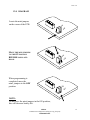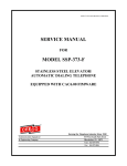
1
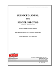
WPP-531-D2 OR SSP-511-D2-SPK1.07UNVL-ADA-ISSUE4.0
SERVICE MANUAL
FOR
MODEL WPP-531-D2
WEATHERPROOF TELEPHONE
OR
MODEL SSP-511-D2
STAINLESS STEEL PANEL TELEPHONE
WITH OPTIONAL SECOND-NUMBER AUTO DIAL
FEATURE AND OPTIONAL ADA FEATURE
EQUIPPED WITH SPK1.07UNVL FIRMWARE
Serving the Telephone Industry Since 1930
Communication Equipment
& Engineering Company
519 W South Park Street
Okeechobee, FL 34972
Voice: 863-357-0798
Fax:
863-357-0006
Issue 4.0
IMPORTANT INFORMATION
FOR
CUSTOMER
Please fill in before you continue.
The following information is necessary when calling CEECO for assistance.
MODEL NUMBER
MODEL WPP-531-D2 OR SSP-511-D2
WITH SPK1.07UNVL FIRMWARE
SERIAL NUMBER
DATE MANUFACTURED
LOCATION INSTALLED
For us to better serve you, please have this information available when calling for
technical support.
CEECO
Communication Equipment & Engineering Company
519 W South Park Street
Okeechobee, FL 34972
863-357-0798- telephone
863-357-0006- facsimile
[email protected]
www.ceeco.net
CEECO
Communication Equipment & Engineering Company
PROPRIETARY
2
Issue 4.0
TABLE OF CONTENTS
SECTION
PAGE
1.0 INTRODUCTION..................................................................................................... 4
2.0 GENERAL................................................................................................................. 4
3.0 PROGRAMMING .................................................................................................... 5
PROGRAMMING CONTINUED…....................................................................... 6
PROGRAMMING CONTINUED…....................................................................... 7
4.0 TESTING/OPERATION ......................................................................................... 8
5.0 RECOMMENDED TOOLS AND TEST EQUIPMENT ...................................... 9
6.0 INSTALLATION NOTES AND ASSEMBLY INSTRUCTIONS ....................... 9
7.0 SPECIFICATIONS................................................................................................. 10
8.0 PARTS LIST ........................................................................................................... 11
9.0 FCC NOTICE.......................................................................................................... 12
10.0 REPAIR AND RETURN INFORMATION......................................................... 13
11.0 WARRANTY POLICY .......................................................................................... 14
12.0 DIAGRAM............................................................................................................... 15
CEECO
Communication Equipment & Engineering Company
PROPRIETARY
3
Issue 4.0
1.0
INTRODUCTION
The practices in this manual provide installation and maintenance information for
Model WPP-531-D2 or Model SSP-511-D2 Telephone, with optional secondnumber auto-dial feature and optional ADA feature, equipped with
SPK1.07UNVL firmware.
The information in this manual is subject to change without notification.
For information not included in this manual, please call or write:
CEECO
Customer Service
519 W South Park Street
Okeechobee, FL 34972
863-357-0798- telephone
863-357-0006- facsimile
[email protected]
www.ceeco.net
2.0
GENERAL
2.1
The CEECO hands free telephone is a sturdy, vandal resistant, stainless
steel speakerphone. Instead of a hookswitch and handset, the telephone
has a press to start/press to stop CALL button for the initiation and
termination of phone calls. Manual volume control is also provided inside
the telephone on the PC board.
2.2
The telephone provides an optional second-number auto-dial feature. This
allows a second number to be automatically dialed, when no answer is
received on the first auto-dial number. The phone can be programmed to
select the number of unanswered rings (1-9), after which it will
automatically release the second auto-dial number.
2.3
The telephone also has an optional ADA feature. This feature causes the
LED to illuminate RED during off-hook and dialing conditions and turn
GREEN after answer.
2.4
The microphone is muted during periods of dial tone to deter the use of
hand-held dialers to make fraudulent calls.
2.5
Incoming calls may be allowed or blocked and an automatic call
disconnect may be selected (1-9 minutes) depending on the programming.
2.6
Programming is accomplished by way of a DTMF keypad, which is
attached to the back of the telephone panel or provided separately.
CEECO
Communication Equipment & Engineering Company
PROPRIETARY
4
Issue 4.0
3.0
PROGRAMMING
NOTE: It is recommended that you ground yourself to prevent ESD
damage to the PCB(s).
3.1
Connect the telephone to a working telephone line or a DTMF test set.
3.2
Locate the pair of plastic mini-jumpers along the edge of the PC board.
Move them to the “ON” or inner most position as depicted in the diagram,
on the last page of this manual.
3.3
If the phone does not have a DTMF keypad mounted on the back of the
telephone panel, but rather one has been provided separately, connect the
keypad at this time. In order to connect a separate keypad, locate the
multicolor ribbon cable extending from the printed circuit board with a
white connector on the loose end. Connect that white connector to the
white connector on the keypad. The connectors will only mate one way.
3.4
Press the “CALL” button and wait for dial tone before entering
programming digits.
3.5
Utilizing the keypad, enter # 9 7 # 1 8 # # 1 9 # # 0 1 #, which will clear
all user programmable memory.
NOTE: Once the # key has been entered, you may hear a fast busy tone,
an operator recording, or other Central Office signals. Please disregard
these sounds and continue programming, as they will have no effect on the
programming.
3.6
If a PBX access code or number must be dialed, enter # 1 8 followed by
the required code or number. When the phone is in operation and the
CALL button is pressed, this PBX code or number will automatically dial
first. Please note that Digit 8 in section 3.9 must also be set to “1” for
this feature to be activated. The number may be up to eleven (11) digits in
length. If this feature is not desired, continue to section 3.7.
Example: Enter # 1 8 9. This will program the phone to automatically
Dial a “9” when the CALL button is pressed.
3.7
In order to program the auto-dial number, enter # 1 9 followed by the
desired auto dial number. The number may be up to eleven (11) digits
in length.
Example: Enter # 1 9 5 5 5 1 2 1 2. This will program the phone to
automatically dial the number 555-1212, when the CALL button is
pressed.
CEECO
Communication Equipment & Engineering Company
PROPRIETARY
5
Issue 4.0
PROGRAMMING CONTINUED…
3.8
If a second auto-dial number is desired, enter # 0 1 followed by the
desired second auto-dial number. This number will automatically dial
out after the selected number of unanswered rings from the first auto-dial
number. The number of rings is selected under Digit 6 in programming
section 3.9. The second auto-dial number may be up to eleven (11) digits
in length. If this is not a desired feature, proceed to section 3.9.
Example: Enter # 0 1 7 7 7 1 3 1 3. During programming in the next
section (3.9), enter a “2” for Digit 6 in programming section 3.9. This will
program the phone to automatically dial the number 777-1313 after the
first auto-dial number receives two (2) unanswered rings.
3.9
Enter # 0 0 followed by a series of ten digits as selected from the
options on the next page. An entry must be made for each of the ten
digits, in order for the phone to operate properly. By entering a number of
0-9 for each of the ten digits, the phone is customized for the particular
installation.
EXAMPLE: Enter # 0 0 0 1 6 0 0 2 0 0 0 5. This will program the
phone as follows:
Digit 1- Always 0.
Digit 2- Incoming calls allowed.
Digit 3- 6 minute conversation automatic call disconnect.
Digit 4- Always 0.
Digit 5- Always 0.
Digit 6- ADA activated. If a second auto-dial number is programmed, it
will dial out upon two (2) unanswered rings of the first auto-dial
number.
Digit 7- Always 0.
Digit 8- Do not dial PBX access number.
Digit 9- Always 0.
Digit 10- 250 ms wink detect.
CEECO
Communication Equipment & Engineering Company
PROPRIETARY
6
Issue 4.0
PROGRAMMING CONTINUED…
After entering # 0 0, enter a series of ten Digits as selected below:
Digit 1
0
Always 0 for this model.
Digit 2
0
No incoming calls allowed.
1
Incoming calls allowed.
Digit 3-(Automatic call disconnect: 1 thru 9 min. available)
0
No automatic call disconnect.
1-9
Minute(s) conversation automatic call disconnect.
Digit 4
0
Always 0 for this model.
Digit 5
0
Always 0 for this model.
Digit 6-(2nd Number Auto-Dial Setting)
0
Deactivate ADA feature.
1-9
Activate ADA feature. Number of unanswered rings before releasing
second auto-dial number.
Digit 7
0
Always 0 for this model.
Digit 8
0
Do not dial PBX access code or number (section 3.6).
1
Dial PBX access code or number.
Digit 9
0
Always 0 for this model.
Digit 10
0
No wink detect.
1-9
Length of the wink detect.
(1=50ms incremental to 450 ms. 5 is recommended).
3.10
Once programming has been completed, press the “CALL” button to
hang-up the phone and return the two mini-jumpers to the “OFF”
position. The telephone is now ready for testing/operation.
CEECO
Communication Equipment & Engineering Company
PROPRIETARY
7
Issue 4.0
4.0
TESTING/OPERATION
4.1
With the phone connected to a working telephone line, press the “CALL”
button located on the front of the telephone. The LED will illuminate red
at this time.
4.2
If any PBX access code or number was programmed (section 3.6), it will
automatically dial out, before the programmed auto-dial number. There
will be an approximate one (1) second pause between the two numbers.
4.3
If no PBX access code or number was programmed, the auto-dial number
will simply dial out (section 3.7). When the called party answers, the LED
will turn GREEN after a maximum of four seconds, if the ADA feature
was activated during programming. A normal speakerphone conversation
should be allowed.
4.4
If a second auto-dial number was programmed (section 3.8) and the first
auto-dial number receives the selected number of unanswered rings
(section 3.9), the phone will automatically reset and dial the second autodial number. If that second number receives the same number of
unanswered rings, the phone will automatically reset and dial the first
auto-dial number again. This oscillation will occur as long as the phone
continues to receive the selected number of unanswered rings. When the
called party answers, the LED will turn GREEN after a maximum of four
seconds and a normal speakerphone conversation should be allowed.
4.5
When the call is complete, press the “CALL” button again to hang up the
phone. The call will be terminated and the LED will go out. If an
automatic call disconnect was programmed (section 3.9 Digit 2), allow the
conversation to continue past the set time (1-9 minutes). Once the time
limit expires, the phone will automatically disconnect the call. A threetone error signal will be heard as the call is disconnected. The time is not
exact.
4.6
If the phone was programmed to allow incoming calls (section 3.9 Digit 1)
place a call into the phone. When the phone rings, press the “CALL”
button. The microphone should activate approximately three seconds after
the call is answered and a normal speakerphone conversation should
follow. If the phone was programmed not to allow incoming calls, the
microphone will not turn on.
4.7
Testing is now complete. If trouble was encountered please refer to
section 10.2 of this manual, otherwise the phone is operational.
CEECO
Communication Equipment & Engineering Company
PROPRIETARY
8
Issue 4.0
5.0
RECOMMENDED TOOLS AND TEST EQUIPMENT
DTMF Test Set
Volt/Ohm Meter
3/8” Nut Driver
6.0
5/16” Nut Driver
Flat Blade Screw Driver
Security Tool-CEECO P/N 301-064
INSTALLATION NOTES AND ASSEMBLY INSTRUCTIONS
6.1
Using a 301-064 security tool (sold separately) remove the four security
screws.
6.2
The security tool is for a standard 5/32” button screw generally used on
the framework of the phone booths.
6.3
Separate the cover assembly from the Weatherproof housing or enclosure.
6.4
Run the inside station wire through the housing or enclosure and terminate
the wire on the RJ11C terminal block.
6.5
The use of a gas tube or carbon station protectors is recommended. The
station ground should not exceed 50 ohms.
6.6
Plug the modular line cord from the telephone into the RJ11C terminal
block.
6.7
Dress the line cord away from the security screws and seat the phone into
the housing or enclosure.
6.8
Secure the telephone assembly by replacing and tightening the four
security screws.
*****WARNING*****
A.
Never install telephone wiring during a lightning storm.
B.
Never install telephone jacks in wet locations unless the jack
is specifically designed for wet locations.
C.
Never touch uninsulated telephone wires or terminals unless
the telephone line has been disconnected at the network
interface.
D.
Use caution when installing or modifying telephone lines.
CEECO
Communication Equipment & Engineering Company
PROPRIETARY
9
Issue 4.0
7.0
SPECIFICATIONS
Input Power:
C.O. Line Powered.
Loop Current:
23 mA min. 80 mA max.
Impedance:
600 Ohms.
Signaling:
DTMF, 70 ms tone, 50 ms spacing.
Output:
-4.0 to –6.0 dbm.
Environmental:
Temperature 0°C to 50°.
Humidity
20% to 90%.
Programming:
Via DTMF keypad.
Dimensions:
(SSP)
7 1/6∀ wide x 11 1/4∀ high x 4 1/4∀ deep
(handset on hook).
Mounting:
Vertical surface mount.
Weight:
Approximately 4 lb.
Weatherproof
Housing:
Cast aluminum.
Dimensions:
(WPP)
9 1/2" wide x 12 5/8" high x 8" deep
(including door).
Mounting:
4 holes spaced 8" x 5 7/8" x 13/32"
Weight:
Approximately 12 lb.
Memory Retention:
Non-volatile memory retention.
UL Listed No.:
60F5.
FCC Registration:
BW8USA-73021-MT-E.
Ringer Equivalence:
0.4A.
Type Jack:
RJ11C.
CEECO
Communication Equipment & Engineering Company
PROPRIETARY
10
Issue 4.0
8.0
PARTS LIST
QUANTITY
PART NUMBER
DESCRIPTION
4
331-006
Outer cover security screw.
1
301-018
Modular line cord.
1
301-054-UL
Modular Connector (RJ11C).
1
700-008
Keypad Cable.
1
660-000
CEECO SPK PC board.
1
705-110
Connectorized Keypad.
1
6020
Momentary Panel Switch.
1
14024
Speaker.
1
14067
Microphone.
1
331-005
Weatherproof housing (WPP)
1
331-010
Stainless Steel Panel.
1
12017
Ringer
1
301-064
Security Tool.
1
331-HOB
Weather-resistant housing.
OPTIONS
CEECO
Communication Equipment & Engineering Company
PROPRIETARY
11
Issue 4.0
9.0
FCC NOTICE
9.1
FCC REGISTRATION AND REPAIR INFORMATION
Your new telephone has been registered with the Federal Communication
Commission (FCC) in accordance with Part 68 of its rules. The FCC
requires that you be advised of certain requirements involving the use of
this telephone.
9.2
CONNECTION WITH THE NATIONWIDE TELEPHONE NETWORK
The FCC requires that you connect this telephone to the Nationwide
Telephone Network through a registered jack provided by the Telephone
Company in your area. This jack is a modular outlet, which you can order
from your local telephone company.
9.3
NOTIFICATION TO THE TELEPHONE COMPANY
Before connecting this telephone, the FCC requires that you notify your
local telephone company business office. The number is in the front of
your phone book.
Tell them:
The "line" to which you will connect the telephone (that is, your phone
number) and the telephone's FCC registration number and ringer
equivalence number. These numbers are listed in section 7.0.
The FCC further requires that you notify your local telephone company
when permanently disconnecting this telephone.
CEECO
Communication Equipment & Engineering Company
PROPRIETARY
12
Issue 4.0
10.0 REPAIR AND RETURN INFORMATION
10.1
WARRANTY REPAIR
Any device returned requiring warranty service, repair or credit must be
accompanied with a "Return Material Authorization" (RMA) FORM. It
must include return shipping instructions, original purchase order number
and special marking instruction. A description of the trouble observed
must be attached to the defective unit. This information must be inside the
shipping container.
10.2
DIRECT ALL INQUIRES TO:
CEECO
Repair Department
863-357-0798- telephone
863-357-0006- facsimile
[email protected]
www.ceeco.net
10.3
NON-WARRANTY REPAIR
CEECO will repair equipment out of warranty for a set charge plus parts.
The customer must pay the shipping costs both directions.
10.4
RETURN FOR CREDIT
Material may be returned for credit only with prior approval. Material
authorized for return is subject to a 20% restocking charge based on the
manufacturer’s list price. Return RMA must be requested no later than 30
days after original shipment.
CEECO
Communication Equipment & Engineering Company
PROPRIETARY
13
Issue 4.0
11.0 WARRANTY POLICY
11.1
GENERAL
CEECO products are guaranteed to be free of defects in material and
workmanship for a period of 12 months from the date of original
shipment, if properly installed and maintained. This warranty is limited to
the value of material only.
CEECO will repair or replace any unit during this period if found to be
defective for reasons other than abuse and improper use or improper
installation. It is the buyer’s responsibility to return the defective unit to
the factory. CEECO will then repair or replace any defective parts and
return them to the buyer free of charge.
11.2
PRINTED CIRCUIT BOARDS
Printed circuit boards should not be repaired in the field. If a unit is found
to be faulty, replace it with another unit and return the faulty unit to
CEECO for repair. Modifications by any one other than CEECO will void
the warranty.
CEECO
Communication Equipment & Engineering Company
PROPRIETARY
14
Issue 4.0
12.0 DIAGRAM
Locate the mini jumpers
on the corner of the PCB.
ON
F
OF
MOVE THE MINI JUMPERS
TO THE ON POSITION
BEFORE GOING OFFHOOK.
When programming is
completed, move the
mini- jumpers to the OFF
position.
ON
F
OF
ON
F
OF
NOTE:
Do not leave the mini jumpers in the ON position;
this will decrease battery life.
CEECO
Communication Equipment & Engineering Company
PROPRIETARY
15