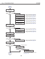
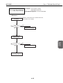
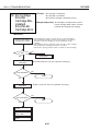
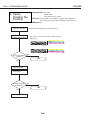
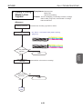
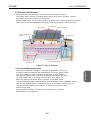
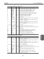
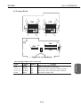
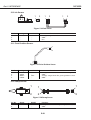
1
REVISION 0 OCT. 1999 QY8-1368-000 COPYRIGHT 1999 CANON INC. CANON BJC-6500 1099 SE 0.30-0 PRINTED IN JAPAN (IMPRIME AU JAPON) 1099 SE 0.30-0 Target Readers This manual is published by Canon Inc. for qualified persons and contains the necessary technical information for technical theory, installation, maintenance, and repair of products. This manual covers all localities where the products are sold. For this reason, it may contain information that does not apply to your locality. Revisions This manual may include technical inaccuracies or typographical errors due to improvements or changes in the products. When amendments are made to the content of this manual, Canon will issue technical information as the need arises. In the event of major alterations to the content of this manual over a long or short period, Canon will publish a revised version of the manual. The following paragraphs do not apply to any countries where such provisions are inconsistent with local law. Trademarks The product names and company names appearing in this manual are the registered trademarks or trademarks of the individual companies. Copyright This manual is copyrighted and all rights reserved. Under the copyright laws, this manual may not be copied, reproduced, or translated into other languages, in whole or in part, without the express written consent of Canon Inc. except in the case of internal business use. Copyright 1999 by Canon Inc. CANON INC. BJ Products Quality Support Dept. 16-1, Shimonoge 3-chome, Takatsu-ku, Kawasaki-shi, Kanagawa 213, Japan This manual was produced on an Apple Macintosh Power Mac 9600/233 personal computer and Apple LaserWriter II NTX-J laser beam printer; final pages were printed on Varityper 5300 with 4000-J RIP. A Canon mo-5001S Magneto-Optical Storage Subsystem with mo-502M Magneto-Optical Storage Disk Cartridge and mo-IF2 interface kit were used for storing large volumes of page layout and graphic data for this manual. All graphics were produced with MACROMEDIA FREEHAND 7.0J. All documents and all page layouts were created with QuarkXPress 3.3J. I. ABOUT THIS MANUAL Part 3: OPERATION This part explains how to operate the unit properly, and how to use the service mode. Part 4: TROUBLESHOOTING This part explains how to resolve problems of the unit, and contains information on how to locate and replace serviceable units and parts. It is divided into two sections: "Troubleshooting by Errors" and "Troubleshooting by Symptoms." Part 5: REFERENCE This part outlines the unit operation giving technical information on hardware, and contains block diagrams, pin assignments, and wiring/circuit diagrams. REF. This manual does not contain complete information required for disassembling and assembling the BJC-6500 printer. Please also refer to the separate Parts Catalog. I MAINTENANCE This part explains maintenance of the unit. It includes precautions and details for disassembly and assembly, and adjustments required when assembling. OPERATION Part 2: MAINTENANCE TROUBLE SHOOTING This part outlines the product and its specifications. REFERENCE Part 1: PRODUCT SPECIFICATIONS PRODUCT SPECIFICATIONS This manual is divided into five parts containing the information required for servicing the BJC-6500 printer. II. TABLE OF CONTENTS Page 1- 1 1- 1 1- 2 1- 3 1- 3 1- 3 1- 4 1- 4 1- 4 1- 4 1- 4 1- 5 1- 6 1 6 1- 7 1 7 1 7 1- 8 1- 9 1 -10 1 11 Part 1: PRODUCT SPECIFICATIONS 1. PRODUCT OUTLINE 1.1 Product Outline 1.2 Features 2. SPECIFICATIONS 2.1 General Specifications 2.1.1 Printer specifications 2.1.2 Product life 2.2 Paper Specifications 2.2.1 Paper sizes 2.2.2 Paper type/settings 2.2.3 Printable area 2.3 BJ Cartridge Specifications 2.4 Scanner Cartridge Specifications 2.4.1 Scannable area 2.5 Interface Specifiocations 2.5.1 Parallel interface 2.5.2 Serial interface 2.6 Printer Driver/Scanner Driver Types 3. PRINTER PACKING 4. NAMES OF PARTS AND THEIR FUNCTIONS 5. PRODUCT CODE LIST Part 2: MAINTENANCE 2- 1 2- 1 2- 1 2- 2 2- 2 2- 3 2- 3 2- 4 2- 5 2- 5 2- 6 2- 6 2- 6 2- 7 2- 8 2- 8 2- 9 2- 9 2 -10 2 -11 2 -11 2 -12 2 -13 2 -13 2 -14 2 -16 2 -18 2 -18 1. PERIODICAL REPLACEMENT/MAINTENANCE 1.1 Parts for Periodical Replacement 1.2 List of Periodical Maintenance 2. DISASSEMBLY AND REASSEMBLY 2.1 List of Tools 2.2 Precautions for Disassembly and Reassembly 2.2.1 Precautions for ink stains (ink paths/ink mist) 2.2.2 Precautions for damage due to static electricity 2.2.3 Precautions for transporting the printer 2.2.4 Precautions on spur tip deformation 2.3 Disassembling and Reassembling the Printer 2.3.1 Unlocking the carriage 2.3.2 Reinstalling tap screws 2.3.3 Removing the printer unit 2.3.4 Removing the ASF unit 2.3.5 Removing the adjustable bushings supporting the carriage shaft 2.3.6 Paper feed gear handling 2.3.7 Spur holder assembly installation 2.3.8 Grease application points 2.4 Adjustment/Setting Procedures 2.4.1 Adjustments (item, adjustment points, tools) 2.4.2 When to perform print head position adjustment 2.4.3 When to reset the EEPROM 2.4.4 How and when to adjust the carriage belt tension 2.4.5 How to adjust the ASF gear position 2.4.6 How to adjust the head gap 3. CONFIRMATION OF OPERATION 3.1 Confirmation Methods II 2 -19 2 -19 4. TRANSPORTING THE PRINTER 4.1 Procedures for Packing the Printer for Transportation Page 3- 1 3- 1 3- 2 3- 4 3- 5 3- 5 3- 6 3- 6 3- 6 3- 8 3- 8 3- 9 3 -10 3 -11 3 -11 3 -11 3 -11 3 -11 Part 3: OPERATION 1. FUNCTIONS RELATED TO PRINTER OPERATION 1.1 Status Display 1.1.1 Status display via the indicator 1.1.2 Status display via the BJ status monitor 1.2 Operations from the Computer 1.2.1 Function settings using the printer driver 1.3 Operations from the Printer 1.3.1 Cleaning 1.3.2 Nozzle check pattern printing 2. SERVICE FUNCTIONS 2.1 Service Mode Operations 2.2 Printing the Service/Factory Test Print 2.3 Printing the EEPROM Information 2.4 Resetting the EEPROM 2.5 Setting the Model 2.6 Checking the Presence of Ink 2.7 Conducting the Print Head Position Adjustment 2.8 Powering Off and Locking the Carriage Part 4: TROUBLESHOOTING 4- 1 4- 1 4- 5 4- 6 4 -19 4 -19 1. TROUBLESHOOTING BY DISPLAYED ERRORS 1.1 Initial Flowchart 1.2 Error Indications (Indicator, Beeper, Error Code) 1.3 Troubleshooting by Errors 2. TROUBLESHOOTING BY SYMPTOMS 2.1 Troubleshooting by Symptoms III Page 5- 1 5- 1 5- 2 5- 3 5- 4 5- 5 5- 5 5- 6 5- 6 5 -11 5 -14 5 -15 5 -16 5 -16 5 -17 5 -17 5 -17 5 -18 5 -18 5 -18 5 -19 5 -19 5 -19 5 -19 5 -19 5 -19 5 -20 5 -20 Part 5: REFERENCE 1. TECHNICAL REFERENCE 1.1 Functions of the Paper Feed Unit 1.2 Construction of the Paper Feed Unit 1.3 Form Alignment Function 1.4 Transmission Gear Unit 1.5 Detection with Sensors 1.6 BJ Cartridge Indenrification 2. CONNECTOR POSITIONS AND PIN ASSIGNMENT 2.1 Control Board 2.2 Carriage Board 2.3 BJ Cartridge 2.4 Scanner Cartridge (Optional) 2.5 AC Adapter 2.6 DC Power Supply Cable 2.7 Carriage Motor 2.8 Paper Feed Motor 2.9 Paper End Sensor 2.10 Ink Sensor 2.11 Print Position Sensor 2.12 Pump Sensor 3. INSTALLATION 3.1 Installation 3.1.1 Installation location 3.2 Installation Procedures 3.2.1 Connecting the interface cable 3.2.2 Connecting the power supply 4. MISCELLANEOUS 4.1 Similarities and Differences to the BJC-6100 IV III. ILLUSTRATION INDEX Page 1- 1 1- 5 1- 6 1- 9 1 -10 Part 1: PRODUCT SPECIFICATIONS Figure Figure Figure Figure Figure 11111- 1 2 3 4 5 Printer Appearance Printable Area Scannable Area Packaging Names of Parts and Their Functions Part 2: MAINTENANCE 2- 3 2- 4 2- 5 2- 5 2- 6 2- 7 2- 8 2- 8 2- 9 2- 9 2 -10 2 -12 2 -13 2 -14 2 -15 2 -16 2 -17 Figure Figure Figure Figure Figure Figure Figure Figure Figure Figure Figure Figure Figure Figure Figure Figure Figure 22222222222222222- 1 2 3 4 5 6 7 8 9 10 11 12 13 14 15 16 17 Ink Paths Ink Mist Capping Position Spur Unit Unlocking the Carriage Removing the Printer Unit Removing the ASF Unit Adjustable Bushings Supporting the Carriage Shaft Paper Feed Gears Spur Holder Ass'y Installation Grease Points Print Position Adjustment Pattern Carriage Belt Tension Adjustment ASF Gear Position Adjustment 1 ASF Gear Position Adjustment 2 Head Gap Adjustment 1 Head Gap Adjustment 2 Part 3: OPERATIONS 3- 1 3- 4 3- 5 3- 7 3- 9 3 -10 3 -11 Figure Figure Figure Figure Figure Figure Figure 3333333- 1 2 3 4 5 6 7 Operation Panel BJ Status Monitor (Sample) Printer Driver Utility (Sample) Nozzle Check Pattern Print (Sample for Black/Color Cartridge) Service/Factory Test Print EEPROM Information Print (Sample) Checking for Presence of Ink V Part 5: REFERENCE 5- 1 5- 2 5- 3 5- 3 5- 4 5- 4 5- 5 5- 6 5- 6 5 -11 5 -14 5 -15 5 -16 5 -16 5 -17 5 -17 5 -17 5 -18 5 -18 5 -18 5 -19 Figure Figure Figure Figure Figure Figure Figure Figure Figure Figure Figure Figure Figure Figure Figure Figure Figure Figure Figure Figure Figure 555555555555555555555- 1 2 3 4 5 6 7 8 9 10 11 12 13 14 15 16 17 18 19 20 21 Paper Feed Path Paper Pick-up Unit Form Alignment Function Form Alignment Function On/Off Drive Switching Unit Operation of the Drive Switching Unit Sensor Positions Control Board Block Diagram Carriage Board BJ Cartridge Scanner Cartridge AC Adapter DC power Supply Cable Carriage Motor Paper Feed Motor Paper End Sensor Ink Sensor Print Position Sensor Pump Sensor Printer Dimensions VI IV. TABLE INDEX Page 3- 2 Part 3: OPERATION TABLE 3- 1 STATUS DISPLAY VIA THE INDICATOR Part 4: TROUBLESHOOTING 4- 5 TABLE 4- 1 ERROR INDICATIONS VII Part 1 PRODUCT SPECIFICATIONS Page 1- 1 1- 1 1- 2 1- 3 1- 3 1- 4 1- 4 1 6 1- 7 1- 8 1- 9 1 -10 1 11 1. PRODUCT OUTLINE 1.1 Product Outline 1.2 Features 2. SPECIFICATIONS 2.1 General Specifications 2.2 Paper Specifications 2.3 BJ Cartridge Specifications 2.4 Scanner Cartridge 2.5 Interface Specifications 2.6 Printer Driver Types 3. PRINTER PACKING 4. NAMES OF PARTS AND THEIR FUNCTIONS 5. PRODUCT CODE LIST Part 1: PRODUCT SPECIFICATIONS BJC-6500 1. PRODUCT OUTLINE This printer is a BJC-6100 leveraged printer, attaining high performance in a businessuse setting. It supports on A3 size paper, and utilizes the BJC-6100 printer engine to achieve high-speed/high-quality printing. Operation Panel Paper Support Paper Guide Auto Sheet Feeder Front Cover Paper Selector Lever Parallel Interface Connector Paper Output Tray USB Interface Connector Paper Thickness Lever SB-30 Cartridge Container BC-30 BC-31 BC-32 Photo BJ Cartridges IS-32 Scanner Cartridge Figure 1-1 Printer Appearance 1-1 PRODUCT SPECIFICATIONS 1.1 Product Outline Part 1: PRODUCT SPECIFICATIONS BJC-6500 1.2 Features This printer differs from the BJC-6100 in the following ways: 1. Supported paper size has increased from A4 to A3 2. Automatic Form Alignment Function (improves skew control) n/a→built-in For details, refer to Part 5: REFERENCE (Page 5-20). Other functions remain commonly shared with the BJC-6100, as follows. • Laser-printer quality using pigment black ink • Dual-cartridge system High quality printing at high speed from a combination of the Black and Color cartridges or the Color and Photo cartridges Black BJ cartridge: Drop modulation, replaceable ink tank (pigment black), 160 nozzle head Color BJ cartridge: Drop modulation, individually replaceable ink tanks (yellow, magenta and cyan), 144 in-line nozzle head (48 nozzles for each of three colors) Photo BJ cartridge: Drop modulation, individually replaceable ink tanks (dye black, photo-magenta and photo-cyan), 144 in-line nozzle head (48 nozzles for each of three colors) • Individually replaceable ink tanks for high cost performance Black ink tanks: Pigment black ink tank Color ink tanks: Yellow, magenta, and cyan ink tanks Photo ink tanks: Dye black, magenta, and cyan ink tanks Ink-out detection, and translucent ink tanks for easier ink level checking • High speed printing (9.0 PPM black printing or 6.0 PPM color printing in HS mode) 1440 x 720 dpi high resolution printing • Automatic printing position adjustment Ensures accurate printing position regardless of cartridges being used or carriage movement direction • Supports a wide variety of print media • Blue Angel compliant • USB and IEEE 1284 compatible 8-bit parallel interfaces. • Optional scanner cartridge with maximum readout resolution of 720×720 dpi also available. 1-2 Part 1: PRODUCT SPECIFICATIONS BJC-6500 2. SPECIFICATIONS 2.1.1 Printer specifications Desktop serial color bubble-jet printer Automatic sheet feeder (no manual feed) 1440dpi x 720dpi (maximum resolution) HS HQ Fine BC-30 + BC-31 Black Text (PC Magazine) 8.0ppm 6.5ppm ... Black (New Black) 9ppm 7.1ppm ... Color (New Color) 6ppm 4.6ppm ... BC-32Photo + BC-31 Photo ... ... 0.17ppm Printing direction HS mode: Bi-directional HQ mode: (360dpi x 360dpi): Bi-directional Fine mode (720dpi x 720dpi): Uni-directional Fine mode (1440dpi x 720dpi): Uni-directional Printing width 289.6mm Line feed speed HQ, HS mode 4 "/S Interface IEEE 1284-compatible 8-bit parallel interface (Compatible/nibble/ECP), USB Automatic sheet feeder capacity Plain paper: 10 mm max. stacking height (about 100 sheets of 64 g/m2 paper) High-resolution paper: 10 mm max. stacking height (about 80 sheets of Highresolution paper) Detection functions Cover open: Yes Paper detection: Yes BJ cartridge installed: Yes Ink-out : Yes Print position detection: Yes Waste ink amount: Yes BJ cartridge identification: Yes Paper width detection: No Pick-up roller position: Yes Acoustic noise during operation Approx. 48 dB / HQ mode (Sound pressure level: compliant with ISO9296) Environmental conditions Operating: 5 to 35°C (41 to 95° F), 10 to 90% RH (no condensation) Storage: 0 to 35°C (32 to 95° F), 5 to 95% RH (no condensation) Power consumption Operating Standby Approx. 30 W max. Approx. 3 W max. External dimensions 574 mm W x 328mm D x 205 mm H Weight 6.8 kg, including BJ cartridges Certification Electromagnetic radiance: VDE0871 CLASS B, CISPR PUBLICATION '22 Electrical safety: Energy Star, IEC950, AS, GS, FIMCO, SEMCO, SISIR, Electrical Safety Regulations of Korea, CCIB (China), CE Mark, EI, MEMCO Environmental regulations: Energy Star, Blue Angel Serial No. location On the printer frame (visible when the front cover is open) Type Paper feeding method Resolution Throughput 1-3 PRODUCT SPECIFICATIONS 2.1 General Specifications Part 1: PRODUCT SPECIFICATIONS BJC-6500 2.1.2 Product life The print quality can be assured during the product life given below, if the specified maintenance is conducted. (1) Monochrome printing 60,000 sheets (1500 ANK character pattern) OR, (2) Color printing 12,000 sheets (7.5% duty per color pattern) OR, (3) 5 years (from the start of use), whichever comes first 2.2 Paper Specifications 2.2.1 Paper sizes (1) Paper size A5, A4, A3 (V), B5, B4 (V), Letter, Legal, A4+, Letter+, Envelope Com #10/DL, Other (100 x 100 ~ 297 x 584mm) (2) Paper weight Automatic Sheet Feeder: 64 ~ 105 g/m2 2.2.2 Paper type/settings Paper Type Paper selector lever position Plain paper (64 g/m2) Approx. 10mm or less Back (Approx. 100 sheets) Color BJ paper LC-301 Approx. 10mm or less Back High-resolution HR-101 Approx. 10mm or less Back paper (Approx. 80 sheets) Glossy photo paper GP-301 1 sheet (portrait) Forward Glossy photo film HG-201 1 sheet Forward OHP film CF-102 30 sheets or less Back Back print film BF-102 10 sheets or less Back BJ cloth FS-101 1 sheet Forward Banner paper BP-101 1 sheet Forward T-shirt transfer TR-201 1 sheet Forward Glossy photo card FM-101 1 sheet Forward Envelope Com. #10 10 sheets or less Forward DL (portrait) Thick paper 1 sheet Forward CAUTION Stacked in the ASF Paper thickness lever position Up Up Up Up Up Up Up Down Down Down Up Down Down If the Paper Selector Lever/Paper Thickness Lever are incorrectly set for the paper used, paper feeding or printing problems may occur. For details on the lever positions, refer to Part 1: PRODUCT SPECIFICATIONS (Page 1-10). 2.2.3 Printable area Refer to Figure 1-2 Printable Area. 1-4 Part 1: PRODUCT SPECIFICATIONS BJC-6500 Color BJ cartridge Separate ink tank 144 nozzles, in-line (48 nozzles x 3) Inks: Pigment black C, M, Y Cartridge life: Approx. 5000 pages* Approx. 3000 pages** Ink tank: Black C, M, Y Ink tank life: Approx. 500 pages* Approx. 280 pages** Cartridge weight: Approx. 60 g Approx. 60 g (w/o ink tank) Construction: Print head: Black BJ cartridge Separate ink tank 160 nozzles, in-line * Monochrome printing ** Color printing Photo BJ cartridge Separate ink tank 144 nozzles in-line (48 nozzles x 3) Photo-Bk, Photo-C, Photo-M Approx. 3000 pages** Photo-Bk, Photo-C, Photo-M Approx. 280 pages** Approx. 60 g (1500-character, HQ mode) (7.5% duty, HQ mode) A3, A4, A5 and B5 sizes Letter (LTR) and legal (LGL) (1) 18.5mm (2) 26.5mm 3mm (1) 18.5mm (2) 26.5mm 3mm (2) 27.0mm (1) 22.5mm 5.0mm 3.4mm 3.4mm (2) 27.0mm (1) 22.5mm 5.0mm 6.4mm 6.4mm A4+ and letter+ (LTR+) sizes 27.94mm 29.21mm sizes Envelope 3.0mm 29.21mm 27.94mm 5.0mm 5.08mm 6.4mm A4+ 5.88mm ***+ 5.08mm : Recommended printing area (1) Monochrome printing : Printable area (2) Color or photo printing Figure 1-2 Printable Area 1-5 6.4mm PRODUCT SPECIFICATIONS 2.3 BJ Cartridge Specifications Part 1: PRODUCT SPECIFICATIONS BJC-6500 2.4 Scanner Cartridge Specifications Name Type Resolution (dpi) Image sensor Light source Scanning method/direction Document feeding method IS-32 Cartridge replacement type color scanner 90×90, 180×180, 300×360, 360×360, 720×720 Single-line, 256 pixel CCD RGB (R; Red, G; Green, B; Blue) Sequential RGB light source switching method Place the document into the scanning holder and feed it through ASF 10 bit input, 8 bit output 5/12 V Approx 30 W (90 dpi, monochrome), SW (stand by) ECP/Nibble Approx. 41 mm W × 90 mm D × 77 mm H Approx. 100 g Raise the paper selector lever on the printer upward when scanning Scannable paper thickness: 0.25 mm or less Gradation Input voltage Power consumption Interface External dimensions Weight Others 2.4.1 Scannable area Place the image to scan in the scanning holder with the upper left corner fitted to the placement point. Holder Type SH-101 (220 x 327 mm) Size (width x height) 105 x 148 mm 148 x 210 mm 210 x 297 mm 182 x 257 mm 8.5 x 11 inch 297 x 420 mm 11 x 17 inch 8.5 x 14 inch 257 x 364 mm Paper A6 A5 A4 B5 Letter A3 Ledger Legal B4 SH-102 (300 x 458 mm) Scannable area (width x height) 98.2 x 138 mm 141.2 x 200 mm 203.2 x 287 mm 175.2 x 247 mm 208.2 x 269.4 mm 289 x 410 mm 272.6 x 421.8 mm 208.2 x 332.6 mm 250.2 x 354 mm 3.4mm 6mm 32mm Placement point Recommended scanning area 23mm Scanning holder : Scannable Area Figure 1-3 Scannable Area 1-6 Part 1: PRODUCT SPECIFICATIONS BJC-6500 1) Interface type IEEE 1284 compatible parallel interface 2) Data transfer 8-bit parallel interface (supports nibble/ECP modes) 3) Signal voltage levels Input: "Low" level: 0.0V to +0.8V "High" level: +2.4V to +5.0V Output: "Low" level: 0.0V to +0.8V "High" level: +2.4V to +5.25V 4) Input/output Each signal pulled up with +5V 5) Interface cable Twisted-pair double shielded cable, shorter than 2.0m IEEE 1284 compatible required Material: AWG No. 28 or higher (AWG: American Wire Gauge) 6) Interface connector Printer-side Amphenol 57-40360 (or equivalent) Cable-side Amphenol 57-30360 (or equivalent) 7) Input/output signal and pin arrangements Refer to Part 5: 2. CONNECTOR POSITIONS AND PIN ASSIGNMENT (Page 5-6) for details. 2.5.2 Serial interface 1) Interface type USB Interface (Universal Serial Bus; USB Specification Release Number 1.10) 2) Data transfer Control transfer method Bulk transfer method 3) Signal voltage level Input: Input difference sensitivity: +0.2V (Max) Common-mode difference: +0.8V to +2.5V Output: Static output high: +2.8V to 3.6V Static output low: less than +0.3V 4) Input/output Each signal pulled up with 3.3V 5) Interface cable Twisted-pair shielded cable USB standard compatible required Material AWG No.28, Data pair (AWG: American Wire Gauge) AWG No.20 to No.28, Power distribution pair 6) Interface connector Printer-side USB standard, Series B receptacle Cable-side USB standard, Series B plug 7) Input/output signal and pin arrangements Refer to Part 5: 2. CONNECTOR POSITIONS AND PIN ASSIGNMENT (Page 5-6) for details. 1-7 PRODUCT SPECIFICATIONS 2.5 Interface Specifications 2.5.1 Parallel interface Part 1: PRODUCT SPECIFICATIONS BJC-6500 2.6 Printer Driver / Scanner Driver Types For support of dual interfaces (USB and Centronics) and scanner, 6 drivers are prepared. Windows: BJ Raster driver for Windows 95 / 98*1 BJ Raster driver for Windows NT 4.0*1 BJ Raster driver for Windows 2000*1 Scanner driver for Windows 95 /98 NT 4.0 (Windows 2000 not supported) *1 Macintosh: BJ printer driver for Macintosh Scanner driver for Macintosh Available combinations of interface and driver under each OS are given in the table below. OS Windows 95 / 98 Windows NT 4.0 Windows 2000 Macintosh For use of the printer (BJ Raster driver) Parallel interface USB interface *2 For use of the scanner (Scanner driver) Parallel interface*3 USB interface *2 : Usable. : Usable on condition. : Not usable *1: At installation of the driver, select either parallel or USB according to the cable connected. *2: Correct operation is guaranteed only for Windows 98 pre-installed computers, though the USB interface may operate under Windows 95. *3: The parallel interface operates in the nibble or ECP modes. 1-8 Part 1: PRODUCT SPECIFICATIONS BJC-6500 3. PRINTER PACKING Set Up Software & Reference Guide Quick Start Guide Read This First Paper Output Tray User's Guide Paper Support Ink Tanks Packing Printer Packing Cartridge Container BJ Cartridges Packing Packing Tape Figure 1-4 Packaging 1-9 PRODUCT SPECIFICATIONS After opening the printer box, confirm that all items below are included. Part 1: PRODUCT SPECIFICATIONS BJC-6500 4. NAMES OF PARTS AND THEIR FUNCTIONS The names of the printer parts, and their functions are as shown below. Paper Guide Lightly press this guide against the left side of paper sheets to align them. Paper Support Extend this paper rest to support larger sized paper. Front Cover Open this cover when replacing BJ cartridges or, clearing paper-jams. Auto Sheet Feeder Paper Selector Lever By moving the lever back or forward, the paper feed method ( to use or not use the ASF unit's claws ) is selected. Here the lever is in the forward position. POWER button Press this button to power on or off the printer. RESUME button After correcting a problem, press this button to make the printer ready. Paper Output Tray Allows smooth ejection of paper and reduces paper friction. Indicator Paper Thickness Selector Lever Use this selector to adjust the gap between the print head and the paper for different paper types. Set it to the uppermost position for normal plain paper. Operation Panel Not lit when powered off. When lit in green, the printer is ready to print. When lit or blinking in orange, an error has occurred, and the printer cannot print. Cartridge Lock Lever Use this lever to secure the BJ cartridges to the carriage. Raise it to remove the BJ cartridge. Interface Connectors Connects to the interface cable from the computer. Two types of connector interface, USB and parallel, are provided. Carriage The left side of the carriage holds the Black or Photo BJ cartridge, and the right side hold the Color BJ cartridge. Figure 1-5 Names of Parts and Their Functions 1-10 Part 1: PRODUCT SPECIFICATIONS BJC-6500 5. PRODUCT CODE LIST Item Printer BJ cartridge Ink tank Cartridge container Scanner cartridge Name BJC-6500 Black Color Photo Black Cyan Magenta Yellow Photo Black Photo Cyan Photo Magenta - Scanning holder for A4, LTR Scanning Holder Scanning holder for A3, LDR Scanning Holder 1-11 Product code Q30-3300 Q30-3182 BC-30 F45-1471 BC-31 F45-1491 BC-32 Photo F45-1511 BCI-3BK F47-2171 BCI-3C F47-2181 BCI-3M F47-2191 BCI-3Y F47-2201 BCI-3PBK Photo F47-2231 BCI-3PC Photo F47-2211 BCI-3PM Photo F47-2221 SB-30 Q70-4040 IS-32 Q70-4070 SH-101 SH-102 Q70-3640 Q70-4140 PRODUCT SPECIFICATIONS The product codes for the printer, consumables, and options are shown in TABLE 1-1. Part 1: PRODUCT SPECIFICATIONS BJC-6500 This page intentionally left blank 1-12 Part 2 MAINTENANCE Page 2- 1 2- 1 2- 1 2- 2 2- 2 2- 3 2- 6 2 -11 2 -18 2 -18 2 -19 2 -19 1. PERIODICAL REPLACEMENT/MAINTENANCE 1.1 Parts for Periodical Replacement 1.2 List of Periodical Maintenance 2. DISASSEMBLY AND REASSEMBLY 2.1 List of Tools 2.2 Precautions for Disassembly and Reassembly 2.3 Disassembling and Reassembling the Printer 2.4 Adjustment/Setting Procedures 3. CONFIRMATION OF OPERATION 3.1 Confirmation Methods 4. TRANSPORTING THE PRINTER 4.1 Procedures for Packing the Printer for Transportation Part 2: MAINTENANCE BJC-6500 1. PERIODICAL REPLACEMENT / MAINTENANCE 1.1 Parts for Periodical Replacement Level User Service personnel Parts for periodical replacement None None Consumable Black BJ cartridge Color BJ cartridge Photo BJ cartridge Black ink tank for the Black BJ cartridge Cyan, magenta, and yellow ink tanks for the Color BJ cartridge Photo cyan, photo magenta, and photo black ink tanks for the Photo BJ cartridge Scanner cartridge (Optional) None 1.2 List of Periodical Maintenance Level User Service personnel Location None None 2-1 MAINTENANCE Level User Service personnel Part 2: MAINTENANCE BJC-6500 2. DISASSEMBLY AND REASSEMBLY 2.1 List of Tools Ordinary Tools Phillips screwdriver Phillips screwdriver (about 38 mm long) Blade screwdriver Long-nose pliers Tweezers Flat brush Oil applicator Multimeter Paperclip (diameter 1.27 mm) Special Tools (part no.) 1.9-mm gap gauge (QY9-0038-000) 0.5-mm gap gauge (QY9-0001-000) Tension spring (QY9-0052-000) Lock pin (QY9-0053-000) MOLYKOTE PG-641 grease (CK-0562-000) FLOIL 946P grease (QY9-0045-000) Note For removing and replacing screws For removing and replacing screws for the control board For removing plastic parts For removing and replacing springs For removing and installing flexible cables For applying grease (one per grease type) For applying FLOIL 946P For troubleshooting Substitute for Lock Pin QY9-0053 Note One for head gap adjustment (see Page 2-17) One for head gap adjustment (see Page 2-17) For carriage belt tension adjustment (see Page 2-13) For matching gear-phase of the ASF drive switching unit (see Page 2-15) For application to specified locations (see Page 2-10) For application to specified locations (see Page 2-10) 2-2 Part 2: MAINTENANCE BJC-6500 2.2 Precautions for Disassembly and Reassembly 2.2.1 Precautions for ink stains (ink paths/ink mist) CAUTION The ink is not harmful to the human body, but contains some organic solvents: The black ink contains glycerin 56-81-5 and diethylene glycol 111-46-6. The yellow ink contains glycerin 56-81-5 and isopropyl alcohol 67-63-0. The cyan, magenta, photo-cyan, photo-magenta and photo-black ink contain glycerin 56-81-5, isopropyl alcohol 67-63-0, ethylene glycol 10721-1, and diethylene glycol 111-46-6. Be careful not to get the ink into your mouth or eyes. If the ink gets into your eyes, wash with plenty of water and consult a doctor. In case you have swallowed a large amount of ink, consult a doctor immediately.The ink contains dyes. If clothing is stained with the ink, the ink may not be removed completely. Maintenance Jet Receiving Section n Ta BJ Cartridges Wiper Head Cap Waste Ink Absorber Figure 2-1 Ink Paths 2-3 MAINTENANCE Be careful not to touch the ink paths. Ink on hands could stain the printer, work table, or clothes. The ink paths include the BJ cartridge ink tank outlet, the BJ cartridge ink filters and nozzles, the maintenance jet receiving section, the head caps, the wipers, and the waste ink absorber. Part 2: MAINTENANCE BJC-6500 The BJ cartridge ejects ink onto the paper during printing. After the printer is used for a long period or used heavily, ink mist bouncing back from the paper could accumulate and contaminate the platen (including the left and right paper guide plates), front cover, as well as the periphery of the purge unit. Carefully wipe off the ink mist with a dampened soft cloth so that hands or clothing will not be stained by contaminated parts during servicing. Front Cover Platen Figure 2-2 Ink Mist 2.2.2 Precautions for damage due to static electricity Static electricity may be generated by your clothes rubbing against each other and may accumulate in your body. If you touch electrical elements, the discharge of static electricity could damage them or change their electrical characteristics. For this reason, avoid touching the ink sensor contacts or the printer's BJ cartridge contacts. 2-4 Part 2: MAINTENANCE BJC-6500 2.2.3 Precautions for transporting the printer Tape Figure 2-3 Capping Position 2.2.4 Precautions on spur tip deformation Take care not to bend the tips of the spurs. The tips of the spurs make contact with printed paper and are contaminated with ink, but due to their small surface contact area, the tips, cleaned by the spur cleaners, will not stain the printed paper. However, if the tips are bent and their contact surface area increases, they collect more ink and are not easily cleaned by the spur cleaners, and thereby stain the printed paper by making dotted lines on it. Spurs Figure 2-4 Spur Unit 2-5 MAINTENANCE When turned off by the POWER button, the BJ cartridges are capped and the carriage is locked in place at the capping position by the lock arm. When the printer cannot be powered off by the POWER button for transportation, etc., move the carriage to the capping position by hand and secure it with tape before transporting the printer. Part 2: MAINTENANCE BJC-6500 2.3 Disassembling and Reassembling the Printer Note the following when disassembling or reassembling the printer. When disassembling or reassembling the printer, refer to the parts catalog. The numbers in the parts catalog illustrations indicate the disassembly sequence. 2.3.1 Unlocking the carriage When the printer is shipped from the factory (or when the cartridges are installed and the power has been turned off normally), the carriage is locked in the capping position to secure the cartridges during transportation. When the printer is powered on properly, the carriage locking is disabled automatically. If the printer cannot be powered on normally, it will be necessary to manually unlock the carriage. This can be done by turning the paper eject roller gear half a turn (5 indented notches) in the direction of arrow 2 with a flat-blade screwdriver while gently pressing the carriage in the direction of arrow 1. You can also use the carriage key to turn the paper eject roller gear. 2 1 Paper Eject Roller Gear Figure 2-5 Unlocking the Carriage 2.3.2 Reinstalling tap screws The printer unit is secured to the base with tap screws. Once tap screws have been removed, pieces of the molding remain attached to the screw threads. Reinstalling the tap screws in this condition can damage the screw threads. To prevent this, when reinstalling screws, where possible, new screws should be used. 2-6 Part 2: MAINTENANCE BJC-6500 2.3.3 Removing the printer unit MAINTENANCE Refer to Figure 5 (page B-9) of the Parts Catalog. 1) As shown in 3), to easily release the tab by the carriage motor, pull the cable upwards. 2) Set the paper thickness lever to its lowest position (envelope position). 3) Press the locking tab on the right side of the printer in the direction of arrow 1 and slide the printer unit in the direction of arrow 2, resting it on the boss. 4) Likewise, release the locking tab on the left side of the printer and rest the left side of the printer unit on its' boss. 5) To avoid catching the paper thickness selector lever on the base unit, hold the printer unit by the handles on the left and right, tilt the printer unit in the direction of arrow 3, and lift upwards to remove the unit. 3 3 1 2 Figure 2-6 Removing the Printer Unit 2-7 Part 2: MAINTENANCE BJC-6500 2.3.4 Removing the ASF unit The ASF unit is attached to the printer unit such that the ASF driving gear and the pick-up roller are matched in phase. Once you have removed the assembly screws, painted red to protect against careless removal, which fasten the ASF unit to the printer frame, you must readjust the position of the ASF gear with respect to that of the pick-up roller. For details, refer to 2.4.5 How to adjust the ASF gear position (Page 214). Assembly Screw (Red) ASF Unit Assembly Screws (Red) Figure 2-7 Removing the ASF Unit 2.3.5 Removing the adjustable bushings supporting the carriage shaft The adjustable bushings supporting the carriage shaft are adjusted and secured to the printer frame so that the ideal head-to-paper gap is maintained for best print quality. Once you have loosened the screws, painted red to protect against careless removal, which fasten the adjustable bushings to the printer frame, you must readjust the position of the bushings for head gap adjustment. For details, refer to 2.4.6 How to adjust the head gap (Page 2-16). Adjustable Bushing Supporting the Carriage Shaft Adjustable Bushing Supporting the Carriage Shaft Figure 2-8 Adjustable Bushings Supporting the Carriage Shaft 2-8 Part 2: MAINTENANCE BJC-6500 2.3.6 Paper feed gear handling Eject Roller Gear Feed Roller Gear Figure 2-9 Paper Feed Gears 2.3.7 Spur holder assembly installation Because removing and installing the spur holder ass'y affects the head gap, be sure to perform the following procedures when installing the spur holder ass'y. (1) By hand, pinch the spur holder ass'y and chassis together, and tighten the center screw (1). (2) Similarly, tighten the left and right screws (2, 3). (3) Then tighten the remaining 2 screws in the upper unit. 3 Spur Holder Ass'y 1 2 Figure 2-10 Spur Holder Ass'y Installation 2-9 MAINTENANCE Be careful not to touch the gears (eject roller's, feed roller's) in the paper feed unit, especially the paper feed gear, during disassembly or reassembly, because even slight damage to it could affect paper feeding when printing at high resolution. Part 2: MAINTENANCE BJC-6500 2.3.8 Grease application points Apply greases at the points shown below. Apply a thin film of grease using the flat brush. For the Carriage Oil Pad, do not use a brush but apply directly. For disassembly and reassembly procedures, refer to the parts catalog. CAUTION Do not apply more than the specified amount of grease, especially to the grease pad. If grease gets on the wipers or caps, damage is likely to occur. Cam Sliding Surface Approx. 24 mg (Molykote PG-641) Grease Pad Approx. 0.6 cc (Floil 946P) Cam Sliding Surface Approx. 24 mg (Molykote PG-641) Eject Roller Gear Teeth (apply to all teeth evenly) Approx. 60 mg (Molykote PG-641) Carriage Guide Frame Sliding Surface (apply the proper amount of grease so as not to drip) (Floil 946P) Feed Roller Gear Teeth (apply to all teeth evenly) Approx. 96 mg (Molykote PG-641) Carriage Guide Frame Back Surface (apply a thin coat of grease over the entire surface) Approx. 48 mg (Molykote PG-641) Paper Thickness Lever Sliding Surface Approx. 12 mg (Molykote PG-641) Slow-Down Gear Teeth (apply to all teeth evenly) Approx. 72 mg (Molykote PG-641) Feed Roller Sliding Surface Approx. 12 mg (Molykote PG-641) Feed Roller Sliding Surface Approx. 12 mg (Molykote PG-641) Paper Thickness Lever Spring Sliding Surface Approx. 12 mg (Molykote PG-641) Figure 2-11 Grease Points 2-10 Part 2: MAINTENANCE BJC-6500 2.4 Adjustment/Setting Procedures 2.4.1 Adjustments (item, adjustment points, tools) Time 2 min. (2) Service personnel level Item Adjustment point Reinstalling the ASF ASF gear position adjustment (Page 2-14) Reinstalling the Idler Pulley Carriage belt tension (Page 2-13) Control Board replacement Resetting the EEPROM Waste Ink Absorber (Page 2-13) replacement Carriage unit related parts Print head position adjustment replacement or disassembly (Page 2-12) Loosening of head-paper screw Head gap (Page 2-16) 2-11 Tools 1 sheet of B5-sized or larger paper. Time 2 min. Tools (Page 2-2) Lock pin or paperclip 1 min. Tension spring 1 min. None 2 min. 1 sheet of B5-sized or larger paper Gap gauge 5 min. MAINTENANCE (1) User Level Item Adjustment point BJ Cartridge Print head position adjustment (Page 2-12) Part 2: MAINTENANCE BJC-6500 2.4.2 When to perform print head position adjustment As there are two BJ cartridges installed in this printer, even a slight difference in size or seating position between them may result in inaccurate dot placement, and thereby poor printing. To correct this, after installing the BJ cartridges, perform the automatic print head position adjustment, one of the utilities the printer driver package provides. If a computer is not available, you can still perform the print head position adjustment in service mode. For the procedures, refer to Part 3: 2.1 Service Mode Operations (Page 3-8). Set at least one sheet of B5 (or larger) plain paper in the ASF, and select the print head position alignment pattern in the test print area of the printer driver's Utility sheet. LED calibration 360-dpi vertical alignment adjustment 360-dpi bi-directional rough adjustment 360-dpi bi-directional fine adjustment 180-dpi bi-directional rough adjustment 180-dpi bi-directional fine adjustment 360-dpi horizontal alignment forward rough adjustment 360-dpi horizontal alignment forward fine adjustment 360-dpi horizontal alignment reverse rough adjustment 360-dpi horizontal alignment reverse fine adjustment 180-dpi horizontal alignment forward rough adjustment 180-dpi horizontal alignment forward fine adjustment 180-dpi horizontal alignment reverse rough adjustment 180-dpi horizontal alignment reverse fine adjustment 720-dpi horizontal alignment forward rough adjustment 720-dpi horizontal alignment forward fine adjustment 1440-dpi horizontal alignment forward rough adjustment 1440-dpi horizontal alignment forward fine adjustment Printing position check pattern Figure 2-12 Print Position Adjustment Pattern CAUTION When printing the print head position adjustment pattern, do not use paper smaller than B5-sized paper. Use paper of B5 size or larger for the nozzle check pattern printing. If you use smaller paper, the platen may be smeared with ink. 2-12 Part 2: MAINTENANCE BJC-6500 2.4.3 When to reset the EEPROM 1) On replacement of the control board. Upon replacement of the control board, visually check the waste ink absorber's ink level and replace if it is more than 7% filled, and reset the EEPROM. If the EEPROM is not reset, waste ink could leak before the printer issues the waste ink full warning. Since the EEPROM data of a replacement control board is not defined, you must always set the model. 2) On replacement of the waste ink absorbers. The EEPROM's waste ink counter should be cleared, or the EEPROM reset. CAUTION NOTE Previous EEPROM data cannot be confirmed with the test printing once the EEPROM has been reset. Always perform a test print before resetting the EEPROM, as all information such as function status, number of sheets passed, waste ink amount, etc., except for the model setting, will be lost when the EEPROM is reset. It is not possible to write data (such as waste ink amount, model, etc.) of the old EEPROM to the EEPROM of a replacement control board The waste ink full error should not occur before the life of the printer has been reached. However, frequently powering on/off, replacing the BJ cartridge, opening the front cover (automatic cleaning), or usage conditions may cause this error to occur earlier. 2.4.4 How and when to adjust the carriage belt tension When the carriage belt tension has been loosened to replace the carriage, or for other reasons, insert the tension spring (QY9-0052-000) in the correct position to adjust the belt tension, and fix the idler pulley assembly by tightening the fixing screws, and remove the tension spring. Tension Spring Fixing Screws Idler Pulley Carriage Belt Figure 2-13 Carriage Belt Tension Adjustment 2-13 MAINTENANCE The EEPROM (IC11) on the control board stores total amount of waste ink absorbed, function settings, and other information specific to the printer. Due to this, in the following situations, it will be necessary set the model or reset the EEPROM For details, refer to Part 3: 2.1 Service Mode Operations (Page 3-8). Part 2: MAINTENANCE BJC-6500 2.4.5 How to adjust the ASF gear position The ASF gear position adjustment matches the phasing of the ASF pick-up roller and ASF drive switching gear. For this reason, the initial positions of the ASF gear and the ASF drive gear must be aligned. Preparation: 1) Reassemble the ASF unit components to the level as when the ASF unit was detached. Adjustment procedure: 1) Slowly turn the ASF drive gear by finger in the direction of the arrow. 2) Stop turning when the gear "clicks" (becomes easy to turn). (To confirm the position, gently move the ASF drive gear up and down). 3) If the gear has passed the initial position, continue turning the gear in the same direction to return to the correct position. 4) Turn the pick-up roller so that the ASF cam is positioned as shown in the diagram. 5) Align the ASF gear 1 and the ASF unit's protruding mark as shown in the diagram. ASF Drive Gear Protruding Mark Cam ASF Gear 1 Figure 2-14 ASF Gear Position Adjustment 1 2-14 Part 2: MAINTENANCE BJC-6500 MAINTENANCE Adjustment procedure: 1) To prevent the gear position from changing, press a finger against the gear and fix the ASF unit to the chassis, by tightening the screws. By hooking the claw of the upper ASF to the chassis, smoothly lower the ASF to install it. 2) Turn ASF gear 1 in the direction of the arrow in the amount of 1 gear tooth. 3) To hold ASF gear 1 in place, insert the lock pin (QY9-0053) into the lock pin hole. Be sure to pass the pin through ASF gear 1 and into the hole in the ASF base. 4) Attach ASF gear 2. 5) Secure ASF gear 2 to the ASF unit with the Bushing (QB-4150-000). 6) Remove the lock pin from the ASF unit. Amount of 1 Gear Tooth ASF Gear 1 Lock Pin Hole ASF Upper Unit Claw Lock Pin Bushing ASF Gear 2 Figure 2-15 ASF Gear Position Adjustment 2 CAUTION Do not insert the lock pin into the lock pin hole before the ASF unit is secured to the chassis. By doing so, the gears cannot be matched in phase. 2-15 Part 2: MAINTENANCE BJC-6500 2.4.6 How to adjust the head gap Preparation: 1) Reassemble to the level the top cover is to be put on next. 2) Raise both the right and left adjustable bushings supporting the carriage shaft as shown by arrow 1, and temporarily fix the bushings in that position using the fixing screws. 3) Remove the right and left shaft clips from the carriage shaft. 4) Set the paper thickness selector to the lowest position (thick paper position) CAUTION Ensure that the gap gauges are clean and not deformed. Also ensure that the platen is clean. Adjustable Bushing Supporting the Carriage Shaft (right) Fixing Screw (red) Carriage Belt Adjustable Bushing Supporting the Carriage Shaft (left) Fixing Screw (red) 1 Shaft Clip Lever Paper Thickness Normal Paper Position Black BJ Cartridge Thick Paper Position Figure 2-16 Head Gap Adjustment 1 2-16 Adjustment procedure: 1) Set the 1.9-mm gap gauge (QY9-0038) in position A. 2) Move the carriage into position C by moving the carriage belt by hand. 3) Install the Black BJ cartridge on the left side of the carriage. 4) Loosen, by half a turn, the fixing screw locking the carriage shaft's left adjustable bushing, move the paper thickness lever up/down 2 or 3 times, and tighten the fixing screw. 5) Remove the Black BJ cartridge. 6) Stack the 0.5mm gap gauge (QY9-0001) and the 1.9mm gap gauge (QY9-0038) together in position B. 7) Set the paper thickness lever to the lowest position (thick paper position). 8) Move the carriage into position D by moving the carriage belt by hand. 9) Install the Black BJ cartridge on the left side of the carriage. 10) Loosen, by half a turn, the fixing screw locking the carriage shaft's right adjustable bushing, move the paper thickness lever up/down 2 or 3 times, and tighten the fixing screw. 11) Remove the Black BJ cartridge. 12) Repeat steps 1) to 11) again before continuing to 13). 13) Firmly tighten the right and left fixing screws. 14) Reinstall the right and left shaft clips in place. Position A Position B QY9-0038 QY9-0001 QY9-0038 Black BJ Cartridge Carriage Chassis Position D Position C Figure 2-17 Head Gap Adjustment 2 2-17 MAINTENANCE Part 2: MAINTENANCE BJC-6500 Part 2: MAINTENANCE BJC-6500 3. CONFIRMATION OF OPERATION 3.1 Confirmation Methods Confirming the operation of the printer after reassembly is possible by conducting the following procedures: 1) Offline, perform the print head position adjustment. Confirm that the print head position adjustment can be performed. For procedures, refer to Part 3: 2.1 Service Mode Operations (Page 3-8). 2) Offline, perform the service/factory test print. Confirm that the printing is correctly performed and that after 1) that misalignment does not appear. For procedures, refer to Part 3: 2.1 Service Mode Operations (Page 38). After replacing either the control board or the waste ink absorber, in addition to 1) and 2), it is necessary to confirm the following: On replacement of the: Control board Waste ink absorber Confirm that: On the service/factory test print, that the ROM version and model name are correct, and that the number of sheets passed and the total waste ink amount have been cleared. On the service/factory test print, that the total waste ink amount has been cleared. 2-18 Part 2: MAINTENANCE BJC-6500 4. TRANSPORTING THE PRINTER To prevent the ink from leaking or drying out in the nozzles during transportation, keep BJ cartridges installed in the printer, capped, or stored in the cartridge container. Refer to Part 2: 2.2.3 Precautions for transporting the printer (Page 2-5). To prevent ink leakage, transport the printer with the ink tanks installed in the BJ cartridge. Transport the printer (for service or return) with the carriage locked in place. When transporting the printer, follow the procedures below: 1) Press the POWER button to turn off the printer. After the printer moves the carriage to the home position and locks the carriage in place, the indicator will go out. Or, by entering the Service Mode and pressing the RESUME button, the printer will power off after locking the carriage. For details, refer to (Part 3: 2.8 Powering Off and Locking the Carriage Page 3-11). 2) Disconnect the interface cable. 3) Unplug the power cord from the wall outlet. 4) Open the front cover and visually confirm that the carriage is locked in the capping position (on the right side of printer). If the carriage is not in the capping position, move it manually to the capping position by using the carriage belt, and secure it there with tape. 5) Secure the cartridge lock lever in place with tape. 6) Close the cover. 7) Pack the printer in its' original packing in its' original carton. If the original packing materials are not available, wrap the printer with sufficient shock absorbing material. CAUTION Do not unplug the printer before switching off the printer with the POWER button, otherwise, the BJ cartridges' nozzles will not be capped, which may result in ink leaking or drying-out. Do not carry a BJ cartridge and its ink tanks separately. 2-19 MAINTENANCE 4.1 Procedures for Packing the Printer for Transportation Part 2: MAINTENANCE BJC-6500 This page intentionally left blank 2-20 Part 3 OPERATION Page 3- 1 3- 1 3- 5 3- 6 3- 8 3- 8 3- 9 3 -10 3 -11 3 -11 3 -11 3 -11 3 -11 1. FUNCTIONS RELATED TO PRINTER OPERATION 1.1 Status Display 1.2 Operations from the Computer 1.3 Operations from the Printer 2. SERVICE FUNCTIONS 2.1 Service Mode Operations 2.2 Printing the Service/Factory Test Print 2.3 Printing the EEPROM Information 2.4 Resetting the EEPROM 2.5 Setting the Model 2.6 Checking the Presence of Ink 2.7 Conducting the Print Head Position Adjustment 2.8 Powering Off and Locking the Carriage Part 3: OPERATION BJC-6500 1. FUNCTIONS RELATED TO PRINTER OPERATION For the BJC-6500, functions for printer operation such as display of the status, operation from the computer, and operation from the printer itself, are built-in. 1.1 Status Display The printer displays the status via the indicator lamp and the beeper. The number of times the indicator flashes and the beeper beeps are used to determine the error status. POWER Button RESUME Button Figure 3-1 Operation Panel 3-1 OPERATION Indicator Part 3: OPERATION BJC-6500 1.1.1 Status display via the indicator Display of the status via the indicator is as shown in Table 3-1 below. TABLE 3-1 STATUS DISPLAY VIA THE INDICATOR Normal operation Status Indicator When powered-on During power-on During power-off While resetting During cleaning Service/Factory test printing Front cover open During printing Lights in Green Blinks in Green Blinks in Green Blinks in Green Blinks in Green Blinks in Green Blinks in Green Blinks in Green When in error Error Indicator [Recoverable by user] Paper feed error Paper jam error Ink out error BJ Cartridge mis-installed error No BJ cartridge error BJ Cartridge error Waste ink warning error Head position adjustment error Lights Lights Lights Lights Lights Lights Lights Lights [Unrecoverable by user] ROM error RAM error EEPROM error Home position error Printer temperature sensor error Waste ink full error Head temperature error Head temperature sensor error Cartridge displaced error ASF sensor error [Internal errors] Ink sensor error in in in in in in in in Beeps Error code ... ... ... ... ... ... ... ... ... ... ... ... ... ... ... ... Beeps Orange Orange Orange Orange Orange Orange Orange Orange 2 3 4 5 6 7 8 9 10 10 10 10 10 10 10 10 10 10 times times times times times times times times times times No indication None ... ... ... ... ... ... ... Error Reference code page times times times times times times times times Blinks in Orange 1 time Blinks in Orange 2 times Blinks in Orange 3 times Blinks in Orange 4 times Blinks in Orange 5 times Blinks in Orange 6 times Blinks in Orange 7 times Blinks in Orange 8 times Blinks in Orange 9 times Blinks in Orange 10 times Reference page 6800 5100 5400 5B00 5200 5200 5600 5700 Page Page Page Page Page Page Page Page 4-13 4-13 4-15 4-16 4-16 4-16 4-6 4-17 Page Page Page Page Page Page Page Page Page Page 4-6 4-6 4-6 4-7 4-6 4-6 4-10 4-10 4-11 4-12 5910 Page 4-18 Note: Internal errors are not displayed, but can be checked by printing the EEPROM information. See (Page 3-10) 3-2 Description of Error Indications Errors recoverable by users: 1) Paper feed error Paper feed operation fails to feed paper. 2) Paper jam error Paper eject operation of 23 inches fails to eject the paper. 3) Ink out error The indicated ink tank is out of ink (ink chamber and sponge). 4) BJ Cartridge mis-installed error The BJ cartridges are not installed in their correct positions. 5) No BJ cartridge error One or both of the BJ cartridges are not installed. The scanner cartridge is installed in the color (right) cartridge side. 6) BJ Cartridge error One or both of the BJ cartridges are defective (unreadable ID, or out-of-range rank). 7) Waste ink warning The amount (stored in EEPROM) of waste ink absorbed is at 95% of the defined capacity. 8) Head position adjustment error The automatic head position adjustment has failed. Errors unrecoverable by users: 9) ROM error ROM checking during initialization is NG. 10) RAM error RAM checking during initialization is NG. 11) EEPROM error Writing to EEPROM has failed. 12) Home position error The home position sensor is defective (broken circuit) or fails to detect home position. 13) Temperature sensor error The thermal sensor (TH1) on the logic board is defective (broken circuit). 14) Waste ink full error The amount (stored in EEPROM) of waste ink absorbed is at 100% of the defined capacity. 15) Head temperature error The inside temperature of the BJ cartridge is too high. This error should occur earlier than the head temperature sensor error. 16) Head temperature sensor error The thermal sensor in the BJ cartridge is defective. 17) Cartridge displaced error The printer cannot detect the BJ cartridge when the carriage is out of the cartridge replacement position. 18) ASF sensor error The pick-up roller doesn't turn during paper feeding, or the pick-up roller doesn't detect the pick-up roller's flag. 19) Ink sensor error During the ink sensor check at initialization, it will be reported that there is ink, even when there is none. Ink checking is only performed at power-on during initialization, and it will be reported that there is ink. As this error is not displayed, it can be checked on the EEPROM information printout in the error history section. 3-3 OPERATION Part 3: OPERATION BJC-6500 Part 3: OPERATION BJC-6500 1.1.2 Status display via the BJ status monitor The BJ status monitor window shows the printer's conditions and print-job progress. Print-jobs can be cancelled from this window. (1) Main functions of the BJ status monitor 1) Show the printer's conditions and progress in real-time by means of graphics and messages. 2) Display error types and show recommended recovery methods. 3) Show the types of the BJ cartridges installed and the ink-out warnings of ink tanks by icon and name. 4) Abort the current print-job. (2) Items displayed on the BJ status monitor 1) Printer designation 2) Document name 3) Printer conditions (including error codes and recommended recovery methods) 4) Date and time of print start 5) Progress status: 6) Number of pages printed 7) Print-job abortion 8) BJ cartridge identification (icons graphically display the types and positions of installed BJ cartridges, and the ink-out warnings of ink tanks) Figure 3-2 BJ Status Monitor (Sample) 3-4 Part 3: OPERATION BJC-6500 1.2 Operations from the Computer As this printer has no physical function selectors, function settings can be set by using the Canon printer driver. The printer driver's utility menu allows such operations and function settings as listed below. In the menu, you can also invoke a special custom menu by, while pressing the shift key, selecting Custom Settings. 1) Cleaning 2) Head refreshing 3) Nozzle check pattern printing (Test Print) 4) Head position adjustment (Print Head Alignment) 5) Printer power off 6) Automatic power setting 7) Launching the status monitor 8) Custom settings · Enable ECP mode (disabled by default) · Enable high speed printing (enabled by default): Printer's response time (ACKNLG) is changed from 4 to 0.9 ms. · Enable pause-between-pages (disabled by default) · Enable pause-between-scanning (disabled by default) · Enable automatic head position adjustment following BJ cartridge replacement (disabled by default) · Manually conduct the print head position adjustment (disabled by default) <In the special custom menu (special-custom/service mode)> · Economy cleaning (disabled by default): Cleaning operation at power up is omitted if the printer has been switched off for less than 72 hours. Enabling this function is useful for saving ink, especially when the printer's power is provided through the computer (possibility of nozzle clogging increases). · Smear control (enabled by default): When smear control is enabled, smearing of ink on paper due to paper-to-paper contact is prevented. Smear control is useful for high duty printing on normal plain paper or post cards. When smear control is disabled (with printed sheets collected directly following printing), throughput increases. Figure 3-3 Printer Driver Utility (Sample) 3-5 OPERATION 1.2.1 Function settings using the printer driver Part 3: OPERATION BJC-6500 1.3 Operations from the Printer This printer has operations which can be performed independent of the computer. With the printer powered on, hold down the RESUME button and confirm the specified number of beeps for the desired action, and then release the RESUME button. Operations Cleaning Nozzle check pattern printing Number of beeps 1 time 2 times Remarks ... Prints one sheet and ends 1.3.1 Cleaning With the printer powered on, hold down the RESUME button and after confirming one beep, release the RESUME button. The cleaning operation will start, cleaning both (right and left) print heads. If you want to clean only one print head, connect the printer to the computer, and perform the print-head cleaning from the computer using the printer driver utility. 1.3.2 Nozzle check pattern printing With the printer powered on, hold down the RESUME button and after confirming two beeps, release the RESUME button. The nozzle check pattern printing will start, feeding a sheet, which must be of B5 size or larger from the auto sheet feeder and print a standard pattern using all nozzles of both installed BJ cartridges. If print defects are detected in the test print, perform print-head cleaning. If five or more cleaning operations fail to solve the problem, replace the BJ cartridge with a new one. CAUTION Use paper of B5 size or larger for the nozzle check pattern printing. If you use smaller paper, the platen may be smeared with ink. NOTE To abort the nozzle check pattern printing, press the POWER button. The printer will switch itself off after ejecting the paper. 3-6 Part 3: OPERATION BJC-6500 Black BJ Cartridge Color BJ Cartridge Printed with the first nozzle Large dot printing Printed with the first nozzle Yellow 48 nozzles Cyan 48 nozzles Magenta 48 nozzles Black 160 nozzles Printed with the 48th nozzle Printed with the 160th nozzle Small-dot printing Printed with the first nozzle Printed with the first nozzle Printed with the 48th nozzle Printed with the 160th nozzle (Y) 180-dpi horizontal forward direction (X1) 180-dpi horizontal reverse direction (X2) 360-dpi horizontal forward direction (X3) 360-dpi horizontal reverse direction (X4) 720-dpi horizontal forward direction (X5) 720-dpi horizontal reverse direction (X6) 180-dpi bi-directional (B1) 360-dpi bi-directional (B2) OPERATION 360-dpi vertical Figure 3-4 Nozzle Check Pattern Print (Sample for Black/Color Cartridge) 3-7 Part 3: OPERATION BJC-6500 2. SERVICE FUNCTIONS This printer has a service mode for service-related settings or performing test printing. The operator panel buttons are used to enter service mode. 2.1 Service Mode Operations 1) With the printer powered off, while pressing the RESUME button, press and hold the POWER button. The buzzer will sound once. 2) While holding down the POWER button, release the RESUME button. Press the RESUME button twice in succession, and then release the POWER button. (Each time the RESUME button is pushed, the buzzer will sound once.) The indicator will blink in green, and then light in green. 3) Select one of the following service mode functions by pressing the RESUME button the specified number of times. Press 0 times 1 time 2 times Indicator Lights in Green Lights in Orange Lights in Green 3 4 5 6 Lights Lights Lights Lights times times times times 7 times or more in in in in Functions Service/factory test print EEPROM information printing EEPROM initializing (reset to default settings, but model setting is not cleared) Waste ink counter clear Model setting Presence of ink information printing Print head position adjustment operations Power off/Locking the Carriage Orange Green Orange Green Lights in Orange 4) Execute the function you have selected by pressing the POWER button. The buzzer will sound once. The printer will switch off itself after performing the function. CAUTION Use the Black and Color BJ cartridges for the service/factory test printing. It is not possible to enter Service Mode without cartridges installed. (Also, the Photo and Color BJ cartridges cannot be used for service/factory test printing.) If you have changed the model setting, perform the service/factory test printing for confirmation. 3-8 Part 3: OPERATION BJC-6500 2.2 Printing the Service/Factory Test Print The service/factory test print displays, in the header portion, such information as the control ROM version, model setting, total sheets passed, and total waste ink absorbed. Currently installed left and right cartridges Model ROM version Total number of pages passed when using Scanner cartridge Total number of pages passed when using Photo / Color cartridges Total number of pages passed when using Black / Color cartridges Not Used Not Used ROM Ver Vx.xx BJF-6000 Use Head <BC-xx,BC-xx> HeadTemp0=xxx.x HeadTemp1=xxx.x EnvironmentTemp=xxx.x Bk=xxxxx Cl=xxxxx Ph=xxxxx Sc=xxxxx ScCl=xxxxx Factory Area=xx xx xx xx xx xx xx xx LostInkCount =xx.x% Destination =xx USBSerialNo =xxxxxx Total waste ink amount (absorption ratio of the waste ink absorber : % ) Figure 3-5 Service/Factory Test Print * : USB Serial Number A USB serial number will be assigned, in conformance with USB standards, so that each printer can be identified when multiple printers are connected to a host computer via USB interface. A unique value is recorded in the EEPROM when the control board is manufactured. The USB serial number recorded in the EEPROM will not be cleared even when the EEPROM is reset. Also, it cannot be overwritten with any value. 3-9 OPERATION Serial number when using USB* Part 3: OPERATION BJC-6500 2.3 Printing the EEPROM Information The EEPROM stores such information as function settings, total sheets passed with the Black/Color or Photo/Color cartridges, total waste ink absorbed, and records the last three errors recoverable only by service personnel. The information stored in the EEPROM is printed out as a hexadecimal dump in the EEPROM information print. The EEPROM information is useful especially for knowing how heavily the printer has been used. - EEPROM Information <Hex.> Address +0 +1 +2 +3 +4 00000000 05 20 00 0A 00 00000010 00 00 00 00 2A 00000020 35 6C B7 AB 33 00000030 14 00 0A 07 04 00000040 04 90 00 08 00 00000050 00 00 00 00 00 00000060 00 00 00 1D 00 00000070 00 00 00 00 00 00000080 00 00 00 72 00 00000090 3C 00 00 10 10 000000A0 0C 04 00 08 00 000000B0 00 00 00 00 04 000000C0 00 00 00 00 15 000000D0 04 19 57 AB 98 000000E0 35 36 30 30 35 000000F0 00 00 00 D6 67 Error record 1 +5 00 6A BC 02 00 00 58 00 00 0C 0C 04 0B 1A 31 7C +6 B8 51 E9 02 00 04 00 00 00 0C 0C 00 BB 72 30 73 +7 83 A1 71 02 44 44 1B 08 2E 08 00 00 19 13 30 FF Error record 2 +8 00 38 32 00 00 00 00 00 00 0C FD 00 35 00 35 01 +9 0C 54 DD 00 00 00 01 00 00 10 07 00 1A 45 31 FF +A 9F AA 02 00 00 00 00 00 00 0C 00 00 D5 93 30 FF +B 40 A0 0C 00 44 00 2F 08 30 0C 00 00 C6 6B 30 FF +C 09 1E 00 0A 00 00 00 00 83 0C 04 00 13 46 FF FF +D 35 16 00 80 00 00 06 00 00 10 04 00 0A 34 FF FF +E 1C DA 00 00 00 02 00 00 00 0C 00 00 46 63 FF FF +F 28 3C 00 00 44 B9 00 08 00 0C 00 00 61 E3 F0 FF Error record 3 Figure 3-6 EEPROM Information Print (Sample) Error records are displayed in ASCII code for the last 3 errors, except for ROM/RAM errors, that are recoverble only by service personnel, with the most recent error firs and the oldest error last. Errors EEPROM error Home position error Temperature sensor error Waste ink full error Head temperature error Head temperature sensor error Cartridge displaced error Ink sensor error ASF sensor error Error code ASCII code representation 6800 5100 5400 5B00 5200 5200 5600 5910 5700 36 35 35 35 35 35 35 35 35 3-10 38 30 30 31 30 30 34 30 30 42 30 30 32 30 30 32 30 30 36 30 30 39 31 30 37 30 30 Part 3: OPERATION BJC-6500 2.4 Resetting the EEPROM The EEPROM stores such information as function settings, total sheets passed with the Black/Color or Photo/Color cartridges, total waste ink absorbed, and the last three errors recoverable only by service personnel. Because the waste ink full error is based on the data of the total waste ink absorbed as stored in the EEPROM, the Waste Ink Counter must be cleared whenever the waste ink absorber has been replaced. If the control board has been replaced, the new EEPROM must also be initialized and the waste ink absorber replaced. 2.5 Setting the Model Times Indicator Model 0 times Lights in Green BJ F6100 1 time Lights in Orange BJC-6500 2 times or more ... BJC-XXXX (reserved for OEM) After setting the model, perform the service/factory test printing for confirmation. 2.6 Checking the Presence of Ink When this function is enabled, the printer will check for ink in the ink storage chamber, and print out the results. This function can be used to confirm correct operation of the Ink Sensor. (1) Install an ink tank (with an empty ink storage chamber) into the Color BJ cartridge. (2) Select this function, and print out the results. (3) Confirm that a value of "0" is returned for the empty ink tank. Yellow, Magenta, Cyan Ink Tanks Black Ink Tank ExistInkY = 0 ExistInkM = 1 ExistInkC = 0 ExistInkm = 1 ExistInkc = 1 ExistInkK = 0 03F1,03F1,03F1,03F1,03F1,03F1 Photo-Magenta, Photo-Cyan, Photo-Black Ink Tanks Figure 3-7 Checking for Presence of Ink 2.7 Conducting the Print Head Position Adjustment The print head position adjustment can be performed off-line (without being connected to a computer). The printer will perform the print head position adjustment in the same way as if the user initiated the adjustment from the computer via the printer driver utility. 2.8 Powering Off and Locking the Carriage When this function is enabled, regardless of whether BJ cartridges are installed in the carriage, the printer will move the carriage to the home position and, after locking the carriage, power off. When transporting the printer for service when no BJ cartridge is present, in order to lock the carriage, this function can be used. (1) Enter Service Mode. (2) Press the RESUME button 7 times. (3) Open the front cover and remove the BJ cartridge(s). (4) Press the POWER button. 3-11 OPERATION The control board of this printer is a common component for different printers. If you have replaced the control board, it is necessary to set the model setting as initial information. After selecting the model, by pressing the POWER button, the selection will be validated. (Each time the RESUME button is pressed, the beeper will sound once.) Part 3: OPERATION BJC-6500 This page intentionally left blank 3-12 Part 4 TROUBLE SHOOTING Page 4- 1 4- 1 4- 5 4- 6 4 -19 4 -19 1. TROUBLESHOOTING BY DISPLAYED ERRORS 1.1 Initial Flowchart 1.2 Error Indications (Indicator, Beeper, Error Code) 1.3 Troubleshooting by Errors 2. TROUBLESHOOTING BY SYMPTOMS 2.1 Troubleshooting by Symptoms Part 4: TROUBLESHOOTING BJC-6500 1. TROUBLESHOOTING BY DISPLAYED ERRORS 1.1 Initial Flowchart Plug in the AC cord • The printer is supplied with AC power. MPU/printer controller initialization ROM check Ink sensor/waste ink full/printer temperature sensor (TH1) check Ink sensor error • Error not displayed (See page 4-18) Read EEPROM Turn power on • The POWER button is pressed. One beep Indicator blinks To next page 4-1 TROUBLE SHOOTING DRAM check Part 4: TROUBLESHOOTING BJC-6500 From previous page Error check OK? No Yes EEPROM error • 10 beeps, indicator blinks in orange 3 times (See page 4-6) ROM error • 10 beeps, indicator blinks in orange 1 time (See page 4-6) RAM error • 10 beeps, indicator blinks in orange 2 times (See page 4-6) Waste ink full error • 10 beeps, indicator blinks in orange 6 times (See page 4-6) Printer temperature sensor error • 10 beeps, indicator blinks in orange 5 times (See page 4-6) Head temperature error • 10 beeps, indicator blinks in orange 7 times (See page 4-10) Head temperature sensor error • 10 beeps, indicator blinks in orange 8 times (See page 4-10) Home position error • 10 beeps, indicator blinks in orange 4 times (See page 4-7) Diode sensor check OK? No Yes Carriage unlocked Home position check OK? No Yes Check for paper OK? Yes No • Check for paper Paper ejected Check for paper Yes Paper jam error • 3 beeps, indicator blinks in orange (See page 4-13) To next page 4-2 Part 4: TROUBLESHOOTING BJC-6500 From previous page ASF sensor check • Pick-up roller initialization No OK? Yes ASF sensor error BJ cartridge check • 10 beeps, indicator blinks in orange. 10 times (See page 4-12) No OK? Check for open cover Open/closed Closed Cleaning TROUBLE SHOOTING Yes • Is the cover open? Open Carriage moves to cartridge replacement position BJ cartridge misinstalled error • Cartridge installed • Cartridge not detected • Cartridge not installed correctly • 5 beeps, indicator lights in orang (See page 4-16) No BJ cartridge error • 6 beeps, indicator lights in orange (See page 4-16) BJ cartridge error • 7 beeps, indicator lights in orange (See page 4-16) To next page 4-3 Part 4: TROUBLESHOOTING BJC-6500 From previous page Ink sensor check OK? Ink sensor error I/F busy disabled END 4-4 • Error not displayed (See page 4-18) Part 4: TROUBLESHOOTING BJC-6500 1.2 Error Indications (Indicator, Beeper, Error Code) TABLE 4-1 ERROR INDICATIONS [Recoverable by user] Paper feed error Paper jam error Ink out error BJ cartridge mis-installed error No BJ cartridge error BJ cartridge error Waste ink warning error Head position adjustment error [Unrecoverable by user] ROM error RAM error EEPROM error Home position error Printer Temperature sensor error Waste ink full error Head temperature error Head temperature sensor error Cartridge displaced error ASF sensor error [Internal errors] Ink sensor error Indicator Beeps Lights Lights Lights Lights Lights Lights Lights Lights in in in in in in in in Orange Orange Orange Orange Orange Orange Orange Orange Blinks Blinks Blinks Blinks Blinks Blinks Blinks Blinks Blinks Blinks in in in in in in in in in in Orange Orange Orange Orange Orange Orange Orange Orange Orange Orange No indication 2 3 4 5 6 7 8 9 1 time 2 times 3 times 4 times 5 times 6 times 7 times 8 times 9 times 10 times Error Reference code page times times times times times times times times 10 10 10 10 10 10 10 10 10 10 times times times times times times times times times times None 6800 5100 5400 5B00 5200 5200 5600 5700 Page Page Page Page Page Page Page Page 4-13 4-13 4-15 4-16 4-16 4-16 4-6 4-17 Page Page Page Page Page Page Page Page Page Page 4-6 4-6 4-6 4-7 4-6 4-6 4-10 4-10 4-11 4-12 5910 Page 4-18 Note: Internal errors are not displayed, but can be checked by printing the EEPROM information (Page 3-10). *1 The Waste Ink Warning error can be recovered by pressing the RESUME button. 4-5 TROUBLE SHOOTING Errors Part 4: TROUBLESHOOTING BJC-6500 1.3 Troubleshooting by Errors 1. ROM Error <Cause> ROM cannot be read during initialization. <Suspected parts> Control ROM <Measure> Replace the ROM or control board. 2. RAM Error <Cause> RAM cannot be read or written. <Suspected parts> DRAM, printer controller <Measure> Replace the control board. 3. EEPROM Error <Cause> EEPROM cannot be written. <Suspected parts> EEPROM, printer controller <Measure> Replace the control board. CAUTION Error indications may fail if the ROM or RAM error occurs. 4. Printer Temperature Sensor Error 5. Waste Ink Full Error/Waste Ink Warning <Cause> The thermistor is defective. <Suspected parts> Thermistor (TH1) <Measure> Replace the control board. <Cause> The calculated amount of waste ink absorbed is 100% or 95% of the capacity of the waste ink absorber. <Suspected parts> Waste ink absorber, control board <Measure> 1. Reset the EEPROM/replace the waste ink absorber. 2. Replace the control board. 4-6 Part 4: TROUBLESHOOTING BJC-6500 <Cause> The home position sensor fails to detect the home 6. Home Position Error position. <Suspected parts> Home position sensor, carriage motor, paper feed motor, control board, carriage ribbon cable, carriage board, and DC power supply cable <Measure> Visual check OK? • Check for paper jams, carriage belt wear/degradation/displacement, bent carriage guide frame, and guide shaft damage/bending. • Move the carriage by hand and check for smoothness and unusual noise. • Is the carriage ribbon cable free of creasing? No Repair or replace faulty part Yes Open the cover and switch on OK? Yes Visually check the carriage's motion. TROUBLE SHOOTING Check the carriage for smooth motion No Check the carriage motor 1 4 Measurement points Normal value CN402 1-3 Approx. 3 Pin No. 2-4 Disconnect the carriage motor cable from the control board before checking. No OK? Replace the carriage motor Yes To page 4-9 (1) To next page 4-7 Part 4: TROUBLESHOOTING BJC-6500 From previous page Visually check operation of paper feed unit OK? No Check the paper feed motor Yes 1 4 Measurement points Normal value 1-3 CN403 2-4 Approx. 3 Pin Disconnect the paper feed motor cable from the control board before checking. No OK? Replace the paper feed motor Yes To page 4-9 (1) Visually check that carriage is unlocked Unlocked? Yes Visually check that carriage is unlocked. No 1. Replace the ASF drive gear unit 2. Replace the purge unit 1. Replace the carriage board 2. Replace the carriage ribbon cable Replace with QH2-2364, Carriage Ribbon Cable. 4-8 Part 4: TROUBLESHOOTING BJC-6500 (1) HVCONT check HVCONT (+24 VDC output control for output (J1). +5VDC HVCONT GND +24VDC GND No Replace the control board Yes +24 VDC output check OK? Yes signal) • Check for +24 VDC during operation (J1). • No +24 VDC is output when the carriage is at the cartridge replacement position or if an error occurs. No Replace the AC adapter Replace the DC power supply cable Replace the control board 4-9 TROUBLE SHOOTING OK? Part 4: TROUBLESHOOTING BJC-6500 <Cause> The print head is too hot. 7. Head Temperature Error / Head Temperature Sensor Error Even with power turned off, head temperature doesn't drop. <Suspected parts> BJ cartridge, control board, empty ink tank. <Measure> Check that printing is not being conducted with empty ink tank(s). Visually check ink tanks Empty? Yes No Replace ink tank(s) Leave the printer for several minutes with power off It is possible the BJ cartridge head unit has overheated. Turn power on Error indication? No Yes 1. Replace both BJ cartridges END 2. Replace the control board 4-10 Part 4: TROUBLESHOOTING BJC-6500 <Cause> The BJ cartridge is out of position outside the 8. Cartridge Displaced Error cartridge replacement position. <Suspected parts> BJ cartridge, control board, carriage board, carriage ribbon cable <Measure> Remove and reinstall both BJ cartridges Error indication? No Yes 1. Replace both BJ cartridges END 2. Replace the control board 3. Replace the carriage ribbon cable TROUBLE SHOOTING 4. Replace the carriage board 4-11 Part 4: TROUBLESHOOTING BJC-6500 <Cause> Pick-up roller doesn't turn. 10. ASF Sensor Error LF roller drive switching isn't conducted. <Suspected parts> ASF drive gear unit, control board faulty ASF gear position adjustment, pick-up roller <Measure> • Is the pick-up roller's sensor flag broken or missing? Visually check OK? No Yes Replace pick-up roller Adjust the ASF gear position Reoccurrence of error? Yes • Was the ASF gear position adjustment correctly performed? • Reinstall the ASF, and reconduct the adjustment Part 2: 2.4.5 How to adjust the ASF gear position (See page 2-14) No END 1.Replace the ASF drive gear unit 2.Replace the Control board 4-12 Part 4: TROUBLESHOOTING BJC-6500 <Cause> Paper feed operation fails to feed paper. 9. Paper Feed Error/Paper Jam Error Paper eject operation fails to eject paper. <Suspected parts> Paper feed section, paper end sensor, control board <Measure> Visually check the paper feed unit OK? Check for paper jams, gear deformation/damage/missing teeth. Is the paper selector lever's position correct? No Part 2: 2.2.2 Paper type/settings (See page 1-4) Repair or replace faulty parts Yes Switch on with the cover open OK? Check the paper feed motor, pick-up roller, paper feed roller, and eject roller for movement during initialization. Check for noise. Check the paper feed motor for out-of-step. No Repair or replace faulty parts Yes Repair or replace faulty parts. Replace the control board Paper feed check OK? Yes Check that the pick-up roller rotates and the ASF feeds paper normally. No Check the ASF unit To next page 4-13 Check the pick-up roller's rubber rings and the separation sheet for cleanliness, wear, or degradation. Check the rod cam for engagement. Check the gears for deformation, damage, and phase. TROUBLE SHOOTING Check the operation of paper feed unit Part 4: TROUBLESHOOTING BJC-6500 ASF Feed Path Paper From previous page Paper End Sensor Paper End Sensor Using paper, check the arm for smooth motion, deformation, or damage. Check the paper end sensor's arm OK? No Replace the sensor arm Yes Paper sensor check Measurement points Sensor Normal value J8 Open Low level (paper detected) Pin No. 3 C l o s e High level (no paper detected) With the printer switched ON, check actuation of the paper end sensor's arm using paper. OK? No Replace the control board Yes Visually check the Drive Swiching Unit OK? Yes ASF gear position adjustment Check for displaced gears, missing teeth, and damaged/bent parts. No Replace the Drive Swiching Unit See Part 2: 2.4.5 How to adjust the ASF gear positon (page 2-14). END 4-14 Part 4: TROUBLESHOOTING BJC-6500 <Cause> The ink tank is empty. 11. Ink Out Error EEPROM is defective. <Suspected parts> Ink tank, EEPROM <Measure> Visually check ink tanks Empty? Remove ink tank and confirm that the ink tank is not empty. Yes No Replace ink tank(s) OK? Yes No Reinstall the ink tank Replace the control board 4-15 TROUBLE SHOOTING Reinstall the ink tank securely Part 4: TROUBLESHOOTING BJC-6500 12. BJ Cartridge Error/BJ Cartridge Misinstalled Error/No BJ Cartridge Error <Cause> • BJ cartridge not detected. • BJ cartridge not installed. • BJ Scanner cartridge combination wrong. <Suspected parts> BJ cartridges, carriage board, control board, carriage ribbon cable, contacts between BJ cartridge and carriage <Measure> Visually check that BJ cartridges are installed OK? • Check that the contact section is free of foreign matter. • Check that the Black or Photo BJ cartridge is on the left and the Color BJ cartridge is on the right side of the carriage. • Check the Scanner cartridge is the left side of the carriage. • Check that the cartridge lock lever is locked. • Check the carriage ribbon cable for folds or other damage. No Repair or replace faulty parts Yes Reinstall the BJ cartridges Error indication? Reinstall both the left and right BJ cartridges. No END Yes Replace the BJ cartridges Error indication? Replace both the left and right BJ cartridges. No END Yes 1. Replace the control board 2.Replace the carriage ribbon cable 3.Replace the carriage board. 4-16 Part 4: TROUBLESHOOTING BJC-6500 13. Head Position Adjustment Error <Cause> The head position adjustment has failed. <Suspected parts> BJ cartridge, ink tank, print position sensor, control board, carriage ribbon cable <Measure> Is the automatic head position adjustment pattern correctly printed? No OK? Yes 1. Conduct cleaning 2. Replace the ink tanks • Black/cyan ink tank 3. Replace the BJ cartridges • Black/Color BJ cartridge 1 4 Measurement points Pin No. 1- 2 Pin No. 2- 3 OK? Yes Sensor Normal value ... Approx. 2.0V ... Approx. 2.0V No Replace the print position sensor 1. Replace Replacethe thecarriage 1. carriage board. board 2. Replace the control board 3.Replace the • Replace with QH2-2364 (Carriage Ribbon Cable) cartridge ribbon cable 4-17 TROUBLE SHOOTING Print position sensor check Part 4: TROUBLESHOOTING BJC-6500 <Cause> Ink sensor check does not detect ink out. <Suspected parts> Ink sensor, control board, ink tank 14 Ink Sensor Error <Measure> Visual check Turn the printer off, then on Does error still occur? Yes • Is the ink tank present? • Is it displaced? • Reinstall the ink tank. • Turn the printer off, then on in a location away from intense light. No END 1 3 Ink sensor check Measurement point Pin No. OK? Yes 2-3 1-2 No Replace the ink sensor Replace the control board 4-18 Normal value Approx. 1.2V Approx. 0V Part 4: TROUBLESHOOTING BJC-6500 2. TROUBLESHOOTING BY SYMPTOMS 2.1 Troubleshooting by Symptoms <Symptoms> Pressing the POWER button fails to switch on 1. Power Does Not Turn On. <Cause> the printer. Pressing the POWER button does not start initialization. Defective AC adapter, control board, or DC power supply cable <Measure> Check the AC adapter for +5 Vdc output voltage +5VDC GND Yes No Replace the AC adapter Replace the control board Replace the DC power supply cable 4-19 TROUBLE SHOOTING OK? Part 4: TROUBLESHOOTING BJC-6500 <Symptoms> No prints 2. Faulty Printing: No Printing <Cause> Partial prints No prints for some colors The ink tank, BJ cartridge, or purge unit is defective, the orange cap and/or tape is affixed to the head unit. <Measure> Cleaning operation Perform the cleaning operation 5 times. Print the Nozzle check pattern Do print problems appear ? See Part 3: 1.3.2 Nozzle check pattern printing (page 3-6) No END Yes 1. Replace the relevant ink tank 2. Replace the relevant BJ cartridge Do print problems still appear ? No END Yes Replace the purge unit 4-20 Part 4: TROUBLESHOOTING BJC-6500 3. Faulty Printing: Blank Lines Appear <Symptoms> Blurred prints <Cause> Blank lines Specific dot missing The BJ cartridge(s), BJ cartridge contacts, carriage ribbon cable, purge unit, control board or carriage board is defective. <Measure> Cleaning operation Perform the cleaning operation 5 times. Print the Nozzle check pattern Do print problems appear? See Part 3: 1.3.2 Nozzle check pattern printing (page 3-6) No Reinstall the BJ cartridge Faulty printing still occur? Reinstall the relevant BJ cartridge. No END Yes To next page 4-21 TROUBLE SHOOTING END Yes Part 4: TROUBLESHOOTING BJC-6500 From previous page 1. Replace the relevant ink tank 2. Replace the relevant BJ cartridge Faulty printing still occur? No END Yes 1. Replace the carriage ribbon cable 2. Replace the carriage board 2. Replace the control board No OK? Yes Replace the purge unit END 4-22 Part 4: TROUBLESHOOTING BJC-6500 4. Faulty Printing: Other Symptoms Paper gets dirty Check to see if The platen is contaminated with ink mist. The paper feed unit is contaminated with ink (paper is contaminated before reaching the platen). Measure Wipe clean with a damp cloth. Disassemble the paper feed unit and wipe clean with a damp cloth. Perform test paper feeding several times. Replace the spur unit. The tips of the spurs are deformed. Vertical misalignment The paper thickness selector is Correct the setting. wrongly set (positioned). The printed nozzle check pattern has Readjust printing position. mis-alignment. TROUBLE SHOOTING Spur marks appear 4-23 Part 4: TROUBLESHOOTING BJC-6500 5. Ink Out Resulting in no Error <Symptoms> Ink out results in no error. <Cause> The ink tank is empty, or the control board or ink sensor is defective. <Measure> • Is the ink tank present? • Is it displaced? • Reinstall the ink tank. Visual check • Turn the printer off, then on in a location away from intense light. Turn the printer off, then on Does error still occur? No Yes END 1 Ink sensor check Measurement point Pin No. OK? Yes 2-3 1-2 No Replace the ink sensor Replace the control board 4-24 3 Normal value Approx. 1.2V Approx. 0V Part 5 REFERENCE Page 5- 1 5- 1 5- 2 5- 3 5- 4 5- 5 5- 5 5- 6 5- 6 5 -11 5 -14 5 -15 5 -16 5 -16 5 -17 5 -17 5 -17 5 -18 5 -18 5 -18 5 -19 5 -19 5 -19 5 -20 5 -20 1. TECHNICAL REFERENCE 1.1 Functions of the Paper Feed Unit 1.2 Construction of the Paper Feed Unit 1.3 Form Alignment Function 1.4 Transmission Gear Unit 1.5 Detection with Sensors 1.6 BJ Cartridge Indenrification 2. CONNECTOR POSITIONS AND PIN ASSIGNMENT 2.1 Control Board 2.2 Carriage Board 2.3 BJ Cartridge 2.4 Scanner Cartridge (Optional) 2.5 AC Adapter 2.6 DC Power Supply Cable 2.7 Carriage Motor 2.8 Paper Feed Motor 2.9 Paper End Sensor 2.10 Ink Sensor 2.11 Print Position Sensor 2.12 Pump Sensor 3. INSTALLATION 3.1 Installation 3.2 Installation Procedures 4. MISCELLANEOUS 4.1 Similarities and Differences to the BJC-6100 Part 5: REFERENCE BJC-6500 1. TECHNICAL REFERENCE 1.1 Functions of the Paper Feed Unit The paper feeding function of this printer is to feed the print media from the Auto Sheet Feeder (ASF) through to the print start position. The ASF is driven by the paper feed motor, and automatically feeds the print media. When the print media has been detected by the photo-interrupter type paper end sensor, it is fed to the print start position on the platen via the paper feed rollers. If print media is fed, but not detected by the paper end sensor, a paper feed error will occur. Also, after the paper end sensor has detected the paper and measured the amount of paper fed, if this amount is low, the printer will utilize the paper feed assistance function to reattempt paper feeding. ASF Paper Feed Path Paper Pick-up Roller Paper End Sensor Sensor Flag REFERENCE Pressure Roller Spurs Paper Feed Rollers Eject Rollers Figure 5-1 Paper Feed Path 5-1 Part 5: REFERENCE BJC-6500 1.2 Construction of the Paper Feed Unit The BJC-6500's paper feed unit is comprised of the paper pick-up unit, paper feed unit, and the paper eject unit. Its' construction is different from that of the BJC-6100, as explained below. a) Pick-up unit Pick-up Roller Paper Angled ASF Face Pick-up Separator Pick-up Guide Stacked Paper Plain Paper Feeding (paper selector lever-back) Envelope/Postcard Feeding (paper selector lever-forward) Figure 5-2 Paper Pick-up Unit The pick-up unit of this printer is comprised of the pick-up roller, pick-up guide, the angled ASF face, and two pick-up separators. The pick-up separators are connected to the paper selector lever, and depending on the position of the paper selector lever's setting, the pick-up separators can be raised or lowered. When paper is stacked in the ASF, in order to prevent misfeeding due to bending of the paper, the angled face of the ASF is used to hold the paper in the place. For print media such as plain paper, both corners of the media are held down by the pick-up separators, causing slight bending of the paper to separate the sheets, and the media is fed through to the paper feed rollers one sheet at a time. If the paper is a resilient type, such as envelopes and thick paper, it pushes the paper separator over, and due to the angled face of the ASF, is fed one sheet at a time. While this construction provides better feeding performance, if the paper selector lever is incorrectly positioned, misfeeding or multi-feeding can occur. For details, refer to Part 1: 2.2.2 Paper type/settings (Page1-4) 5-2 Part 5: REFERENCE BJC-6500 1.3 Form Alignment Function In order to improve the paper feeding capability of the BJC-6500, such as reducing skew, the printer has a built-in form alignment function to detect the top of fed media. The form alignment function allows paper to press against the paper feed roller to create a bend in the paper, and this bend forces the leading edge of the paper to become aligned to permit straight-line feeding. The form alignment function is not used, however, when printing in HS mode. Pick-up Roller Pressure Roller Spur Paper Paper Bend Eject Roller Paper Feed Roller ROM Ver Vx.xx BJF-6000 Use Head <BC-xx,BC-xx> HeadTemp0= xxx.x HeadTemp1=xxx.x EnvironmentTemp=xxx.x Bk=xxxxxxxxxx Cl=xxxxxxxxxx Ph=xxxxxxxxxx Factory Area=xx xx xx xx xx xx xx xx LostInkCount =xx.x% Destination =xx Form Alignment Off ROM Ver Vx.xx BJF-6000 Use Head <BC-xx,BC-xx> HeadTemp0=xxx.x HeadTemp1=xxx.x EnvironmentTemp=xxx.x Bk=xxxxxxxxxx Cl=xxxxxxxxxx Ph=xxxxxxxxxx Factory Area=xx xx xx xx xx xx xx xx LostInkCount =xx.x% Destination =xx Form Alignment On Figure 5-4 Form Alignment Function On/Off 5-3 REFERENCE Figure 5-3 Form Alignment Function Part 5: REFERENCE BJC-6500 1.4 Transmission Gear Unit Depending on the carriage position, the transmission gear unit switches the paper feed motor's drive power over to drive the purge unit or the auto-sheet feeder. The slide arm that moves with the carriage action controls the timing of the switching and the operation. Part A Slide Arm Figure 5-5 Drive Switching Unit ASF drive occurs when the slide arm depresses part A. When this occurs, the internal rocker arm applies pressure to engage the ASF drive gears. With the gears engaged, the ASF drive gears rotate, and ASF driving takes place. The ASF gear is controlled by a single rotation clutch, as in the BJC-6100, and after rotating one turn, rotation stops. With the single rotation clutch, when the carriage depresses part A once, the pick up roller can be rotated, allowing paper feeding to occur during printing. As a result, matching the phase of the ASF drive gear is necessary. For details, refer to Part 2: 2.4.5 How to adjust the ASF gear position (Page 2-14). Purge driving occurs when the slide arm flag secures the switching flag in the purge drive position. Slide Arm Switching Flag (ASF drive) Switching Flag (purge drive) Figure 5-6 Operation of the Drive Switching Unit 5-4 Part 5: REFERENCE BJC-6500 1.5 Detection with Sensors This printer has the following sensors to detect the printer's status. In the BJC-6500, to more accurately detect the pick-up roller's position, a photointerrupter type ASF sensor has been added. With the ASF sensor, as the pick-up roller's position can be detected, incorrect pick-up roller position during initialization and paper pick-up operations can be detected. ASF Sensor Cover Sensor Paper End Sensor Internal Temperature Sensor Pump Sensor Print Position Sensor Home Position Sensor Ink Sensor Figure 5-7 Sensor Positions This printer determines whether a cartridge is installed or not by the resistance values of DIA (pin 30) and DIK (pin 31) on the signal contact pad. For example, if only 1 cartridge is installed, or if the scanner cartridge (recognized only in the left cartridge) is installed in the color cartridge (right) side, a "Cartridge not installed" error will occur. When the printer determines that a cartridge is installed, serial communication through 6 signals (HCLK, pin 13; HDATA, pin 9; HRESET, pin 29; DIR, pin 28; HCHKR, pin 18; and HLAT, pin 19) is conducted, and the type of cartridge installed (Black, Color, Photo, or Scanner) is detected, along with its' head rank. If the installed cartridges are not correctly matched, a "Cartridge Mis-installed" error will occur. 5-5 REFERENCE 1.6 BJ Cartridge Identification Part 5: REFERENCE BJC-6500 2. CONNECTOR POSITIONS AND PIN ASSIGNMENT 2.1 Control Board 5 1 1 2 3 1 J6 3 J2 J8 J1 1 J9 1 1 1 3 2 4 28 19 1 CN404 J12 J10 J11 1 20 28 4 1 J7 18 Figure 5-8 Control Board Control Board Address Bus A1 - A21 CE 48MHz 0~15 20MHz AD1~21 A0~18 Control ROM D0~15 Data Bus D0 - D15 D0~15 Pump Sensor PE0,2 Ink Sensor PE4 RAS,CAS MPU DRAM Bus DRAM MA0~9 16-Mbit~2 MA 0~9 Printer Controller Internal Temperature Sensor TH1 Reset Switch MD 0~15 I/O 1~16 IRQ 0~4 RESX Reset IC For Scanner BZ Carriage Board P24 Power Switch INT 0~3 RESX Buzzer PC0 AN0 A0~9 DRAM MD0~15 Cover Sensor For H_D0,1 BJCartridge H_CLOK0,1 VHLD DT0 RWR VDD DTCK AN6 Print Position Sensor HRANK0,1 DIODE0,1 Home Position Sensor REN RDT SCHKR LNST RST HSEL1A0,1 HSEL1B0,1 HSEL2A0,1 HSEL2B0,1 H_RSTX H_LTH DIR BJ Cartridge Connector ODD,EVEN BENB0,1 HENB0K~5 SUBH0,1 BJ Cartridge Connector BJ Cartridges 2Kbit PB 0~3 PM EEPROM Carriage Motor PM Paper Feed Motor PC1 5V AC Adapter PC2 HVH_PWC 24V Scanner Cartridge ASF Sensor Paper End Sensor 3.3V Parallel Interface 4 A1~21 1 PD3 Error Indicator Power Indicator For moters and Cartridge USB Interface Figure 5-9 Block Diagram 5-6 36 Part 5: REFERENCE BJC-6500 Pin No. 1 2 3 4 5 6 7 8 9 10 11 12 13 14 15 16 17 18 19 20 21 22 23 24 25 26 27 28 29 30 31 32 33 34 35 36 Compatible Mode STROBE DATA1 DATA2 DATA3 DATA4 DATA5 DATA6 DATA7 DATA8 ACKNLG BUSY P.E. SELECT AUTO FEED XT N.C INIT GND +5.0V STROBE-RET DATA1-RET DATA2-RET DATA3-RET DATA4-RET DATA5-RET DATA6-RET DATA7-RET DATA8-RET ACKNLG-RET BUSY-RET P.E.-RET INIT ERROR GND N.C +5.0V SELECT IN Nibble Mode HostClk Data1 Data2 Data3 Data4 Data5 Data6 Data7 Data8 PrtClk PrtBusy AckDataReq Xflag HostBusy N.C. Gnd Gnd Vcc Signal Gnd Signal Gnd Signal Gnd Signal Gnd Signal Gnd Signal Gnd Signal Gnd Signal Gnd Signal Gnd Signal Gnd Signal Gnd Signal Gnd INIT DataAvail N.C. N.C. N.C. 1284Active J5 (USB Interface connector) Pin No. 1 2 3 4 Signal PWR DD+ GND IN/OUT IN IN/OUT IN/OUT ... Function Cable power supply Data Data GND 5-7 ECP Mode HostClk Data1 Data2 Data3 Data4 Data5 Data6 Data7 Data8 PeriphClk PeriphAck AckReverse Xflag HostAck N.C. Gnd Gnd Vcc Signal Gnd Signal Gnd Signal Gnd Signal Gnd Signal Gnd Signal Gnd Signal Gnd Signal Gnd Signal Gnd Signal Gnd Signal Gnd Signal Gnd ReverseReq PeriphReq N.C. N.C. N.C. 1284Active REFERENCE J4 (Parallel interface connector) Part 5: REFERENCE BJC-6500 J1 (DC power connector) Pin No. 1 2 3 4 5 Signal ... HVCONT GND ... GND IN/OUT IN OUT ... IN ... Function +5V DC +24V DC output control signal GND +24V DC GND J6 (Carriage motor connector) Pin No. 1 2 3 4 Signal CRA CRB CRA CRB IN/OUT OUT OUT OUT OUT Function Carriage motor Carriage motor Carriage motor Carriage motor phase phase phase phase A B A B J7 (Paper feed motor connector) Pin No. 1 2 3 4 Signal LFA LFB LFA LFB IN/OUT OUT OUT OUT OUT Function Paper feed Paper feed Paper feed Paper feed motor motor motor motor phase phase phase phase A B A B J10 (Carriage ribbon cable connector) Pin No. 1~10 11, 12, 13 14, 15, 16 17~26 27, 28 Signal HVH SUBH0 SUBH1 ... ... IN/OUT OUT OUT OUT ... ... Function Head drive voltage (VH) Sub-heater drive voltage (for left cartridge) Sub-heater drive voltage (for right cartridge) Head drive voltage GND Head logic drive voltage GND 5-8 Part 5: REFERENCE BJC-6500 J11 (Carriage ribbon cable connector) Signal DIR HENB3 HENB2 HENB1 HENB0 BENB1 BENB0 EVEN ODD HALT HRSTX HSEL2B0 IN/OUT OUT OUT OUT OUT OUT OUT OUT OUT OUT OUT IN OUT Function Serial data input/output direction control signal Front heater drive signal for nozzles 113-160 Rear heater drive signal for nozzles 113-160 Front heater drive signal for nozzles 1-112 Rear heater drive signal for nozzles 1-112 Signal to generate heater enable decoder outputs Signal to generate heater enable decoder outputs Even-number nozzles select signal Odd-number nozzles select signal Serial data latch timing signal Reset signal Front nozzle heater select signal for lower nozzles (9916, 25-32, ..., 153-160) 14 HSEL2A0 OUT Rear nozzle heater select signal for lower nozzles (916, 25-32, ..., 153-160) 15 HSEL1B0 OUT Front nozzle heater select signal for lower nozzles (916, 25-32, ..., 153-160) 16 HSEL1A0 OUT Rear nozzle heater select signal for upper nozzles (1-8, 17-24, ..., 145-152) 12,17,19,21 LOGIC_GND ... Logic GND 18 HCLOCK0 IN/OUT Clock signal for serial data transmission 20 HDATA0 IN/OUT Serial data (left cartridge) sent in sync. with the clock signal) 22 SENSOR_GND ... Sensor GND 23 DIA0 IN Head temperature (diode) sensor's anode line 24 DIAK IN Head temperature (diode) sensor's cathode line 25 HPA OUT Home position sensor pull-up voltage 26 HPC IN Home position sensor sense signal 27 REGA OUT Print position sensor's LED drive voltage 28 REGC IN Voltage input from the print position sensor J12 (Carriage ribbon cable connector) Pin No. 1 Signal HSEL2B1 2 HSEL2A1 3 HSEL1B1 4 HSEL1A1 5,7,9,12,13,17 LGND 6 HCLOCK1 8 HDATA1 10 11 14 15 16 18,19,20 HENB5 HENB4 SNSG DIA1 DIK1 HVDD IN/OUT Function OUT Front nozzle heater select signal for lower nozzles (916, 25-32, ..., 153-160) OUT Rear nozzle heater select signal for lower nozzles (9-16, 25-32, ..., 153-160) OUT Front nozzle heater select signal for lower nozzles (916, 25-32, ..., 153-160) OUT Rear nozzle heater select signal for upper nozzles (1-8, 17-24, ..., 145-152) ... Head logic voltage GND IN/OUT Clock signal for serial data transmission IN/OUT Serial data (right cartridge) sent in sync. with the clock signal) OUT Front heater drive signal for nozzles 1-160 OUT Rear heater drive signal for nozzles 1-160 ... GND IN Head temperature (diode) sensor's anode line IN Head temperature (diode) sensor's cathode line OUT Head logic drive voltage 5-9 REFERENCE Pin No. 1 2 3 4 5 6 7 8 9 10 11 13 Part 5: REFERENCE BJC-6500 J2 (Pump sensor connector) Pin No. 1 2 Signal POMP ... IN/OUT IN ... Function Pump sensor sense signal High (sense) /Low GND J8 (Ink sensor connector) Pin No. 1 2 3 Signal INKS01 ... INKS IN/OUT OUT ... IN Function Ink sensor's LED drive signal GND Voltage output from the ink sensor J9 (Paper end sensor connector) Pin No. 1 2 3 Signal ... ... INKS IN/OUT OUT ... IN Function Paper end sensor's internal drive voltage diode GND Paper end sensor signal low (paper present)/High (5V) 5-10 Part 5: REFERENCE BJC-6500 2.2 Carriage Board CN4 2 33 1 1 3 4 CN5 31 1 CN3 32 34 33 3 31 1 CN1 28 1 CN2 28 CN6 4 2 32 34 20 1 4 Figure 5-10 Carriage Board Pin No. 1, 2 3~12 13, 14, 15 16, 17, 18 19~28 Signal LGND HGND SUBH1 SUBH0 HVH IN/OUT ... ... IN IN IN Function GND for logic power supply GND for head drive voltage (VH) Sub-heater drive voltage (for right cartridge) Sub-heater drive voltage (for left cartridge) Head drive voltage (VH) 5-11 REFERENCE CN1 (Carriage ribbon cable connector) Part 5: REFERENCE BJC-6500 CN2 (Carriage ribbon cable connector) Pin No. 1 2 3 4 5 6 7 8,10,12,17 9 Signal REGC REGA HPC HPA DIK0 DIA0 SNSG LGND HDATA0 IN/OUT OUT IN OUT IN OUT OUT ... IN OUT 11 13 HCLOCK0 HSEL1A0 IN/OUT IN 14 HSEL1B0 IN 15 HSEL2A0 IN 16 HSEL2B0 IN 18 19 20 21 22 23 24 25 26 27 28 HRSTX HALT ODD EVEN BENB0 BENB1 HENB0 HENB1 HENB2 HENB3 DIR IN IN IN IN IN IN IN IN IN IN IN Function Voltage output from the print position sensor Print position sensor's LED drive voltage Home position sensor sense signal Home position sensor pull-up voltage Head temperature (diode) sensor's cathode line Head temperature (diode) sensor's anode line GND GND for the logic power supply Serial data (for right carriage) sent in synchronization with the clock signal Clock signal for serial data transmission Front nozzle heater select signal for upper nozzles (1-8, 17-24, ..., 145-152) Rear nozzle heater select signal for upper nozzles (1-8, 17-24, ..., 145-152) Front nozzle heater select signal for lower nozzles (9-16, 25-32, ..., 153-160) Rear nozzle heater select signal for lower nozzles (9-16, 25-32, ..., 153-160) Reset signal Serial data latch timing signal Odd-number nozzles select signal Even-number nozzles select signal Signal to generate heater enable decoder outputs Signal to generate heater enable decoder outputs Rear heater drive signal for nozzles 1-112 Front heater drive signal for nozzles 1-112 Rear heater drive signal for nozzles 113-160 Front heater drive signal for nozzles 113-160 Serial data input/output direction control signal 5-12 Part 5: REFERENCE BJC-6500 CN3 (Carriage ribbon cable connector) Pin No. 1, 2, 3 4,8,9,12,14,16 5 Signal HVDD LGND DIK1 6 7 10 11 13 DIA1 SNSG HENB4 HENB5 HDATA1 15 17 HCLOCK1 HSEL1A1 18 HSEL1B1 19 HSEL2A1 20 HSEL2B1 IN/OUT OUT ... IN Function Head logic voltage GND Head temperature (diode) sensor's cathode line IN Head temperature (diode) sensor's anode line ... GND IN Rear heater drive signal for nozzles 1-160 IN Front heater drive signal for nozzles 1-160 OUT Serial data (for right cartridge) sent in synchronization with the clock signal IN/OUT Clock signal for serial data transmission OUT Front nozzle heater select signal for upper nozzles (1-8, 17-24, ..., 145-152) OUT Rear nozzle heater select signal for upper nozzles (1-8, 17-24, ..., 145-152) OUT Front nozzle heater select signal for lower nozzles (9-16, 25-32, ..., 153-160) OUT Rear nozzle heater select signal for lower nozzles (9-16, 25-32, ..., 153-160) CN4 (BJ cartridge, left) Pin No. 1~32 33, 34 Signal ... IN/OUT Function Refer to Page 5-14 (Reverse of signal's IN/OUT) ... N.C. IN/OUT Function Refer to Page 5-14 (Reverse of signal's IN/OUT) ... N.C. Pin No. 1~32 33, 34 Signal ... CN6 (Print position sensor connector) Pin No. 1 2 3 4 Signal REGA SNSG REGC LGND IN/OUT IN ... IN ... Function Print position sensor's LED drive voltage GND Voltage input from the print position sensor GND 5-13 REFERENCE CN5 (BJ cartridge, right) Part 5: REFERENCE BJC-6500 2.3 BJ Cartridge 32 28 24 20 16 12 8 30 26 22 18 14 10 31 27 23 19 15 11 29 25 21 17 13 9 4 6 7 2 3 5 1 Figure 5-11 BJ Cartridge Pin No. 1, 2, 3 4, 6 28 29 Signal HVH SUBH0 (SUBH1) VHG HDATA0 (HDATA1) HSEL1B0 (HSEL1B1) HVDD HCLOCK0 (HCLOCK1) LGND HSEL1A0 (HSEL1A1) HSEL2A0 (HSEL2A1) HSEL2B0 (HSEL2B1) HLAH ODD EVEN BENB0 BENB1 HENB0 (HENB4) HENB1 (HENB5) HENB2 (HENB4) HENB3 (HENB5) DIR HRSTX 30 31 32 DIA0 (DIA1) IN DIK0 (DIK1) IN ... ... 5 ,7, 8, 10 9 11 12 13 14, 16 15 17 18 19 20 21 22 23 24 25 26 27 IN/OUT Function OUT Head drive voltage (VH) OUT Sub-heater drive signal ... IN/OUT OUT OUT IN/OUT OUT OUT GND for Head drive voltage (VHGND) Serial data (including head identification and rank resistance) sent in sync. with the clock signal (H_CLK) Rear nozzle heater select signal for upper nozzles (1-8, 17-24, ..., 145-152) Head logic drive voltage (+5 V) Clock signal for serial data transmission OUT OUT OUT OUT OUT OUT GND for head logic drive voltage (HVDD) Front nozzle heater select signal for upper nozzles (1-8, 17-24, ..., 145-152) Front nozzle heater select signal for lower nozzles (916, 25-32, ..., 153-160) Rear nozzle heater select signal for lower nozzles (916, 25-32, ..., 153-160) Serial data latch timing signal Odd-number nozzles select signal Even-number nozzles select signal Signal to generate heater enable decoder outputs Signal to generate heater enable decoder outputs Rear heater drive signal for nozzles 1-112 (or 1-144) OUT Front heater drive signal for nozzles 1-112 (or 1-144) OUT Front heater drive signal for nozzles 1-112 (or 1-144) OUT OUT Front heater drive signal for nozzles 113-160 Serial data input/output direction control signal Reset signal Head temperature (diode) sensor's anode line Head temperature (diode) sensor's cathode line N.C. OUT OUT 5-14 Part 5: REFERENCE BJC-6500 2.4 Scanner Cartridge (Optional) 32 28 24 20 16 12 8 30 26 22 18 14 10 31 27 23 19 15 11 29 25 21 17 13 9 4 6 7 2 3 5 1 Pin No. 1, 2, 3 4 5 6 7, 8 9 10 11 12 13 14 15 16 17 18 19 20, 21, 22 23 24 25 26, 27, 28 29 30 31 32 Signal VHLED N.C. GNDLED N.C. GNDLED DTO GNDLED RWR VDD DTCK VSS REN VSS RDT SCHKR LNST N.C. DT1 DT2 DT3 N.C. RST DIA DIK ... IN/OUT IN ... ... ... ... IN/OUT ... IN IN IN/OUT ... IN ... IN IN IN IN IN IN IN IN IN OUT OUT ... Function +24V, for LED Not used GND Not used GND Serial data of scanned images GND Right clock for internal register setting +5V Serial data clock of scanned images GND Enable signal for internal register setting GND Internal register setup data Scanner cartridge detection and recognition Scan start signal (1 line scan) Not used Factory Factory Factory Not used Reset Scanner cartridge detection and recognition Scanner cartridge detection and recognition Not used 5-15 REFERENCE Figure 5-12 Scanner Cartridge Part 5: REFERENCE BJC-6500 2.5 AC Adapter 1 7 2 8 Figure 5-13 AC Adapter Pin No. 1 2 3 4 5 6 7 8 Signal ... ... ... GND ... ... HVCONT GND IN/OUT ... ... ... ... OUT ... IN ... Function N.C N.C +24V DC GND +5V DC N.C +24V control signal GND 2.6 DC Power Supply Cable 1 2 3 4 5 2 1 5 3 4 Figure 5-14 DC Power Supply Cable Pin No. 1 2 3 4 5 Signal ... HVCONT GND ... GND IN/OUT OUT IN ... OUT ... Function +5V DC +24V DC output control signal GND +24V DC GND 5-16 Part 5: REFERENCE BJC-6500 2.7 Carriage Motor 1 4 Figure 5-15Carriage Motor Pin No. 1 2 3 4 Signal CRA CRB CRA CRB IN/OUT IN IN IN IN Carriage Carriage Carriage Carriage motor motor motor motor Function phase A phase B phase A phase B 2.8 Paper Feed Motor 1 4 Pin No. 1 2 3 4 Signal LFA LFB LFA LFB IN/OUT IN IN IN IN Paper Paper Paper Paper feed feed feed feed Function motor phase A motor phase B motor phase A motor phase B 2.9 Paper End Sensor 1 3 3 1 Figure 5-17 Paper End Sensor Pin No. 1 2 3 Signal ... ... INKS IN/OUT OUT ... IN Function Paper end sensor diode drive voltage GND Paper end sensor signal Low (paper)/High (5V) 5-17 REFERENCE Figure 5-16 Paper Feed Motor Part 5: REFERENCE BJC-6500 2.10 Ink Sensor 1 3 1 3 1 3 Figure 5-18 Ink Sensor Pin No. 1 2 3 Signal INKS01 ... ... IN/OUT OUT ... ... Function Voltage output from the ink sensor GND N.C. 2.11 Print Position Sensor 1 4 Figure 5-19 Print Position Sensor Pin No. 1 2 3 4 Signal REGA SNSG REGC LGND IN/OUT OUT ... OUT ... Function Print position sensor's LED drive voltage GND Voltage output from the print position sensor GND 2.12 Pump Sensor 1 1 1 2 2 2 Figure 5-20 Pump Sensor Pin No. 1 2 Signal POMP ... IN/OUT OUT ... Function Pump sensor's sense signal High (sense) /Low GND 5-18 Part 5: REFERENCE BJC-6500 3. INSTALLATION 3.1 Installation For detailed procedures, refer to the User's Manual. 3.1.1 Installation location To ensure optimum performance, install the printer where there is adequate space. The figure below illustrates the printer's outside dimensions. Approx. 275 mm Approx. 270 mm Approx. 470 mm Approx. 195 mm Figure 5-21 Printer Dimensions To avoid problems regarding electrical differences between the computer and the printer, after connecting the interface cable, connect the plug of the power cord to an electrical outlet. 3.2.1 Connecting the interface cable 1) Make sure both the printer and the computer are switched OFF. 2) Connect the interface cable to the interface connector on the printer. Lock the connector clips. 3) Connect the other end of the interface cable to the computer, and lock into place. 3.2.2 Connecting the power supply 1) Connect the plug of the power cord to a wall outlet. 2) Press the printer's POWER button. The beeper sounds once and the indicator blinks in green indicating that the printer is in the initialization process. After initialization, the indicator lights in green. If BJ cartridges are not installed, the indicator lights in orange, the beeper sounds six times, and the carriage moves to the cartridge replacement position. 5-19 REFERENCE 3.2 Installation Procedures Part 5: REFERENCE BJC-6500 4. MISCELLANEOUS 4.1 Similarities and Differences to the BJC-6100 Unit Mechanical Externals Auto Sheet Feeder (ASF) ASF drive switching Platen Carriage LF roller Purge Unit Electrical Motors Control board Carriage board Ink sensor AC adapter Heads BJ cartridges Scanner Software ROM Compatibility Comment Removable; standard paper output tray BJC-6500: A3 format; added the paper selector lever and ASF sensor BJC-6100: A4 format; no paper selector lever and ASF sensor BJC-6500 : Form alignment function installed (improved paper feeding performance) BJC-6100 : No form alignment function Extended flexible cable; different carriage board Extended carriage motor cable Increased memory from 2MB to 4MB Different connector/pin array; addition of ASF sensor Different pin array BC-30 (Black) / 31 (Color) / 32 (Photo) IS-32 Addition of the form alignment function Note: : Complete compatibility (at the parts level; identical part number) : Partial compatibility (nearly identical in composition; different part number) : New (newly specified for the BJF-6500) 5-20 The printing paper contains 70% waste paper. PRINTED IN JAPAN (IMPRIME AU JAPON) CANON INC.