1
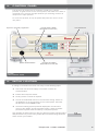
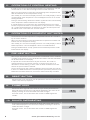
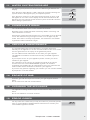
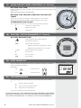
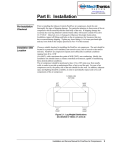
Johnson & Starley
Publication No. ZZ 1184-6 October 2008
Product Identification No: 87B 074
COMBI
SERIES
High Efficiency
Combination
Boilers
USERS INSTRUCTIONS
Natural Gas G20:
Reno HE30C - GC No: 47-416-01
Reno HE37C - GC No: 47-416-02
Propane G31 Variants:
Reno HE30CP - GC No: 47-416-04
Reno HE37CP - GC No: 47-416-03
The Johnson & Starley Reno range has an
energy rating A on a scale of A to G.
For more information see
www.boilers.org.uk
This is a certification mark.
BS EN ISO 9001 : 2000
www.energysavingtrust.org.uk
RELIABILITY YOU CAN TRUST
www.johnsonandstarley.co.uk
COMBI SERIES
High Efficiency Combination Boilers
THE BENCHMARK SCHEME
In order to comply with Building Regulations Part L (Part J in Scotland) the boiler
MUST be fitted in accordance with the manufacturer’s instructions.
Benchmark places responsibilities on both manufacturers and installers. The
purpose is to ensure that customers are provided with the correct equipment for
their needs, that it is installed, commissioned and serviced in accordance with the
manufacturer’s instructions by competent persons and that it meets the requirements
of the appropriate Building Regulations. The Benchmark Checklist can be used to
demonstrate compliance with Building Regulations and should be provided to the
customer for future reference.
Installers are required to carry out installation, commissioning and servicing work in
accordance with the Benchmark Code of Practice which is available from the Heating
and Hotwater Industry Council who manage and promote the Scheme.
Visit www.centralheating.co.uk for more information.
2
www.johnsonandstarley.co.uk
CONTENTS
Benchmark Scheme
2
1.
General Information
4
2.
Symbols on the User Panel
4
3.
Control Panel
5
4.
Initial Lighting
5
5.
Operation of Central Heating
6
6.
Operation of Domestic Hot Water
6
7.
Pre-Heat Button
6
8.
Reset Button
6
9.
Flame loss
6
10.
Boiler Over Heating
6
11.
Water System Pressure
7
12.
Condensing Drain
7
13.
Servicing & Maintenance
7
14.
Escape of Gas
7
15.
Cleaning the appliance
7
16.
Error Codes
7
17.
Analogue Time Control
8
18.
Digital Programmer (if fitted)
8
19.
LCD Display
8
20.
Programmes
8
21.
Selecting AM - PM or 24 Hour Clock
9
22.
Setting the Time
9
23.
Day Key Selection
9
24.
Manual GMT/BST Time Change Over
10
25.
Programming 24 Hour or 7 Day Schedule
10
26.
Event Review
10
27.
Manual Override
10
28.
Continuous Operation
11
29.
Changing an Event
11
30.
Troubleshooting
11
Telephone: 01604 762881
3
1.
GENERAL INFORMATION
Part of the installation and commissioning of this appliance is related to
instructions for use by the heating engineer to the user where specific
requirements may occur, see note below.
This appliance is not intended for use by persons (including children)
with reduced physical, sensory or mental capabilities, or lack of
experience and knowledge, unless they have been given supervision or
instruction concerning use of the appliance by a person responsible for
their safety.
2.
SYMBOLS ON THE USER PANEL
Temperature of central heating flow.
82˚C
Pre-Heat selected.
Pump is running.
Fan is running.
Anti-Cycle feature is in operation.
Outside temperature, when an OTC sensor is connected.
Pressure in heating circuit
Temperature of the domestic hot water.
Summer mode
Ignitor is sparking
Flame modulation.
Opentherm boiler management system is connected.
Error code.
4
www.johnsonandstarley.co.uk
12˚C
1.0 bar
65˚C
3.
CONTROL PANEL
The flip door at the bottom of the boiler is held in the closed
position. To gain access to the control panel, take hold of the side of
the panel at the corners and pull towards you, allowing the door to
drop into the open position.
To close the flip door, lift up the panel and push shut until it clicks
into place.
Space for optional programmer
Power ON/OFF Switch
Central Heating Water
Temperature Control (P1)
Domestic Hot Water
Temperature Control (P2)
Pre-Heat Button
Reset Button
FIGURE 1
USER CONTROL PANEL
4.
INITIAL LIGHTING
If turning on the boiler for the first time carry out the following steps:
Check that the electrical supply to the boiler is ON at the
external isolator.
Ensure all hot taps are closed.
Set any remote controls as required.
Turn the CH and DHW controls to the minimum setting. Switch on
the appliance at the on/off switch on the control panel. The boiler
will then be in the STANDBY mode.
Check the heating system pressure displayed in the RH lower
corner of the display. This should read at least 1.0 bar. A sealed
pressurised system must be filled by a competent person.
Only operate the boiler when you are sure that the system has been filled
and pressurised. If you are in any doubt about the boiler being filled with
water contact your installer.
Telephone: 01604 762881
1.0 bar
5
5.
OPERATION OF CENTRAL HEATING
In order to turn on the central heating and adjust the temperature, turn the
control knob P1 to the desired setting between off and max 82°C.
When the control knob is turned the central heating water temperature will
flash and indicate the new temperature setting.
After a delay of 5 seconds the display will revert to a steady display of actual
central heating water temperature. This will disappear if there is no central
heating demand.
82˚C
82˚C
During a central heating demand the radiator symbol and the central heating
water temperature will be illuminated on the display.
If central heating is not required for any extended period turn the control
knob P1 fully anti-clockwise to the off position. In this position the “heating
off “ symbol will be displayed, the domestic hot water and frost protection
will still be active. This is also the “summer mode”.
6.
OPERATION OF DOMESTIC HOT WATER
The domestic hot water temperature is adjustable between 30°C and 65°C
by the control knob P2.
When the control knob is turned the DHW water temperature will flash and
indicate the new temperature setting.
After a delay of 5 seconds the display will revert to a steady display of actual
DHW temperature. This will disappear if there is no DHW demand.
65˚C
65˚C
During a DHW demand, the tap symbol and the DHW temperature will be
illuminated on the display.
7.
PRE-HEAT BUTTON
With the pre-heat button selected the boiler is maintained in a hot condition
to enable a fast response to any DHW demand. When selected, PRE-HEAT
will be illuminated on the display.
If required this can be selected for all year round use, but will be of
maximum benefit in the summer months, or when there is little or no
demand for central heating, in which case the boiler would become cold
without the pre-heat button selected.
The pre-heat function has a built-in intelligent function that will turn itself off
if there is no DHW demand for a 24 hour period. If previously selected, once
DHW water has been drawn off, the function will automatically re-enable.
8.
RESET BUTTON
Should a fault occur this button can be pressed to reset the controls and
initiate a new start up sequence.
9.
FL AME LOSS
Should the flame signal be lost 5 times in any 4 minute period then the
boiler will lockout and an error code will be displayed in the centre of the
display. Pressing the reset will enable the boiler to relight.
ER:26
If the fault recurs, turn off the boiler and consult a CORGI registered
installer.
10. BOILER OVERHEATING
In the event of the boiler overheating the boiler will lockout and an error
code will be displayed in the centre of the display. Pressing the reset will
enable the boiler to relight.
If the fault recurs, turn off the boiler and consult a CORGI registered
installer.
6
www.johnsonandstarley.co.uk
ER:03
11. WATER SYSTEM PRESSURE
The water system pressure is shown in the bottom right hand of the
display.
If the pressure drops below 1.0 bar it will begin to flash indicating the
system needs to be topped up by a competent person.
If the pressure continues to drop and reaches 0.6 bar, an error code
will appear in the centre of the display and all heat demands will be
blocked. This may indicate a leak and the system should be checked
before being re-pressurised.
1.0
0 bar
0.9bar
ER:37
12. CONDENSATE DRAIN
The condensate drain must not be modified or blocked.
Blockage of the condensate drain caused by debris or freezing, can
cause the boiler to lockout.
If freezing is suspected and the pipe run is accessible, then an attempt
to free the obstruction by pouring hot water on to the pipe may be
made. If this fails to remedy the problem, the assistance of a CORGI
registered installer should be sought.
13. SERVICE & MAINTENANCE
It is recommended that a full maintenance check be carried out
annually on the appliance. It is also recommended to take out a further
service agreement on the expiry of the guarantee period.
You can obtain further information on this from your gas supplier.
The appliance should be checked /serviced by a CORGI registered
installer.
If you require service on your appliance please contact your local
installer or gas supplier.
On completion of the service the installer should fill in the service
section at the rear of the BENCHMARK log book. All installers
registered with CORGI carry an identification card. This card will have
an ID number which should be recorded in your logbook.
If you have any queries regarding your installer you can contact CORGI
by telephone on 01256 372400.
14. ESCAPE OF GAS
Should a gas leak be suspected contact your gas supplier without
delay.
Do not search for leak with a naked flame.
15. CLEANING THE APPLIANCE
The appliance casing should only be cleaned with a damp cloth then
dried.
Do not use abrasive or solvent cleaners.
16. ERROR CODES
For any other error codes that you may encounter on your boiler, please
refer to your Installation & Maintenance Instructions or contact your
local CORGI registered installer.
Telephone: 01604 762881
ER:??
7
17. ANALOGUE TIME CONTROL (if fitted)
SETTING THE TIME
Indicator Arrow
Rotate the dial clockwise, by hand, until the indicator arrow is pointing to the
current time.
I
Note: The time is set in 24 hour format.
SETTING THE CENTRAL HEATING ON AND OFF
TIMES
Select the on times by pushing the black tappets to the outside.
Select the off times by pushing the black tappets to the inside
OVERRIDING THE CLOCK
The clock has a manual on off switch which operates as follows
I
Heating on continuously
Heating on timed
0
Heating off
Black Tappets
18. DIGITAL PROGRAMMER (if fitted)
BUTTON DESCRIPTION
Time/Automatic Run mode selection
Prog
Programme selection
Res
Reset clears all settings
ON/OFF selection in Programme mode
Manual override selector in run mode
+/-1h
Summer/Winter time settings
h
Set the hour
m
Set the minute
Day
Set the days
19. LCD DISPL AY
The LCD display incorporates a number of different elements to display
various data and information
Run Mode:
Off
Continuous Off
On
Days of the week
Time of day
1234567
+1h
AM
88:88
Continuous On
Manual Override On
20. PROGRAMMES
The Digital Programmer will accept up to 20 events. Each event consists
of:
An ON or OFF command
Time of day (hour and minutes)
Single day or multiple days
An event is required for each ON and OFF.
NOTE: MULTIPLE ON OR OFF EVENTS MAY BE PROGRAMMED, SEE EXAMPLE.
BEFORE PROCEEDING WITH SETTING THE TIME AND PROGRAMMING THE
UNIT, PRESS THE RESET KEY TO CLEAR ALL DATA FROM THE MEMORY.
8
www.johnsonandstarley.co.uk
21.
SELECTING AM - PM OR 24 HOUR CLOCK
After pressing reset the display may show AM, numbered days will be
flashing on and off.
If the display does not show AM. It is in 24 hour mode, press and hold the
h key and press the +/-1h key once. AM will appear in the display
If display is in AM/PM mode and 24 hour time mode is desired, press and
hold the h key, press the +/- key once
22.
SETTING THE TIME
If the h and m keys are held down longer than 2 seconds, the numbers
will advance rapidly.
Press and hold the
Time of day
key during the following:
1234567
(If British summer time is in effect, press +/- 1h first)
Press h to advance the current hour (While holding down the
key)
Press m to advance to the current minute (While holding down the
key)
+1h
AM
88:88
Press DAY repeatedly to advance to current day (While holding down the
key)
23.
DAY KEY SELECTION
PRESS ANY KEY
DISPLAY SHOWS
DAYS
0 times
1234567
Every Day
1 times
123456
Mon - Sat
2 times
12345
Mon - Fri
3 times
4 times
5 times
6 times
7 times
8 times
9 times
10 times
67
1
Sat & Sun
Monday
2
Tuesday
3
Wednesday
4
Thursday
5
Friday
6
Saturday
7
Sunday
NOTE: If the days are flashing, it indicates the day of the week was not set
when setting the time. The timer cannot be programmed unless the
day of the week is entered.
Telephone: 01604 762881
9
24.
MANUAL GMT/BST TIME CHANGE OVER
Each year, in the spring press +/- 1 hour to advance the time an hour. In
the Autumn press +/- 1 hour to set back an hour
25. PROGRAMMING 24 HOUR OR 7 DAY SCHEDULE
It may be helpful to write out the programme schedules before beginning.
EXAMPLE:Event 1: On at 7.00am Monday through to Saturday
Event 2: Off at 5.00pm Monday through to Friday
Event 3: Off at 7.00pm Saturday
Three events need to be entered
1234567
EVENT 1
(ON AT 7:00am MONDAY THROUGH SATURDAY)
Press
key once. ON symbol
appears
Press h key to 07am
Press m key once to 00
Press Day key once 123456 is displayed
Press Programme key to enter
EVENT 2
(OFF AT 5.00pm MONDAY THROUGH TO FRIDAY)
Press
key twice. Off symbol
appears
Press h key to 05pm
Press m key once to 00
Press Day key twice 12345 is displayed
Press Programme key to enter
EVENT 3
(OFF AT 7.00pm SATURDAY)
Press
key twice. ON symbol
appears
Press h key to 07pm
Press m key once to 00
Press Day key 9 times 6 is displayed
Press Programme key to enter
Press
key to enter run mode
IF 24 HOUR TIME CONTROL (SAME SCHEDULE EVERY DAY OF THE
WEEK) IS DESIRED IGNORE Day KEY.
2
6.
EVENT REVIEW
To review the programs at any time, press Programme key. Events
will appear in the order they were entered with repeated presses of the
Programme key. After all events have been reviewed the display will go blank
in order to allow you to enter another event. Another press of the Programme
key will display the number of free events spaces.
27. MANUAL OVERRIDE
While in the run mode, pressing the
i.e on to off or off to on.
10
key will reverse the current mode
www.johnsonandstarley.co.uk
AM
--:--
28. CONTINUOUS OPERATION
While in the run mode, press the
permanently on. The
key twice to turn the output to
symbol appears in the display.
To revert back to timed operation press the
appears in the display.
until the
symbol
29. CHANGING AN EVENT
Select the event to be changed with the Programme key. A new set of days
may be selected with Day key just as in initial programming.
Hours and minutes can be changed with the h and m keys
Press the Programme key to store the new programme.
30. TROUBLESHOOTING
Problem: Days are flashing and pressing any key does nothing BUT
key turns output ON and OFF.
Solution: Time of Day and DAY of Week have not been set. This may
occur if the power has been off to boiler for longer than 3 days.
Problem: Time of day was set while holding the
days are still flashing.
key down but the
Solution: Current day of the week has not been set.
Problem: It is 10am and an ON event for 8am was entered but the
output symbol is not ON. Display shows the
and the
symbols.
Solution: After programming the timer does not look back and will not
take place until the event recurs at 8am tomorrow. In order
to turn the boiler ON use the manual override.
Telephone: 01604 762881
11
Company Details
Website Address
Email
www.johnsonandstarley.co.uk
[email protected]
[email protected]
Telephone Number
Fax Number
01604 762881 (Main switchboard)
01604 767408
RENOXTRA
HI-SPEC WARM AIR HEATERS
HOME COMFORT SOLUTIONS
ECONOMAIRE WARM AIR HEATERS
Johnson & Starley are the leading UK &
European manufacturers of a complete range
of Domestic Warm Air Heaters.
All the heaters suit both Replacement and
Upgrade needs and are compliant with the
new (2006) amendments to Part L of the
Building Regulations.
RENO BOILER
RANGE
Johnson & Starley
01604 707012
01604 762884
Sales
Telephone
Fax
01604 707012
01604 764879
HEAT RECOVERY
Telephone
Fax
HOME ‘N’ DRY
VENTILATION
Spares
Service
Telephone
Fax
01604 707011
01604 707017
01604 707026
01604 707017
COMMERCIAL & INDUSTRIAL
H&V SOLUTIONS
CENTRAL EXTRACT
VENTILATION SYSTEM
Telephone
Fax
DRYFLOW
Warm Air Upgrade Enquiry Service
Company Details
Website Address
Email
Dravo Division Industrial H&V
www.dravo.co.uk
[email protected]
T elephone Number
01604 707022
Fax Number
01604 706467
Rhosili Road, Brackmills, Northampton NN4 7LZ
In the interest of continuous development Johnson & Starley Ltd reserve the right to change specifications without prior notice
DRAVO
Johnson & Starley