1
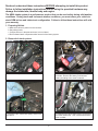
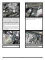
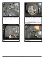
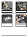
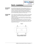
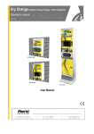
Equipped with AEM® Dryflow™ Filter
No Oil Required!
INSTALLATION INSTRUCTIONS
2006-2011
AEM Induction Systems
PART NUMBER:
21-685C
(Gun Metal Grey Finish)
21-685P (Vacuum Metalized Chrome - VMC)
HONDA
Civic SI
L4-2.0L C.A.R.B. E.O. # D-670-21
1 (800) 992-3000
WWW: http://www.aemintakes.com
PARTS LIST
Description
Qty. Part Number
A
Air Filter Assy. 3.00 X 5” Dry Ele.
1
21-203DK
B
Upper Pipe
1
2-419C/AP
C
Lower Pipe
1
2-1405C/AP
D
Elbow, 2.75/3.00 X 90 Off Set
1
5-281
E
Hose, Adapter 3.00 Flow St/ Ven.
1
5-304
F
Hose, Radiator
1
5-585
G
Hose; 5/8”ID X 18”L
1
5-7018
H
Hose; 5/16ID X 12”L
1
5-2012
I
Hose; 1/2”ID X 11”L
1
5-5011
J
Mount, Rubber 5/8” X 6mm
1
1228598
K
Helical Bundling Wrap; 1/2” X 4”L
1
8-8004
L
Bracket
1
32-3058
M
Bolt, Hex/Flange M6-1.0 X 12
1
1-2110
N
Washer, 6mm Soft Mount
1
08160
O
Nut, M6 Hex Serrated
1
444.460.04
P
1/2” Bnd. Hose Clamp,2.90”-3.75”
1
9452
Q
1/2” Bnd. Hose Clamp,2.31-3.25”
1
9444
R
1/2” Bnd. Hose Clamp,2.56”-3.50”
3
9448
S
Hose Clamp, 1 1/16” Narrow
4
08411
T
Hose Clamp, 3/4”
2
4093-5
Q
D
F
G
M
S
H
R
L
B
R
E
K
C
J
T
N
A
P
O
2
I
Read and understand these instructions BEFORE attempting to install this product.
Failure to follow installation instructions and not using the provided hardware may
damage the intake tube, throttle body and engine.
The AEM® intake system is a performance product that can be used safely during mild weather
conditions. During harsh and inclement weather conditions, you must return your vehicle to
stock OEM air box and intake tract configuration. Failure to follow these instructions will void
your warranty.
1. Preparing Vehicle
a.Make sure vehicle is parked on level surface.
b.Set parking brake.
c.If engine has run in the past two hours, let it cool down.
d.Do not discard stock components after removal of the factory system.
2. Removal of stock system
a. Stock air box system installed.
b. Disconnect the negative and positive battery
terminals. Remove the battery tie down and
battery according to the owner’s manual.
c. Disconnect the mass airflow (MAF) sensor from
the vehicle.
d. Disconnect the two breather hoses connected to
the rubber intake tube. One is a hard line and the
other is rubber.
3
e. Loosen the two hose clamps securing the rubber inlet tube to the stock air box and the throttle
body. Remove the rubber inlet tube from the
vehicle.
f. Remove the MAF sensor from the air box.
Unclip the upper air box from the lower air box.
g. Remove the upper air box and air filter from the
lower air box. Remove the two bolts and one nut
securing the lower air box to the vehicle.
h. Disconnect the lower rubber inlet tube connecting the lower air box to the plastic inlet tube routed
through the bottom of the vehicle.
i. Stock air box system removed from the vehicle.
4
j. NOTE: Ensure the engine is completely cool
before removing the coolant hose, or hot coolant will escape from the cooling system and
cause injury or damage. To do this, the radiator coolant must first be drained. Follow the
procedure described in your vehicle’s factory
service manual to drain the coolant. Be sure to
capture the coolant in an clean container so it
can be recycled back into the system in a later
step.
Using pliers remove the clamp securing the upper
radiator hose to the engine. Also, remove the
smaller breather hose (seen in the upper left hand
side of the image).
k. Using pliers remove the clamp securing the upper radiator hose to radiator. Remove the upper
radiator hose from the vehicle.
l. Disconnect the coolant line connected to the
throttle body.
m. Disconnect the breather hose from the valve
cover and disconnect the small coolant line
connecting the engine to the hard lines.
5
n. Remove the lower inlet tube and the bracket
securing the positive battery cable. The bracket
securing the positive battery cable has two bolts
that will need to be removed.
o. Raise the front of the vehicle with a jack. Refer
to your owner’s manual for proper jack and jack
stand placement to properly support vehicle. Support your vehicle using properly rated jack stands
before wheel removal or while working under the
vehicle. NEVER WORK UNDER A VEHICLE
WITHOUT USING JACK STANDS. Remove the
driver side wheel.
p. Remove the fender liner on the driver side
wheel.
q. Remove the bolt securing the resonator to the
inner fender well.
6
r. Remove the second bolt securing the lower
resonator in place; it is located near the front of the
vehicle.
s. Stock air box system removed from the vehicle.
3. Installation of AEM® intake system.
a.When installing the intake system, do not completely tighten the hose clamps or mounting hardware until instructed
to do so.
b. Carefully install the MAF sensor into the upper
intake pipe using the two stock bolts.
c. Align the airflow straightener/coupler with the
MAF sensor and insert into the upper intake pipe.
Ensure the airflow straightener/coupler is properly
oriented as shown. Slide two #48 hose clamps
onto the coupler as shown, but do not completely
tighten.
7
d. Install the supplied 5/16” hose to the throttle
body inlet and the engine inlet as shown.
Secure each end of the hose with the provided
hose clamps.
e. Install the supplied radiator hose using the stock
hose clamps.
f. Route the radiator hose as shown. Trim the battery tray for clearance if necessary.
g. Install the two supplied breather hoses, one to
the valve cover and the other to the small plastic
valve located on the engine. Secure each hose
with the supplied hose clamps.
h. Install the elbow coupler onto the throttle body,
ensuring it does not contact any of the surrounding
parts. Loosely secure it with the supplied #9444
hose clamp.
8
i. Install the intake assembly assembled in step 3c into the elbow. Connect the MAF sensor to the MAF sensor harness
connector. Ensure the intake pipe is completely seated into the elbow and is properly positioned so it does not obstruct
the shift linkage. Put the vehicle in third gear to ensure that the intake pipe will clear the shift linkage. Connect the two
breather hoses installed in step 3g to the upper intake pipe and secure with the supplied hose clamps.
NOTE: This installation step is critical, please take your time and make sure that the upper intake pipe is NOT
interfering with the vehicle’s shift linkage.
j. Install bracket #32-3058 onto the upper intake
pipe’s bracket with the supplied bolt #1-2110.
Attach the blue harness to the metal clip.
k. Screw the rubber mount into the threaded hole
of vehicle’s frame.
l. Route the lower intake pipe into the engine bay
and attach the upper end to the upper intakes
pipe’s coupler.
m. Install the supplied helical wrap onto the clutch
line where the lower intake pipe passes.
9
n. Loosely secure the lower intake pipe’s bracket
to the rubber mount installed in step 3k. Secure
the bracket with the supplied washer and serrated
nut.
o. Install the air filter onto the lower end of the
lower intake pipe. Once proper fitment is achieved
secure the air filter to the intake pipe with a #9452
hose clamp.
p. Install the fender liner and any hardware that
was removed in step 2p. Trim the fender liner to
allow clearance for the lower intake pipe.
NOTE: Failure to install the fender liner will
result in diminished performance and increase
the potential for engine damage due to water
ingestion in rainy conditions.
10
Factory air box system installed
AEM® intake system installed
4. Reassemble Vehicle
a.
Be sure to replenish the coolant that was drained during step 2j. Be sure to purge the coolant system
before driving the vehicle. For any additional details regarding this procedure refer to the factory service
manual.
b. Position the inlet pipes for the best fitment. Be sure that the pipes or any other components do not contact any part
of the vehicle. Tighten the rubber mount, all bolts, and hose clamps.
c.With the engine turned off, have a friend run the shift lever through the 6 gears, and ensure that the counter weight
for the shift rod does not contact the intake pipe. If the shifter rod makes contact with the pipe, DO NOT drive the
vehicle until this has been corrected by re-adjusting the pipe so it does not make contact.
d.
Wheel: Install the driver side wheel using the factory torque specification (see owner’s manual).
e.Check for proper hood clearance. Re-adjust pipes if necessary and re-tighten them.
f. Install the battery and battery tie down according to the owners manual. Reconnect the positive battery terminal.
g.Inspect the engine bay for any loose tools and check that all fasteners that were moved or removed are properly
tightened.
h.Reconnect negative battery terminal and start engine. Let the vehicle idle for 3 minutes. Perform a final inspection
before driving the vehicle.
5. CARB Sticker Placement
a.The C.A.R.B. exemption sticker, (attached), must be visible under the hood so that an emissions inspector can see
it when the vehicle is required to be tested for emissions. California requires testing every two years, other states
may vary.
6. Service and Maintenance
a.AEM Induction Systems requires cleaning the intake system’s air filter element every 100,000 miles. When used in
dusty or off-road environments, our filters will require cleaning more often. We recommend that you visually inspect
your filter once every 25,000 miles to determine if the screen is still visible. When the screen is no longer visible
some place on the filter element, it is time to clean it. To clean, purchase our Synthetic air filter cleaner, part number
99-0624 and follow the easy instructions.
b.Use window cleaner to clean your powder coated AEM® intake tube.
NOTE: DO NOT USE aluminum polish on powder coated AEM® intake tubes.
For technical inquiries
e-mail us at
[email protected]
or
call us at
800.992.3000
11
AEM Air Intake System Warranty Policy
AEM® warrants that its intake systems will last for the life of your vehicle. AEM will not honor this warranty due to mechanical damage (i.e. improper installation or fitment), damage from misuse, accidents or flying debris. AEM will not warrant
its powder coating if the finish has been cleaned with a hydrocarbon-based solvent. The powder coating should only be
cleaned with a mild soap and water solution. Proof of purchase of both the vehicle and AEM intake system is required for
redemption of a warranty claim.
This warranty is limited to the repair or replacement of the AEM part. In no event shall this warranty exceed the original
purchase price of the AEM part nor shall AEM be responsible for special, incidental or consequential damages or cost
incurred due to the failure of this product. Warranty claims to AEM must be transportation prepaid and accompanied with
dated proof of purchase. This warranty applies only to the original purchaser of product and is nontransferable. Improper
use or installation, use for racing, accident, abuse, unauthorized repairs or alterations voids this warranty. AEM disclaims
any liability for consequential damages due to breach of any written or implied warranty on all products manufactured by
AEM. Warranty returns will only be accepted by AEM when accompanied by a valid Return Merchandise Authorization
(RMA) number. Credit for defective products will be issued pending inspection. Product must be received by AEM within
30 days of the date RMA is issued.
If you have a warranty issue, please call (800) 992-3000 and our customer service department will assist you. A proof of
purchase is required for all AEM warranty claims.
12
10-321F
04/06/15