1
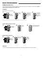
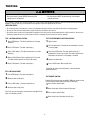
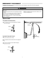
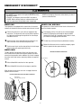
MEDIUM DUTY LOGIC
USER'S GUIDE
MT5011UCHB
MH5011URCHB
MH5011ULCHB
MJ5011UCHB
CONTACT INFORMATION
Radio Receiver
Built on Board
Installation Date
www.Raynor.com
315 MHz
INTRODUCTION
Congratulations on purchasing a quality, Raynor Medium Duty Commercial Door Operator. Your new operator is capable of operating
up to 12 cycles per hour or 50 cycles per day. It is equipped with a built in radio receiver that is compatible with our existing 315 MHz
product line as well as a Timer-to-Close (TTC) feature that can be enabled when LiftMaster Commercial Protector System® is installed
and aligned properly.
BASIC PROGRAMMING
DETERMINE THE WIRING TYPE
The functionality of this operator is based on the wiring type. The operator is shipped from the factory in standard C2 wiring type
(factory default). LIFTMASTER MONITORED ENTRAPMENT PROTECTION (LMEP) DEVICE IS REQUIRED.
NOTES:
• The LED on the logic board will blink once when in C2 and twice when in B2.
• The operator will automatically convert to B2 wiring when Monitored Entrapment Protection Device is installed. If the Monitored
Entrapment Protection Device is removed, the operator will go into a Restricted Close mode**. Turn power OFF and ON to reset wiring
type.
** Restricted close mode requires a constant pressure close command. The operator will begin closing after a 5 second delay and will
continue to close to the close limit switch. The operator will stop if the pressure to close is released before reaching the close limit.
RECOMMENDED INSTALLATION: B2 WIRING TYPE WITH
MONITORED ENTRAPMENT PROTECTION DEVICE
• Momentary contact to open, close and stop.
• Open override that reverses when closing by any opening
device.
• Wiring for entrapment protection device to reverse.
NOTE: The operator will automatically convert to B2 wiring
when Monitored Entrapment Protection Device is installed. (See
accessories page for Monitored Entrapment Protection Devices.)
• Timer-to-Close (TTC) feature available.
No Programming Required
MONITORED ENTRAPMENT PROTECTION DEVICE
Photoelectric Sensor
2
BASIC PROGRAMMING
DETERMINE THE WIRING TYPE
ALTERNATE INSTALLATION: C2 WIRING TYPE WITH MONITORED
ENTRAPMENT PROTECTION DEVICE
ALTERNATE INSTALLATION: C2 WIRING TYPE WITHOUT
MONITORED ENTRAPMENT PROTECTION DEVICE
(FACTORY DEFAULT)
• Momentary contact to open and stop with constant pressure to
close.
• Open override that reverses when closing by any opening
device.
• Wiring for entrapment protection device to reverse.
NOTE: The operator will automatically convert to B2 wiring
when Monitored Entrapment Protection Device is installed. (See
accessories page for Monitored Entrapment Protection Devices.)
• Timer-to-Close (TTC) feature not available.
• Momentary contact to open and stop with constant pressure to
close.
• Open override that reverses when closing by any opening
device.
• Wiring for entrapment protection device to reverse.
NOTE: The operator will automatically convert to B2 wiring
when Monitored Entrapment Protection Device is installed.
(See accessories page for Monitored Entrapment Protection
Devices.)
• Timer-to-Close (TTC) feature not available.
NON-MONITORED ENTRAPMENT PROTECTION DEVICE
MONITORED ENTRAPMENT PROTECTION DEVICE
Sensing Edge
Photoelectric Sensor
Reset to FACTORY DEFAULT (C2) without Monitored Entrapment
Protection Device:
To Program:
Press and hold the LEARN and CLOSE buttons until the LED
goes out (approximately 3 seconds).
1
Electrical Box
1 Remove any monitored entrapment protection devices.
Logic Board
and hold the LEARN and STOP buttons until LED goes
2 Press
out (approximately 3 seconds).
D7
U4 D6
014A1030
C20
D5
D4
J4
C32
R25
C31
TP1
C9
U1
C21
LEARN
L5
^^^^
AUX
AUX ANT
ANT
C18
R27
J2
STOP
CLOSE OPEN
D14
TTC
LEARN STOP CLOSE OPEN
LED
D9
1
2
3
4
5
6
7
LMEP1
LMEP2
COM
INTRLK
STOP
CLOSE
OPEN
K2
LT
C29
R24
P1
D14
LED
1
2
3
4
5
6
7
To Reset to B2 with Monitored Entrapment Protection Device:
1
Press and hold the LEARN and STOP buttons until the LED
goes out (approximately 3 seconds).
3
BASIC PROGRAMMING
WARNING
To prevent possible SEVERE INJURY or DEATH:
• Install a LiftMaster Monitored Entrapment Protection (LMEP)
device.
• NEVER permit children to operate or play with door control
push buttons or remote controls.
• Activate door ONLY when it can be seen clearly, is properly
CAUTION
adjusted and there are no obstructions to door travel.
• ALWAYS keep door in sight until completely closed. NEVER
permit anyone to cross the path of closing door.
RADIO OPERATION
MODE
OPEN
CLOSE
STOP
REVERSE WHILE
CLOSING
B2
X
X
X
X
B2 with TTC
X
X (3-button remote)
X
X
C2
X
X
X
TTC RESET
X when open
AVERTISSEMENT
AVE
REMOTE CONTROLS
ATTENTION
Built in 315 MHz radio receiver permits as many as 20 Security✚® remote controls or dip switch remote controls in any combination.
AV
SINGLE BUTTON REMOTE CONTROL
TTC
1
R27
1
D14
LED
2
1
3
3
LEARN
4
5
STOP
6
7
CLOSE OPEN
LEARN
2
D14
LED
LMEP1 LMEP2 COM INTRLK STOP CLOSE OPEN
^^^^
TTC
LMEP1 LMEP2 COM INTRLK STOP CLOSE OPEN
ANT
AUX ANT
AUX
AUX ANT
Press and release
the LEARN button
(LED will light).
and hold the button on the remote control until the LED
2 Press
flashes rapidly, then release to complete programming (LED
will go out).
4
STOP
5
CLOSE OPEN
6
7
Repeat steps 1 and 2 for additional remote controls.
3-BUTTON REMOTE CONTROL TO OPERATE AS A WIRELESS 3-BUTTON CONTROL STATION
NOTE: The feature will use 3 of the 20 memory channels in the operator.
ADVERTENCIA
2
D14
LED
5
STOP
6
CLOSE OPEN
7
LEARN
3
4
LEARN
3
3
LEARN
4
4
STOP
STOP
7
7
CLOSE OPEN
6
6
CLOSE OPEN
PRECAUCIÓN
5
5
Press the desired
button on the logic
board (OPEN,
CLOSE or STOP).
Release both
buttons.
R27
1
2
D14
LED
2
D14
LED
LMEP1 LMEP2 COM INTRLK STOP CLOSE OPEN
R27
1
1
LMEP1 LMEP2 COM INTRLK STOP CLOSE OPEN
^^^^
TTC
LMEP1 LMEP2 COM INTRLK STOP CLOSE OPEN
ANT
AUX ANT
AUX
AUX ANT
Press and hold
the LEARN button
(LED will light).
TTC
2
TTC
1
Repeat steps 1 through 3 to program additional buttons.
TO ERASE ALL REMOTE CONTROLS
TTC
1
R27
1
2
D14
LED
1
3
3
LEARN
4
5
STOP
6
7
CLOSE OPEN
LEARN
2
D14
LED
LMEP1 LMEP2 COM INTRLK STOP CLOSE OPEN
^^^^
TTC
4
STOP
5
7
CLOSE OPEN
6
LMEP1 LMEP2 COM INTRLK STOP CLOSE OPEN
ANT
AUX ANT
AUX
AUX ANT
Press and hold the
LEARN button (over
5 seconds) until the
LED goes out. All
programmed remote
controls will be
erased.
4
and hold the desired button of the remote
3 Press
control until LED flashes rapidly, then release.
AD
A
BASIC PROGRAMMING
TIMER-TO-CLOSE (TTC)
Timer-to-Close feature enables the operator to close from the open limit after a preset time, adjustable from 5 to 60 seconds. Requires
LiftMaster Monitored Entrapment Protection (LMEP) device.
TO PROGRAM
Begin with door in fully closed position.
1
2
4
R27
1
2
4
4
4
5
Press and release
the TTC button to
exit programming
mode. The LED
will flash once per
5 seconds of timer
setting.
7
CLOSE OPEN
6
7
7
CLOSE OPEN
6
6
7
CLOSE OPEN
6
CLOSE OPEN
STOP
STOP
5
5
STOP
5
STOP
LEARN
3
4
LEARN
3
D14
LED
2
D14
LED
7
LEARN
3
6
CLOSE OPEN
LMEP1 LMEP2 COM INTRLK STOP CLOSE OPEN
R27
1
D14
LED
2
5
STOP
LEARN
4
LMEP1 LMEP2 COM INTRLK STOP CLOSE OPEN
R27
1
D14
LED
3
3
LEARN
LMEP1 LMEP2 COM INTRLK STOP CLOSE OPEN
R27
2
2
D14
LED
Every press and release
of the STOP button
will add 5 seconds to
the Timer-to-Close.
Example: 30 second
TTC = 6 presses of the
STOP button.
TTC
TTC
TTC
TTC
1
1
LMEP1 LMEP2 COM INTRLK STOP CLOSE OPEN
^^^^
TTC
LMEP1 LMEP2 COM INTRLK STOP CLOSE OPEN
ANT
AUX ANT
AUX
AUX ANT
Press and
release the
LEARN button
(LED will light).
3
Press and
release the
TTC button.
The TTC will become active after completion of the next open cycle. NOTE: The LED does not indicate that timer is running.
TO VERIFY TIMER-TO-CLOSE (TTC) SETTING
TTC
R27
1
Press and release the TTC button a
second time. The LED will flash once
per 5 seconds of timer setting.
2
3
4
4
4
5
STOP
6
7
7
CLOSE OPEN
6
7
CLOSE OPEN
6
CLOSE OPEN
5
STOP
5
STOP
LEARN
3
7
CLOSE OPEN
6
LEARN
D14
LED
2
D14
LED
STOP
5
LEARN
3
4
LMEP1 LMEP2 COM INTRLK STOP CLOSE OPEN
R27
1
D14
LED
2
LEARN
3
LMEP1 LMEP2 COM INTRLK STOP CLOSE OPEN
R27
1
^^^^
TTC
D14
LED
2
LMEP1 LMEP2 COM INTRLK STOP CLOSE OPEN
ANT
AUX ANT
AUX
AUX ANT
1
LMEP1 LMEP2 COM INTRLK STOP CLOSE OPEN
Press and hold
the LEARN button
(LED will light).
3
Press and
release the
TTC button.
TTC
2
TTC
1
CLEAR THE TIMER-TO-CLOSE (TTC)
TTC
3
R27
1
Press and hold
the TTC button
for 6 seconds.
2
D14
LED
2
7
4
4
LEARN
6
CLOSE OPEN
3
5
STOP
LEARN
3
D14
LED
4
LEARN
3
3
LEARN
Release the
TTC button
(LED will go
out). The TTC
will no longer
be active.
5
5
STOP
STOP
4
STOP
5
7
7
CLOSE OPEN
6
6
CLOSE OPEN
7
CLOSE OPEN
6
LMEP1 LMEP2 COM INTRLK STOP CLOSE OPEN
R27
1
2
D14
LED
2
D14
LED
LMEP1 LMEP2 COM INTRLK STOP CLOSE OPEN
R27
1
1
LMEP1 LMEP2 COM INTRLK STOP CLOSE OPEN
^^^^
TTC
LMEP1 LMEP2 COM INTRLK STOP CLOSE OPEN
ANT
AUX ANT
AUX
AUX ANT
Press and
release the
LEARN button
(LED will light).
TTC
2
TTC
1
TIMER DEFEAT
The TTC can be temporarily disabled by pressing a STOP button. TTC will become enabled after the next open command.
5
NG TESTING
WARNING
N
WARNING
To avoid SERIOUS personal INJURY or DEATH:
• Disconnect electric power BEFORE performing ANY
adjustments or maintenance.
Turn on power, LED will flash 4 times on power up. Test all controls and entrapment protection devices to make sure they are working
properly. It may be necessary to refer back to the installation manual for adjustment of the limits.
IMPORTANT NOTES:
• Do not leave power to the operator on unless all entrapment protection devices have been tested and are working properly.
• Be sure you have read and understand all safety instructions included in this manual.
• Be sure the owner or person(s) responsible for operation of the door have read and understand the safety instructions, know how to
electrically operate the door in a safe manner and how to manually disconnect the door from the operator.
EMENT
ON
AVERTISSEMENT
TEST 3-BUTTON CONTROL STATION
TEST THE ENTRAPMENT PROTECTION DEVICES
open
1 Press OPEN button. (The door should move in the AVERTISSEMENT
1 Open the door.
direction.)
2 Press STOP button. (The door should stop.)
an obstruction in the path of the photoelectric sensors
2 Place
or sensing edge.
CLOSE button. (The door should move in the close
3 Press
direction.)
the CLOSE button. The door should not close if
3 Press
photoelectric sensors are installed. The door should close to
obstruction and reverse if sensing edge is installed.
4 Release CLOSE button. Door should stop if in C2 mode.
4 Remove the obstruction.
(The door should continue closing if in B2 mode.)
5 Press STOP button. (The door should stop.)
5 Press CLOSE button. Door should close.
If door did not reverse from obstruction, check entrapment
protection devices.
TEST LIMIT ADJUSTMENT
NCIA1 Press OPEN button. (The door should open.)
ÓN
• ALL maintenance MUST be performed by a trained door
systems technician.
2 Allow the door to fully open.
3 Press CLOSE button. (The door should close.)
ADVERTENCIA
TEST REMOTE CONTROL
Requires B2 wiring type and compatible LiftMaster remote control.
ADVERTENCIA
In C2 wiring the remote control will open the door only.
1 Press remote control button.
4 Allow the door to fully close.
2 Door should open. Allow the door to fully open.
If the limits are not set properly, remove power and adjust limits
(refer to installation manual).
3 Press remote control button.
4 Door should close. Allow door to fully close.
6
EMERGENCY DISCONNECT
The operators have provisions for manually operating the door in case of emergency or power failure. Refer to the appropriate
instructions for your model operator.
WARNING
To prevent possible SERIOUS INJURY or DEATH from a falling
door or arm:
• DO NOT stand under the door arm when pulling the emergency
release.
• If possible, use emergency release handle to disengage trolley
ONLY when door is CLOSED. Weak or broken springs or
unbalanced door could result in an open door falling rapidly
and/or unexpectedly.
W
CAUTION
• NEVER use emergency release handle unless doorway is clear
of persons and obstructions.
MODEL MT/BMT
TO DISCONNECT DOOR FROM OPERATOR
1
Pull emergency release handle straight down. Emergency
disconnect will open.
AVERTISSEMENT
AVE
Emergency
Disconnect
Emergency
Disconnect
ATTENTION
AVE
Door Arm
TO RECONNECT DOOR ARM TO TROLLEY
NOTI
CE
1
Lift free end of door arm to trolley.
2
Pull emergency release handle to allow arm to engage roll
pin.
3
Let go of the emergency release handle. Emergency
disconnect will close.
Door
ADVERTENCIA
Emergency
Disconnect
Emergency
Release Handle
PRECAUCIÓN
Door Arm
7
AD
AD
NG EMERGENCY DISCONNECT
WARNING
N
WARNING
To prevent possible SERIOUS INJURY from a moving chain:
• DISCONNECT electric power to the operator BEFORE manually
operating your door.
• If possible, use emergency disconnect ONLY when door is
CLOSED. Weak or broken springs or unbalanced door could
result in an open door falling rapidly and/or unexpectedly.
• NEVER use emergency disconnect unless doorway is clear of
persons and obstructions.
MODEL MH
MODELS MJ AND MGJ
These operators are equipped with a manual hoist. An electrical
interlock will disable the electrical controls when the hoist is used.
This operator has a floor level disconnect chain to disconnect the
door from the door operator.
the disconnect chain (sash chain) to engageAVERTISSEMENT
the hoist
disengage, pull the chain and secure in the disengaged
1 Pull
EMENT
1 To
mechanism. The disconnect chain may be locked in position
position by slipping the end through the keyhole bracket
by slipping the end through the keyhole of the chain keeper
mounted on the wall.
ON
AVERTISSEMENT
2
Operate the door in the desired direction by pulling on one
side or the other of the continuous loop hoist chain.
3
The disconnect chain must be released from the chain keeper
before the door will operate again electrically.
2
The door may now be pushed up or pulled down manually.
3
Release the disconnect chain or reset the emergency egress
device to operate the door again electrically.
MODEL MHS
EMERGENCY DISCONNECT FOR MODELS MJ
The MHS operator includes both a floor level disconnect sash
chain to disconnect the door from the door operator that allows
manual push up operation and an additional sash chain to engage
the manual chain hoist that also electrically disables the operator
controls.
Keyhole Bracket
1 Refer to Model MH instructions for hoist operation.
2
NCIA
ÓN
mounted on the wall. Or if emergency egress device is used,
pull handle to disengage operator from door.
Refer to Model MJ instructions for emergency operation.
ADVERTENCIA
When the manual chain hoist sash chain is engaged, electrical
operation will not function.
ELECTRICAL INTERLOCK WITH HOIST FOR MODELS MH AND MHS
ADVERTENCIA
Chain Keeper
(with pad locking provisions)
8
TROUBLESHOOTING
To locate a dealer in your area visit us online at www.Raynor.com.
CONDITION
POSSIBLE CAUSE
FIX
OPERATOR WILL NOT
RESPOND TO ANY
No power
COMMANDS
➤ Check circuit breaker.
Accessory failure
➤ Verify photoelectric sensors are aligned.
Possible component failure
➤ Contact your installing dealer.
OPERATOR MAKES
NOISE BUT DOOR
DOES NOT MOVE
Operator requires adjustment
➤ Contact your installing dealer.
DOOR DRIFTS AFTER
OPERATOR STOPS
Operator or door requires
adjustment
➤ Contact your installing dealer.
DOOR OPENS/CLOSES
Operator requires adjustment
TOO FAR
➤ Contact your installing dealer.
DOOR REVERSES
UNEXPECTEDLY
Entrapment protection device
activated
➤ Verify photoelectric sensors are aligned. If photoelectric sensors are
aligned and operator still does not operate properly, contact your
installing dealer.
Remote control is not
programmed
➤ See PROGRAMMING REMOTE CONTROLS section.
RADIO FUNCTIONALITY
NO RESPONSE
Low battery
➤ Replace battery.
REMOTE CANNOT BE
PROGRAMMED
Low battery
➤ Replace battery.
POOR RANGE
Low battery in remote
➤ Replace battery.
Possible radio interference
➤ Contact your installing dealer.
NG MAINTENANCE SCHEDULEWARNING
N
WARNING
To avoid SERIOUS personal INJURY or DEATH from
electrocution, disconnect ALL electric power BEFORE performing
ANY maintenance.
Every 3 months or 5,000 cycles repeat all tests in the Testing section.
Call qualified service contractor for maintenance. To locate a dealer in your area visit us online at www.Raynor.com.
The operator should be serviced at the following intervals:
• Every 3 months or 5,000 cycles
• Every 6 months or 10,000 cycles
• Every 12 months or 20,000 cycles
EMENT
ON
AVERTISSEMENT
AVERTISSEMENT
9
OPERATOR NOTES
10
ACCESSORIES
ENTRAPMENT PROTECTION DEVICES
REMOTE CONTROLS 315 MHZ
®
LiftMaster offers a variety of SECURITY✚
Remote Controls for your application needs.
Single to 4-Button, visor or key chain. Contact
your authorized dealer.
CPS-UN4
Commercial Protector System:
LiftMaster Monitored Entrapment Protection
(LMEP) provides protection on doors up to 40'
wide. NEMA-4 rated.
CPS-U
371LM
1-Button SECURITY✚® Remote Control:
Includes visor clip.
Commercial Protector System:
LiftMaster Monitored Entrapment Protection
(LMEP) provides protection on doors up to
30' wide.
373LM
3-Button SECURITY✚® Remote Control:
Includes visor clip.
OPEN
CLOSE
333LM
CPS-EI
CPS-EI
E1
3-Button Tri-Colored Dip Switch Remote
Control:
Open/Close/Stop functionality. Includes visor
clip.
E2
E3
LMEP2
LMEP1
E4
40-34141-1
65ME1234
WPB1LM3
Wireless Single Push Button Control
SECURITY✚®:
Rugged composite housing. (Wireless controls
cannot be used in place of hard wired controls.)
Miller ME123 4-Wire Monitored Safety Edge:
For sectional or rolling doors.
65ME110
Miller ME110 4-Wire Monitored Safety Edge:
For rolling grilles and counter shutters.
WPB3LM3
Wireless 3 Button Control Station
SECURITY✚®:
Rugged composite housing. (Wireless controls
cannot be used in place of hard wired controls.)
MOUNTING BRACKETS
10-12360
Mounting Brackets:
Angle mounting bracket, Painted steel, for MJ,
MH, and MHS.
WKP5LM3 (5 4-digit entry codes)
WKP250LM3 (250 4-digit entry codes)
Wireless Access Control Keypads
SECURITY✚®:
Rugged composite housing. (Wireless controls
cannot be used in place of hard wired controls.)
1
2
4
3
5
6
7
8
9
*
0
#
10-9095
Medium Duty Angle Mounting Bracket:
Heavy-gauge steel bracket. May be welded.
For use with MJ, MGJ, and MH operators.
CONTROL STATIONS
02-102
OPEN
2-Button Control Station:
Steel enclosure.
CLOSE
CHAIN TENSIONERS
02-103
71-6023
OPEN
3-Button Control Station:
Steel enclosure.
^
OP
EN
CLOSE
^
OPEN
Monitored Sensing Edge Interface:
Requires 4-wire monitored sensing edge.
Chain Tensioner:
For 1" shafts
CLOS
E
O
STOP
02-109
Key Control Station:
Indoor flush mount, NEMA 1.
71-6125
OPEN
CLOSE
Chain Tensioner:
For 1-1/2" shafts
11
For Jackshaft Type
Operators
ACCESSORIES
FIELD MODIFICATION KITS
ANTENNA
71MLSBC
EXT-ANT
Single Button Control:
Provides additional input for Single Button Control functionality.
Input functions as Close input when the operator is stopped at
the Open limit. Input functions as Open input at all other times.
Also used with external radio controls.
71 MLMOTION
Door-In-Motion:
Provides dry contact and a terminal block with contacts
switched to power an auxiliary device while the door is in
motion.
01-35252B
Antenna:
External kit for medium duty.
86LM (15')
86LMT (25')
Antenna Extension Kit:
The antenna extension kit can be used with
EXT-ANT for maximum radio receiver range.
© 2010, The Chamberlain Group, Inc.
All Rights Reserved