1
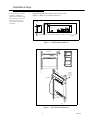
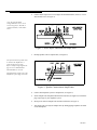
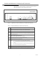
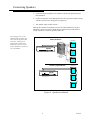
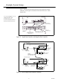
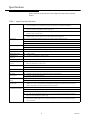
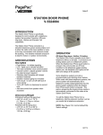
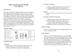
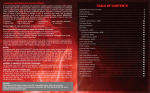
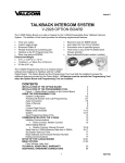
PagePac
®
by
ISSUE 2
PagePac Plus AmpliCenter
V-5328020/V-5328100/V-5328300
Installation and Use
947169
Installation Steps
Note: If installed next to other
equipment, including the
PagePac Plus Controller and
Zone Expansion Units, leave
at least four inches space
above and below for proper
ventilation.
1.
Mount the PagePac® Plus AmpliCenter to either the wall
(Figure 1), cabinet, or a 19 inch rack (Figure 2).
SIDE VIEW
105 - 120 VAC
210 - 240 VAC
50 - 60 Hz
Figure 1. Wall Mounted Hardware
FRONT DETAIL
1.750
TYPICAL
PagePac Plus
R
PagePac Plus
R
Ampli Cen ter D300
AmpliCenter D300
19''
COMBINATION
PAN HEAD
PILOT POINT
# 10 - 32 (TYPICAL)
REAR DETAIL
POWER STRIP
Figure 2. Rack Mounted Hardware
2
947169
2.
Connect music input wires to Left, Right, and Ground terminals, if stereo, or Left
and Ground, if not (see Figure 3).
Note: The optional audio
background music source can be
a CD or tape player, AM, FM, or
commercial radio, or other audio
device.
Figure 3. Music Input Connections on AmpliCenter
3.
Hookup speaker cable to AmpliCenter (see Figure 4).
Note: If more than one speaker cable
is routed to the AmpliCenter, a
connector block is necessary.
Refer to sample wiring diagrams on
page 8. It is recommended that
22GA shielded wire be used.
DO NOT hook up speaker wires with
AmpliCenter power plug connected!
Figure 4. Speaker Connection on AmpliCenter
4.
Connect host telephone system to Amplicenter (see Figure 5).
5.
Set the AmpliCenter Telephone Mode Selection Switch (see Figure 6) to match the
page output type of your telephone system.
6.
Insert power cord into AmpliCenter and into wall outlet (see Figure 7).
7.
Test paging zone served by the AmpliCenter by dialing paging telephone extension
or use microphone.
3
947169
A M P L IC E N T E R
P A G E
M U S IC
IN
D N G
1 C
G NI R
PI T
D
O U T P U T
D
M IC
G
S W IT C H
P A G E
IN P U T
L
With a microphone, hook the mic
switch to C1 and Grd, and the mic
output to Tip and Ring.
M IC
O O
O R
Y R
Y R
Use Tip and Ring if connecting to
a Loop Start or Ground Start
interface port in host telephone
system.
S P
N U
O L
O L
G NI K C U D
T E R M IN A L S
X O V E G A P
L E V E L T U P NI
T F E L
T H GI R
D N U O R G
C 1
IN
PI T
G NI R
L O W F R E Q
C U T -O F F
Use Tip and Ring if installing to an
existing paging system (low
voltage output), VOX activated.
O U T
R E W O P
D A O L R E V O
T U P T U O D E C N A L A B N U
D E S S E C C A E G A P
7 0 V
T O
C O N T R O L L E R
U N IT
D N U O R G
0 d B m
O U T
D N U O R G
1 0 5 - 1 2 0 V A C
2 1 0 - 2 4 0 V A C
5 0 - 6 0 H z
B A C K P A N E L
T R A T
T R A T S D
Z I H P O
S M H O 0 0 6 P O
Note: Connect the 4-wire RJ-11
type plug (used with telephones) to
the Page Input connector (far
right), or use the Page in
terminals.
U S E
o r C O N N E C T O R
P A G E -IN
O P T IO N S
H O S T
T E L E P H O N E
S Y S T E M
T IP A N D R IN G F R O M
L O O P S T A R T O R G R O U N D
S T A R T P O R T
E X IS T IN G P A G IN G A M P L IF IE R ,
L O W V O L T A G E O U T P U T T O
T IP a n d R IN G
Figure 5. Host Telephone System Connection
Figure 6. Telephone Mode Switch Setting
Note: Do not use extension
cords or plug into locally,
“safety-fused” outlets.
P A G E IN
105 - 120 VAC
210 - 2 4 0 VAC
50 - 60 Hz
6 F O O T
P O W E R C A B L E
Figure 7. Power Cable
4
947169
Note: If no page is heard,
refer to the troubleshooting
Guidelines.
8.
Adjust sound levels using AmpliCenter controls, if necessary.
Using a small standard screwdriver, make the following adjustments (see Figure 8).
Figure 8. Test Page Adjustments
1.
Adjust the Low Frequency Cut Off control. This control cuts out the low
frequency bass so that horns and small speakers are not over-driven and
distorted by excessive bass energy. Cut off frequency is continuously adjustable
from 50 Hz (full CCW rotation) to 400 Hz
(full CW rotation).
2.
The Page VOX (voice activation) sensitivity is turned fully counterclockwise if the Dry Loop feature is not used.
3.
Adjust Music Input Level. Clockwise rotation will increase the level. Listen and set
to a comfortable level.
4.
Using a telephone from the host system, dial the paging extension.
Speak into the telephone in a normal manner. Your voice should be
heard from all connected speakers. the AmpliCenter Page input has an automatic
level control (ALC) which keeps loud voices and normal voices output at the same
level. Beware of paging from a telephone directly
under a loudspeaker; feedback howl can occur. (A feedback eliminator will solve
this problem).
5.
Readjust Music input level to the desired loudness relative to Paging loudness.
6.
Some loudspeaker taps may have to be readjusted to get even
coverage at all locations. be sure that the final speaker tap setting
totals do not exceed the power rating of the AmpliCenter.
7.
Adjust Music Ducking level. this feature allows music to continue to be heard
during a Page, but at a reduced level. The range is from less than
40 dB (full CCW) to -6 dB (full CCW). If music-in is not connected, set to
full CCW.
5
947169
Troubleshooting
Some common problems encountered when the paging system is not operating are
described below. Check each item in the order listed.
1.
No AC power to AmpliCenter.
2.
Host telephone system failure.
3.
Host system page port failure.
4.
A hardwire disconnect between host system and PagePac® Plus.
5.
AmpliCenter switch settings tampered with.
If the problem has not been resolved by checking the preceding items, follow the
steps described in Table 1.
Table 1. Troubleshooting Table
Problem
Corrective Action
Page access from telephone system working, but page is
not heard.
No power to AmpliCenter.
Host system not passing call through to AmpliCenter.
Telephone mode selection switch not set correctly for host telephone
system.
Ground start - Tip and Ring reversed or AmpliCenter not grounded.
Audio signal not reaching speakers. Check wiring at AmpliCenter. Verify
Page Accessed LED is on.
Background music cannot be heard.
Input level not set correctly. Adjust music input level on AmpliCenter.
No power to music source. Verify power is on.
Radio off station. Adjust tuner.
Music input wires crossed, with signal grounded out.
Distorted, garbled, or raspy sound from all speakers
connected to AmpliCenter.
Short circuited speaker leads. Separate.
Music input level too high. Turn down.
Speaker transformer shorted. Replace.
Failed AmpliCenter. Return for repair.
Green power LED off.
AC outlet receptacle is not live. Check outlet circuit breaker or use another
outlet.
Power cord is loose.
Failed AmpliCenter. Return for repair.
Page access LED won’t go off.
Page VOX too sensitive. Adjust.
Cl lead is grounded. If loop start or ground start, check that only 2 wires
(Tip and Ring) are connected by the modular plug cord.
6
947169
Controls and Indicators, Terminals and Connectors
Figure 9 shows the controls and indicators, terminals and connectors on the rear
panel of the AmpliCenter. Table 2 identifies them by function.
PAGE
INPUT
GND
TIP
RING
C1
LOOP START
DRY LOOP HI Z
DRY LOOP 600 OHMS
GROUND START
PAGE VOX
PAGE ACCESSED
UNBALANCED OUTPUT
OVERLOAD
POWER
DUCKING
INPUT LEVEL
C1
RIGHT
-
MUSIC IN
TIP
+
PAGING IN
LEFT
LOW FREQ
CUT-OFF
70V OUT
GROUND
TO
CONTROLLER
UNIT
RING
0 dBm
OUT
GROUND
1 0 5 - 1 2 0 V A C
2 1 0 - 2 4 0 V A C
5 0 - 6 0 H z
GROUND
A M P L IC E N T E R
Figure 9. AmpliCenter Controls and Indicators, Terminals and Connectors
Table 2. Controls and Indicators, Terminals and Connectors
1.
AC Power in: 105 - 120 VAC, 210-240 VAC, 5OW Hz, (voltage auto-selectable within unit).
2.
0 dBm out, an auxiliary output that differs from the main 70.7V output in that it is a low level
(0 dB), 600 ohm balanced output used for driving a remote or off-premises amplifier.
3.
DC Power, and 70V audio out to Controller (used only if Controller is also installed).
4.
Low frequency cut-off screw-type adjustment pot. Attenuates low frequencies so that horns and small
speakers are not overdriven by excessive bass energy. Cut off frequency is adjustable from 50 Hz (full
CCW) to 400 Hz (full CCW).
5.
Music In: left and/or right channels with ground.
Paging In: redundant paging input (ground, C1, tip, and ring).
70V Out: Balanced output used for terminating the loudspeaker wiring.
6.
Screw adjustable potentiometers: VOX sensitivity level, Music ducking (mute level for music during
voice page). Music level for various music sources.
7.
LEDs:
Green - power on, lights when AC line voltage is applied to AmpliCenter.
Red - overload, lights when the AmpliCenter output exceeds its output power rating. This
can occur when total speaker load is greater than the output rating, or when speaker wiring
is shorted.
Red - unbalanced output, indicates when one speaker lead is accidentally shorted to ground.
Green - page accessed, lights when voice paging is active.
8.
Telephone system mode switch: dry loop 600 ohms, dry loop Hi Z, ground start, or loop start.
9.
Page input from host telephone system or Controller RJ11 connector: paging audio and control.
7
947169
Connecting Speakers
1.
Locate and mount all speakers in accordance with the floor plan drawing for
this installation.
2.
Connect each speaker to the appropriate home run or speaker-to-speaker wiring
scheme as shown on the wiring plan (see Figure 10).
3.
Test speaker wiring for short circuits.
Measure the resistance of each home run wire run with an ohmmeter. Any pair
indicating a value of less than 15 ohms must be rechecked for possible shorted
wiring or speakers. Correct any problems and retest.
Note: If paging zones use the
talkback feature (available only
when used with PagePac® Plus
Controller), cabling must be
shielded and grounded at the
AmpliCenter connector, not the
speaker. Maximum 2 speakers per
zone with talkback.
HOME RUN METHOD
SPEAKERS
R66B
TW O
WIR E S
PagePac Plus
R
AmpliCenter D300
AMPLIC EN T ER
TWO
WIR E S
66-TYP E
C ONN E C TI ON
B L OC K
TWO
WIR E S
R66B
SPEAKER TO SPEAKER METHOD
SPEAKERS
PagePac Plus
R
AmpliCenter D300
AMPLIC EN T ER
Figure 10. Speaker Run Methods
8
947169
Example System Setups
Figure 11 illustrates the interconnection between the AmpliCenter and the
Controller, if used. Figure 12 illustrates the interconnection of two or more
AmpliCenters.
A M P L IC E N T E R
105 - 120 VAC
210 - 2 40 VAC
50 - 60 Hz
P A G E IN
S E T M O D E S W IT C H
T O D R Y L O O P 6 0 0 O H M
P O W E R a n d 7 0 V
A U D IO T O
C O N T R O L L E R
F R O M
A M P
T O Z .E .U .
R S -2 3 2 T O P C
(O P T IO N A L )
0 d B u
0 d B m
N .B .
T O
A A
A M P
C O N T R O L L E R
T E L E M O D E S E L E C T
T O
T E L S Y S
IN T E R F A C E T O
T E L E P H O N E S Y S T E M
P O W E R , C O N T R O L , a n d 7 0 V A U D IO
to Z O N E E X P A N S IO N U N IT S , IF A N Y
Z O N E C O N N E C T O R (1 -8 ):
7 0 V A U D IO O U T , A N D C O N T R O L
S IG N A L IN o r O U T .
Figure 11. AmpliCenter Interface with PagePac Plus Controller
PAGE
INPUT
MUSIC
INPUT
GND
TIP
RING
C1
DRY LOOP 600 OHMS
DRY LOOP HI Z
GROUND START
LOOP START
C1
DUCKING
-
MUSIC IN
PAGE VOX
+
PAGING IN
INPUT LEVEL
70V OUT
RING
TIP
LOW FREQ
CUT-OFF
LEFT
GROUND
RIGHT
TO
CONTROLLER
UNIT
GROUND
0 dBm
OUT
GROUND
105 - 120 VAC
210 - 240 VAC
50 - 60 Hz
PAGE ACCESSED
UNBALANCED OUTPUT
OVERLOAD
POWER
FIRST AMPLICENTER
TO HOST TEL.
SYSTEM
(USE EITHER
METHOD)
AC POWER
CONNECTION
TO HOST TEL.
SYSTEM
PAGING
CONNECTION
NEXT AMPLICENTER
TO SPEAKERS
AC POWER
CONNECTION
C1
PAGE
INPUT
MUSIC
INPUT
GND
TIP
RING
C1
DRY LOOP 600 OHMS
DRY LOOP HI Z
GROUND START
LOOP START
-
MUSIC IN
DUCKING
+
PAGING IN
PAGE VOX
70V OUT
INPUT LEVEL
LOW FREQ
CUT-OFF
LEFT
GROUND
RIGHT
TO
CONTROLLER
UNIT
RING
TIP
0 dBm
OUT
GROUND
105 - 120 VAC
210 - 240 VAC
50 - 60 Hz
PAGE ACCESSED
UNBALANCED OUTPUT
OVERLOAD
POWER
NEXT AMPLICENTER
GROUND
Note: If the AmpliCenter is used
with the PagePac® Plus
Controller, refer to the
Controller Installation and Use
Guide for detailed instructions.
SET TO
DRY LOOP
600 9
TO NEXT
AMPLICENTER
TO SPEAKERS
Figure 12. Series AmpliCenter Without Controller
9
947169
The Dry Loop 600 Ohm is a four wire interface consisting of a dry audio pair with a 600
Ohm impedance and a control pair. The page input is activated when the control pair receives
a contact closure from the host equipment, connecting Cl to ground. The Dry Loop page
input can also be activated by the presence of page input audio signals that exceed a set
threshold. This threshold is set by the page VOX adjustment; clockwise rotation lowers the
threshold and makes R more sensitive. Adjust by experimentation to account for various line
loss and noise. This feature is beneficial for (amplified) microphone sources that don't have a
Music/Page control contact, or for remote AmpliCenters.
Dry Loop Hi Impedance is used to interface with parallel multiple units. Input impedance
is 100K Ohms. Otherwise, the same as the 600 Ohm dry loop operation.
Note: Ground start interface
requires common ground
between paging input and
telephone system by direct
line or other common
grounding methods.
The Ground Start mode is a two wire interface and has a 600 Ohm input impedance. When a
trunk is accessed, a momentary ground is sent to the ringside of the pair by the host equipment,
loop current is detected and the tip-side of the pair is closed. Disconnect supervision of the
ground start mode is accomplished by monitoring the loop current.
The Loop Start mode is two wire interface and has a 600 Ohm input impedance. The host
equipment draws loop current from the talk-battery which is supplied by the AmpliCenter.
Disconnect supervision of the loop start mode is accomplished by monitoring the loop
current.
TECHNICAL ASSISTANCE
When calling, have a VOM and a telephone test set available and call from the job site. Call
(540) 427-3900 and ask for PagePac Technical Support, or call (540) 427-6000 for Valcom 24hour Automated Support or visit our websites at http://www.pagepac.com and www.valcom.com.
Should repairs be necessary, attach a tag to the unit clearly stating company name, address,
phone number, contact person, and the nature of the problem.
Send the unit to:
Valcom, Inc.
PagePac® Repair Dept.
5614 Hollins Road
Roanoke, VA 24019-5056
10
947169
Specifications
Table 4 describes the specifications of the AmpliCenter D20, D100, and D300
models.
Table 3. AmpliCenter Specifications
Features
■
Telephone Paging Access: The AmpliCenter accepts inputs from telephone system (PBX) ground start or
loop start trunk ports, dry loop 600 ohm page ports, dry loop (hi Z), or amplified microphones.
■
Music interface: The AmpliCenter is the unit to which the background music source (CD, radio, tape
player) is connected, for distribution to the paging system.
■
Volume control: The AmpliCenter has music ducking (mute) level, music volume level, and bass control
adjustment pots on the rear panel.
■
Remote amplifier connection: The AmpliCenter provides 0 dBm audio output for connection to a remote
amplifier, which receives a contact closure control signal from the AmpliCenter.
■
D20: up to 20 Watts total speaker load, for a 70V constant voltage distribution system.
■
D100: up to 100 Watts, for a 70V constant voltage distribution system.
■
D300: up to 300 Watts, for a 70V constant voltage distribution system.
■
D20 and D100: 3-1/2 foot (8.9 cm) high x 19 foot (48.25 cm) wide x 5 foot (12.7 cm) deep.
■
D300: 3-1/2 foot (8.9 cm) high x 19 foot (48-25 cm) wide x 7.25 foot (18A cm) deep.
Weight
■
D20: 5 1bs (11 kg); D1OO: 6 1bs (13 kg); D300: q 7 lbs (14 kg).
Load Impedance
■
Minimum, D20: 250 ohms, D100: 50 ohms, D300:16.7 ohms.
Frequency Response
■
60 Hz to 16 KHz
Total Harmonic
Distortion
■
Less than 1%, at rated power, 60 Hz to 16 kHz.
Hum and Noise
■
Less than 80 dB below rated output, 20 Hz to 20 kHz bandwidth, unweighted.
Telephone Paging
Access
■
Automatic Level Control: 15:1 compression ration above -15 dBm input; Gain Below Limiting Knee: 56
dB; ALC Attack Time: Less than 3 msec.
Music Input
■
Sensitivity: 180 mV for rated output, single channel input. 90 mV with both inputs driven.
■
Impedance: 20 kohms, unbalanced, each input (left & right).
Current limiting, thermal shutdown, short circuit, reactive load, and internal DC fault protection.
Rated Power
Dimensions
Overload Protection
■
Approvals
■
RJ-11 Jack
Specifications
■
Talk battery: 24 volts, loop start or ground start, negative voltage ring lead.
■
Impedance: 600 ohms and 100 kohms.
C.S.A 950, NRTL/C.
Temperature
■
0 to 40°C (32°F to 104°F) operational; to +50°C (122°F) with forced air.
Range
■
-20 to +70°C (28°F to 158°F) storage and shipment.
Environmental
Requirements
■
Locate in an area free of excess moisture, corrosive gases, dust, and chemicals.
Humidity: 5% to 95%. (noncondensing) storage/shipment and operation. Altitude: sea level to 10,000 ft.
(1048 to 648 millibars) operational, 40,000 ft. maximum shipment.
Electrical, Power, and
Grounding Requirements
■
105-120 VAC, 50-60 Hz; or 210-240 VAC 50-60 Hz (automatic selection).
■
Outlet must be a 3-prong outlet, separate ground, not controlled by an on/off switch.
■
D20: 1 amp max., D100: 2.5 amp/1.25 amp max., D300: 8 amp/4 amp max.
■
A. Use the power cord supplied with the unit, or an equivalent cord that meets applicable safety codes. Do
not cut or remove the third wire ground prong.
■
B. The attachment-plug receptacles in the vicinity of the product or system are all to be of a grounding
type, and the grounding conductors serving these receptacles are to be connected to earth ground at the
service equipment.
11
947169