1
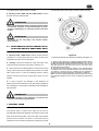
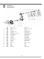
MT-1-MINI,MT-2-MINI,MT-3-MINI
OPERATOR’S MANUAL
MANUAL DE INSTRUCCIONES
NS15A
MT MINI UL
2
10
29
This dispenser is manufactured under one or more of the following U.S.patents and/or other pending patents:
Este aparato está cubierto por una o varias de las siguientes patentes y/o otras solicitudes de patente ya registradas:
U.S.A. 4,900,158
U.S.A. 4,696,417
U.S.A. 5,713,214
U.S.A. 5,906,105
3
MT MINI UL
3 Install the unit on a counter top that will support the
combined weight of dispenser and product bearing in mind
what is stated in the preceding point 1 IMPORTANT
warning.
4 A minimum of 15 cm (6”) of free air space all around the unit
should be allowed to guarantee adequate ventilation.
5 Ensure that the legs are screwed tightly into the base of the
machine.
Replace the standard legs originally installed with the 100 mm
(4”) legs whenever they are provided with the unit.
6 Before plugging the unit in, check if the voltage is the same
as that indicated on the data plate. Plug the unit into a
grounded, protected single phase electrical supply according to
the applicable electrical codes and the specifications of your
machine. When the unit has no plug, install a proper grounded
plug, in compliance with electrical codes in force in your area,
suitable to at least 10 Amp 250 Volt (220-230 Volts 50-60 Hz
areas) and 20 Amp 250 Volt (100-115 Volts 50-60 Hz areas)
applications. Should you prefer to connect the unit directly to
the mains, connect the supply cord to a 2-pole wall breaker,
whose contact opening is at least 0.125”. Do not use extension
cords.
MT 3 MINI
MT 2 MINI
MT 1 MINI
1 TECHNICAL CHARACTERISTICS
1
2
3
Transparent removable bowls
n
1.5
1.5
1.5
Capacity of each bowl, approx. Gal
Dimensions:
width
Inches 7.0625 14.1875 21.25
18.5
18.5
18.5
depth
Inches
height
Inches 25.625 25.625 25.625
44
84
110
Net weight, approx.
Lbs
58
95
119
Gross weight, approx.
Lbs
1
2
3
Adjustable thermostats
n
Hermetic compressor
Air-cooled condenser
Overload protector
Noise level lower than 70 dB (A)
ATTENTION
Failure to provide proper electrical ground according to
applicable electrical codes could result in serious shock
hazard.
IMPORTANT
Read electrical ratings written on the data plate of the
individual units; the data plate is adhered on the dispensing side panel of the unit, just behind the drip tray (the
right side drip tray in multiple bowl models). The serial
number of the unit (preceded by the symbol #) is adhered
inside the left switch box. Data plate specifications will
always supersede the information in this manual.
7 The unit doesn’t come presanitized from the factory. Before
serving products, the dispenser must be disassembled,
cleaned and sanitized according to this handbook instructions
(chapter 5.3 CLEANING AND SANITAZING PROCEDURES).
The electric diagram of the dispenser is located in the inner
part of the dispensing side panel.
IMPORTANT
Install the dispenser so that the plug is easily accessible.
Specifications are subject to change without notice.
2 INTRODUCTION
4 TO OPERATE SAFELY
Please read all sections of this manual thoroughly to familiarize
yourself with all aspects of the unit.
Like all mechanical products, this machine will require cleaning
and maintenance. Besides, dispenser working can be
compromised by operator’s mistakes during disassembly and
cleaning. It is strongly recommended that personnel responsible
for the equipment’s daily operations, disassembly, cleaning,
sanitizing and assembly, go through these procedures in order
to be properly trained and to make sure that no
misunderstandings exist.
1 Do not operate the dispenser without reading this
operator’s manual.
2 Do not operate the dispenser unless it is properly
grounded.
3 Do not use extension cords to connect the dispenser.
4 Do not operate the dispenser unless all panels are
restrained with screws.
5 Do not obstruct air intake and discharge openings: 15 cm
(6”) minimum air space all around the dispenser.
6 Do not put objects or fingers in panels louvers and faucet
outlet.
7 Do not remove bowls, augers and panels for cleaning or
routine maintenance unless the dispenser is disconnected from
its power source.
3 INSTALLATION
1 Remove the corrugate container and packing materials and
keep them for possible future use.
5 OPERATING PROCEDURES
IMPORTANT
ATTENTION
When handling the machine never grasp it by the bowls
or by the evaporator cylinders. The manufacturer refuses
all responsibilities for possible damages which may
occur through incorrect handling.
In case of damages, the power cord must be replaced by
qualified personnel only in order to prevent any shock
hazard.
2 Inspect the uncrated unit for any possible damage. If
damage is found, call the delivering carrier immediately to file a
claim.
1 Clean and sanitize the unit according to the instructions in
this manual. See chapter 5.3 CLEANING AND SANITIZING
4
PROCEDURES.
follows:
2 Fill the bowls with product to the maximum level mark. Do
not overfill.
The exact quantity of product (expressed as liters and gallons)
is shown by marks on the bowl.
3 In case of products to be diluted with water, potable water,
pour water into bowl first, then add correct quantity of product.
In case of natural squashes, it is advisable to strain them, in
order to prevent pulps from obstructing the faucet outlet.
4 To obtain the best performance and result, use bases
designed to be run in Granita freezers. Such bases have a
sugar content of 34 degrees Baumé corresponding to 64
degrees Brix.
For soft drinks the bases are to be diluted with more water, on a
1 plus 5/5.5 basis.
In any case follow the syrup manufacturer’s instructions for
both Granita and soft drink recipes.
If natural juices (e.g. lemon, orange) as well as sugarless
products (e.g. coffee) are used, dissolve 5.3 - 7 oz per 0.25 gal.
figure 2
Power switch (A)
0 position : power is turned OFF to all functions.
I position
IMPORTANT
IMPORTANT
However Granita mix may be done, its Brix (sugar
percent content) must be at least 13.
shown
in
power is turned ON to all functions and the other
switches are enabled. The fan motor runs.
Mixer/refrigeration switch (B)
I position : mixer and refrigeration ON.
SOFT DRINK mode.
Operate the dispenser with food products only.
5 Set the control switches as
5.1 DESCRIPTION OF CONTROLS.
:
0 position :
OFF.
II position :
mixer and refrigeration ON.
GRANITA mode.
Thermostat (D)
Turn clockwise
: to decrease temperature
Turn counterclockwise : to increase temperature
chapter
To operate the unit:
1 Set the power switch to I position.
2 Set the mixer/refrigeration switches as follows:
- to the I position to get soft drink.
- to the II position to get Granita.
6 Always leave the dispenser on, as the refrigeration stops
automatically when Granita reaches the proper thickness. The
mixers will continue to turn.
5. 1 DESCRIPTION OF CONTROLS
5. 2 OPERATION HELPFUL HINTS
The dispenser is equipped with a power switch. In addition each
bowl is individually operated by a mixer/refrigeration switch. In
fact it is possible to dispense both soft drinks and Granita.
When a bowl is in Soft Drink mode the beverage temperature is
controlled by the corresponding thermostat.
When a bowl is in Granita mode the mix viscosity is controlled
by the corresponding adjustment screw located in the rear wall
of each container (for temperature and viscosity setting make
reference to chapter 5.2 OPERATION HELPFUL HINTS).
All the switches are located on the faucet side of the dispenser
in switch panels protected by switch covers (see figure 1).
1 Granita viscosity adjustment: proper Granita viscosity is
factory preset. To change the viscosity, if needed, use a
standard screwdriver to turn the adjustment screw located in
the rear wall of each container as follows (see figure 3):
- towards right (clockwise) to obtain a thicker product (the
indicator F will go down in opening G).
- towards left (counterclockwise) to obtain a thinner product
(the indicator F will go up in opening G).
figure 3
figure 1
2 Beverage temperature adjustment: proper beverage
temperature is factory preset. To reset, turn the knob located in
With reference to figure 3 dispenser controls functions are as
5
MT MINI UL
2 Prior to the disassembly and cleaning, the machine must be
emptied of product. To do this proceed as follows:
- set the power switch to I position
- set mixer/refrigeration switch(es) to I position (Soft Drink
mode)
- place a pail under each faucet and drain all product from
bowls
- set all control switches to the 0 position
each switch box as follows:
- towards right (clockwise) to decrease temperature.
- towards left (counterclockwise) to increase temperature.
Note: beverage temperature is controlled by the
thermostat only when the mixer/refrigeration switch(es)
are in I position, Soft Drink mode.
3 The length of time for freeze down of Granita is governed by
many variables, such as ambient temperature, mix initial
temperature, sugar content (Brix level) and viscosity setting.
4 To shorten Granita recovery time and increase productivity,
it is advisable to pre-chill the product to be used in the
dispenser.
5 To shorten Granita recovery time and increase productivity,
the bowl should be refilled after the product level drops lower
than half of the evaporator cylinder and at the start of each day.
6 For good product conservation the dispenser must run
overnight, at least in Soft Drink mode.
If this is not possible and product is left in the bowls overnight,
the mixer/refrigeration switches must be set to the I position at
least one hour before the unit is switched off. This eliminates
any block of iced product forming overnight, which could result
in damage to mixers or to their motor when the unit is switched
back on. In any case, before the unit is restarted, make sure
that no blocks of ice have been formed; if so, they are to be
removed before the unit is switched on. Overnight operation in
drink mode also eliminates possible ice accumulation from
condensation all around the bowls.
7 Mixers must not be turned off when frozen product is in the
bowl: if not agitated, the product may freeze to a solid block of
ice. If the mixers are turned back on in this situation, damage to
the mixers and their motor may result. Therefore, mixers may
be restarted only after product is melted.
8 The dispenser is equipped with a magnetic coupling by
which the gear motor (located outside the bowl) drives the
mixers (inside the bowl).
The magnetic drive operates as an “intelligent clutch” able
to automatically disconnect the mixers in case they are seized
by ice or other causes.
This inconvenience can be soon noticed since an intermittent
dull noise warns that mixers are still.
In this case it is necessary to unplug immediately the
dispenser, empty the bowl and eliminate the cause of seizing.
9 The dispenser must be able to emit heat.
In case it seems excessive, check that no heating source is
close to the unit and air flow through the slotted panels is not
obstructed by wall or boxes. Allow at least 15 cm (6”) of free
clearance all around the dispenser.
In any case if the product in the bowls is frozen and the
pressure switch warning light is OFF the unit is running
properly.
10 Restrictor cap: when the unit is used in Soft Drink mode it is
advisable to install the restrictor cap on the faucet outlet in
order to reduce the drink outflow (see figure 4).
5. 3. 1 DISASSEMBLY
ATTENTION
Before any disassembly and/or cleaning procedure make
sure that the dispenser is disconnected from its power
source by unplugging it or switching off the 2-pole wall
breaker.
1 Remove cover from the bowl.
2 Remove the bowl by lifting its faucet side up and off the
fastening hooks (see figure 5) and slide it out (see figure 6).
figure 5
figure 4
5. 3 CLEANING AND SANITIZING
PROCEDURES
1 Cleaning and sanitizing of the dispenser are recommended
to guarantee the conservation of the best product taste and the
highest unit efficiency. This section is a procedural guideline
only and is subject to the requirements of the local Health
Authorities.
figure 6
3 Slide the outer spiral out (see figure 7) and then Outside
6
5. 3. 2 CLEANING
magnetic rotor assembly (see figure 8).
IMPORTANT
Do not attempt to wash any machine components in a
dishwasher.
ATTENTION
figure 7
Before any disassembly and/or cleaning procedure make
sure that the dispenser is disconnected from its power
source.
1 Prepare at least two gallons of a mild cleaning solution of
warm (45-60 °C 120-140 °F) potable water and dishwashing
detergent. Do not use abrasive detergent.
Important: if present, follow label directions, as too strong a
solution can cause parts damage, while too mild a solution will
not provide adequate cleaning.
IMPORTANT
figure 8
In order to prevent any damages to the dispenser use
only a detergent suitable with plastic parts.
4 Remove the bowl gasket from its seat (see figure 9).
2 Using a brush, suitable for the purpose, thoroughly clean all
disassembled parts in the cleaning solution.
ATTENTION
When cleaning the machine, do not allow excessive
amounts of water around the electrically operated components of the unit. Electrical shock or damage to the
machine may result.
3 Do not immerse the lighted top covers in liquid. Wash them
apart with the cleaning solution. Carefully clean their
undersides.
4 In the same manner clean the evaporator cylinder(s) using
a soft bristle brush.
5 Rinse all cleaned parts with cool clean water.
figure 9
5 Dismantle the faucet assembly (see figure 10).
5. 3. 3 SANITIZING
Sanitizing should be performed immediately prior to
starting the machine. Do not allow the unit to sit for
extended periods of time after sanitization.
1 Wash hands with a suitable antibacterial soap.
2 Prepare at least two gallons of a warm (45-60 °C 120140 °F) sanitizing solution (100 PPM available chlorine
concentration or 1 spoon of sodium hypoclorite diluted with 0.5
gal of water) according to your local Health Codes and
manufacturer’s specifications.
3 Place the parts in the sanitizing solution for five minutes.
4 Do not immerse the lighted top covers in liquid. Carefully
wash their undersides with the sanitizing solution.
5 Place the sanitized parts on a clean dry surface to air dry.
6 Wipe clean all exterior surfaces of the unit. Do not use
abrasive cleaner.
figure 10
6 Slide the drip tray out and empty it.
7
MT MINI UL
5. 3. 4 ASSEMBLY
end of the magnetic outside rotor (see figure 14).
1 Slide the drip tray into place.
2 Lubrificare il pistone rubinetto e il rotore magnetico esterno
(see points A, B and C of figure 11) only with the grease
supplied by the manufacturer or other food grade approved
lubricant.
figure 14
7 Push the bowl towards the rear wall of the unit until it fits
snugly around the gasket and its front fastening hooks are
properly engaged (see figure 15).
figure 11
3 Assemble the faucet by reversing the disassembly steps
(see figure 10)
4 Fit bowl gasket around its seat.
Note: the largest brim of gasket must face against the rear wall
(see figure 12).
figure 15
8 Use fresh product to chase any remaining sanitizer from the
bottom of the bowl(s). Drain this solution. Do not rinse out the
machine.
5. 4 IN-PLACE SANITIZATION
figure 12
The In-Place Sanitization prior to starting the machine may
be performed, if needed, only as further precaution, in
addition to the Disassembled Parts Sanitization described
before, but never in lieu of it.
1 Prepare two gallons of a warm (45-60°C, 120-140 °F)
sanitizing solution (100 PPM available chlorine concentration or
1 spoon of sodium hypoclorite diluted with 0.5 gal of water)
according to your local Health Codes and manufacturer’s
specifications.
2 Pour the solution into the bowl(s).
3 Using a brush suitable for the purpose, wipe the solution on
all surfaces protruding above the solution-level and on the
underside of the top cover(s).
4 Install the top cover(s) and operate the unit. Allow the
solution to agitate for about two minutes. Drain the solution out
of the bowl(s).
5 Use fresh product to chase any remaining sanitizer from the
bottom of the bowl(s). Drain this solution. Do not rinse out the
machine.
5 Insert the magnetic outside rotor in the evaporator taking
care to accompany it to the end (see figure 13).
6 ROUTINE MAINTENANCE
figure 13
1 Daily: inspect the machine for signs of product leaks past
seals and gaskets. If proper assembly does not stop leaks
around seals or gaskets, check for improper lubrication, worn
6 Install the outer spiral. Slide it over the evaporator until its
hexagonal front notch engages with the hexagonal exposed
8
automatically freezes down again to Granita setting viscosity.
or damaged parts. Replace parts as needed.
2 Monthly on MT 2 MINI and MT 3 MINI models: remove
the dust from the condenser filter.
ATTENTION
Before any disassembly and/or cleaning procedure make
sure that the dispenser is disconnected from its power
source by unplugging it or switching off the 2-pole wall
breaker.
ATTENTION
Condenser fins are very sharp. Use extreme caution
when cleaning.
6. 1 MAINTENANCE (TO BE CARRIED OUT BY
QUALIFIED SERVICE PERSONNEL ONLY)
1 Monthly on MT 1 MINI model: remove the dust from the
figure 16
condenser. To do this unplug the unit or switch off the 2-pole
To operate the defrost timer proceed as follows (see figure 16).
wall breaker and then remove the panels.
1 Set the time of the day by rotating the dial clockwise (arrow
A). Never rotate the timer counterclockwise as this would
damage the internal mechanism. Align the current time of day
with the arrow B on the timer face. This is a 24 hour timer
showing both A.M. and P.M.
2 Program the defrost timer by pushing out on the tabs C that
correspond to the hours desired to defrost. Each tab represents
15 minutes. A minimum of four to eight hours are required to
defrost frozen beverage (depending on ambient conditions).
Note: when all the tabs are pushed in the defrost function is OFF
(the machine operates as if it were not equipped with Defrost
Timer).
2 Annually: remove the panels and clean the inside of the
machine including the base, side panels, condenser, etc.
3 Never remove the insulating jacket from around the suction
tubing of the evaporator (the copper tubing located on the right
side of gear motor). In case the insulating jacket is missing
replace the entire parts with original spare parts from the
supplier.
4 In order to prevent any damages to the dispenser, all
plastics parts must be lubricated only with grease supplied by
the manufacturer or with another lubricating product suitable for
polycarbonate.
IMPORTANT
The electric diagram of the dispenser is located in the
inner part of the dispensing side panel.
7 DEFROST TIMER
The Defrost Timer, located on the right side of the unit,
automatically switches the dispenser from Granita mode to Soft
Drink mode and the opposite. This means that during defrost
periods frozen Granita will melt to thermostat setting
temperature and once defrost period has expired, the product
9
2 Controlar que el distribuidor no haya sufrido daños durante
el transporte. De haberlos sufrido, reclamar inmediatamente al
transportista.
3 Colocar el distribuidor en un mostrador en grado de
sostener su peso incluso con la carga completa, teniendo en
cuenta cuanto indicado en IMPORTANTE, del punto 1.
4 Dejar un espacio libre de por lo menos 6” alrededor del
aparato para no impedir el flujo de aire de refrigeración.
5 Controlar la estabilidad del aparato, regulando la altura de
los pies. En el caso en que el distribuidor esté provisto de una
serie de piés altos (4” aproximadamente), ésta debe ser
sustituida a la original.
6 Antes de enchufar el aparato con la toma de corriente
controlar que la tensión de la red sea aquella indicada en la
placa. Enchufar el distribuidor a una red monofásica,
sirviéndose de una toma completa de tierra, según lo previsto
por la normativa vigente. Si el distribuidor resulta desprovisto
de enchufe, conectar al cable un enchufe que esté en
conformidad con las normas vigentes de vuestro país, provisto
de espiga o contactos de tierra y adecuado para corrientes de
por lo menos 10A y tensión de 250V (para áreas con tensiones
de 220V-230V, 50Hz-60Hz) y 20 A y tensión de 250V (para
áreas con tensiones de 110V-115V 50-60Hz). En el supuesto
de realizar una conexión fija a la red, conectar el cable a un
interruptor de pared de tipo bipolar con apertura de contactos
de 0.125” por lo menos. No utilizar cordones conectores para
enchufar el aparato al suministro de corriente eléctrica.
MT MINI 3
MT MINI 2
1 CARACTERISTICAS TECNICAS
MT MINI 1
MT MINI UL
n
1
2
3
Contenedores
transparentes
desmontables
1.5
1.5
1.5
Capacidad de cada contenedor, Gal
aproximada
Dimensiones:
Inches 7.0625 14.1875 21.25
ancho
Inches
18.5
18.5
18.5
largo
Inches 25.625 25.625 25.625
alto
Lbs
44
84
110
Peso neto, aproximado
Lbs
58
95
119
Peso bruto, aproximado
n
1
2
3
Termostatos regulables
Motocompresor hermético
Condensador a ventilación forzada
Guardamotor
Nivel de ruido inferior a 70dB (A)
IMPORTANTE
ATTENCION
Características eléctricas: leer los datos detallados en la
placa del distribuidor; ésta se encuentra en la parte inferior del panel frontal, detrás del cajón recoge-gotas de la
derecha. Los números de matrícula de los aparatos (precedidos por el símbolo#) están colocados dentro del
alojamiento portatinterruptores de izquierda. Los datos
detallados sobre la placa son aquellos a los que se debe
siempre hacer referencia.
Cerciorarse que el aparato esté correctamente
conectado a tierra; en caso contrario es posible causar
shock eléctricos a las personas o dañar el distribuidor.
7 El distribuidor no sale de fábrica prelavado e higienizado.
Antes de utilizarlo debe ser desarmado, lavado e higienizado
siguiendo cuanto se ha dicho en las presentes instrucciones
del capítulo 5.3 LIMPIEZA.
El diagrama eléctrico del distribuidor se encuentra dentro
del panel lado grifo.
Se reserva el derecho de efectuar modificaciones sin previo
aviso.
4 PARA UN FUNCIONAMIENTO SEGURO
1 No utilizar el distribuidor antes de haber leído el presente
manual de instrucciones.
2 No utilizar el distribuidor si no está correctamente
conectado a tierra.
3 No utilizar cordones conectores para enchufar el
distribuidor al suministro de corriente.
4 No poner en funcionamiento el distribuidor si los paneles no
se encuentran en su lugar y fijados con los tornillos.
5 No impedir el flujo de aire de refrigeración, dejar un espacio
libre de por lo menos 6” alrededor del distribuidor.
6 No introducir los dedos u objetos en las ranuras de los
paneles y en la apertura del grifo.
7 No desmontar el contenedor, no quitar los mezcladores o
paneles para limpieza o manutención sin cerciorarse que el
distribuidor esté desenchufado del suministro de corriente.
2 INTRODUCCION
Les aconsejamos que lean atentamente este manual de
instrucciones para conocer todas las características del
distribuidor.
También este distribuidor, como todos los productos
mecánicos, necesita de limpieza y cuidado. Se corre el riesgo
de impedir su buen funcionamiento si se verificasen errores
cometidos por el usuario durante la fase de desmontaje y
limpieza. Por dicho motivo es importante que los
procedimientos de desmontaje, lavado, higienización y
limpieza, siendo operaciones cotidianas, sean conocidas sin
posibilidad de error por todo el personal responsable del
distribuidor.
5 INSTRUCCIONES DE EMPLEO
3 INSTALACIÓN
1 Quitar el distribuidor del embalaje: guardar este último por
si hubiera cualquier eventualidad.
ATTENCION
Si el cable de alimentación está dañado, debe ser substituito por el fabricante o desde su servicio de asistencia
técnica o, en cualquier caso, por una persona cualificada
con el fin de evitar cualquier tipo de riesgo.
IMPORTANTE
En la operación de transporte o levantamiento no se
debe coger nunca el distribuidor por sus contenedores
transparentes o por los cilindros evaporadores.
El fabricante no responde de los daños acarreados por
estas maniobras equivocadas.
1 Lavar e higienizar el distribuidor antes de utilizarlo
siguiendo cuanto se ha dicho en las presentes instrucciones en
el capítulo 5.3 LIMPIEZA.
2 Llenar los contenedores con el producto deseado hasta
10
que alcance el nivel máximo indicado (no superar dicho nivel).
La cantidad de producto presente en el contenedor (en litros o
en galones) está indicada con señales específicas situadas en
el contenedor mismo.
apropiada (ver figura 1).
3 Si se quiere distribuir productos concentrados a diluirse con
agua, verter en los contenedores el agua agregando a
continuación la cantidad necesaria de producto concentrado,
según las instrucciones del fabricante. Si se quieren emplear
zumos naturales se recomienda filtrarlos para evitar que las
partes sólidas puedan obstruir el pasaje del grifo.
4 Para obtener los mejores resultados emplear como
productos base, jarabes expresamente preparados para
Granizado.
Si se desea obtener una bebida en vez de un granizado, cada
litro de jarabe debe ser diluido con 1.3-1.5 gal de agua (0.25
gal más respecto del necesario para el granizado).
Es una buena regla seguir las instrucciones dictadas por el
fabricante de jarabes.
Si se usan productos naturales (por ejemplo zumo de limón o
naranja) o bien bebidas no azucaradas (por ejemplo café),
disolver 5.3-7 oz per 0.25 gal azúcar por cada litro de producto.
figura 1
Las funciones de los mandos del distribuidor se ilustran a
continuación:
IMPORTANTE
En todo caso, una vez obtenida la mezcla, su grado de
Brix (porcentaje de azúcar) debe ser superior a 13.
IMPORTANTE
figura 2
Utilizar el distribuidor solamente con productos alimenticios.
Interruptor general (A)
Posición 0
: el distribuidor está apagado.
5 Accionar los interruptores (ver capítulo 5.1 DESCRIPCIÓN
DE LOS MANDOS).
Posición I
6 El distribuidor debe funcionar siempre con las tapas
montadas para prevenir una posible contaminación del
producto.
Interruptor mezcladores y refrigeración (B)
Posición I
: mezcladores y refrigeración en función.
Posición BEBIDA.
7 El distribuidor debe funcionar ininterrumpidamente: el
sistema de refrigeración de cada contenedor se parará
automáticamente cuando el producto esté listo para ser
distribuido. Los dispositivos mezcladores seguirán
funcionando.
5. 1
: el distribuidor está habilitado para el
funcionamiento. Ventilador en función.
Posición 0
: mezcladores y refrigeración apagados.
Posición II
: mezcladores y refrigeración en función.
Posición GRANIZADO.
Termostato (D)
Rotación en sentido horario
DESCRIPCION DE LOS MANDOS
Rotación en sentido antihorario
: bebida más fría
: bebida menos fría
Para el funcionamiento del distribuidor:
1 Colocar el interruptor general en la posición I.
2 Ajustar los interruptores mezcladores y refrigeración:
- en la posición I si se quiere refrigerar el producto sin helarlo
- en la posición II si se quiere obtener el granizado.
El distribuidor está provisto de un interruptor general. Cada uno
de los contenedores está provisto de un interruptor para
arrancar la mezcla y para seleccionar el tipo de refrigeración del
producto. En efecto, es posible obtener tanto bebidas frías
como productos helados como granizados o sorbetes.
5. 2
Cuando se selecciona la función bebida, la temperatura de
dicha bebida está regulada por el correspondiente termostato.
Cuando se selecciona la función granizado la densidad del
producto se regula con el correspondiente tornillo de ajuste que
se encuentra en cada una de las paredes posteriores del
distribuidor (para regular la temperatura y la densidad ver el
capítulo 5.2 SUGERENCIAS).
SUGERENCIAS
1 Regulación de la densidad: la densidad óptima del
granizado ha sido ya ajustada en fábrica. Si se quiere variar
dicha densidad girar con un destornillador el correspondiente
tornillo de ajuste situado en cada una de las paredes
posteriores del distribuidor (ver figura 3):
- hacia derecha (sentido horario) para obtener un granizado
más denso (el índice F en la ventanilla G se desplazará
hacia abajo).
- hacia izquierda (sentido antihorario) para obtener un
Todos los interruptores están colocados en la parte frontal del
distribuidor (lado grifos) y están protegidos con una ventanilla
11
MT MINI UL
particular, cerca de las rejillas de los paneles. Cerciorarse
además, que el flujo de aire no esté obstaculizado por paredes
cercanas, cajas u otras cosas. Dejar por lo menos 15 cm de
espacio libre alrededor del distribuidor.En todo caso cuando el
producto dentro de los contenedores está helado y la lamparilla
del limitador de presión de seguridad está apagada es seguro
que todo funciona regularmente y que el calor emitido no es
dañoso.
granizado menos denso (el índice F en la ventanilla G se
desplazará hacia arriba).
10 Reductor del flujo: cuando el distribuidor se utiliza para la
refrigeración de bebidas se aconseja instalar, sobre el grifo, el
reductor de flujo provisto (ver figura 4).
figura 3
2 Regulación de la temperatura: la temperatura óptima de
las bebidas (para el funcionamiento del distribuidor como
refrigerador de bebidas y no como granizador) ha sido
regulada en la fábrica. Si se quiere variar su valor, girar el
pomo colocado en cada una de los paneles portainterruptores:
- hacia derecha (sentido horario) para obtener una bebida
más fría.
- hacia izquierda (sentido antihorario) para obtener una
bebida menos fría.
NOTA : la regulación de la temperatura de la bebida se
hace efectiva solamente cuando el interruptor
mezcladores y refrigeración correspondiente se
encuentra en la posición Bebida.
3 El tiempo necesario para obtener la refrigeración del
producto varía en función de distintos factores como por
ejemplo la temperatura ambiente, la temperatura inicial del
producto, su contenido de azúcar (grado Brix) y la regulación
de la densidad.
4 Llenando los contenedores con producto ya enfriado
previamente se aumenta ulteriormente la eficiencia del
distribuidor.
5 Para disminuir los tiempos de restablecimiento y, por lo
tanto, aumentar la autonomía del distribuidor, volver a llenar
cuando el nivel del producto desciende a mitad evaporador.
6 Para conseguir una buena conservación del producto, el
distribuidor debe funcionar también durante la noche, por lo
menos en la posición Bebida. Si esto no fuera posible y los
productos permanecieran en los contenedores con el
distribuidor parado es conveniente, una hora antes de apagar
el aparato, llevar los interruptores mezcladores y refrigeración
en la posición I; ésto evita la formación de bloques o crostas de
hielo que podrían dañar los dispositivos mezcladores. En el
caso en que se formasen dichos bloques de hielo, estos
deberían ser quitados antes de volver a poner en función el
distribuidor. El funcionamiento nocturno en la posición Bebida
elimina además la posible formación de hielo (debido a la
condensación de la humedad atmosférica) en el exterior de los
contenedores.
7 No parar jamás los mezcladores cuando hay granizado en
los contenedores; si no se mezcla, dicho granizado puede
agregarse y formar un único bloque de hielo. Volviendo a
arrancar los mezcladores en estas condiciones (sin esperar
que el hielo se derrita) pueden dañarse.
8 El distribuidor está provisto de una junta magnética para la
transmisión del movimiento a los mezcladores.Para prevenir
daños al aparato, en caso de bloqueo de los mezcladores
debido a bloques de hielo u otro dentro de los contenedores, la
junta magnética se encarga de desconectar automáticamente
la transmisión del movimiento.
Dicha situación puede ser identificada tanto por el bloqueo de
los mezcladores como por un ruído intermitente que proviene
del aparato. En este caso es necesario parar inmediatamente
el distribuidor, vaciar el contenedor interesado y eliminar la
causa del bloqueo.
9 Todo distribuidor de este tipo debe despedir calor. Si el
calor producido fuera excesivo, controlar que ninguna fuente
de calor se encuentre cerca del distribuidor y, en modo
figura 4
5. 3
LIMPIEZA
1 La limpieza y el lavado son fundamentales para garantizar
la perfecta conservación del gusto de la bebida y la máxima
eficiencia de vuestro distribuidor. Los procedimientos descritos
a continuación deben ser considerados de carácter general y
pueden variar por efecto de la reglamentación de higiene
vigente.
2 Antes del desarmado para el lavado del distribuidor debe
quitarse todo el producto. Proceder como sigue:
- poner el interruptor general en la posición I;
-
poner los interruptores mezcladores/refrigeración en la
posición I;
-
posicionar un recipiente debajo del grifo y vaciar los
contenedores;
-
poner todos los interruptores en la posición 0.
5. 3. 1
DESMONTAJE
ATTENCION
Antes de proceder con el desmontaje de cualquier componente, desenchufar de la toma de corriente eléctrica el
enchufe del aparato o bien apagar el interruptor externo
de pared.
1 Quitar la tapa del contenedor.
2 Desmontar el contenedor empujando ligeramente la parte
inferior (lado grifo) hacia arriba para dejar libres los ganchos
inferiores (ver figura 5) y luego quitarlo por adelante (ver figura
12
4 Quitar de su alojamiento la junta del contenedor (ver figura
9).
6).
figura 9
5 Desarmar el grifo respetando la secuencia indicada (ver
figura 10).
figura 5
figura 10
6 Desenfilar el cajón recoge-gotas y vaciarlo.
figura 6
5. 3. 2
3 Desenfilar del evaporador el rascador exterior (ver figura 7)
y después el Rotor magnetico externo completo (ver figura 8).
LAVADO
IMPORTANTE
No lavar ningún componente de la maquina en lavavajillas.
ATTENCION
figura 7
Antes de efectuar cualquier tipo de limpieza, desenchufar de la toma de corriente eléctrica el enchufe del aparato o bien apagar el interruptor externo de pared.
1 Poner en una palangana aproximadamente ocho litros de
agua caliente (120-140 F) y detergente respetando con
atención las instrucciones del fabricante; una solución
demasiado concentrada del detergente puede provocar daños
en las partes a lavar, en vez una solución demasiado diluida
puede no limpiar bastante. No utilizar detergentes abrasivos.
IMPORTANTE
Para prevenir daños al distribuidor utilizar solamente un
detergente compatible com las partes de plastico.
figura 8
13
MT MINI UL
2 Emplear un cepillo apropiado y lavar minuciosamente con
la solución detergente todas las partes en contacto con la
bebida.
pared posterior (ver figura 12).
ATTENCION
Durante el lavado del distribuidor no usar mucha cantidad de agua cerca de los componentes eléctricos; en
caso contrario es posible que se verifiquen shock eléctricos o bien se dañe el distribuidor.
3 No sumergir en la solución de lavado las tapas con luz sino
que lavarlas en modo separado. Prestar mucha atención a sus
lavados en la parte inferior.
4 Lavar los cilindros evaporadores empleando un cepillo con
cerdas suaves.
5 Enjuagar todas las partes con agua corriente.
5. 3. 3
figura 12
5 Insertar el rotor magnetico externo en el evaporador,
acompañándolo con cuidado (ver figura 13).
HIGIENIZACION DEL DISTRIBUIDOR
DESMONTADO
La higienización debe efectuarse inmediatamente antes de
p on er en f unc ión el d ist r ib ui dor ; evi t ar que e ste
permanezca inactivo por mucho tiempo despúes de haber
sido higienizado.
1 Antes de iniciar los procedimientos descritos a continuación
lavarse las manos con un jabón antibactérico.
2 Poner en una palangana aproximadamente ocho litros de
solución de agua caliente (120-140 F) con un producto para
higienizar aprobado por las autoridades de vuestro país
respetando las especificaciones del fabricante. Si se carece de
un producto para higienizar específico, preparar una solución
de agua e hipoclorito de sodio (lejía uso alimenticio) en la
proporción de 1 cucharadita por cada 0.5 gal de agua.
3 Colocar en la solución todas las partes a higienizar
dejándolas el tiempo que ha sido indicado por el fabricante del
producto.
4 No sumergir en la solución las tapas con la luz. Lavar muy
minuciosamente la parte inferior con la solución para
higienizar.
5 Dejar secar las partes higienizadas, sobre una superficie
limpia al aire libre.
6 Secar las partes externas del distribuidor sin usar paños
abrasivos.
5. 3. 4
figura 13
6 Colocar sobre el evaporador el rascador exterior acoplando
su extremidad anterior al arbol del rotor magnetico externo
(ver figura 14).
REMONTAJE
figura 14
1 Colocar el cajón recoge-gotas en su alojamiento.
2 Lubricar el pistón grifo, el rascador interior y el rotor
magnetico (en los puntos A, B y C indicados en la (ver figura
11) utilizando solamente la grasa suministrada por el fabricante
u otro grasa para uso alimenticio.
7 Montar el contenedor y empujarlo hacia la pared posterior,
controlando que calce completamente en la junta y, al mismo
tiempo, que sus ganchos inferiores coincidan con las
correspondientes salientes del plano de goteo (ver figura 15).
figura 11
3 Armar de nuevo el grifo sobre el contenedor siguiendo la
secuencia inversa a la detallada para el desmontaje (vedere
figura 10).
4 Volver a montar en su alojamiento la junta del contenedor.
NOTA: El borde de mayor diámetro debe ser apoyado enla
figura 15
14
8 Enjuagar con bebida fresca para eliminar todo residuo
posible de solución para higienizar del fondo de los
contenedores. Secar la parte interior de los contenedores con
una servilleta de papel desechable.
3 No quitar jamás el material aislante contra la condensación
puesto alrededor del tubo de salida del evaporador (el tubo de
cobre colocado a la derecha del motoreductor). Si dicho
material estuviera dañado o perdido, reponer con recambios
originales del fabricante.
5. 4
4 Para prevenir daños al distribuidor las partes de plástico
deben ser lubricadas solamente con la grasa suministrada por
el fabricante u otra grasa compatible con policarbonato.
HIGIENIZACION DEL DISTRIBUIDOR
MONTADO
La higienización del aparato montado, antes de ser puesto
en funcionamiento, puede ser efectuada, si es necesario,
solamente como una ulterior prevención adicional a la
higienización del aparato desmontado descrito
anteriormente, pero no debe sustituir jamás a la efectuada
con el aparato desmontado.
1 Poner en una palangana una solución de agua u producto
para higienizar aprobado por las autoridades de vuestro país,
respetando las especificaciones del fabricante. Si se carece de
un producto para higienizar específico, preparar una solución
de agua e hipoclorito de sodio (lejía uso alimenticio) en la
proporción de 1 cucharadita por cada 2 litros de agua.
2 Verter la solución en los contenedores.
3 Usando un cepillo apropiado fregar con la solución todas
las partes sobre el nivel de la solución y sobre la parte inferior
de la tapa.
4 Colocar la tapa y poner en función el distribuidor de modo
que permita a la solución agitarse 2 minutos.
5 Vaciar los contenedores de la solución para higienizar por
medio de los grifos.
6 Enjuagar con bebida fresca para eliminar del fondo de los
contenedores todo residuo posible de solución para higienizar.
Secar la parte interior de los contenedores con una servilleta
de papel desechable.
7 No efectuar más operaciones de enjuague.
IMPORTANTE
El diagrama eléctrico del distribuidor se ilustra en
la parte interior del panel del lado grifo.
7 CONTADOR DE DESCONGELACION
El contador de descongelación, que está situado a la derecha
del aparato, automaticamente cambia el dispensador de la
función del Granizado a la función Bebida y al contrario. Esto
quiere decir que durante el periodo de descongelación el
Granizado se derretirá a la temperatura fijada por el termostato
y una vez que el periodo de descongelación haya terminado, el
producto automáticamente se congela de nuevo a la viscosidad
prefijada del Granizado.
6 MANUTENCION
1 Cada día: controlar el distribuidor y que no se verifiquen
pérdidas de producto de las juntas. Si se notasen pérdidas,
controlar , antes de todo, que el distribuidor esté montado
correctamente, luego que las juntas no necesiten lubricación y,
por último, que dichas juntas no sean defectuosas o estén
gastadas, si es así reemplazarlas con recambios originales del
fabricante.
2 Cada mes en los modelos MT 2 MINI y MT 3 MINI:
eliminar el polvo que se acumula sobre el filtro del
condensador.
ATTENCION
Antes de efectuar cualquier tipo de limpieza, desenchufar de la toma de corriente eléctrica el enchufe del aparato o bien apagar el interruptor externo de pared.
figura 16
Para utilizar el contador de descongelación seguir los siguientes
pasos (ver figura 16):
ATTENCION
1 fijar la hora del día girando el contador en sentido horario.
Nunca girar el contador en sentido antihorario ya que el
mecanismo interno podria verse dañado. Alinear la hora del día
mediante la aguja B situada en la cara del contador. Este es un
contador que muestra las 24 horas AM y PM.
Prestar atención a las aletas del condensador porque tienen filo.
6. 1
MANUTENCION (SOLAMENTE POR EL
SERVICIO POSTVENTA)
2 programar el contador de descongelación presionando las
lenguetas indicadas con la letra “C” que corresponden a las
horas prefijadas para la descongelación. Cada división
representa 15 minutos. Un minimo de cuatro a ocho horas son
necesarias para la descongelación de la bebida (dependiendo
de las condiciones ambientales).
1 Cada mes en el modelo MT 1P MINI: eliminar el polvo que
se acumula sobre el condensador. Antes de efectuar cualquier
tipo de limpieza, desenchufar de la toma de corriente eléctrica
el enchufe del aparato o bien apagar el interruptor externo de
pared,a continuación desmontar los paneles.
2 Cada año: es aconsejable quitar todos los paneles y limpiar
la zona interior, incluso la base y el interior de los paneles.
Note: quando todas las lenguetas no están presionadas la
función de descongelación se mantiene apagada (el distribuidor
funciona como si no estubiera equipado con el contador de
descongelación).
15
MT MINI UL
SPARE PARTS LIST
DESCRIPCION PIEZAS DE REPUESTO
16
2416_29 V 0.3 07N17
1
2
3
4
5
6
7
8
9
10
11
12
13
14
15
16
17
18
19
20
21
22
23
24
25
26
27
28
29
30
31
32
33
34
35
36
37
38
39
40
40
41
42
43
44
45
46
47
48
49
50
51
52
54
55
00687
00688
00689
00690
00691
00692
00447
00420
00101
00103
00134
00109
00537
00237
00269
00693
00092
00694
00695
00696
00697
00698
00699
00228
00129
00562
00700
00182
00130
00282
00124
00133
00132
00297
00265
PPP
00532
00564
00565
00298
00108
00179
00158
00449
00701
00463
>>>
00702
00105
00703
00704
00121
00150
00705
00706
Cover fixing plate
Cover
Picture
Complete cover
Bowl
Faucet handle
Faucet handle spring
Faucet piston
Faucet piston OR
Faucet handle pin
Restrictor cap
Thrust washer rubber cap
Thrust washer
Left side panel
Timer switch
Evaporator insulating material
4” leg
Evaporator rotor housing
Scraper bushing
Rotor housing O-ring
Outside magnetic rotor assembly
Evaporator front gasket
Outer spiral
Magnetic drive
Switch box
Switch panel cover
Evaporator screw stay
Thermostat knob
Power switch box
3-position switch
Switch
Fan blade
Thermostat
Terminal block protection
Terminal block with cable clamp
Dispensing side panel
Stainless steel fixing screw for panel
Drip tray cover
Drip tray
Fan motor MINI 1 GL
Fan motor MINI 2 / 3 GL
Clip
Rubber leg
PWB housing
Delay electronic device
Solenoid valve plastic cap
Solenoid valve coil
Shaft
Bowl gasket
Evaporator back gasket
Micro-switch protection
Microswitch
Grey front bushing
Thermostat probe holder
Gear motor
Placa para tapa
Tapa
Fotografia
Tapa
Contenedor
Palanca grifo
Muelle de la palanca grifo
Pistón del grifo
Junta OR del pistón grifo
Pivote de la palanca
Tapa de restricción
Tapa de goma para buje
Arandela de empuje
Panel lateral izquierdo
Contador de descongelación
Espuma aislante para evaporador
4” pie nivelador
Base rotor evaporador
Buje para rascador
O-ring para rotor
Rotor magnetico externo completo
Junta anterior evaporador
Rascador exterior
Rotoe interior
Panel para interruptores
Tapa panel interruptores
Tirante evaporador
Pomo para termostato
Panel para interruptor general
Interruptor de 3 posiciones
Interruptor
Aspas
Termostato
Protección pasacable
Pasacable
Panel lado grifo
Tornillo inox fijacion paneles
Rejilla cajón recoge-gotas
Cajón recoge-gotas
Motor ventilador MINI 1 GL
Motor ventilador MINI 2 / 3 GL
Clip
Pie nivelador
Soporte circuito electrónico
Circuito electronico
Protecciòn de plastico para bobina electrovalvula
Bobine electrovàlvula
Eje
Junta del contenedor
Junta posterior evaporador
Goma de protección microinterruptor
Microinterruptor
Buje gris anterior
Lleva sonda termostato
Motoreductor
17
MT MINI UL
56
57
58
59
60
61
62
63
64
65
66
00153
00088
00452
00087
00573
00569
00707
00575
PPP
00157
00526
Rear bushing
Spring
Shaped nut
Density adjustment screw
Rear cover
Rear cover fixing screw
Rear cover picture
Rear cover picture screen
Back panel
Timer cover
Right side panel
Buje posterior
Muelle
Tuerca-guida del muelle
Tornillo regulador densidad
Tapa posterior
Tornillo de fijación de la tapa
Fotografia para tapa posterior
Armazón para fotografia tapa posterior
Panel posterior
Tapa para timer
Panel lateral derecho
>>>
PPP
Please order what printed on piece
See table
Pedir com la identificación marcada en la pieza
Ver tabla
PPP
36
64
MT 1 MINI
00239
00235
MT 2 MINI
00240
00236
MT 3 MINI
00241
00276
18
GEAR MOTOR
MOTORREDUCTOR
1
00097
Bracket with bush
2
00156
Stator
Soporte con buje
Estator
3
00296
Stator protection gasket
Junta de la cobertura estador
4
00168
Washer
Arandella
5
00253
Rotor spacer
Distancial del rotor
6
00190
Gear box with bushing
Caja reductor con buje
7
00256
Seal retainer
Junta de retencion
8
00254
Ball bearing ∅ 28 mm rubber cap
Tapa de goma para cojinete
9
00255
Central shaft OR
OR para eje central
10
00247
Ball bearing ∅ 28 mm
Cojinete de bolas ∅ 28
11
00257
1.5 mm spacer
Distancial 1,5 mm.
12
00184
Third gear
Tercero engranaje
13
00388
Fourth gear
Cuarto engranaje
14
00258
3.3 mm spacer
Distancial 3,3 mm.
15
00224
Bushing rubber cap
Tapa de goma para buje
17
00164
First gear
Primero engranaje
18
00167
Second gear
Segundo engranaje
19
00636
Gasket
Junta
20
00189
Gear box cover
Tapa de la caja reductor
22
00180
Rotor
Rotor
23
00187
Pinion
Piñón
24
00169
Bushing
Buje
25
00170
Washer
Arandela
26
00262
Bracket screw
Tornillo del estador
19
CECILWARE CORPORATION
43-05 20th Avenue
Long Island City, N.Y. 11105
Tel. (800) 935 2211
Fax (718) 932 7860
[email protected]
www.cecilware.com
2416_49 R0.3 07N17