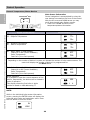
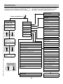
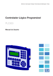
1
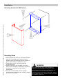
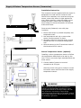
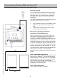
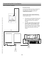
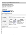
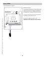
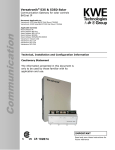
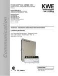
Versatronik® 300 Cascade Control Cascade Control 704083 w/o BACnetIP 704092 with BACnetIP Applicable Controls Vitotronic 100, GC1/GC1B Vitotronic 300, GW2 Vitotronic 300, GW5B Vitotronic 200, HO1/HC1 Vitodens 200 B2HA Technical, Installation and Configuration Information Cautionary Statement The information presented in this document is only to be used by those familiar with its application and use. IMPORTANT Read and save these instructions for future reference About these instructions ! Take note of all symbols and notations intended to draw attention to potential hazards or important product information. These include “WARNING”, “CAUTION” and “IMPORTANT”. See below. ! WARNING KWE P/N 394031 Versatronik 300 Cascade Control V1.4 04/2014 Technical information subject to change without notice Indicates an imminently hazardous situation which, if not avoided, could result in death, serious injury or substantial product/property damage. ! CAUTION Indicates an imminently hazardous situation which, if not avoided, may result in minor injury or product/property damage. Warnings draw your attention to the presence of potential hazards or important product information. Cautions draw your attention to the presence of potential hazards or important product information CAUTION Static sensitive components may be damaged by improper handling or work within the control. Ensure all possible measures are taken to eliminate build-up of static electricity. IMPORTANT Helpful hints for installation, operation or maintenance which pertains to the product. Trademark Information Viessmann® and Vitotronic® are trademarks of Viessmann Werke GmbH & Co KG registered in the United States and other countries. Please visit: www.viessmann.ca www.viessmann.us Echelon®, LON®, LONWORKS®, i.LON®, LNS®, LONMARK®, Neuron®, and the LonUsers logo are trademarks of Echelon Corporation registered in the United States and other countries. Please visit: www.echelon.com BACnet® is a registered trademark of the American Society of Heating, Refrigerating and AirConditioning Engineers, Inc., 1791 Tullie Circle NE, Atlanta, GA 30329. For more information please visit: www.bacnet.org www.ashrea.org 2 Important Regulatory and Installation Requirements Codes The installation of this unit must be in accordance with local codes. KWE P/N 394031 Versatronik 300 Cascade Control V1.4 04/2014 Technical information subject to change without notice All electrical wiring is to be done in accordance with the latest edition of CSA C22,1 Part 1 and/ or local codes. In the U.S. use the National Electrical Code ANSI/NFPA 70. The installing contractor must comply with the Standard of Controls and Safety Devices for Automatically fired Boilers, ANSI/ ASME CSD-1 where required by the authority having jurisdiction. Working on the equipment The installation, adjustment, service and maintenance of this unit must be done by a licensed professional heating contractor or persons who are qualified and experienced in the installation, service, and maintenance of similar products. There are no user serviceable parts on this control. Power supply Install power supply in accordance with the regulation of the authorities having jurisdiction or in absence of such requirements, in accordance with National Codes. Purpose of Device and Operation The Versatronik 300 Cascade control is designed to stage Viessmann LON enabled boilers and boiler controls via a CAT5 wire connection LON communication. 3 Please carefully read this manual prior to attempting installation. Any warranty is null and void if these instructions are not followed. The completeness and functionality of field supplied electrical controls and components must be verified by those installing the device ! WARNING More than one live circuit. See wiring diagram in this manual. Turn off power supply to control and damper/blower before servicing. Contact with live electrical components can result in serious injury or death KWE P/N 394031 Versatronik 300 Cascade Control V1.4 04/2014 Technical information subject to change without notice Versatronik 300 This page is intentionally left blank 4 Control Installation Section 2 Control Information Section 2.0 KWE P/N 394031 Versatronik 300 Cascade Control V1.4 04/2014 Technical information subject to change without notice Information Page What’s in the box? 6 Mounting Versatronik 300 control 7 Outdoor Sensor connection (if required) 8 Common Supply Temperature Sensor Immersion 9 Return Temperature Sensor Immersion 9 Interlock for system enable/disable 10 AUX Heat Demand Input 11 AUX 0-10VDC Input BMS Common Supply Set Point 12 Communication Connections Vitotronic 100, GC1 and GC1B 13 Communication Connections Vitotronic 300, GW5B 14 Communication Connections Vitodens 200, WB2B w/HC1 control 15 Communication Connections Vitodens 200, WB2B W/HO1 control 16 Communication Connections Vitodens B2HA 17 Communications End of Line Resistor 18 Communications BACnet Unit 704092 only 19 Configuration of BACnet IP Settings 20 Configuration of BACnet Device Settings 21 BACnet Data Points Overview 22 Combustion Air Functions 23 120VAC Output Connections (Pump, AUX output, Fault) 24 120VAC Power Supply Connection 25 Installation What’s in the box? Un-boxing the Control In the box, you will find the following: KWE P/N 394031 Versatronik 300 Cascade Control V1.4 04/2014 Technical information subject to change without notice Qty. Description Part Number 2 Immersion Sensor LLH Supply/Return 10K 211059 1 Outdoor Temperature Sensor 5K 211062 1 Versatronik 300 Manual 394031 1 Spare fuse Sub-miniature T160mA 255071 1 Spare fuse 10A 255017 1 Termination resistor 213018 6 Installation Mounting Versatronik 300 Control KWE P/N 394031 Versatronik 300 Cascade Control V1.4 04/2014 Technical information subject to change without notice 2 1 4 1 3 Mounting Steps 1. Mount Versatronik 300 in a convenient location near the connected boiler controls control. Remove cover by loosening the two screws on either side of base to release the cover. 2. Fasten base to wall using field-supplied screws/fasteners. 3. Remove knockout and installed wire strain relief or box connector. Removal of remaining knockouts is required to make further connections. 4. Once all of the 120VAC and low voltage connections are complete and verified, reinstall the cover from Step 1. ! WARNING When extending wire there is the possibility of exposure to electromagnetic interference. Avoid running wires beside or near high voltage 120/240 VAC conductors. If proximity to high voltage conductors cannot be avoided, use stranded, twisted pair of shield design wire. Ensure that only one end of the shielding is grounded. 7 Wiring Steps 1. Install outdoor temperature sensor on outside of structure. 2. Connect field supplied wiring to terminals inside of sensor. Ensure wiring is run through strain relief at bottom of sensor housing. Reinstall sensor cover onto sensor backing. 3. Run field supplied wiring between sensor and Versatronik 300 control. 4. Connect wires to the S1 wire terminals inside of the control. 2 KWE P/N 394031 Versatronik 300 Cascade Control V1.4 04/2014 Technical information subject to change without notice 1 Note: In applications which are not outdoor reset based, it is not necessary to install the sensor. 3 Activation of the sensor only occurs when outdoor reset is enabled in the set up menu. 4 Important The outdoor temperature sensor should be mounted 2 to 2.5 metres above ground level on the north or north-west facing wall of the building. In the case of multi-storey buildings, it should be mounted in the upper half of the second storey. Make sure that the sensor is not located over windows, doors and air vents, nor immediately beneath a balcony or guttering. Do not paint over the outdoor temperature sensor housing. ! WARNING When extending wire there is the possibility of exposure to electromagnetic interference. Avoid running wires beside or near high voltage 120/240 VAC conductors. If proximity to high voltage conductors cannot be avoided, use stranded, twisted pair of shield design wire. Ensure that only one end of the shielding is grounded. 8 Section 2.1 Outdoor Temperature Sensor Connections (If Required) Supply & Return Temperature Sensor (Immersion) Installation Instruction The immersion sensor supplied with the control is designed to be used with an immersion well. Should it be necessary to be used as a strap-on sensor, ensure the sensor is tight against the pipe. Where possible, conductive paste can be used along with a metal strap for fastening. Avoid using wire ties as the plastic will become brittle and loosen. 2 1 KWE P/N 394031 Versatronik 300 Cascade Control V1.4 04/2014 Technical information subject to change without notice Once securely fastened, cover with pipe insulation. 1. Ensure that sensor is pushed completely into temperature well. 2. Use temperature well clip to ensure that sensor remains securely in place. 3. Alternate method of securing sensor to pipe should there be no immersion temperature well. 4. Wire the sensor to the S2 terminals inside of the Versatronik 300 control. 3 Return Temperature Sensor (Optional) Installing a return temperature sensor will allow the temperature differential to be seen by the user. There is no control logic associated with the extra sensor. 4 5. Connect leads of sensor to terminal connections at S3 input. Securely mount onto pipe or install in correct immersion sensor well like that of the supply temperature sensor. 5 ! WARNING When extending wire there is the possibility of exposure to electromagnetic interference. Avoid running wires beside or near high voltage 120/240 VAC conductors. If proximity to high voltage conductors cannot be avoided, use stranded, twisted pair of shield design wire. Ensure that only one end of the shielding is grounded. 9 INT Interlock for Boiler Disable Installation Instruction BMS or mechanical control R KWE P/N 394031 Versatronik 300 Cascade Control V1.4 04/2014 Technical information subject to change without notice The boiler interlock is designed for any potentialfree, dry contact to be connected to the INT terminals. The operational intent of this input is the boiler plant will be shut down when the Versatronik 300 does not sense a contact closure. 1 2 3 4 1. Control signal from BMS system or mechanical device control such as damper or blower motor. 2. Control relay (field supplied) of either AC or DC control voltage to relay coil. Contact closure necessary for operation of boiler plant. 3. Low voltage wiring to Versatronik 300 control. 4. Connect to terminals of the INT terminal block. Coding Requirement If this function is used, it must be turned on in the Specifications menu selection of the control. Press and hold ENTER button for 5 seconds. Press arrow up to Specifications main menu option. Locate Interlock menu selection and press ENTER button to “Enable”. Press ESC to escape from menu If successfully programmed, a C1 error will be present indicating an open contact and fault output will be ON. ! WARNING When extending wire there is the possibility of exposure to electromagnetic interference. Avoid running wires beside or near high voltage 120/240 VAC conductors. If proximity to high voltage conductors cannot be avoided, use stranded, twisted pair of shield design wire. Ensure that only one end of the shielding is grounded. 10 The alarm function can be disabled as a way to simply enable/disable the boiler plant. In circumstances where an alarm is not required, ensure that the alarming is turned off. Refer to the menu page with applicable instructions. AUX Heat Demand Input Installation Instruction BMS or mechanical control The heat demand is designed for any potentialfree, dry contact to be connected to the AUX terminals. The function of this input allows a heat demand to be provided to the control thereby causing a fixed set point temperature. This demand can be used in conjunction with the Outdoor reset or without as a constant enable/ disable function. 1 R 2 KWE P/N 394031 Versatronik 300 Cascade Control V1.4 04/2014 Technical information subject to change without notice The fixed temperature setpoint is adjustable in the Specifications menu selection. 3 4 1. Control signal from BMS system or mechanical device control. . 2. Control relay (field supplied) of either AC or DC control voltage to relay coil. Contact closure for heat demand. 3. Low voltage wiring to Versatronik 300 control. 4. Connect to terminals of the AUX terminal block. Coding Requirement The external demand is the default function of the Versatronik 300 control. To modify the set point temperature when a demand contact closure is present, access the programming by pressing the ENTER button for 5 seconds. Press the arrow up until Specifications appears and press ENTER button. ! Press the arrow up until DMD SetP is viewed and press ENTER to modify the value. Arrow up or down to increase/decrease and press enter to select desired value. WARNING Press ESC to exit from programming. Return to screen showing Set Point Temperature. The value presently displayed should equal the programmed value of the set point demand. As well, an A should be present indicating the “AUX” demand. When extending wire there is the possibility of exposure to electromagnetic interference. Avoid running wires beside or near high voltage 120/240 VAC conductors. If proximity to high voltage conductors cannot be avoided, use stranded, twisted pair of shield design wire. Ensure that only one end of the shielding is grounded. 11 AUX 0-10VDC Input (Option) Installation Instruction BMS or 0-10VDC Device Control Output 2 —+ KWE P/N 394031 Versatronik 300 Cascade Control V1.4 04/2014 Technical information subject to change without notice The 0-10VDC input is to allow a BMS controlled set point for the common supply. The signal is connected to the AUX terminals. The function of this input must be changed from the factory default of DEMAND to the 0-10VDC setting. This input can be used in conjunction with the Outdoor Reset function, but the control will operate to the higher of the two set points. 1 3 4 —+ 1. Control signal from BMS system or mechanical device control. . 2. Terminal connections from BMS or 0-10VDC device control output signal 3. Low voltage wiring to Versatronik 300 control. 4. Connect to terminals of the AUX terminal block. Left terminal is — and the right terminal is the + input. Coding Selection of the 0-10VDC input is set in the Specification menu selection. Press the ENTER button for 5 seconds. Press the arrow up until Specifications appears and press ENTER button. Press the arrow up until AUX Mode is viewed in the screen. Pressing the ENTER button will allow you to set the 0-10VDC mode. Once this is viewed in the screen, press the ESC button to exit. ! Press ESC to exit from programming. Return to screen showing Set Point Temperature. The present 0-10VDC signal should appear at the setpoint value. As well, an A should be present indicating the “AUX” demand. WARNING When extending wire there is the possibility of exposure to electromagnetic interference. Avoid running wires beside or near high voltage 120/240 VAC conductors. If proximity to high voltage conductors cannot be avoided, use stranded, twisted pair of shield design wire. Ensure that only one end of the shielding is grounded. NOTE: The scaling of the range of 2V to 10V equates to a 20C/68F to 100C/212F set point. 12 Communications-Vitotronic 100, GC1 and GC1B Communication connections—Vitotronic 100, GC1 and GC1B Connection Overview 2 The communication between the Versatronik 300 control and Viessmann Vitotronic 100, GC1 is a CAT5E cable with RJ45 ends, non cross over type connection. This cable can made up on site or ordered from Viessmann. KWE P/N 394031 Versatronik 300 Cascade Control V1.4 04/2014 Technical information subject to change without notice The cable is plugged into the Versatronik 300 and daisy chained from control to control. 1. Plug connection into the J1 receptacle on the PCB in the upper right hand corner of the PCB. 2. CAT5e cable connecting the boiler control LON communication boards. 1 Boiler Control Programming Considerations Refer to manual specific to boiler control. Ensure necessary LON communication card installed. The GC1 coding considerations: Address 01 set to 01 for single boiler operation. Boiler set point [tr] turned down to a value of 20C/68F. Should not be left at the factory default of 75C. Ensure that burner load settings are made correctly. Addresses 08, 09 and 0A will influence how the Versatronik 300 will see the modulation rates from the boilers. If boiler pumps are being used, address 4d must be set to a value of 2. LON Settings: Boiler control LON settings must be made from the factory values. Address 77 is the individual boiler LON addressing. The Versatronik 300 understands addressing from 1 to 16. Ensure that there are no boiler controls programmed with duplicate LON address values. 6 Minimum Boiler Functions: The minimum boiler functions are handled by the boiler control. The boiler temperature may need to be satisfied before the actual boiler turns off after disabling by the Versatronik 300. 13 Communications-Vitotronic 300, GW5B Communication connections—Vitotronic 300, GW5B Connection Overview 2 The communication between the Versatronik 300 control and Viessmann Vitotronic 300, GW5B is a CAT5E cable with RJ45 ends, non cross over type connection. This cable can made up on site or ordered from Viessmann. KWE P/N 394031 Versatronik 300 Cascade Control V1.4 04/2014 Technical information subject to change without notice The cable is plugged into the Versatronik 300 and daisy chained from control to control. 1 1. Plug connection into the J1 receptacle on the PCB in the upper right hand corner of the PCB. 2. CAT5e cable connecting the boiler control LON communication boards. Boiler Control Programming Considerations Refer to Viessmann manual specific to boiler control. Ensure necessary LON communication card installed. The Vitotronic 300, GW5B coding considerations: The boiler must be set to single boiler mode, not multi-boiler cascade control. The outdoor sensor can be mounted inside of the control. Ensure that burner load settings are made correctly. Addresses 08, 09 and 0A will influence how the Versatronik 300 will see the modulation rates from the boilers. If boiler pumps are used, address 4d will need to be set to a value of 2. LON Settings: Boiler control LON settings must be made from the factory values. Address 77 is the individual boiler LON addressing. The Versatronik 300 understands addressing from 1 to 16. Ensure that there are no boiler controls programmed with duplicate LON values. 6 Minimum Boiler Functions: The minimum boiler functions are handled by the boiler control. The boiler temperature may need to be satisfied before the actual boiler turns off after disabling by the Versatronik 300. Typically this can be approximately 149F/65C. 14 Communications-Vitodens 200 w/HC1 Control Communication connections—Vitodens 200, WB2B with Vitotronic 100, HC1 control Connection Overview 2 The communication between the Versatronik 300 control and Viessmann Vitodens is a CAT5e cable with RJ45 ends, non cross over type connection. This cable can made up on site or ordered from Viessmann. KWE P/N 394031 Versatronik 300 Cascade Control V1.4 04/2014 Technical information subject to change without notice The cable is plugged into the Versatronik 300 and daisy chained from control to control. 1. Plug connection into the J1 receptacle on the PCB in the upper right hand corner of the PCB. 2. CAT5e cable connecting the boiler control LON communication boards. 1 Boiler Control Programming Considerations Refer to manual specific to boiler control. Ensure necessary LON communication card installed. IMPORTANT Coding 00: 00 (Vitodens WB2B Only) Note: this coding cannot be directly set to 0. The way to do this is to temporarily change coding 01 to 2 (multi-boiler). A click can be heard. Change 01:02 back to 01:01. Address 34 must be changed to a value of 23 as well. LON The Vitodens boiler pump will remain running unless this is performed correctly. Boiler set point [tr] turned down to a value of 20C/68F. Should not be left at the factory default of 75C. LON Settings: Boiler control LON settings must be made from the factory values. Address 77 is the individual boiler LON addressing. The Versatronik 300 understands addressing from 1 to 16. Ensure that there are no boiler controls programmed with duplicate addresses. Start at LON address 1 and sequentially increase for all of the controls. Address 76:1, 78:1, 79:0, 98:1 LON 15 Communications-Vitodens 200 w/HO1 Control Communication connections—Vitodens 200, WB2B with Vitotronic 200, H01 control Connection Overview 2 The communication between the Versatronik 300 control and Viessmann Vitodens is a CAT5e cable with RJ45 ends, non crossover type connection. This cable can made up on site or ordered from Viessmann. KWE P/N 394031 Versatronik 300 Cascade Control V1.4 04/2014 Technical information subject to change without notice The cable is plugged into the Versatronik 300 and daisy chained from control to control. 1 1. Plug connection into the J1 receptacle on the PCB in the upper right hand corner of the PCB. 2. CAT5e cable connecting the boiler control LON communication boards. Boiler Control Programming Considerations IMPORTANT CONSIDERATIONS When communicating to a Vitodens WB2B boiler with Vitotronic 200, HO1 control, the outdoor temperature sensor will need to be connected. It can be located inside of boiler housing. An outdoor temperature sensor fault will always appear if it is not connected. An alternate installation method is to use a resistor to simulate an outdoor temperature greater than 68F/20C. LON The Sun and Moon settings should be adjusted so that the boiler is always in warm weather shutdown mode. A setting of 10C/50F for each is typical. Address 34 must be changed to a value of 16 as well. For some systems that have small DHW production demands, it is still possible to use the boiler to satisfy tank demands. The priority settings may need to be changed based on desired functionality. LON LON Settings: Boiler control LON settings must be made from the factory values. Address 77 is the individual boiler LON addressing. The Versatronik 300 understands addressing from 1 to 16. Ensure that there are no boiler controls programmed with duplicate addresses. Start at LON address 1 and sequentially increase for all of the controls. Address 76:1, 78:1, 79:0, 98:1 16 Communications-Vitodens B2HA with Black GUI Communication connections—Vitodens 200, B2HA with new GUI Connection Overview 2 The communication between the Versatronik 300 control and Viessmann Vitodens is a CAT5e cable with RJ45 ends, non crossover type connection. This cable can made up on site or ordered from Viessmann. KWE P/N 394031 Versatronik 300 Cascade Control V1.4 04/2014 Technical information subject to change without notice The cable is plugged into the Versatronik 300 and daisy chained from control to control. 1 1. Plug connection into the J1 receptacle on the PCB in the upper right hand corner of the PCB. 2. CAT5e cable connecting the boiler control LON communication boards. Boiler Control Programming Considerations IMPORTANT CONSIDERATIONS When communicating to a Vitodens B2HA boiler, the outdoor temperature sensor will need to be connected. It can be located inside of boiler housing. An outdoor temperature sensor fault will always appear if it is not connected. An alternate installation method is to use a resistor to simulate an outdoor temperature greater than 68F/20C. A 10Kohm resistor (Brown Black Orange) will set an outdoor temperature of approximately 77F or 25C LON The Sun and Moon settings should be adjusted so that the boiler is always in warm weather shutdown mode. A setting of 10C/50F for each is typical. Boiler coding and LON Settings: Boiler control LON settings must be made from the factory values. Address 77 is the individual boiler LON addressing. The Versatronik 300 understands addressing from 1 to 16. Ensure that there are no boiler controls programmed with duplicate addresses. Start at LON address 1 and sequentially increase for all of the controls. Boiler Coding Addresses: 30:0, 3F:2, 76:1, 78:1, 79:0, 98:1, LON 17 Communications-End of Line Resistor End of Line Resistor Installation Connection Overview An end of line resistor has been provided with the Versatronik 300 control. This is to be installed into the last boiler within the communications network. KWE P/N 394031 Versatronik 300 Cascade Control V1.4 04/2014 Technical information subject to change without notice The end of line resistor is has an RJ45 plug which will allow it to be inserted into the LON communication board 1. The control for the Vitodens 200 boiler will need to be tilted forward to expose the area which the end of line resistor is installed. 2. The LON communication card of the GC1 control is under the front display of the boiler control. Loosen the three screws across the bottom of the control housing and tilt the control face upwards. Locate empty socket and plug in end of line resistor. LON LON 2 1 18 Communications-BACnet: Applicable to Unit 704092 only BACnet Communications Connection Overview 1. Connect Ethernet cable with RJ45 end, for BACnet communications into the communication port closest to the middle of the Versatronik 300 control. BACnet BMS Connection RJ45 Plug KWE P/N 394031 Versatronik 300 Cascade Control V1.4 04/2014 Technical information subject to change without notice 1 Integration Overview Refer to following pages regarding the Configuration of the BACnet IP settings and the device settings 19 Configuration of BACnet: Applicable to Unit 704092 only Configuring BACnet/IP Settings Connect your computer DIRECTLY to the BACnet port of the Versatronik 300 device. With no other devices attached (an isolated network). Either set your computer’s network connection to automatic IP Address (DHCP), or set your computer’s IP address to 192.168.88.90 (subnet mask 255.255.255.0) KWE P/N 394031 Versatronik 300 Cascade Control V1.4 04/2014 Technical information subject to change without notice Restart the Versatronik 300 by cycling the power off and then on again. Open a browser window and insert the following URL: http://192.168.88.89/admin The default user name / password is "admin" and "admin" (without the quotes). This can be renamed in the Change Password screen. At this point you will see the Configuration pages. Versatronik 300 IMPORTANT: Make sure that you remember any changes made here. 20 Configuration of BACnet Continued: Applicable to Unit 704092 only BACnet Device Settings You can now reconfigure these settings according to your network requirements. Make sure that you press SAVE on every screen where you make changes. The new setting will not take effect until the Activate Configuration screen has been confirmed. These configuration pages can now be accessed through both the 192.168.88.89 Address, as well as the one you have selected. The BACnet Device Settings screen looks like this: KWE P/N 394031 Versatronik 300 Cascade Control V1.4 04/2014 Technical information subject to change without notice Versatronik 300 NOTE: The Device ID must be unique on the entire BACnet internetwork. The Restore Defaults and Change Password screens are very simplistic. When you select Activate Configuration, it will ask you if you want to SAVE your settings. This will then store your new settings and reboot automatically. You can now join the Versatronik 300 to the rest of your network, provided you have not specified a duplicate IP Address. Any Computer on the network should now be able to access these configuration screens. 21 BACnet Data Points Overview: Applicable to Unit 704092 only KWE P/N 394031 Versatronik 300 Cascade Control V1.4 04/2014 Technical information subject to change without notice Analogue Inputs Values which can be read from the Versatronik 300 Point Point Description AI1 Fault Code (See Appendix A) Unit AI2 Outdoor Temperature C/F AI3 Supply Temperature C/F AI4 Return Temperature (Only applicable if sensor installed) C/F AI5 Effective Set Point C/F AI6 AUX Input (Demand or 0-10VDC signal) The set point temperature will be shown whether it be a demand signal or 0-10VDC signal C/F AI101– AI116 Boiler Sequence 01 to 16 AI201-AI216 Boiler 01-16 Fault Code AI301-AI316 Boiler 01-16 Temperature AI401-AI416 Boiler 01-16 Set Point Temperature AI501-AI516 Boiler 01-16 Modulation % C/F Analogue Outputs Values which can be written to the Versatronik 300 Point Point Description AO1 Slope AO2 Shift AO3 WWSD Temperature AO4 Supply Temperature Setpoint Unit Binary Inputs Status which can be read from the Versatronik 300 Point Point Description Unit BI1 Interlock True/False Binary Outputs Status which can be written to the Versatronik 300 Point Point Description Unit BO1 Units (False=Metric; True=Imperial) True/False BO2 Outdoor Reset Enable True/False BO3 Network Setpoint Enable True/False 22 Outputs-Combustion Air Function Combustion Air Demand BMS or mechanical control feedback 1. Signal from BMS or mechanical device as a status of combustion/exhaust air blower or damper. 2. Field supplied relay. 3. 3 Interconnection to the Versatronik 300 control onto the INT input. Only dry contact status input to the control. 4. Combustion/Exhaust air blower/damper demand signal based on when the control requests the first boiler to fire. 3 5. Field interconnection. 6. Field supplied relay to provide dry contact to BMS or other device for demand. R KWE P/N 394031 Versatronik 300 Cascade Control V1.4 04/2014 Technical information subject to change without notice Connection Overview 1 2 ! Notice The Versatronik 300 control may provide a demand to the boiler system for operation, resulting in the operation of the exhaust/damper device without boilers actually operating. If the boiler temperature is above its actual operational set point, the boiler may not fire, even though a call for heat from the Versatronik 300 is present. Sequence of Operation 4 5 1. Versatronik 300 senses drop in common supply temperature below the setpoint, provides set point demand to first boiler and AUX output turns ON. 2. The AUX output triggers demand for combustion/exhaust air operation. 3. Versatronik 300 waits for input signal from BMS or combustion/exhaust system before allowing boilers to receive heat demand. 4. If the combustion air input signal is not sensed in 60 minutes, the control will provide a fault output. This time delay value can be altered from factory value. R 6 ! Field Supplied Relay for Combustion Air Demand CAUTION It is possible for the boilers to be demanded ON with the override function and not provide demand signal to the combustion air system in Vitodens systems. 23 Outputs-120VAC Output connections for 120VAC Connection Overview KWE P/N 394031 Versatronik 300 Cascade Control V1.4 04/2014 Technical information subject to change without notice The Versatronik has three 120VAC outputs for its various functions: 1. The common supply pump is connected to the control at the output marked PUMP. This is a 120VAC output rated at 5FLA. If a larger amperage pump is necessary to be controlled a field supplied motor started should be used, which can be controlled by the pump output. 2. A field supplied 120VAC relay can be trigged from the AUX output for one of two functions: External demand of alternate heating sources based on the time/temperature operation of the AUX connection. Alternate function of combustion air demand to external system. Output active when demand present to the boiler plant. This is a 120VAC, 3FLA output. 3. The fault output connection can be connected to various 120VAC loads at a 3FLA maximum. A relay can also be used to control an alternate load. 1 2 R 3 120VAC coil Relay dry contact output 24 Input-120VAC Input connections for 120VAC Connection Overview The Versatronik 300 control come complete with a power cord. Once all of the low voltage and output connections are complete, the unit can be plugged into a standard 120VAC wall outlet. The power supply outlet should not be switch or controlled by a low water cut off. KWE P/N 394031 Versatronik 300 Cascade Control V1.4 04/2014 Technical information subject to change without notice The control is rated for 120VAC, 10A. Depending on the load of the pump, it may be necessary to have a dedicated 120VAC source. 25 Configuration of Gateway Overview Configuration Information Section 3.0 KWE P/N 394031 Versatronik 300 Cascade Control V1.4 04/2014 Technical information subject to change without notice Information Page Overview of user interface elements and keys 27 General temperature status and review information 28 Menu structure 29 Operational overview 30 Configuration overview 32 Specifications information 33 Start up checks 34 What to expect 34 Cascade Overview 35 Outdoor reset function and operation 37 Control Operation Overview of User Interface Elements Overview The Versatronik 300 user interface is comprised of two elements, the screen display and the function buttons. KWE P/N 394031 Versatronik 300 Cascade Control V1.4 04/2014 Technical information subject to change without notice Versatronik® 300 ST: 77c SP: 30cR 1 1. Screen displays information using two lines with multiple characters. 2. Buttons are used to view information, perform relay tests, change set points and perform coding changes. Esc Buttons: Esc, Arrow Up, Arrow Down and Enter Navigation Movement within the various screens is accomplished with the Arrow Up and Arrow Down buttons. 2 Esc The ENTER button is used to access various menu options, adjust set points and access coding level. IMPORTANT Screen Information The system information that can be viewed at the screen has been maximized to provide the greatest amount of detail with the least number of characters. On the SP (Set Point line) a letter is shown beside the set point temperature. This value is representative of where the set point is coming from. The table below shows this. Letter Set Point L Low Limit H High Limit R Outdoor Reset A Auxiliary Input (Demand/0-10V) N Network (BACnet) ? No calculation source (start up) Coding Level Accessing Press and hold the ENTER button for 5 seconds. Esc 27 To exit from a selected screen or menu press the ESC button. This button can be pressed to return back to the ST (supply temperature) screen. To exit the coding level, press the ESC button. Control Operation General Temperature/Status Review Section 2.0 Main Screen Information Control navigation is accomplished by using the user buttons mounted on the front of the control. With the UP arrow and DOWN arrow you may scroll down trough main display screens. 1. Press UP or DOWN arrows to move temperature/status information. Versatronik® 300 ST: 77c SP: 30c 1 1 KWE P/N 394031 Versatronik 300 Cascade Control V1.4 04/2014 Technical information subject to change without notice Shows on the display Screen Display ST - Supply Temperature SP – Setpoint Temperature OT – Outdoor Temperature RT – Return Temperature B1 – Boiler Status 1 (LON address) Status On or Off (control feedback) Boiler Temperature Fault Info (00 no fault present) ST:: 77c SP:: 30c OT: 76c RT: 75c B1: OFF 43c: F00 Depending on the number of boilers in system will dictate the number of boiler status screens. The control will display the number of boilers it is programmed for. See Note Below B16 –Boiler Status 16 (LON address) Status On or Off (control feedback) Boiler Temperature Fault Info (00 no fault present) Boiler Sequence It is possible to view the current sequence of the boilers. Sequentially, the boilers can be viewed in order of operation. This display shows the first boiler is boiler number 4 based on LON addressing 77 While in the individual boiler status information screen, pressing the ENTER button will display the boiler set point value and modulation value. Press the ESC button to exit this screen MOD: OFF 43c: F00 BLR SEQ SEQ NOTE: SP: B16: 54 100% 28 1 4 Menu Structure Access the control menu by pressing and holding the enter button. Navigation is achieved by pressing the up or down arrow keys. Pressing the enter button on a setting will allow you to “Edit” the value. Press enter to allow the new value to take effect. Press the escape button to exit. Software Version Software VX Press and hold 5 sec Relay Test Relay Test Off/On Main Screen Pump Off/On Menu KWE P/N 394031 Versatronik 300 Cascade Control V1.4 04/2014 Technical information subject to change without notice ST: Supply Temp SP: Set Point Temp AUX Off/On Software OT: Outdoor Temp RT: Return Temp Fault Off/On Relay Test Sensor Test Sensor Test Boiler 1 Status On/Off Temp C/F Fault Code S1 (Outdoor temperature) Outdoor Reset S2 (Supply temperature) Boiler Config S3 (Return temperature) Specifications INT (Interlock) Factory Reset AUX (Input) Outdoor Reset Boiler 16 Status On/Off Temp C/F Fault Code Boiler Sequence SEQ 1 1 Enable/Disable Slope (0.2 to 3.5) Specifications Celsius or Fahrenheit selection High Limit (95C/203F default) (75C/167F to 100C Boiler Sequence SEQ 16 16 Movement within menu selection Shift (-15K to 35K) WWSD (5C/41F to 30C/86F) Low Limit (5C/41F) Boiler Config PMP Delay (60 to 1 mins and Always ON) Number of boilers (1 to 16) AUX Input Mode (Demand/0-10V) Rotation Hours (1 to 99) Demand Set Point (20C/68F to 100C/212F) Boiler Staging Delay (min) AUX Mode (external heat/combustion air function) Minimum Boiler Mod (1 to 99%) AUX Wait Time (1 to 99 mins) (Ex-heat mode) Maximum Boiler Mod (1 to 99%) AUX Min Run Time (1 to 99 mins) (Ex-heat mode) Stage On (5C/41F to 30C/86F) AUX Error Delta T (1 to 30C) (Ex-heat) Stage Off (5C/41F to 30C/86F) Interlock Enable/Disable (Disabled factory) Always run lead boiler pump Interlock Alarm Yes/No (only Interlock mode) All Boilers (Yes/No) Return Temp Sensor (Enable) Boiler 1 LON Address LON Address Boiler 1 Group (Lead/Lag) Boiler 1 ECO lock enabled (Yes/No) Boiler 1 ECO Lock Temp Factory Reset Boiler 16 LON Address No/Yes Boiler 16 Eco Lock (Yes/No) 29 Operational Overview Logical Operational Output Information KWE P/N 394031 Versatronik 300 Cascade Control V1.4 04/2014 Technical information subject to change without notice Pump Output System pump runs if outdoor temperature is below WWSD (minimum run time). Should the control not be programmed for outdoor reset operation, when the common supply set point is greater than 0C/32F, the common supply pump will operate. The pump output has a factory set delay time of 10 minutes when there is no set point being calculated. If it is necessary to have the supply pump run continuously, it is possible to program so that it does not shut down. Boiler Cascading An additional boiler will be called if any of the following are true: The common supply/LLH temperature is more than 5C (adjustable) below the setpoint The average modulation for all active boilers exceeds the maximum average modulation (adjustable) AUX Output-Heat Demand If all boilers are online (or faulted) and setpoint can’t be met; turn on AUX Output. The AUX Output is function of not being able to be within the set differential for a set period time. Once the AUX Output is energized, it will be on for the set minimum amount of time until the set differential temperature is achieved. AUX will switch on when all non-faulted, non-eco lock boilers are running and the common supply temperature drops below the setpoint. It must drop to or below the differential specified in the setup menu. It must have been below this temperature for at least the amount of time specified in the configuration menu Once running, it will run until the minimum amount of time specified in the setup menu has elapsed and either of the following conditions are met: The common supply temperature is satisfied Either of the non-faulted, non-eco lock A boiler will be taken off line if any of the following boilers stages off are true: The common supply/LLH temperature is more than 5 (this setting is adjustable) above the setpoint. The average modulation for all active boilers drops below the minimum average modulation (this setting is adjustable) Boilers will be brought on/off-line no faster than one boiler every 2 minutes under normal circumstances. Boilers will be brought on in the following sequence: All boilers not listed below Eco-lock boilers Boilers reporting a fault Boilers to which do not appear to be communicating AUX Output-Combustion Air Function The AUX output can be alternately programmed for a combustion air device function. When there is a call for heat, the AUX Output will turn on. This output can be used to demand some device such as a damper or blower rated for 120VAC. A proving signal is then sensed by the INT input as a confirmation that the combustion air system is functional and then will allow the boiler plant to continue operation. This signal can only be in the form of a dry contact. As part of the combustion air function, there is an AUX Wait timer function that if the proving signal has not been sensed by the control in 60 minutes (adjustable) an alarm will be triggered. If all non-Eco lock boilers are online or faulted AND the set point can’t be met, turn on the AUX output. 30 Operational Overview Logical Operational Output Information Continued KWE P/N 394031 Versatronik 300 Cascade Control V1.4 04/2014 Technical information subject to change without notice INT Input When the interlock mode is enabled through the set up menu and the INT contact is closed, the boiler plant will be allowed to operate. Should the INT contact open for whatever reason, the boiler plant will shut down via communications and a C1 failure code will be present in the display of the control. As soon as the contact is again closed, the fault will clear and the boiler plant will again to stage on the boilers. An alarm function is also possible which is set in coding. Should the control sense that the INT is open, the Fault output will turn on. As soon as the INT input is sensed, the fault will clear automatically. Boiler Rotation Boilers will rotate on the hours programmed into the control. Rotation will take place on the set accumulated time when the common supply set point is satisfied. 31 Operational Overview KWE P/N 394031 Versatronik 300 Cascade Control V1.4 04/2014 Technical information subject to change without notice Configuration Information Boiler Configuration Detail Number of boilers (1 to 16) The number of boilers which the Versatronik 300 communicates with should be set here. Rotation Hours (1 to 99) The rotation hours from when the boilers rotate lead boiler is set here. The boilers will rotate as long as the common supply/LLH set point is satisfied Boiler Staging Delay (min) A boiler staging delay can be adjusted here to provide sufficient time before bringing on another boiler. This allows the boilers to be able to satisfy the current load requirements. Minimum Boiler Mod (1 to 99%) Boiler minimum modulation setting has a factory value of 30%. This value is the factory default. Maximum Boiler Mod (1 to 99%) Maximum boiler modulation setting allows the cascade control to only bring on another boiler should a currently running boiler exceeds this value. This is dependent on system operating temperatures Stage ON (5C/41F to 30C/86F) The Stage ON function is based on when another boiler is forced ON if the current boiler load is not sufficiently satisfying the common supply temperature. Should the common supply actual temperature drop below the set point plus this value, a boiler will be brought on. Stage Down (5C/41F to 30C/86F) As the common supply set point is satisfied by this amount, boilers will start to be staged off in conjunction with a 2 minute delay Always run lead boiler pump By default, the lead boiler pump will always operate. By selecting the alternate function, the lead boiler pump will turn off if there is no boiler call for heat. All Boilers (Yes/No) This setting allows the control to bring on all boilers, including ECO Lock boilers to achieve the common supply set point. Boiler 1 LON Address Boiler LON address. This is based on the value programmed in at address 77 for all LON based boilers. Ensure that there are no boilers which have address 77 duplicated. Boiler 1 Group (Lead/Lag) It is possible to select a “lead” group of boilers which are all of the boilers which are to function before the “lag” boilers. The boilers in both the lead and lag will rotate. The lag boiler group should never operate before the lead group. Boiler 1 Eco Lock (Yes/No) It is possible to put a boiler into ECO lock mode which is a function of the current outdoor temperature. As the outdoor temperature drops below the ECO Lock setting, the boiler will be allowed to be part of the cascade function of the Versatronik 300 control. Boiler 1 ECO Lock Temperature The programmed outdoor temperature at which the ECO lock boiler is enabled to function as part of the cascaded boilers Boiler 2-16 LON Address Boiler LON address for boilers 2-16 Boiler 2-16 Group (Lead/Lag) Selection of boilers whether they are part of the “lead” boiler group or the “lag” boiler group. Boiler 2-16 Eco Lock (Yes/No) ECO Lock function for boilers 2-16 Boiler 2-16 ECO Lock Temperature The programmed outdoor temperature at which the ECO lock boiler is enabled to function as part of the cascaded boilers for boilers 2-16 32 Operational Overview KWE P/N 394031 Versatronik 300 Cascade Control V1.4 04/2014 Technical information subject to change without notice Specifications Information Specifications Detail Celsius or Fahrenheit selection Selection of Celsius or Fahrenheit temperature display High Limit (95C/203F) Electronic high limit of control limiting the calculation of common supply set point Low Limit (5C/41F) Electronic minimum set point of common supply AUX Input Mode (Demand/0-10V) Selection of either demand set point or 0-10VDC input Demand Set Point (20C/68F to 100C/212F) Set point temperature of demand function AUX Mode (external heat/combustion air function) Selection of external AUX heat demand output based on time temperature relationship of the common supply set point and actual temperature OR combustion air device function with status input into the INT input AUX Wait Time (1 to 99 mins) (Ex-heat mode) External AUX heat demand output function AUX Min Run Time (1 to 99 mins) (Ex-heat mode) External AUX heat demand output function minimum run time when activated. AUX Error Delta T (1 to 30C) (Ex-heat) External AUX heat demand output function temperature Interlock Enable/Disable Interlock Enable/Disable selection can operate as system control On/Off Interlock Alarm Yes/No (only Interlock mode) Interlock alarm only when enabled Return Temp Sensor (Enable) Return temperature sensor LON Address LON address of Versatronik 300 control 33 Control Commissioning KWE P/N 394031 Versatronik 300 Cascade Control V1.4 04/2014 Technical information subject to change without notice Start Up Information Step Description 1 Mount unit on surface with field supplied hardware 2 Connect required sensors Outdoor sensor (If required) Common Supply/LLH sensor Return temperature sensor (if desired) 3 Low Voltage External Connections (If required) Demand function 0-10VDC input signal Interlock disable 4 120VAC Output Connections Supply pump AUX output (heat demand or combustion air) Fault output 5 Programming selection Outdoor Reset Menu Enable/Disable Slope/Shift/WWSD settings Boiler Configuration Number of boilers Boiler LON addresses for number of programmed boilers Control addresses specific to control pages Specifications Celsius/Fahrenheit selection AUX mode selection (demand or 0-10VDC) Demand set point if necessary Interlock (enable/disable) Return Temperature sensor (enable/disable) What to expect during operation Observations A set-point temperature will be show on the screen display of the control. This set point temperature is function of either outdoor reset, demand input, BACnet or 0-10VDC The set point temperature will have a R for reset or a A for AUX If the boilers are able to function, the control will provide a setpoint to the boiler control. The boiler should fire based on the temperature demand The setpoint that is being sent to the boilers can be viewed in the main menu The setpoint can also be viewed at the boiler control too in the diagnosis mode Boiler modulation is a function of the boiler not the Versatronik 300 control Boiler cascading is a function of modulation settings, temperature and time delays. 34 Cascade Function Cascade Overview Stage Off Setting Setpoint KWE P/N 394031 Versatronik 300 Cascade Control V1.4 04/2014 Technical information subject to change without notice Cascade On/Modulation Maximum Burner Mod Stage On Settings Stage On Setting Cascade Off/Modulation Minimum Burner Mod Stage Off Settings LLH/Common Supply Temperature Overview Description The boiler cascading operation of the Versatronik 300 control is based on time/temperature/ modulation functions. The digital communications between the boiler controls and the 300 provide information regarding the current percentage of burner modulation. The 300 control uses the burner modulation to be able to bring on another boiler should the % setting be exceeded. Because of this logic, it is possible to have a larger number of boilers on at a lower firing rate. The opposite of this is also true. By programming a higher % value, it is also possible to have the boilers function at a greater modulation level. Versatronik 300 control, is provided to the boiler. The boiler control will process this signal and based on the current boiler water temperature, will decided to fire the burner or not. Since the pump will be on and the actual boiler water temperature will decrease, the burner will fire. Burner modulation will take place as a function of the internal PID operations of the control. The enabling of another boiler is a function of the Maximum Boiler Modulation % setting and the Stage On setting, which is a temperature setting. If the Maximum Boiler Modulation % is exceeded, the next boiler will be provided the set point and again it is responsible for its own modulation to achieve boiler set point. Burner modulation is a function of the boilers and not controlled by the Versatronik 300 control. As the individual boiler temperature set point is being The operation of the boilers and the modulation is satisfied, the boilers themselves will modulate a function of the flows through the boiler and down. internal PID functions. Should the common supply temperature drop because of extra loading, the Cascading Sample Graph Stage On setting may be exceeded which will force The above picture shows a typical cascading ON another boiler on as a way to ensure that the and OFF of boilers to achieve the set point common supply set point is achieved. demand from either outdoor reset, heat demand or 0-10VDC input. As the common supply starts coming up in temperature as a result of the boiler operation and As the actual common supply or LLH temperature modulation, the boilers themselves will start to drops below the set point, a call for heat will be modulate down. Based on the number of currently provided to the lead boiler. This call for heat takes running boilers and the Minimum Boiler Modulation place approximately 2C below the set point. The setting, the boilers may start to be staged off. As set point, which can be seen on the screen of the well, it is possible that the Continued on Next Page 35 Cascade Function Cascade Overview Continued Stage Off Setting Setpoint KWE P/N 394031 Versatronik 300 Cascade Control V1.4 04/2014 Technical information subject to change without notice Cascade On/Modulation Maximum Burner Mod Stage On Settings Stage On Setting Cascade Off/Modulation Minimum Burner Mod Stage Off Settings LLH/Common Supply Temperature boilers themselves have modulated down and turned off but still have a call for heat in the form of a boiler temperature set point. Depending on the current operation of the system, the Versatronik 300 control looks at the Minimum Burner Modulation of the active boilers. Should the average modulation of the currently active boilers be equal to or less than this setting, a boiler will be staged off in conjunction with a 2 minute delay. Cascade Adjustment Strategies Pure Modulation Staging Cascade operation as a function of burner/boiler loading, increase the Stage On value so as to not force boilers on earlier as a function of temperature. This may be upwards to a value of 10C/18F or 15C/27F. Adjust the Maximum Burner Modulation setting to a value where the next boiler should be brought on. Each successive boiler will come on at the Max Modulation value. To have the boilers stage off earlier, set the Minimum Burner Modulation to a value higher than the default value of 30%. Temperature Dependant By either leaving the Stage On value at its factory default setting or lowering it to a smaller value, successive boilers will be brought on quicker. Each boiler will modulate again to achieve the boiler temperature set point. 36 Outdoor Rest Function Operational Information Operation Instruction Menu With the outdoor reset function enabled, it is possible to make a slope, shift and WWSD function adjustment. Software Relay Test Outdoor Reset Outdoor Reset Boiler Config Enable/Disable Specifications Slope (0.2 to 3.5) Factory Reset Shift (-15K to 35K) Press and hold the ENTER button for approximately 5 seconds. Navigate the main menu with the arrow up or down key to select the Outdoor reset menu. There are three settings for outdoor reset adjustment: Slope, Shift and WWSD (warm weather shutdown). Select the value to be changed by pressing the ENTER button. The word EDIT will appear in the screen and press the arrow up or down to program a new value. Press the ENTER button to accept the new value and the ESC button will exit to the main menu. WWSD (5C to 30C) The table below shows various slope settings at a WWSD of 20C/68F. C F 100 100 212 3.6 Common Supply Temperature KWE P/N 394031 Versatronik 300 Cascade Control V1.4 04/2014 Technical information subject to change without notice Sensor Test 90 90 194 80 176 80 2.4 70 158 70 2 60 60 140 3 1.6 1.2 50 50 122 1 40 40 104 0.8 30 86 30 20 68 20 0.6 0.4 C 0 2 C 7 1 68 ° ° 59 20 15 C ° 50C ° 4 1 1 1 10 C ° 41 C ° C ° 8 5 32 2 5 0 C ° 23C ° 1 ‐ 4 ‐ -5 C °14 7 ‐ -10 C ° 5C ° 0 3 1 ‐ 1 ‐ -15 C ° -4 C ° 6 9 1 ‐ 1 ‐ -20 C 2 2 ‐ ° -13 -25 Outdoor Temperature 37 C C ° -22 ° 5 8 2 2 ‐ ‐ -30 C ° -31C ° 1 4 3 ‐ 3 ‐ -35 C 7 3 ‐ ° -40 -40 C ° F 0 4 ‐ C Diagnosis and Technical Information Technical Information Section 3.0 Information Page 39 Outdoor temperature sensor information 44 Supply/Return temperature sensor information 45 Versatronik 300 Technical information 46 KWE P/N 394031 Versatronik 300 Cascade Control V1.4 04/2014 Technical information subject to change without notice Fault Codes 38 Fault Codes Appendix A—Fault Codes Error codes for Viessmann control units based on controls/equipment installed KWE P/N 394031 Versatronik 300 Cascade Control V1.4 04/2014 Technical information subject to change without notice Fault Code (hex) Fault Code (Dec) Description 0 0 0F 15 System without fault Perform maintenance check-up 10 16 Short circuit, outdoor temperature sensor 18 24 Open circuit, outdoor temperature sensor 19 25 Communication External Outdoor temperature sensor 20 32 Short circuit, supply temperature sensor HC1/system 28 40 Open circuit, supply temperature sensor HC1/system 30 48 Short circuit, boiler water temperature sensor 38 56 Open circuit, boiler water temperature sensor 40 64 Short circuit, supply temperature sensor heating circuit 2 41 65 Short circuit, return temperature sensor heating circuit 2 44 68 Short circuit, supply temperature sensor heating circuit 3 45 69 Short circuit, return temperature sensor heating circuit 3 48 72 Open circuit, supply temperature sensor heating circuit 2 49 73 Open circuit, return temperature sensor heating circuit 2 4C 76 Open circuit, supply temperature sensor heating circuit 3 4d 77 Open circuit, return temperature sensor heating circuit 3 50 80 Short circuit, DHW tank temperature sensor 51 81 Short circuit, DHW tank temperature sensor 2 52 82 Short circuit, Buffer tank sensor 9 54 84 Error Boiler 5 55 85 Error Boiler 6 56 86 Error Boiler 7 57 87 Error Boiler 8 58 88 Open circuit, DHW tank temperature sensor 5A 59 89 Open circuit, DHW tank temperature sensor 2 5A 90 Open circuit, Buffer tank 5C 92 Failure boiler 5 5D 93 Failure boiler 6 5E 94 Failure boiler 7 5F 95 Failure boiler 8 60 96 Short circuit, return temperature sensor 17A 68 104 Open circuit, return temperature sensor 17A 70 112 Short circuit, supply/return temperature sensor 17B 78 120 Open circuit, supply/return temperature sensor 17B 80 128 Short circuit, burner control, boiler temperature limit sensor 81 129 Sensor differential (drift), burner control, boiler temperature limit sensor 82 130 Short circuit, burner control, flue gas temperature limit sensor 83 131 Sensor differential (drift), burner control, flue gas temperature limit sensor 84 132 Error boiler 1 85 133 Error boiler 2 86 134 Error boiler 3 87 135 Error boiler 4 88 136 Open circuit, burner control, boiler temperature limit sensor 89 137 Open circuit, burner control, flue gas temperature limit sensor 8C 140 Failure boiler 1 8D 141 Failure boiler 2 39 Fault Codes Continued KWE P/N 394031 Versatronik 300 Cascade Control V1.4 04/2014 Technical information subject to change without notice Appendix A—Fault Codes Continued Error codes for Viessmann control units based on controls/equipment installed Fault Code (hex) Fault Code (Dec) Description 8E 142 Failure boiler 3 8F 143 Failure boiler 4 90 144 Short circuit, Solarmodule sensor 3 (SM1 Sensor 7) 91 145 Short circuit, Solarmodule sensor 4 (SM1 Sensor 10) 92 146 Short circuit Solar: collector temperature sensor 93 147 Short circuit Solar: collector return temperature sensor 94 148 Short circuit Solar: collector DHW tank temperature sensor 98 152 Open circuit, Solarmodule sensor 3 (SM1 Sensor 7) 99 153 Open circuit, Solarmodule sensor 4 (SM1 Sensor 10) 9A 154 Open circuit Solar: collector temperature sensor 9B 155 Open circuit Solar: collector return temperature sensor 9C 156 Open circuit Solar: DHW tank temperature sensor 9E 158 Solarmodule Delta-T Monitoring Failure Solar control 9F 159 Solar: general fault message A0 160 Fault/Failure module 2: safety device input 1 A1 161 Fault/Failure module 2: safety device input 2 A2 162 Fault/Failure module 2: safety device input 3 A3 163 Fault/Failure module 2: safety device input 4 A4 164 Fault/Failure module 2: External A7 167 Fault control unit wireless clock module AA 170 Configuration failure TSA Function AB 171 Configuration failure heat exchanger setting AC 172 Configuration failure return temperature control AD 173 Configruation failure isolation valve control AE 174 Internal fault mixing valve AF 175 Internal fault mixing valve b0 176 Short circuit, flue gas temperature sensor b1 177 Communication fault, programming unit (internal) b4 180 Internal fault b5 181 Internal fault b6 182 Internal fault, invalid hardware recognition b7 183 Internal fault, boiler protection coding card b8 184 Open circuit, flue gas temperature sensor b9 185 Failure plausibility test bA 186 Fault, mixing valve module (KM-BUS) bC 188 Fault, Vitotrol heating circuit 1 (KM-BUS) bD 186 Fault, Vitotrol heating circuit 2 (KM-BUS) bE 190 Fault, Vitotrol heating circuit 3 (KM-BUS) bF 191 Copatibility failure LON Module C1 193 External fault indication, boiler (Low Water Cut Off) C2 194 Communication fault solar control unit (KM-BUS) C3 195 Communication failure AM1 Module 40 Fault Codes Continued Appendix A—Fault Codes Continued Error codes for Viessmann control units based on controls/equipment installed KWE P/N 394031 Versatronik 300 Cascade Control V1.4 04/2014 Technical information subject to change without notice Fault Code (hex) Fault Code (Dec) Description C4 196 Communication failure 0-10V Module C5 197 Fault, speed controlled pump heating circuit 1 (KM-BUS) C6 198 Fault, speed controlled pump heating circuit 2 (KM-BUS) C7 199 Fault module, External failure C8 200 Fault, water level control input 1 C9 201 Fault, maximum pressure input 2 CA 202 Fault, minimum pressure/maximum pressure 2 input 3 Cb 203 Fault, maximum pressure 2 input 4 CC 204 Reserved, external periphery Cd 205 Communication fault, Vitocom 100/300 (KM-BUS) CE 206 Communication fault, fault indicator module (KM-BUS) CF 207 Communication fault: wrong LON module d1 209 Burner fault, boiler d2 210 Communications failure fault module 2 d3 211 Communications failure EA1 Module d4 212 Fixed high limit fault, boiler d5 213 Cascade: boiler is not responding d6 214 External fault 1, plug-in adaptor d7 215 External fault 2, plug-in adaptor d8 216 External fault 3, plug-in adaptor dA 218 Short circuit, room temperature sensor heating circuit 1 db 219 Short circuit, room temperature sensor heating circuit 2 dC 220 Short circuit, room temperature sensor heating circuit 3 dd 221 Open circuit, room temperature sensor heating circuit 1 dE 222 Open circuit, room temperature sensor heating circuit 2 dF 223 Open circuit, room temperature sensor heating circuit 3 E0 224 Fault, external participant/device connected to LON E1 225 Gas valve 1/gas pressure monitoring 1 E2 226 Gas valve 2/gas pressure monitoring 2 E3 227 Error safety chain E4 228 Fault 24volt power supply voltage E5 229 Internal fault combustion control unit E6 230 Flue gas/air supply system blocked EC 236 Fault safety relay ED 237 Fault ignition relay EE 238 Internal error in feedback from gas safety valves EF 239 F0 240 Communication fault combustion control unit KM-BUS F1 241 Flue gas temperature limit has tripped F2 242 Boiler temperature limit has tripped F3 243 Flame signal is present at burner start or incorrect coding card F4 244 Flame signal is not present (number of other faults possible) Internal error in feedback from gas safety valves 41 Fault Codes Continued Appendix A—Fault Codes Continued Error codes for Viessmann control units based on controls/equipment installed KWE P/N 394031 Versatronik 300 Cascade Control V1.4 04/2014 Technical information subject to change without notice Fault Code (hex) Fault Code (Dec) Description F5 245 Air pressure switch not open for burner start F6 246 Gas pressure switch not open for burner start F7 247 Air pressure sensor short circuit or offset value outside of tolerances F8 248 Fuel valve closure delayed F9 249 Blower speed too low at burner start FA 250 Blower speed too high at burner start FC 252 Control of modulation valve defective FD 253 Fault combustion control unit FE 254 Coding plug defective or wrong EMV error FF 255 Internal fault 42 Additional Alarm/Fault Information The Versatronik 300 show fault codes in hexadecimal format to conserve screen space on the user interface. In which base-format this fault can be displayed depends on your BMS software. This example shows how to display this fault code in hexadecimal, and Text format in Niagara AX. KWE P/N 394031 Versatronik 300 Cascade Control V1.4 04/2014 Technical information subject to change without notice To display in hex, you can use the KitControl > Util “Numeric Bit And” object’s mask input. To display the equivalent fault text value, you can use the KitControl -> Conversion “Numeric To Enum” object and type out the enum range for all Viessmann error codes. These values can now be displayed on a px webpage by pointing a Bound Label to the appropriate slot values. 43 Temperature Resistive Table Temperature -60°C -76°F 698961 -50°C -58°F 333908 -40°C -40°F 167835 -30°C -22°F 88340 -20°C -4°F 48487 -10°C 14°F 27648 0°C 32°F 16325 10°C 50°F 9952 20°C 68°F 6247 25°C 77°F 5000 30°C 86°F 4028 40°C 104°F 2662 50°C 122°F 1801 10 8 60°C 140°F 1244 70°C 158°F 876 6 80°C 176°F 628 4 -15 -5 0 5 23 32 Temperature 90°C 194°F 458 100°C 212°F 339 110°C 230°F 255 120°C 248°F 194 60 40 20 : KWE P/N 394031 Versatronik 300 Cascade Control V1.4 04/2014 Technical information subject to change without notice 100 80 k n i e c n a t s i s e R 5Kohm NTC 10 50 20 68 30 ºC 86 ºF 44 Section 2.1 Outdoor Temperature Technical Information Technical Information Technical data: Supply and Return Temperature Sensor Temperature Resistive Table Temperature 20 8 6 Resistance in kΩ KWE P/N 394031 Versatronik 300 Cascade Control V1.4 04/2014 Technical information subject to change without notice Section 3.7 10 4 2 1 0.8 0.6 0.4 10 50 30 86 50 122 70 158 90 194 110 230 C F Temperature 45 10Kohm NTC 0C 32F 32,650 5C 41F 25,394 10C 50F 19,903 15C 59F 15,714 20C 68F 12,493 25C 77F 10,000 30C 86F 8,056 35C 95F 6,530 40C 104F 5,325 45C 113F 4,367 50C 122F 3,601 55C 131F 2,985 60C 140F 2,487 65C 149F 2,082 70C 158F 1,752 75C 167F 1,480 80C 176F 1,256 85C 185F 1,070 90C 194F 916 95C 203F 787 100C 212F 678 105C 221F 587 110C 230F 510 115C 239F 444 120C 248F 388 125C 257F 341 Technical Information—120VAC KWE P/N 394031 Versatronik 300 Cascade Control V1.4 04/2014 Technical information subject to change without notice 3 4 5 10 6 F2 T160mA 2 9 8 7 1 PCB Identifiers Specifications 1 120VAC Power Supply Connections Voltage Requirements 120VAC 2 Fuse (low voltage) 100mA Time Delay Fuse Rating (low V) 160mA Time Delay 3 Service Button Power 4VA 4 BMS Communications BACnet Fuse Rating (pump) 10A 250VAC 5 LON Communication to boilers 6 Display and keyboard 7 120VAC Fault Output 3FLA 8 120VAC AUX Output 3FLA 9 120VAC Pump Output 3FLA Dimensions: Width 167mm/6.5in Height 206mm/8in Depth 42mm/1.62in Clearance: 100mm Left & Right side to loosen cover screws 10 Fuse Pump Outputs 10A CAUTION Static sensitive components may be damaged by improper handling or work within the control. Ensure all possible measures are taken to eliminate build-up of static electricity. 46 KWE P/N 394031 Versatronik 300 Cascade Control V1.4 04/2014 Technical information subject to change without notice Page is left intentionally blank 47 KWE P/N 394031 Versatronik 300 Cascade Control V1.4 04/2014 Technical information subject to change without notice KWE Technologies Group 750 McMurray Road Waterloo, Ontario, Canada N2V 2G5 Tel: (519) 747-5042 Fax: (519) 747-4448 www.kwe-tech.com [email protected] 48