1
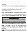
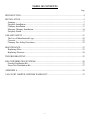
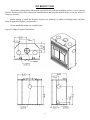
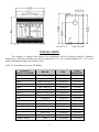
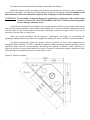
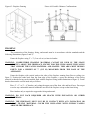
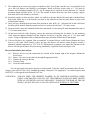
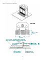
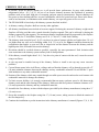
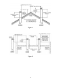
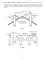
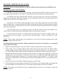
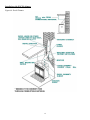
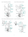
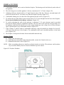
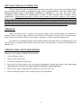
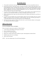
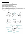
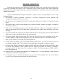
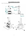
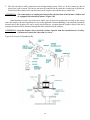
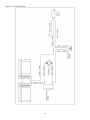
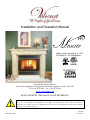
Installation and Operation Manual Safety tested according to ULC S610 and UL 127 Standards by Stove Builder International Inc. 250, rue de Copenhague, St-Augustin-de-Desmoures (Quebec) Canada G3A 2H3 Tel : (418 ) 878-3040 Fax : (418) 878-3001 www.valcourtinc.com READ AND KEEP THIS MANUAL FOR REFERENCE This manual is available for free download on the manufacturer’s web site. It is a copyrighted document. Resale is strictly prohibited. The manufacturer may update this manual from time to time and cannot be responsible for problems, injuries, or damages arising out of the use of information contained in any manual obtained from unauthorized sources. Printed in Canada 45334A 19-03-2012 THANK YOU FOR CHOOSING THIS VALCOURT FIREPLACE As one of North America’s largest and most respected wood stove and fireplace manufacturers, VALCOURT takes pride in the quality and performance of all its products. We want to help you get maximum satisfaction as you use this product. In the pages that follow you will find general advice on wood heating, detailed instructions for safe and effective installation, and guidance on how to get the best performance from this fireplace as you build and maintain fires, and maintain your wood heating system. We recommend that our wood burning hearth products be installed and serviced by professionals who are certified in the United States by NFI (National Fireplace Institute®) or in Canada by WETT (Wood Energy Technical Training) or in Quebec by APC (Association des Professionnels du Chauffage). Congratulations on making a wise purchase. Read this entire manual before you install and use your new fireplace. It is important that you follow the installations guidelines exactly. Failure to install this fireplace correctly could result in a house fire, bodily injury or even death. You may need to obtain a building permit for the installation of this fireplace and the chimney that it is connected to. Consult your municipal building or fire department about installation requirements in your area. We recommend that you also inform your home insurance company to find out if the installation will affect your policy. REGISTER YOU WARRANTY ONLINE To receive full warranty coverage, you will need to show evidence of the date you purchased your unit. Keep your sales invoice. We also recommend that you register your warranty online at http://www.valcourtinc.com/warranty-registration.aspx Registering your warranty online will help us track rapidly the information we need on your unit. PLEASE NOTE THAT THE PICTURES SHOWN IN THIS MANUAL ARE GENERIC AND MAY NOT MATCH EXACTLY THE LOOK OF YOUR FIREPLACE. CAUTION: DO NOT ATTEMPT TO MODIFY OR ALTER THE CONSTRUCTION OF THE FIREPLACE OR ITS COMPONENTS. ANY MODIFICATION OR ALTERATION OF CONSTRUCTION MAY VOID THE WARRANTY, LISTINGS AND APPROVALS OF THIS SYSTEM. IN THAT CASE, STOVE BUILDER INTERNATIONAL (SBI) WILL NOT BE RESPONSIBLE FOR DAMAGES. INSTALL THE FIREPLACE ONLY AS DESCRIBED IN THESE INSTRUCTIONS. WARNING: THE INFORMATION GIVEN ON THE CERTIFICATION LABEL AFFIXED TO THE APPLIANCE ALWAYS OVERRIDES THE INFORMATION PUBLISHED, IN ANY OTHER MEDIA (OWNER’S MANUAL, CATALOGUES, FLYERS, MAGAZINES AND/OR WEB SITES). 2 TABLE OF CONTENTS Page INTRODUCTION .......................................................................................................................... 4 INSTALLATION ........................................................................................................................... 5 Framing ..................................................................................................................................... 7 Fireplace Installation ................................................................................................................. 8 Chimney Installation ............................................................................................................... 11 Masonry Chimney Installation ................................................................................................ 14 Fireplace Finish ....................................................................................................................... 17 USE AND SAFETY..................................................................................................................... 21 The Use of Manufactured Logs............................................................................................... 22 Creosote ................................................................................................................................... 22 Chimney Fire Safety Procedures............................................................................................. 22 MAINTENANCE ......................................................................................................................... 23 Replacing Glass ....................................................................................................................... 23 Replacing Firestone ................................................................................................................. 24 TROUBLESHOOTING ............................................................................................................... 25 HEAT DISTRIBUTION SYSTEMS ........................................................................................... 26 Gravity Distribution Kit .......................................................................................................... 27 Forced Air Distribution Kit ..................................................................................................... 27 APPENDIX A .............................................................................................................................. 30 VALCOURT LIMITED LIFETIME WARRANTY ................................................................... 32 3 INTRODUCTION This manual contains all the information required for safe, efficient installation and use of your Valcourt fireplace. Read carefully all the instructions contained herein and keep this manual handy so you may refer to it whenever necessary. Before starting to install the fireplace, consult local authorities to obtain a builiding permit and learn about all applicable regulatory requirements. Do not install this fireplace in a mobile home. Figure #1: Manoir Fireplace Dimensions 4 INSTALLATION This fireplace is designed and approved for installation with the following brands of chimneys measuring 8” (203 mm) in diameter as well as a minimum of 15’ (4.6 m) and maximum of 45’ (13.7 m) in height including the height of the fireplace itself. Table 1: Listed chimneys for your FP1 Manoir CHIMNEY MANUFACTURER Selkirk Selkirk Selkirk Selkirk Selkirk Selkirk Selkirk Selkirk Selkirk Security Chimney Security Chimney Simpson Dura Vent Simpson Dura Vent ICC Metal Fab Olympia Chimney BRAND TYPE Ultra-Temp (UT) 1” Solid Pack Super Pro (SPR) Super Vent (JSC) Hart & Cooley (TLC) Sure-Temp (ST) CF Sentinel (CF) Super Pro 2100 (ALT) Super Vent 2100 (JM) UltimateOne ASHT+ S-2100 + Dura Tech Dura Plus HTC Excel 2100 Temp Guard Ventis 1” Solid Pack 1” Solid Pack 1” Solid Pack 1” Solid Pack 2” Solid Pack 2” Solid Pack 2” Solid Pack 1” Solid Pack 1” Solid Pack 2” Solid Pack 1” Solid Pack 2” Solid Pack 1” Solid Pack 1” Solid Pack 1” Solid Pack 5 INNER DIAMETER 8" (20 cm) 8" (20 cm) 8" (20 cm) 8" (20 cm) 8" (20 cm) 8" (20 cm) 8" (20 cm) 8" (20 cm) 8" (20 cm) 8" (20 cm) 8" (20 cm) 8" (20 cm) 8" (20 cm) 8" (20 cm) 8" (20 cm) 8" (20 cm) No other device must be added to the chimney connected to the fireplace. Install the fireplace strictly according to the methods described herein and ensure proper clearance is provided to combustibles. Use only the parts and chimneys specified in this manual. Any non-compliance with these directions could create a hazardous situation, thus voiding the certification and the warranty. ATTENTION: Do not modify or adapt the fireplace’s construction or components. This would void the warranty. In this event, VALCOURT FIREPLACES INC. would not be held responsible for any damages which may occur. Choose the best location for your fireplace, based on the position of the doors and windows and room air flow. Provide for the positioning of the outside air inlet (Figure #3) as well as the chimney. Remember to leave sufficient space for the hearth extension and mantel. If possible, install the fireplace where it will not be necessary to cut any floor or ceiling joists. There are several possibilities for the chimney’s configuration. See Figure #4 to determine the appropriate configuration for your home. The straighter the chimney, the easier it will be to clean and maintain. For optimal performance, install the chimney indoors if possible. In areas where temperatures are consistently below freezing (32°F/0ºC), installing the chimney outdoors promotes functional problems such as insufficient draft, excessive creosote buildup, and difficult fire ignition. In addition, outdoor chimneys are subject to decreases in pressure and smoke flow reversal. Fireplaces with outdoor chimneys installed on lower floors (basements) are particularly prone to smoke flow reversal. Figure #2: Fireplace Location 6 Figure #3: Fireplace Framing Figure #4: Possible Chimney Configurations FRAMING The construction of the framing, facing, and mantel must be in accordance with the standards and the following illustrations (figures 2 and 3): Frame the fireplace using 2" × 3" (5 cm x 8 cm) or heavier lumber. WARNING: COMBUSTIBLE FRAMING MATERIAL CANNOT BE USED IN THE SPACE DIRECTLY ABOVE THE FIREPLACE, EXCEPT FOR THE STUDS ABOVE THE FACING THAT SUPPORT THE FACING MATERIAL AND MANTEL. THIS AREA MUST REMAIN EMPTY FOR A HEIGHT OF 7′ (2,15 M) MEASURED FROM THE BASE OF THE APPLIANCE. Frame the fireplace with vertical studs at the sides of the fireplace running from floor to ceiling (see figure 3). Position the studs back from the front edge of the fireplace, a space the thickness of the facing material so that the facing can be installed flush with the fireplace facing (within limitations of figure 3). Frame headers between the vertical studs only as follows: Place 2" × 3" or 2" × 4" headers, only along the upper part of the front, side and back faces. Do not put wood or any combustible material within the area above the fireplace except on the front facing. Place headers only as required to support the facing and mantel. WARNING: DO NOT PACK REQUIRED AIR SPACES WITH INSULATION OR OTHER MATERIALS. WARNING: THE FIREPLACE MUST NOT BE IN CONTACT WITH ANY INSULATION OR LOOSE FILLING MATERIAL. COVER THE INSULATION WITH GYPROC PANELS AROUND THE FIREPLACE. 7 The table below shows the minimum chimney height requirements, fireplace included, according to the number of elbows: Chimney Number of Elbows Minimum Height* Straight installation --------------- 15’ (4.6 m) 1 - 15° offset 2 - 15° elbows 15’ (4.6 m) 2 - 15° offsets 4 - 15° elbows 18’ (5.5 m) 1 - 30° offset 2 - 30° elbows 15’ (4.6 m) 2 - 30° offsets 4 - 30° elbows 20’ (6.1 m) 1 - 45° offset** 2 - 45° elbows** 16’ (4.9 m) 2 - 45° offsets** 4 - 45° elbows** 23’ (7.0 m) * Including the height of the fireplace itself. ** Permitted only in Canada. FIREPLACE INSTALLATION 1. Before beginning installation, remove the fireplace trim to protect it from damage. The fastening screws are located behind the upper and lower louvers. Make sure no masonry products or acids come into contact with the trim as these may discolor the finish which is not under warranty. 2. Remove all combustible floor coverings, e.g. carpeting, linoleum, etc., from the area where the fireplace is to be installed. 3. The fireplace can be installed directly on the floor or on a platform made of combustible materials, such as wood or plywood or any other hard, sturdy surface. 4. A 48” x 16” (1220 mm x 407 mm) minimum hearth extension made of non combustible material is required. The extension can be installed below the base of the fireplace or flush mounted. (Figures #5) 5. To prevent any burning embers falling between the fireplace and the hearth extension from coming into contact with the floor, insert a metal sheet under the front of the fireplace. This sheet must extend 4” (100 mm) on both sides of the fireplace and 2” (50 mm) in front. The non combustible hearth extension should rest on the 2” (50 mm) band of sheet metal in front. You can also prevent embers from falling in the joint between the fireplace and the hearth extension by filling it with mortar grout. (Figure #5) 6. To anchor the fireplace to the floor, unfold the lower metal attachments and screw them to the floor using 1” (25 mm) screws. 7. The opening must be at least 24” (610 mm) away from any wall at a right angle with the appliance’s face. (Figure #12) 8. Place the appliance in the desired location. It must directly abut against the finished wall and not insulation or a vapor barrier. Do not add any insulation. 8 9. The standards in your area may require an outside air inlet. Even if this is not the case, it is beneficial to do so as this will improve the fireplace’s performance. Install a flexible air duct that is 4” (102 mm) in diameter and a maximum length of 20’ (6.1 m). If a longer duct is required, increase diameter to 6” but the maximum length will then be 40’ (12.2 m). The outside air intake must not come from a garage, carport, basement, attic or the chimney’s enclosure. 10. Install the outside air inlet in a place where it is unlikely to become blocked by snow and is sheltered from high winds. Make sure it is far from the gas meter or any other device that may emit fumes or gases, such as automobile exhaust. 11. Once you have decided on the location of the outside air inlet, drill a 4¼” (108 mm) hole in the wall. Insert the inlet grill in the hole from the outside and screw it to the wall with four 1” (25 mm) screws. 12. From the inside, insert the insulated flexible duct and attach it to the inlet grill with aluminum duct tape or ¾” (19 mm) metal screws. 13. On the lower left side of the fireplace, remove the metal piece blocking the air intake. Cut the insulating wool, insert the adaptor included with the fireplace and screw it in place using two ¾” (19 mm) metal screws. Using an adjustable collar or aluminum duct tape, attach the flexible duct to the adaptor. 14. Valcourt fireplaces are equipped with an automatic or manual blower switch located behind the lower louver at your right. When switch is place on auto, the blower will activate when fireplace reaches a minimum starting temperature of 43°C (110°F). When placed on manual, you control the function of the blower with the speed control. Have the wiring installed by a qualified electrician (Figure #19). Electrical Installation Instructions: 14.1 14.2 14.3 14.4 14.5 Remove the cover of the connection box located on the bottom right of the fireplace behind the lower louver. Insert a 110-volt wire into the box through the appropriate hole. Connect the wiring in the box. Test the wiring. Close the connection box. You can also install a decorative gas log set in the hearth. To do this, install an automatic shut-off valve. Comply with ANSI Z21.60 (1991) standards governing “Decorative Gas Appliances” in vented fireplaces and ANSI Z233.1 with regards to the National Gas Code. ATTENTION: ALWAYS OPEN THE CHIMNEY DAMPER TO ITS MAXIMUM POSITION WHEN USING A DECORATIVE GAS LOG SET. THIS FIREPLACE HAS NOT BEEN TESTED WITH AN UNVENTED GAS LOG APPLIANCE. TO REDUCE THE RISK OF FIRE OR INJURY, DO NOT INSTALL A GAS LOG APPLIANCE WITHOUT A VENT PIPE. 9 Figure #5: Hearth Extension Installation 10 CHIMNEY INSTALLATION 1. If possible, install an interior chimney as it will provide better performance. In areas with continuous temperatures below 18 C (0 F), the use of an exterior chimney increases the likelihood of operating problems such as low draft, high rate of creosoting, and poor start-up characteristics. Exterior chimneys are also prone to down-drafting and flow reversal. Installations, which are located on lower floors in the house, such as in a basement, in combination with outside chimney, are especially prone to flow reversal. 2. The FP1 MANOIR is listed only with chimney systems described in table 1. 3. A chimney venting a fireplace shall not vent any other appliance. 4. All chimney installations must include at least one support. Reducing the amount of chimney weight on the fireplace will help avoid the noise created when the fireplace expands. This can be achieved by having the chimney supported by the supports. The maximum chimney length that should be supported by the fireplace is 9 ft. (2.75 m) for 2" Solid Pack Chimney and 12 ft. (3.7 m) for 1" Solid Pack Chimney. 5. The chimney must extend at least 3 ft. (92 cm) above its point of contact with the roof and at least 2 ft. (61 cm) higher than any wall, roof or building within 10 ft. (3.1 m) of it. See Figure A and B to determine the configuration that applies to your roof (flat or sloped roof and the distance between the chimney and the highest point of the roof and/or the nearest chimney). 6. Deviations should be avoided whenever possible, especially the most pronounced. Each deviation adds some restriction to the chimney system and may lead to draft problems. 7. If the chimney extends higher than 5 ft. (1.5 m) above its point of contact with the roof, it must be secured using a roof brace. 8. A rain cap must be installed on top of the chimney. Failure to install a rain cap may cause corrosion problems. 9. Cut and frame square holes in all floors, ceilings, and roof that the chimney will go through to provide a 2" (50 mm) minimum clearance between the chimney and any combustible materials. Do not fill this 2 space with insulation or any other combustible material. 10. Portions of the chimney which may extend through accessible spaces must be enclosed to avoid contact with combustible materials or damage the chimney. 11. To limit creosote buildup, it is strongly recommended that an empty enclosure space be left between the chimney stack and the outer framing of the chimney. Make sure that at all points a minimum clearance of 2” (51 mm) separates the chimney and any combustible materials. 12. Assemble the first chimney section with the adaptor (provided by the chimney manufacturer) using three ¾” (19 mm) screws. 13. Screw this assembly to the fireplace using four ¾” (19 mm) screws, taking care not to block the rotation of the flue damper key. 14. Continue the installation as per the instructions in the chimney manufacturer’s manual (Figures #7, 8, 9, 10). 11 Figure A Figure B 12 15. When you build a chase enclosure for chimney sections above the roof, the chimney must extend at least 3 ft. (92 cm) above the chase enclosure and at least 2 ft. (61 cm) higher than any wall, roof or building within 10 ft. (3.1 m) of it. See Figure C and D to determine the configuration that applies to your roof (flat or sloped roof and the distance between the chimney and the highest point of the roof and/or the nearest chimney). Figure C Figure D 13 MASONRY CHIMNEY INSTALLATION WARNING: Before starting installation, the masonry chimney must be inspected by a qualified sweep. Installation with an 8 in. EXCEL chimney Installing your fireplace with a masonry chimney still requires using EXCEL chimney from the top of the fireplace to the wall where it will connect to a listed liner that will run up inside the masonry chimney. The stainless steel liner should be fitted inside the clay liner all the way to the top of the masonry chimney. It is not meant to replace the clay liner. You can use either the EXCEL liner or any other listed liner or flexible liner to ULC-S635, ULC-S640 or UL777. Special care is to be taken to make sure that you have a good solid connection between the EXCEL chimney and the liner. A masonry adaptor (FO-FDM8) was designed specially for that purpose and is available from your RSF dealer. It will attach to the liner with 3 stainless rivets (provided) and to the EXCEL chimney with 3 screws (provided). After mortaring in place, the connection between the EXCEL chimney and the liner should not be visible in order to isolate the heat released through the liner from the fireplace enclosure. You must install at least one 18” length of EXCEL chimney after the EXCEL chimney elbow. The uppermost part of the excel chimney – where it enters the masonry chimney – must be a minimum of 12” from the ceiling. NOTE: If the ceiling is high enough, you can install one or more EXCEL chimney lengths directly on the fireplace before the elbow. To make the hole through the masonry chimney and make the connection to the fireplace, we recommend that you follow these steps: 1. Sight-in and mark the outline of where the EXCEL chimney will penetrate the masonry chimney. 2. Using a large (3/4”-2”) masonry drill bit, drill a hole exactly in the center of the oval outline. With a masonry hammer and drill, slowly enlarge the hole to the size required. Remember to work from the center out. Be especially careful with the clay liner behind the brick because three sides of it must stay in place. 3. Bring the stainless steel liner down from the top of the chimney. If you are using a rigid liner you will need enough room to secure an elbow to it with at least two screws. If it difficult to install rigid stainless steel liner in the existing masonry chimney or for a masonry chimney with less than 10” x 10” inside, a listed stainless steel flexible liner can be used along with a flexible/ rigid adaptor (LM-7LAF) available from your ICC dealer. 4. Install the liner elbow and masonry adaptor on the lower end of the liner. 5. Move the fireplace forward enough to install the EXCEL chimney on the fireplace (elbow and length) then move the fireplace back into position as you connect the masonry adaptor to the EXCEL chimney. NOTE: The stainless steel flexible liner must be installed inside the clay liner. It is not meant to replace the clay liner. 14 Installation with EXCEL chimney Figure #6: Excel Chimney 15 Figure #7: Straight Chimney Installation Figure #8: Chimney installation with elbows Figure #9: Chimney installation through external wall Figure #10: Chimney in ext. insulated chase 16 FIREPLACE FINISH 1. Combustible materials can be used to finish the fireplace. The framing can be built directly on the sides of the appliance. 2. The side facing can exceed the appliance’s face by a maximum of 6” (152 mm). (Figure #12) 3. Adjoining walls may also be built at a 45 angle from the edge of the face. However, any right angle wall must be located at least 24” (610 mm) away from the fireplace opening. (Figure #12) 4. Combustible framing can cover the sides of the appliance but not its face. (Figure #15) 5. To enclose the top of the finish, it must reach at least 84” (213 cm) in height from the base of the fireplace. Do not insert insulation in the chimney enclosure. (Figure #13) 6. To avoid overheating the walls of the enclosure, a minimum 2” (51 mm) clearance must be provided between the chimney and any combustible materials. The side walls of the enclosure must not angle over the appliance and should be parallel to its sides, rising straight up to the ceiling. Never fill the enclosure space with insulation or any combustible material. (Figures #13) 7. If the 152mm (6”) shelf is made of combustible materials, it must be installed at a height of at least 48” (1220 mm) from the base of the fireplace. The combustible shelf can be installed anywhere in the hatch area. (Figures #14) 8. The fireplace’s facing must be made of non-combustible materials only. Fireplace Facing 8.1 Remove the decorative trim. 8.2 Install the non-combustible facing material (marble, ceramic tile, Durock, brick, etc.). 8.3 Reinstall the decorative trim. (Figure #15) NOTE: Make sure nothing obstructs or interferes with the front hot air outlets. The enclosure could overheat. Any accessible chimney must be chased or finished to prevent contact. Figure #12: Fireplace Finishing 17 Figure #13: Chimney Enclosure 18 Figure #14: Mantel Positioning Figure 14b : Combustible material positioning A : 48 po. B : Radius of 84 in. C : 84 in. Min. 19 Figure #15: Installation of Fireplace Facing Caution: All combustible material may lean directly against all sides of the unit. The non combustible material may lean directly on the front portion of the fireplace and must extend completely that portion. 20 USE AND SAFETY 1. Teach children fireplace safety rules. 2. Do not use the fireplace under the following conditions: 2.1 Whenever a refractory brrick is missing or broken. 2.2 Whenever the ceramic glass is cracked or broken. 3. Never use flammable liquids to light or revive a fire and keep such products away from any heat source. Before lighting a fire, make sure there are no flammable liquids, gases or fumes in the room. 4. Before starting each fire, open the flue damper using the key located in the middle behind the upper louver. When the fireplace is hot, do not touch the damper key with your bare hands. 5. Open the air intake lever located on the left behind the lower louver. 6. Prevent smoke flow reversal by preheating the chimney flue. Just hold a torch made of rolled up newspaper towards the smoke chamber for a few minutes. 7. Valcourt fireplaces are designed to burn reasonable quantities of wood. Avoid making overly intense fires that would damage the appliance. DO NOT OVERHEAT 8. Use the grate made by VALCOURT FIREPLACES INC. Burn only the quantity of combustible it can contain. Do not burn garbage, painted wood or wood that has been exposed to salt water. 9. Always have minimum of 1” accumulation of ash in the bottom of the fireplace. The grate may deform if no ashes are left. 10. When using the fireplace for the first couples of times, make small fires to give the refractory brick time to dry properly. The appearance of fine cracks in the refractory brick is normal and therefore not hazardous. It is not cause for concern. 11. During the first fire, you may detect a certain odor and the coating and oil protecting certain appliance parts may smoke a little. If you open a window, these will quickly dispel. 12. It could also become necessary to open a window if the house is too airtight or if a fan is running. 13. Keep the firescreen closed at all times, you can burn with glass door either closed or open. If the fireplace is left unattended while the fire is still burning, carefully close the glass doors. Adjust the air intake lever to its maximum position. 14. Expansion and contraction noises during the heating and cooling cycle are normal. It is not cause for concern. 15. Once the fire is out and the embers have cooled, close the flue and the air intake dampers until you prepare to light the next fire. NOTE: Make sure furniture, draperies, and any extra logs are a minimum 48” (1220 mm) away from the fireplace. 21 THE USE OF MANUFACTURED LOGS There are numerous types of manufactured logs sold on the market. You must be very careful with this type of product. Many brands of manufactured logs contain chemical additives. DO NOT BURN ANY MANUFACTURED LOGS CONTAINING CHEMICAL ADDITIVES. IF YOU DO, YOU MAY OVERHEAT YOUR FIREPLACE, THEREFORE CAUSING A FIRE HAZARD AND VOIDING YOUR WARRANTY. Manufactured logs made of 100% wood residues do not pose a threat to your fireplace. However, they must be used carefully. Manufactured logs typically release a much larger heat output over a short period of time. Therefore, you cannot place a large quantity of such logs into your fireplace. Start with one log and see how the fireplace reacts. You can increase the number of logs burned at a time to a maximum of three. Burning more than three manufactured logs at one time can overheat and damage your stove. CREOSOTE When wood burns slowly, it produces tar and other organic vapors which combine with humidity to produce creosote. Creosote vapor condenses in the chimney left relatively cool by the slow fire and coats the inside of the flue with residue. When creosote ignites, it produces a red-hot, extremely dangerous fire. It is therefore recommended to make small, brightly burning fires rather than lazy, smoldering fires. Not only will it keep your glass doors and flue cleaner but, what is most important, it will lessen the likelihood of chimney fires. CHIMNEY FIRE SAFETY PROCEDURES What to do if you suspect a chimney fire has started: 1. Close the fireplace doors. 2. Alert everyone in the house. 3. Call the Fire Department if necessary. 4. Put out the fire in the fireplace with a dry-chemical extinguisher, baking soda, sand or ashes. (Never use salt because it is corrosive, nor water because it could cause a steam explosion.) 5. Make sure the sparks coming from the chimney do not set fire to the roof. 6. Before reusing the fireplace, have it inspected by the Fire Department. 22 MAINTENANCE 1. Clean painted or plated trim with soapy water and a soft cloth. Do not use any metal polish or abrasives. 2. Keep the glass relatively clean. Dirty windows will make the fireplace overheat. Wait until the glass is cool before attempting to clean it. Wash the glass with window or oven cleaner, dishwashing liquid or just soap and water. Spray the cleaner on a soft cloth and not on the glass, since overspray may discolor the painted finish or plating (not covered by the warranty). DO NOT use steel wool, soap pads (S.O.S.) or any other abrasive product since these may scratch the glass. 3. To remove the ashes, lift the log support. Put the ashes in a metal container with an airtight lid. Place the container on a non-combustible surface away from any flammables until the ashes are cold. 4. Before each heating season, inspect the interior and exterior of the fireplace and chimney for any defects or deterioration. 5. To reduce the risk of chimney fires, keep the chimney relatively clean and regularly check for creosote buildup. To open the rain cap, just unscrew it counter-clockwise. Any layer of creosote greater than 1/8” (3 mm) thick should be swept. Use a plastic brush to avoid scratching the flue. 6. Lubricate the bearing system on both sides of the box twice a year so the doors continue to work properly. Use a lubricant such as WD-40 or graphite. REPLACING GLASS Do not use the fireplace with a cracked glass. Here are the steps to replace glass windows of a Manoir fireplace: 1. Cut the silicone joint holding the broken glass to the frame. 2. Remove all debris from the frame. 3. Use only 3/16” (5 mm) ceramic glass. 4. Slide the new window into the frame and fasten it in place with temperature-resistant silicone. 5. Handle the glass with care to avoid injury. 6. Allow to dry for 24 hours. NOTE: Never use substitute parts. Use only Valcourt brand parts. 23 REPLACING FIRESTONE Do not use the fireplace with a broken or missing firestone. Here are the steps to replace the refractory brick of a Manoir fireplace: 1. 2. 3. 4. 5. 6. 7. 8. Remove the front refractory brick (VA1-071-5). Unscrew the wall stone attachments (VA1-034). Remove the log support by pulling on it until it comes free. Remove the bottom refractory brick (VA1-071-4). Remove one of the side refractory brick (VA1-71-3 or VA1-071-2). Remove the second side refractory brick while holding the back refractory brick in place (VA1-071-1). Remove the back refractory brick (VA1-071-1). To reinstall the replacement refractory brick, just follow the steps in reverse. Figure #16: Replacing Manoir Firestones 24 TROUBLESHOOTING Expansion and contraction noises during the heating and cooling cycle are normal. Prevent smoke flow reversal by positioning the air intake lever to maximum, slowly open the fireplace doors before lighting the kindling, make a torch by lighting rolled up newspaper and hold it out to the smoke chamber until you feel the chimney begin to draw. A properly installed Manoir Fireplace should never smoke. If it does, it will probably be for one of the following reasons: 1. The chimney’s outdoor installation is defective or incorrect, creating draft reversal problems and, consequently, making it difficult to start a fire. 2. The chimney was not adequately preheated. Remember that the hotter the fireplace, the better the chimney draws. 3. The fireplace doors or the air intake damper were closed too quickly. Adequate air supply is essential to sustaining combustion. 4. If the room is too airtight or negative pressure has built in the house and there is no outside air intake, air supply to the fireplace will be lower than usual. Temporarily open a window near the fireplace to increase air supply. 5. Any type of exhaust fan (range hood or bathroom exhaust fan) can create negative pressure. Shut off the fan and/or open a window near the fireplace to solve this problem. 6. Wet wood smokes more than dry wood. The wetter the wood, the less heat it generates and the more creosote it produces. If the wood being burned is very wet, inspect the chimney every month it is used. 7. Make sure the chimney is reasonably clean and unobstructed. 8. Check whether the chimney is the recommended height: minimum of 3’ (914 mm) from the roof joint. If not, add more lengths of flue. This will improve draw and reduce the fireplace’s tendency to smoke. 9. Fireplaces with chimneys abutting an unfinished outside wall often tend to smoke and are difficult to light. To prevent these problems, open a window near the fireplace and preheat the chimney by holding a newspaper torch in the upper part of the combustion chamber. Wait long enough to establish effective draw, then light the fire. 10. Always remove excess ashes before lighting a fire. Maintaining a 1” (2.5 mm) thickness of ashes optimizes combustion and maximizes fire duration. 11. Use only dry wood, i.e. wood that has dried for one year (15% to 20% humidity). Very dry wood will burn very well, but will generate a great deal of heat and will not last. 25 HEAT DISTRIBUTION SYSTEMS Figure #17: Heat Distribution Options 26 GRAVITY DISTRIBUTION KIT The Gravity Distribution Kit (FP4-300) may be used to heat rooms located above, behind and either side of the room where the fireplace is located. Note that, if the hot air outlets are located at various levels, the heat will tend to seek the one at the highest level. Installing the Gravity Air Duct System 1. Remove the 7” (178 mm) knockouts in the top of the appliance. Cut the insulating wool and remove the inner knockouts. Solidly attach the duct adaptor (FP4-302) to the appliance. 2. Always provide a minimum 2” (51 mm) clearance between the hot air duct and any combustible materials and a 6” (152 mm) clearance between any hot air outlet (FP4-034) and the ceiling. (Figure #17) 3. Direct the gravity heating ducts upward or horizontally. Never direct a duct downward. This system must never be connected to a forced air heating system. If the heating system’s blower were to malfunction, the fireplace enclosure would overheat. Valcourt makes a system specially designed for use with forced air heating systems. (Figure #18) The dimensions recommended for the Gravity Distribution Kit are the following: minimum height of 35” (889 mm) from the base of the fireplace to the centre of the hot air grill and a maximum of 10’ (3 m) from the top of the appliance. The hot air grill must be installed at minimum height of 60” (1.5 m) from the floor of second floor. (Figure #17) WARNING: It is mandatory to install hot air gravity kit when installing cast iron front option. FORCED AIR DISTRIBUTION KIT The Forced Air Distribution Kit can be used to heat adjacent rooms or lower floor located up to 50’ (15.2 m) from your Valcourt Fireplace. Only 6” (15 cm) flexible isolated duct can be use for this installation. (Figures #17 and 18) If the fan is installed with a rheostat, the operation is manually control. The fan can be install with the thermo-disc located under fireplace’s floor, it start automatically when fireplaces floor reach 110°F (43°C). In cooling cycle the fan stops automatically when the fireplace temperature gets under 110°F (43°C). The Forced Air Duct System can be installed in one of two ways 1. Install the flexible duct and connect it to the adaptor attached to one of the fireplace’s two side openings. Install the duct system leading to the adjacent rooms on the lower floors. The fan can be installed anywhere in the house except in the chase. If the fireplace is in a small room, the central fan can be used to draw and redistribute excess heat throughout the house. Be careful where you install the fan, so its noise will not be a nuisance. The length of the duct from the fireplace to the farthest hot air grill must not exceed 50’ (15.2 m). A certain loss of heat is to be expected at this distance. A plastic duct may be connected to the fan’s outlet as long as the duct’s heat resistance is at least 250°F (121°C). Never install a plastic duct in the fireplace enclosure. 27 2. The duct can also be safely connected to an existing heating system. However, do not connect any hot air ducts to the cold air return. The hot air duct must be connected to the main duct coming out of the blower. Install a backflow shutter at the junction between the fireplace duct and the blower outlet duct. ATTENTION: The connection to an existing duct must follow the direction of the furnace’s airflow and be equipped with a backflow shutter. (Figure #18) Both alternatives require electrical power. Make sure all electrical connections are made in the correct order and comply with local regulations as well as the applicable National Building Code standards. Install the rheostat close to the fireplace so it can be easily closed whenever you must open the fireplace doors. If the fan is running, the smoke will be drawn out through the doors instead of up the chimney. ATTENTION: Keep the fireplace fan’s electrical circuitry separate from the central blower’s circuitry. One must not control the other and vice versa. Figure #18: Forced Air Distribution Kit 28 Figure #19: Circuit Diagram 29 APPENDIX A 30 31 VALCOURT LIMITED LIFETIME WARRANTY The warranty of the manufacturer extends only to the original consumer purchaser and is not transferable. This warranty covers brand new products only, which have not been altered, modified nor repaired since shipment from factory. Products covered under this warranty must have been manufactured after the revision date indicated below. Proof of purchase (dated bill of sale), model name and serial number must be supplied when making any warranty claim to your VALCOURT dealer. This warranty applies to normal residential use only. Damages caused by misuse, abuse, improper installation, lack of maintenance, over firing, negligence or accident during transportation, power failures, downdrafts, or venting problems are not covered by this warranty. This warranty does not cover any scratch, corrosion, distortion, or discoloration. Any defect or damage caused by the use of unauthorized parts or others than original parts void this warranty. An authorized qualified technician must perform the installation in accordance with the instructions supplied with this product and all local and national building codes. Any service call related to an improper installation is not covered by this warranty. The manufacturer may require that defective products be returned or that digital pictures be provided to support the claim. Returned products are to be shipped prepaid to the manufacturer for investigation. If a product is found to be defective, the manufacturer will repair or replace such defect. Transportation fees to ship the product back to the purchaser will be paid by the manufacturer. Repair work covered by the warranty, executed at the purchaser’s domicile by an authorized qualified technician requires the prior approval of the manufacturer. Labour cost and repair work to the account of the manufacturer are based on predetermined rate schedule and must not exceed the wholesale price of the replacement part. All parts and labour costs covered by this warranty are limited according to the table below. The manufacturer at its discretion may decide to repair or replace any part or unit after inspection and investigation of the defect. The manufacturer may, at its discretion, fully discharge all obligations with respect to this warranty by refunding the wholesale price of any warranted but defective parts. The manufacturer shall in no event be responsible for any special, indirect, consequential damages of any nature, which are in excess of the original purchase price of the product. A one-time replacement limit applies to all parts benefiting from a lifetime coverage. This warranty applies to products purchased after October 1st, 2011. WARRANTY APPLICATION PARTS LABOUR DESCRIPTION Combustion chamber (welds only), castings, convector air-mate, ceramic glass (thermal breakage only*), and secondary air tubes*. Plating* (defective manufacture) – subject to limitations above. Stainless steel firebox components, surrounds and heat shields, ash drawer, steel legs, pedestal, trims (aluminum extrusions), C-Cast baffle*, and vermiculite baffle*. Carbon steel firebox components, glass retainers, and handle assembly. Blowers, heat sensors, switches, rheostat, wiring, and other controls. Paint (peeling), gaskets, insulation, firebrick, and ceramic fibre blankets. *Pictures required Lifetime 4 years Lifetime n/a 5 years 3 years 3 years 2 years 1 year 2 years 1 year n/a Shall your unit or a components be defective, contact immediately your VALCOURT dealer. Prior to your call make sure you have the following information necessary to your warranty claim treatment: Your name, address and telephone number; Bill of sale and dealer’s name; Serial number and model name as indicated on the nameplate fixed to the back of your unit; Nature of the defect and any relevant information. Before shipping your unit or defective component to our plant, you must obtain from your VALCOURT dealer an Authorization Number. Any merchandise shipped to our plant without authorization will be refused automatically and returned to sender. 32