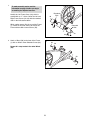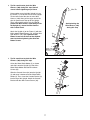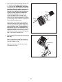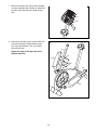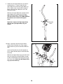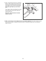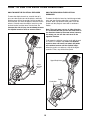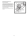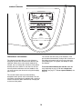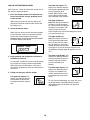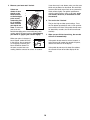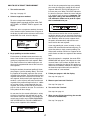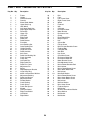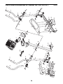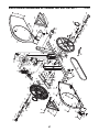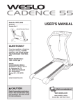
1
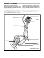
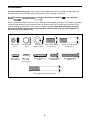
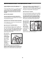
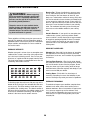
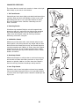
Model No. 831.23743.1
Serial No.
Write the serial number in the
space above for reference.
ELLIPTICAL EXERCISER
Userʼs Manual
Serial
Number
Decal
• Assembly
• Operation
• Maintenance
• Part List and Drawing
CAUTION
Read all precautions and instructions in this manual before using
this equipment. Keep this manual
for future reference.
Sears, Roebuck and Co., Hoffman Estates, IL 60179
TABLE OF CONTENTS
WARNING DECAL PLACEMENT . . . . . . . . . . . . . . . . . . . . . . . . . . . . . . . . . . . . . . . . . . . . . . . . . . . . . . . . . . . . . .2
IMPORTANT PRECAUTIONS . . . . . . . . . . . . . . . . . . . . . . . . . . . . . . . . . . . . . . . . . . . . . . . . . . . . . . . . . . . . . . . .3
BEFORE YOU BEGIN . . . . . . . . . . . . . . . . . . . . . . . . . . . . . . . . . . . . . . . . . . . . . . . . . . . . . . . . . . . . . . . . . . . . . .4
ASSEMBLY . . . . . . . . . . . . . . . . . . . . . . . . . . . . . . . . . . . . . . . . . . . . . . . . . . . . . . . . . . . . . . . . . . . . . . . . . . . . . . .5
HOW TO USE THE ELLIPTICAL EXERCISER . . . . . . . . . . . . . . . . . . . . . . . . . . . . . . . . . . . . . . . . . . . . . . . . . .12
MAINTENANCE AND TROUBLESHOOTING . . . . . . . . . . . . . . . . . . . . . . . . . . . . . . . . . . . . . . . . . . . . . . . . . . .19
EXERCISE GUIDELINES . . . . . . . . . . . . . . . . . . . . . . . . . . . . . . . . . . . . . . . . . . . . . . . . . . . . . . . . . . . . . . . . . . .20
PART LIST . . . . . . . . . . . . . . . . . . . . . . . . . . . . . . . . . . . . . . . . . . . . . . . . . . . . . . . . . . . . . . . . . . . . . . . . . . . . . .24
EXPLODED DRAWING . . . . . . . . . . . . . . . . . . . . . . . . . . . . . . . . . . . . . . . . . . . . . . . . . . . . . . . . . . . . . . . . . . . .26
ORDERING REPLACEMENT PARTS . . . . . . . . . . . . . . . . . . . . . . . . . . . . . . . . . . . . . . . . . . . . . . . . . .Back Cover
90 DAY FULL WARRANTY . . . . . . . . . . . . . . . . . . . . . . . . . . . . . . . . . . . . . . . . . . . . . . . . . . . . . . . . . .Back Cover
WARNING DECAL PLACEMENT
This drawing shows the location(s) of the
warning decal(s). If a decal is missing or
illegible, call 1-888-533-1333 and
request a free replacement decal.
Apply the decal in the location shown.
Note: The decal(s) may not be shown at
actual size.
2
IMPORTANT PRECAUTIONS
WARNING:
To reduce the risk of serious injury, read all important precautions and
instructions in this manual and all warnings on your elliptical exerciser before using your elliptical
exerciser. Sears assumes no responsibility for personal injury or property damage sustained by or
through the use of this product.
8. Wear appropriate exercise clothes when
exercising; do not wear loose clothes that
could become caught on your elliptical exerciser. Always wear athletic shoes for foot
protection.
1. Before beginning any exercise program,
consult your physician. This is especially
important for persons over the age of 35 or
persons with pre-existing health problems.
2. It is the responsibility of the owner to ensure
that all users of the elliptical exerciser are
adequately informed of all precautions.
9. Hold the handgrip pulse sensor or the upper
body arms when mounting, dismounting, or
using your elliptical exerciser.
3. Your elliptical exerciser is intended for home
use only. Do not use your elliptical exerciser
in a commercial, rental, or institutional setting.
10. Keep your back straight while using your
elliptical exerciser; do not arch your back.
11. The pulse sensor is not a medical device.
Various factors, including the userʼs movement, may affect the accuracy of heart rate
readings. The pulse sensor is intended only
as an exercise aid in determining heart rate
trends in general.
4. Keep your elliptical exerciser indoors, away
from moisture and dust. Place your elliptical
exerciser on a level surface, with a mat
beneath it to protect the floor or carpet.
Make sure that there is enough clearance
around your elliptical exerciser to mount,
dismount, and use it.
12. When you stop exercising, allow the pedals
to slowly come to a stop.
5. Inspect and properly tighten all parts regularly. Replace any worn parts immediately.
13. If you feel pain or dizziness while exercising,
stop immediately and cool down.
6. Keep children under age 12 and pets away
from your elliptical exerciser at all times.
14. Use your elliptical exerciser only as
described in this manual.
7. Your elliptical exerciser should not be used
by persons weighing more than 250 lbs.
(113 kg).
3
BEFORE YOU BEGIN
cover of this manual. To help us assist you, note the
product model number and serial number before contacting us. The model number and the location of the
serial number decal are shown on the front cover of
this manual.
Thank you for purchasing the revolutionary
PROFORM® XP 420 Razor elliptical exerciser. The XP
420 Razor elliptical exerciser provides a wide array of
features designed to make your workouts at home
more effective and enjoyable.
For your benefit, read this manual carefully before
you use the elliptical exerciser. If you have questions after reading this manual, please see the back
Before reading further, please familiarize yourself with
the parts that are labeled in the drawing below.
Fan
Upper Body Arm
Console
Pulse Sensor
Water Bottle Holder*
Wheel
Pedal Disc
Pedal
Adjustment Knob
*No water bottle is included
4
ASSEMBLY
Assembly requires two persons. Place all parts of the elliptical exerciser in a cleared area and remove the
packing materials. Do not dispose of the packing materials until assembly is completed.
Assembly requires the included hex keys and your own Phillips screwdriver
wrench
, and rubber mallet
.
, adjustable
As you assemble the elliptical exerciser, use the drawings below to identify small parts. The number in parentheses below each drawing is the key number of the part, from the PART LIST near the end of this manual. The
number following the parentheses is the quantity needed for assembly. Note: Some small parts may have
been preassembled. If a part is not in the hardware kit, check to see if it has been preassembled. If a
part is missing, call 1-888-533-1333.
M6 Locknut
(77)–4
M4 x 16mm
Screw (84)–12
Wave Washer
(88)–2
M4 x 16mm
Flat Head
Screw (94)–4
M10 Split
Washer (78)–10
M10 x 20mm Button
Screw (79)–4
M4 x 32mm Screw
(95)–2
M6 x 16mm Button
Screw (80)–6
M10 x 70mm Button Screw (75)–6
5
M10 x 41mm Shoulder
Screw (63)–2
M6 x 38mm Button
Bolt (76)–4
1.
1
To make assembly easier, read the
information on page 5 before you begin
assembling the elliptical exerciser.
Identify the Left Frame Cover (48), which is
marked with an “L” sticker. Orient the Left and
Right Frame Covers (48, 49) with the rounded
sides in the indicated locations.
48
While another person lifts the rear of the Frame
(1), attach each Frame Cover (48, 49) to the
Frame with two M4 x 16mm Screws (84).
Rounded
Side
84
2. Attach a Wheel (50) to the front of the Frame
(1) with an M10 x 41mm Shoulder Screw (63).
2
Repeat this step to attach the other Wheel
(50).
63
1
Rounded
Side
49
84
50
1
50
63
6
3. Tip: Be careful not to pinch the Wire
Harness (100) during this step. Start all
screws before tightening any of them.
3
Wire Tie
Have another person hold the Upright (2) near
the Frame (1). Locate the wire tie in the Upright.
Tie the lower end of the wire tie to the Wire
Harness (100). Next, pull the upper end of the
wire tie upward out of the top of the Upright.
Then, untie and discard the wire tie. Tip: To
prevent the Wire Harness from falling inside
the Upright (2), secure the Wire Harness
with a rubber band.
Avoid pinching the
Wire Harness (100)
during this step
2
Attach the Upright (2) to the Frame (1) with four
M10 x 20mm Button Screws (79), and four M10
Split Washers (78). Tip: Tighten the two
Button Screws on the front of the elliptical
exerciser before tightening the other two
Button Screws.
79
78
78
78
100
79
1
4. Tip: Be careful not to pinch the Wire
Harness (100) during this step.
4
Orient the Water Bottle Holder (5) as shown
and slide it onto the Upright (2). Attach the
Water Bottle Holder with two M4 x 32mm
Screws (95).
79
3
100
96
84
Slide the Console Cover (96) onto the Upright
(2) and move it downward to the Water Bottle
Holder (5). Then, insert the Console Bracket (3)
into the top of the Upright. Attach the Console
Bracket with four M4 x 16mm Screws (84).
5
7
2
84
95
5. The Console (4) can be operated with four 1.5V
“D” batteries (not included); alkaline batteries
are recommended. IMPORTANT: If the elliptical exerciser has been exposed to cold temperatures, allow it to warm to room temperature before inserting batteries into the
Console. If you do not do this, the console
displays or other electronic components
may become damaged. Remove the two
screws from the back of the console, and
remove the battery cover. Insert four batteries
into the Console. Orient the batteries as shown
by the markings inside the battery compartment.
Then, reattach the battery cover.
5
Cover
Screws
The Console (4) can also be operated with a
regulated 6-volt DC 2-amp power supply (not
included). To purchase a power supply, call
your local Sears store. To avoid damaging
the console, use only a manufacturer-supplied power supply. Plug one end of the power
supply into the jack on the Console; plug the
other end into an outlet installed in accordance
with all local codes and ordinances.
6. Tip: Be careful not to pinch the wires during
this step.
4
Batteries
6
While a second person holds the Console (4)
near the Upright (2), connect the console wire
to the Wire Harness (100).
4
Console Wire
Attach the Console (4) with four M4 x 16mm
Flat Head Screws (94).
100
96
8
2
94
94
7. Slide the Console Cover (96) (see the drawing
in step 6) upward to the Console (4). Attach the
Console Cover with two M4 x 16mm Screws
(84).
7
4
96
84
8. Attach the Left Pedal (12) to the left Pedal Arm
(14) with three M10 x 70mm Button Screws
(75), three Split Washers (78), and an M4 x
16mm Screw (84).
8
14
Repeat this step on the right side of the
elliptical exerciser.
78
12
84
78
75
14
13
9
9. Identify the Left Upper Body Arm (8), which is
marked with an “L” sticker. Orient the Left
Upper Body Arm and the left Upper Body Leg
(6) as shown; make sure that the hexagonal
holes in the Left Upper Body Arm are in the
indicated location.
9
8
Slide the Left Upper Body Arm (8) onto the left
Upper Body Leg (6). Attach the Left Upper
Body Arm with two M6 x 38mm Button Bolts
(76) and two M6 Locknuts (77); make sure that
the Locknuts are inside the hexagonal
holes.
77
76
Repeat this step for the Right Upper Body
Arm and the right Upper Body Leg (not
shown).
Hexagonal
Holes
6
10. Apply a generous amount of the included
grease to the Pivot Axle (16). Then, apply a
small amount of grease to two Wave Washers
(88).
10
Insert the Pivot Axle (16) into the Upright (2).
Place a Wave Washer (88) on each end of the
Pivot Axle.
80
Slide the left Upper Body Leg (6) onto the Pivot
Axle (16). Attach the left Upper Body Leg with
an M6 x 16mm Button Screw (80) and a Large
Axle Cover (20). Attach the right Upper Body
Leg (6) in the same way.
20
6
2
88
Grease
10
16
88
20
6
80
11. Apply a small amount of grease to a Pedal Arm
Axle (21). While another person holds the right
Pedal Arm (14) inside the bracket on the right
Upper Body Leg (6), insert the Pedal Arm Axle
through the Upper Body Leg and the Pedal
Arm.
11
14
6
80
22
Then, tighten an M6 x 16mm Button Screw (80)
and an Axle Cover (22) into each end of the
Pedal Arm Axle (21).
Repeat this step for the other side of the
elliptical exerciser.
6
Grease
21
14
22
80
12. Make sure that all parts of the elliptical exerciser are properly tightened. Note: Some hardware may be
left over after assembly is completed. To protect the floor or carpet from damage, place a mat under the
elliptical exerciser.
11
HOW TO USE THE ELLIPTICAL EXERCISER
HOW TO EXERCISE ON THE ELLIPTICAL
EXERCISER
HOW TO MOVE THE ELLIPTICAL EXERCISER
To move the elliptical exerciser, stand in front of it,
place one foot against one of the wheels, and firmly
hold the upper end of the upright. Pull the upright forward until you can move the elliptical exerciser on the
wheels. Carefully move the elliptical exerciser to the
desired location and then lower it to the floor. To
decrease the risk of injury, do not attempt to move
the elliptical exerciser over an uneven surface.
To mount the elliptical exerciser, hold the upper body
arms and step onto the pedal that is in the lowest
position. Next, step onto the other pedal. Push the
pedals until they begin to move with a continuous
motion.
Note: The crank arms can turn in either direction.
It is recommended that you turn the crank arms in
the direction shown by the arrow below; however,
for variety you can turn the crank arms in the
opposite direction.
To dismount the elliptical exerciser, wait until the pedals come to a complete stop. Note: The elliptical
exerciser does not have a free wheel; the pedals
will continue to move until the flywheel stops.
When the pedals are stationary, step off the higher
pedal first. Then, step off the lower pedal.
Upright
Upper Body Arms
Place
your foot
here
Wheel
Crank Arm
12
Pedals
HOW TO ADJUST THE STRIDE OF THE
ELLIPTICAL EXERCISER
Crank
Arm
To adjust the stride of the elliptical exerciser, first pull
one of the adjustment knobs until the adjustment
bracket pivots freely. Pivot the adjustment bracket until
the adjustment knob is aligned with one of the holes in
the crank arm, and gently release the knob. Then,
pivot the adjustment bracket back and forth slightly to
make sure that the adjustment pin is engaged in one
of the holes in the crank arm.
Holes
Adjust the other side of the elliptical exerciser in the
same way.
Adjustment
Pin
13
Adjustment
Bracket
Adjustment
Knob
CONSOLE DIAGRAM
FEATURES OF THE CONSOLE
The console also offers four preset workouts. Each
preset workout automatically changes the resistance of
the pedals and prompts you to increase or decrease
your pedaling pace as it guides you through an effective workout.
The advanced console offers an array of features
designed to make your workouts more effective and
enjoyable. When you use the manual mode of the
console, you can change the resistance of the pedals
with the touch of a button. As you exercise, the console will provide continuous exercise feedback. You
can even measure your heart rate using the handgrip
pulse sensor.
To use the manual mode of the console, follow the
steps beginning on page 15. To use a target tone
workout, see page 17. To use a preset workout, see
page 18.
The console features two target tone workouts
designed to work specific areas of the body. The console guides you through each workout with a variety of
exercise instructions while automatically changing the
resistance of the pedals.
14
HOW TO USE THE MANUAL MODE
The lower left display–This
display can show the elapsed
time and the approximate number of calories you have
burned. Note: During a workout, the display will show the
time remaining in the workout.
Note: If there is a sheet of clear plastic on the face of
the console, remove the plastic.
1. Press the Display button or the decrease button on the console, or begin pedaling to turn
on the console.
The upper middle display–This display will show the
resistance level of the pedals
for a few seconds each time the
resistance level changes. This
display will also show your
heart rate when you use the handgrip pulse sensor
(see step 5 on page 16).
When you turn on the console, the display will
light. A tone will then sound and the console will
be ready for use.
2. Select the manual mode.
When you turn on the console, the manual mode
will be selected. If you have selected a workout,
reselect the manual mode by pressing the
Workouts button repeatedly until the words MANUAL MODE appear in the display.
The lower middle display–This display will show a
track representing 640 revolutions. As you exercise, indicaTrack
tors will appear in succession
around the track until the entire
track appears. The track will then disappear and
the indicators will again begin to appear in succession.
The upper right display–This
display can show the distance
you have pedaled (in total revolutions) and your pedaling
pace (in revolutions per
minute).
3. Begin pedaling and change the resistance of
the pedals as desired.
As you pedal, change the resistance of the pedals
by pressing the increase and decrease buttons.
Note: After you press the buttons, it will take a
moment for the pedals to reach the selected resistance level.
The lower right display–This
display can show your pedaling pace (in revolutions per
minute) and the distance you
have pedaled (in total revolutions).
4. Follow your progress with the display.
The upper left display–This
display can show the approximate number of calories you
have burned and the elapsed
time.
To view selected information at a larger size, press
the Display button repeatedly until the desired
information appears in the lower left and lower
right displays.
15
5. Measure your heart rate if desired.
If your heart rate is not shown, make sure that your
hands are positioned as described. Be careful not
to move your hands excessively or to squeeze the
metal contacts tightly. For optimal performance,
clean the metal contacts using a soft cloth; never
use alcohol, abrasives, or chemicals to clean
the contacts.
If there are
sheets of clear
Contacts
plastic on the
metal contacts
on the handgrip
pulse sensor,
remove the plastic. In addition,
make sure that
your hands are
clean. To measure
your heart rate,
hold the handgrip pulse sensor with your palms
resting against the metal contacts. Avoid moving
your hands or gripping the contacts tightly.
6. Turn on the fan if desired.
The fan has high and low speed settings. Press
the Fan button repeatedly to select a fan speed or
to turn off the fan. Note: If the pedals do not move
for about thirty seconds, the fan will turn off automatically.
7. When you are finished exercising, the console
will turn off automatically.
When your pulse is detected, a
heart-shaped symbol will flash
in the display, one or two dashes will appear, and then your
heart rate will be shown. For
the most accurate heart rate
reading, hold the contacts for at least 15 seconds.
If the pedals do not move for several seconds, a
series of tones will sound, the console will pause,
and the time will flash in the display.
If the pedals do not move for about five minutes,
the console will turn off and the display will be
reset.
16
HOW TO USE A TARGET TONE WORKOUT
You will also be prompted to keep your pedaling
pace near the target pace setting for the current
segment. When the TOO SLOW indicator is lit,
increase your pace. When TOO FAST indicator is
lit, decrease your pace. When the center indicator
is lit, maintain your current pace. Important: The
target pace settings are intended only to provide motivation. Make sure to pedal at a pace
that is comfortable for you.
1. Turn on the console.
See step 1 on page 15.
2. Select a target tone workout.
To select a target tone workout, press the
Workouts button repeatedly until the words TARGET TONE 1 or TARGET TONE 2 appear in the
display.
When you select a target tone workout, the name
of the workout and the workout time will appear in
the display. A profile of the resistance levels of the
workout will also scroll across the display.
If the resistance level for the current segment is
too high or too low, you can manually override the
setting by pressing the decrease and increase buttons. However, when the current segment ends,
the pedals will automatically adjust to the resistance level for the next segment.
If you stop pedaling for several seconds, a series
of tones will sound and the workout will pause. To
restart the workout, simply resume pedaling. The
workout will continue until the last segment of the
profile flashes and the last segment of the workout
ends.
Profile
3. Begin pedaling to start the workout.
Each workout is divided into 30 one-minute segments. One resistance level and one target pace
setting are programmed for each segment. Note:
The same resistance level and/or target pace setting may be programmed for two or more consecutive segments.
When the workout is completed, the words PROGRAM DONE will appear in the display for a few
seconds. Note: If you continue to pedal after the
workout is completed, the display will continue to
show exercise feedback; however, the display will
not show the elapsed time until you select the
manual mode or a new workout.
During the workout, the workout profile will show
your progress (see the drawing above). The flashing segment of the profile represents the current
segment of the workout. The height of the flashing
segment indicates the resistance level for the current segment. At the end of each segment of the
workout, a series of tones will sound and the next
segment of the profile will begin to flash. If a different resistance level is programmed for the next
segment, the resistance level will flash in the display for a few seconds to alert you. The resistance
of the pedals will then change.
4. Follow your progress with the display.
See step 4 on page 15.
5. Measure your heart rate if desired.
See step 5 on page 16.
6. Turn on the fan if desired.
See step 6 on page 16.
As you exercise, the console will display a variety
of exercise instructions that will help you get the
most benefit from your workout. For example, the
console may instruct you to PEDAL BACKWARD,
USE UPPER BODY, or FOCUS LOWER BODY
during certain segments of the workout.
7. When you are finished exercising, the console
will turn off automatically.
See step 7 on page 16.
17
HOW TO USE A PRESET WORKOUT
lit, decrease your pace. When the center indicator
is lit, maintain your current pace. Important: The
target pace settings are intended only to provide motivation. Make sure to pedal at a pace
that is comfortable for you.
1. Turn on the console.
See step 1 on page 15.
2. Select a preset workout.
To select a preset workout, press the Workouts
button repeatedly until the name of the desired
workout appears in the display.
If the resistance level for the current segment is
too high or too low, you can manually override the
setting by pressing the decrease and increase buttons. However, when the current segment ends,
the pedals will automatically adjust to the resistance level for the next segment.
When you select a preset workout, the name of
the workout will appear in the display and a profile
of the resistance levels of the workout will scroll
across the matrix.
If you stop pedaling for several seconds, a series
of tones will sound and the workout will pause. To
restart the workout, simply resume pedaling. The
workout will continue until the last segment of the
profile flashes and the last segment of the workout
ends.
Profile
3. Begin pedaling to start the workout.
When the workout is completed, the words PROGRAM DONE will appear in the display for a few
seconds. Note: If you continue to pedal after the
workout is completed, the display will continue to
show exercise feedback; however, the display will
not show the elapsed time until you select the
manual mode or a new workout.
Each workout is divided into 20, 30, or 45 oneminute segments. One resistance level and one
target pace setting are programmed for each segment. Note: The same resistance level and/or target
pace setting may be programmed for two or more
consecutive segments.
4. Follow your progress with the display.
During the workout, the workout profile will show
your progress (see the drawing above). The flashing segment of the profile represents the current
segment of the workout. The height of the flashing
segment indicates the resistance level for the current segment. At the end of each segment of the
workout, a series of tones will sound and the next
segment of the profile will begin to flash. If a different resistance level is programmed for the next
segment, the resistance level will flash in the display for a few seconds to alert you. The resistance
of the pedals will then change.
See step 4 on page 15.
5. Measure your heart rate if desired.
See step 5 on page 16.
6. Turn on the fan if desired.
See step 6 on page 16.
7. When you are finished exercising, the console
will turn off automatically.
You will also be prompted to keep your pedaling
pace near the target pace setting for the current
segment. When the TOO SLOW indicator is lit,
increase your pace. When TOO FAST indicator is
See step 7 on page 16.
18
MAINTENANCE AND TROUBLESHOOTING
Inspect and tighten all parts of the elliptical exerciser
regularly. Replace any worn parts immediately.
until the console displays correct feedback. When the
Reed Switch is correctly adjusted, reattach the
shields. Note: If you have questions as to which screw
should be in which hole, see EXPLODED DRAWING
B on page 27 and the PART LIST on page 24.
To clean the elliptical exerciser, use a damp cloth and
a small amount of mild soap. Important: To avoid
damage to the console, keep liquids away from
the console and keep the console out of direct
sunlight.
HOW TO ADJUST THE BELT
If you can feel the pedals slip while you are pedaling,
even when the resistance of the pedals is at the highest setting, the Belt (46) may need to be adjusted.
First, remove all the screws from both shields; there
are three sizes of screws in the shields—note
which size of screw you remove from each hole.
Then, gently pry the shields away from the frame.
BATTERY REPLACEMENT
If the console displays become dim, the batteries
should be replaced; most console problems are the
result of low batteries. See assembly step 5 on page 8
for replacement instructions.
HANDGRIP PULSE SENSOR TROUBLESHOOTING
Next, turn the Belt
Adjustment Screw
(72) until the Belt
(46) is tight. Then,
reattach the
shields. Note: If
you have questions as to which
screw should be
in which hole, see
72
EXPLODED
DRAWING B on
page 27 and the PART LIST on page 24.
If the handgrip pulse sensor does not function properly, see step 5 on page 16.
HOW TO ADJUST THE REED SWITCH
If the console does not display correct feedback, the
reed switch should be adjusted. First, remove all of
the screws from both shields; there are three sizes of
screws in the shields—note which size of screw
you remove from each hole. Then, gently pry the
shields away from the frame.
Next, locate the
Reed Switch (58).
Turn the Left
41 26
58
Pedal Disc (26)
84
until the Magnet
(41) is aligned
with the Reed
Switch. Loosen,
but do not
remove, the indicated M4 x
16mm Screw
(84). Slide the
Reed Switch slightly closer to or away from the
Magnet, and then retighten the Screw. Rock the Left
Pedal Disc forward and backward just enough that the
Magnet passes the Reed Switch repeatedly. Repeat
19
46
EXERCISE GUIDELINES
WARNING:
Burning Fat—To burn fat effectively, you must exercise at a low intensity level for a sustained period of
time. During the first few minutes of exercise, your
body uses carbohydrate calories for energy. Only after
the first few minutes of exercise does your body begin
to use stored fat calories for energy. If your goal is to
burn fat, adjust the intensity of your exercise until your
heart rate is near the lowest number in your training
zone. For maximum fat burning, exercise with your
heart rate near the middle number in your training
zone.
Before beginning
this or any exercise program, consult your
physician. This is especially important for
persons over the age of 35 or persons with
pre-existing health problems.
The pulse sensor is not a medical device.
Various factors may affect the accuracy of
heart rate readings. The pulse sensor is
intended only as an exercise aid in determining heart rate trends in general.
Aerobic Exercise—If your goal is to strengthen your
cardiovascular system, you must perform aerobic
exercise, which is activity that requires large amounts
of oxygen for prolonged periods of time. For aerobic
exercise, adjust the intensity of your exercise until
your heart rate is near the highest number in your
training zone.
These guidelines will help you to plan your exercise
program. For detailed exercise information, obtain a
reputable book or consult your physician. Remember,
proper nutrition and adequate rest are essential for
successful results.
WORKOUT GUIDELINES
EXERCISE INTENSITY
Warming Up—Start with 5 to 10 minutes of stretching
and light exercise. A warm-up increases your body
temperature, heart rate, and circulation in preparation
for exercise.
Whether your goal is to burn fat or to strengthen your
cardiovascular system, exercising at the proper intensity is the key to achieving results. You can use your
heart rate as a guide to find the proper intensity level.
The chart below shows recommended heart rates for
fat burning and aerobic exercise.
Training Zone Exercise—Exercise for 20 to 30 minutes with your heart rate in your training zone. (During
the first few weeks of your exercise program, do not
keep your heart rate in your training zone for longer
than 20 minutes.) Breathe regularly and deeply as you
exercise–never hold your breath.
Cooling Down—Finish with 5 to 10 minutes of
stretching. Stretching increases the flexibility of your
muscles and helps to prevent post-exercise problems.
EXERCISE FREQUENCY
To find the proper intensity level, find your age at the
bottom of the chart (ages are rounded off to the nearest ten years). The three numbers listed above your
age define your “training zone.” The lowest number is
the heart rate for fat burning, the middle number is the
heart rate for maximum fat burning, and the highest
number is the heart rate for aerobic exercise.
To maintain or improve your condition, complete three
workouts each week, with at least one day of rest
between workouts. After a few months of regular exercise, you may complete up to five workouts each
week, if desired. Remember, the key to success is to
make exercise a regular and enjoyable part of your
everyday life.
20
SUGGESTED STRETCHES
The correct form for several basic stretches is shown at the right.
Move slowly as you stretch—never bounce.
1
1. Toe Touch Stretch
Stand with your knees bent slightly and slowly bend forward from
your hips. Allow your back and shoulders to relax as you reach
down toward your toes as far as possible. Hold for 15 counts,
then relax. Repeat 3 times. Stretches: Hamstrings, back of
knees, and back.
2
2. Hamstring Stretch
Sit with one leg extended. Bring the sole of the opposite foot
toward you and rest it against the inner thigh of your extended
leg. Reach toward your toes as far as possible. Hold for 15
counts, then relax. Repeat 3 times for each leg. Stretches:
Hamstrings, lower back, and groin.
3. Calf/Achilles Stretch
With one leg in front of the other, reach forward and place your
hands against a wall. Keep your back leg straight and your back
foot flat on the floor. Bend your front leg, lean forward and move
your hips toward the wall. Hold for 15 counts, then relax. Repeat
3 times for each leg. To cause further stretching of the achilles
tendons, bend your back leg as well. Stretches: Calves, achilles
tendons, and ankles.
3
4
4. Quadriceps Stretch
With one hand against a wall for balance, reach back and grasp
one foot with your other hand. Bring your heel as close to your
buttocks as possible. Hold for 15 counts, then relax. Repeat 3
times for each leg. Stretches: Quadriceps and hip muscles.
5. Inner Thigh Stretch
Sit with the soles of your feet together and your knees outward.
Pull your feet toward your groin area as far as possible. Hold for
15 counts, then relax. Repeat 3 times. Stretches: Quadriceps and
hip muscles.
21
5
NOTES
22
NOTES
23
PART LIST—Model No. 831.23743.1
Key No. Qty.
1
2
3
4
5
6
7
8
9
10
11
12
13
14
15
16
17
18
19
20
21
22
23
24
25
26
27
28
29
30
31
32
33
34
35
36
37
38
39
40
41
42
43
44
45
1
1
1
1
1
2
1
1
1
2
2
1
1
2
2
1
2
2
2
2
2
4
4
1
1
1
1
2
2
2
1
4
2
4
2
2
2
2
1
1
2
1
1
1
1
Description
Frame
Upright
Console Bracket
Console
Water Bottle Holder
Upper Body Leg
Idler Wheel
Left Upper Body Arm
Right Upper Body Arm
Foam Grip
Upper Cap
Left Pedal
Right Pedal
Pedal Arm
Pedal Bracket
Pivot Axle
Inner Bushing Set
Outer Bushing Set
Upright Bushing
Large Axle Cover
Pedal Arm Axle
Axle Cover
Pedal Arm Bushing Set
Crank Assembly
Crank Arm
Left Pedal Disc
Right Pedal Disc
Pedal Disc Cover
Adjustment Pin
Spring
Right Adjustment Bracket
Large Snap Ring
39mm x 31mm Wave Washer
Adjustment Bushing
Pedal Arm Bracket
Adjustment Knob
Fender Washer
Crank Bearing
Crank Spacer
Crank Arm Spacer
Magnet
Left Front Shield
Right Front Shield
Left Shield
Right Shield
Key No. Qty.
46
47
48
49
50
51
52
53
54
55
56
57
58
59
60
61
62
63
64
65
66
67
68
69
70
71
72
73
74
75
76
77
78
79
80
81
82
83
84
85
86
87
88
89
90
24
1
2
1
1
2
1
1
1
1
1
1
1
1
1
1
1
1
2
1
1
1
1
1
4
4
4
1
2
2
6
4
4
10
4
6
4
3
7
21
2
2
2
2
6
4
Description
R0908A
Belt
Foot
Left Frame Cover
Right Frame Cover
Wheel
Flywheel
Idler
C-Magnet
Resistance Motor
Motor Bracket
Resistance Arm
Clamp
Reed Switch/Wire
Magnet Spacer
Key
Square Nut
Flange Screw
M10 x 41mm Shoulder Screw
Flywheel Bolt
C-Magnet Bolt
Idler Bolt
Key Screw
Crank Arm Screw
Resistance Motor Bolt
Resistance Motor Nut
Motor Bracket Screw
Belt Adjustment Screw
M10 x 58mm Shoulder Bolt
M10 Locknut
M10 x 70mm Button Screw
M6 x 38mm Button Bolt
M6 Locknut
M10 Split Washer
M10 x 20mm Button Screw
M6 x 16mm Button Screw
M8 x 12mm Button Screw
M8 Locknut
M6 Star Washer
M4 x 16mm Screw
Flywheel Spacer
M8 Washer
31mm x 24mm Wave Washer
Wave Washer
M4 Washer
M6 Washer
Key No. Qty.
91
92
93
94
95
96
97
98
4
12
4
4
2
1
2
7
Description
M4 x 48mm Screw
M4 x 25mm Screw
M4 x 35mm Screw
M4 x 16mm Flat Head Screw
M4 x 32mm Screw
Console Cover
M8 x 18mm Button Screw
M5 x 12mm Screw
Key No. Qty.
99
100
101
102
*
*
*
1
1
1
1
–
–
–
Description
M3 x 12mm Screw
Wire Harness
Extended Reed Switch Wire
Left Adjustment Bracket
Userʼs Manual
Hex Key
Grease Packet
Note: Specifications are subject to change without notice. See the back cover of this manual for information
about ordering replacement parts. *These parts are not illustrated. If a part is missing, call 1-888-533-1333.
25
86
82
84
73
26
84
89
15
20
78
12
80
75
78
8
22
23
76
18
80
14
10
23
21
6
77
11
80
22 79
17
78
88
100
19
84
78
2
19
78 79
5
79
88
84
3
95
4
94
84
86
82
73
96
75
84
78
13
89
78
16
14
80
17
89
23
22
15
84
76
21
23
6
20
18
77
10
22
80
9
80
11
EXPLODED DRAWING A—Model No. 831.23743.1
R0908A
36
27
47
84
48
97
34
91
42
91
92
93 91
34
35
32
37
33
93
92
44
30
28
31
87
32
92
91
41
29
92
26
83
41
24
84
98 83
69
54
38
1
51
58
40
68
38 65
66
56
59
85
57 84
53
70
64
46
39
98
98
83
99
90
7
55
71
63
25
67
52
101
60
61
72
74
85
50
82
90 62
74
29
33
34
35
43
92
37
97
32
81
84
63
93
49
50
102
47
30
87
27
45
28
34
92
32
93
36
92
EXPLODED DRAWING B—Model No. 831.23743.1
R0908A
Get it fixed, at your home or ours!
Your Home
For repair—in your home—of all major brand appliances, lawn and garden equipment,
or heating and cooling systems, no matter who made it, no matter who sold it!
For the replacement parts, accessories, and user’s manuals that you need to do-it-yourself.
For Sears professional installation of home appliances
and items like garage door openers and water heaters.
1-800-4-MY-HOME® (1-800-469-4663)
Call anytime, day or night (U.S.A. and Canada)
www.sears.com
www.sears.ca
Our Home
For repair of carry-in items like vacuums, lawn equipment,
and electronics, call or go on-line for the location of your nearest
Sears Parts & Repair Center.
1-800-488-1222 Call anytime, day or night (U.S.A. only)
www.sears.com
To purchase a protection agreement (U.S.A.)
or maintenance agreement (Canada) on a product serviced by Sears:
1-800-827-6655 (U.S.A.)
1-800-361-6665 (Canada)
Para pedir servicio de reparación a domicilio, y para ordenar piezas:
1-888-SU-HOGAR® (1-888-784-6427)
® Registered Trademark / TM Trademark / SM Service Mark of Sears Brands, LLC
® Marca Registrada / TM Marca de Fábrica / SM Marca de Servicio de Sears Brands, LLC
90 DAY FULL WARRANTY
If this Sears Elliptical Exerciser fails due to a defect in material or workmanship within 90 days of the
date of purchase, call 1-800-4-MY-HOME® (1-800-469-4663) to arrange for free repair (or replacement
if repair proves impossible). There is a five year warranty on the frame.
This warranty does not apply when the Elliptical Exerciser is used commercially or for rental purposes.
This warranty gives you specific legal rights, and you may also have other rights which vary from state
to state.
Sears, Roebuck and Co., Hoffman Estates, IL 60179
Part No. 261606 R0908A
Printed in China © 2008 ICON IP, Inc.