1
_A/R6
®
MODEL NUMBER 917.387850
OWNER'S
MANUAL
e Assembly
Operation
Customer
Responsibilities
Service
Adjustments
Repair Parts
Caution:
Read and Follow
all Safety Rules
and Instructions
Before Operating
This Equipment
159077
1,6.97
VBL
Printed in U,S.A.
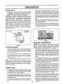
SAFETY
RULES
Practices for
Walk-Behind
Safe Operation
Mowers
IMPORTANT:
THIS CUTTING MACHINE IS CAPABLE OF AMPUTATING
HANDS AND FEET AND THROWING OBJECTS.
FAILURE TO OBSERVE THE FOLLOWING
SAFETY iNSTRUCTIONS
COULD RESULT IN SERIOUS INJURY OR DEATH.
SAFETY STANDARDS REQUIRE OPERATOR PRESENCE CONTROLS TO MINIMIZE THE RISK OF INJURY, YOUR UNIT tS
EQUIPPED WITH SUCH CONTROLS.
DO NOT ATTEMPT TO DEFEAT THE FUNCTION OF THE OPERATOR PRESENCE
CONTROLS UNDER ANY CIRCUMSTANCES.
TRAINING:
•
Plead this operator's manual carefulfy. Become familiar with
the controls and know how to operate your mower propet¥
Learn how to quickly stop mower.
•
Do not continue to run your mower if you hit a foreign object.
Follow the procedure outlined above, then repair any damage before restarting and operating you mower.
•
Do not allow children to use your mower. Never allow adults
to use mower without proper instructions.
•
Do not change the governor settings or overspeed
engine. Engine damage or personal injury may result.
•
Keep tbe*_lr'ea of-op'aration "clear'of a!l persons, especially
small children'and pets.
•
-
Use mower only as the manufacturer
scdbed in this manual.
Do not operate your mower if it vibrates abnormally. Excessive vibration is an indication of damage; stop the engine,
safely check for the cause of vibration and repair as required.
•
Do not run the engine indoors.
ous.
•
Do not operate mower if it has been dropped or damaged in
any manner. Always have damage repaired before using
your mower.
•
•
Do not use accessory attachments that are not recommended
by the manufacturer.
Use of such attachments may be
hazardous.
Never cut grass by pulling the mower towards you. Mow
across the face of slopes, never up and down or you might
lose your footing. Do not mow excessively steep sJopes. Use
caution when operating the mower on uneven terrain or when
changing directions - maintain good footing.
°
•
The blade turns when the engine is running.
Never operate your mower without proper guards, plates,
grass catcher or other safety devices in place.
intended and as de-
the
Exhaust fumes are danger-
PREPARATION:
MAINTENANCE
•
•
Check the blade and the engine mounting bolts often to be
sure they are tightened properly.
•
Check all bolts, nuts and screws at frequent intervals for
proper tightness to be sure mower is in safe working condition.
-
Keep all safety devices in place and working.
•
To reduce fire hazard, keep the engine free of grass, leaves
or excessive grease and oil.
°
Check grass catcher often for deterioration and wear and
replace worn bags. Use only replacement bags that are
recommended by and comply with specifications of the
manufacturer of your mower.
•
Always keep a sharp blade on your mower.
•
Allow engine to cool before storing in any enclosure.
•
Never store mower with fuel in the tank inside a building
where fumes may reach an open flame or an ignition source
such as a hot water heater, space heater, clothes dryer, etc.
Always the roughly check the area to be mowed and clear it of
all stones, sticks, wires, bones, and other foreign objects.
These objects will be thrown by the blade and can cause
severe injury,
•
Always wear safety glasses or eye shields when starting and
while using your mower,
•
Dress properly. Do not operate mower when barefoot or
wearing open sandats. Wear onfy solid shoes with good
traction when mowing.
•
Check fuel tank before starting engine. Do not fill gas tank
indoors, when the engine is running orwhen the engine is hot.
Allow the engine to cool for several minutes before filling the
gas tank. Clean off any spilled gasoline before starting the
engine.
•
•
Always make wheel height adjustments before starting your
mower. Never attempt to do this while the engine is running.
Mow only in daylight or good artificial light.
AND STORAGE:
OPERATION:
•
Keep your eyes and mind on your mower and the area being
cut. Do not let other interests distract you.
•
Do not mow wet or slippery grass. Never run while operating
your mower. Always be sure of your footing - keep a firm hold
on the handles and walk.
o
Do not put hands or feet near or under rotating parts. Keep
clear of the discharge opening at all times.
•
Always stop the engine whenever you leave or are not using
your mower, or before crossing driveways, walks, roads, and
any gravel-covered areas.
•
Never direct discharge of material toward bystanders nor
allow anyone near the mower while you are operating it.
•
Before cleaning, inspecting, or repairing your mower, stop the
engine and make absolutely sure the b_ade and all moving
parts have stopped. Then disconnect the spark plug wire and
keep it away from the spark plug to prevent accidental
starting.
,,,,,,,,,,,,,,,,,,,,,,,,,,,,,
A
-
,,,,,,.,,
Look for this symbol to point out important safety precautions.
It means
CAUTION!!!
BECOMEALERT!!!
YOUR
SAFETY IS INVOLVED.
i i ii iiiiiiii
i
iii
i
iii
i
I
CAUTION:
Always disconnect
spark
plug wire and place wire where it cannot contact spark plug in order to prevent accidental
starting when setting
up, transporting,
adjusting or making
repairs.
i
i iiiiiiiilffilllll
i
ii
ii iiiiiiiiiiiiii
A WARNING
The engine exhaust from this product contains chemicals known to the State of CaliTornia to cause cancer,
reproductive
harm.
iii iiiiii
2
i
birth
defects,
i
or other
iiiiiii
....
I
!
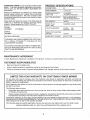
PRODUCT
CONGRATULATIONS
on your purchase of a Sears Lawn
Mower. tt has been designed, engineered and manufactured to give you the_best possibte dependability and
performance,
SPECIFICATmONS
4ORSEPOWER:
..
5.5
DISPLACEMENT:
11.5 CU. IN.
Should you experience any problem you cannot easily
remedy, please contact your nearest Sears Authorized
Service Center/Department.
We have competent, welltrained technicians and the proper tools to service or repair
this lawn mower.
GASOLINE CAPACITY
AND TYPE:
1.5 QUARTS
UNLEADED REGULAR
OIL TYPE (AP!-SF/SG):
SAE 30 (ABOVE 32°F)
SAE 5W-30 (BELOW 32°F)
Please read and retain this manual. The instructioh_;V_ill
enable you to assemble and maintain your lawn mower
properly. AIways observe the "SAFETY RULES".
OIL CAPA(_ITY:
20 OZS.
SPARK PLUG:
(GAP: .030")
CHAMPION J19LM
VALVE CLEARANCE:
INTAKE:
.008
EXHAUST: .008
MODEL
NUI_1BER
917_387850
SERIAL
NUMBER
SOLID STATE IGNITION
AIR GAP:
.0125 IN.
DATEOFPURCHASE
BLADE BOLT TORQUE:
35-40 FT. LBS.
THE MODELAND SERIAL NUMBERS WILL BE FOUND
ON A DECAL ATTACHED TO THE REAR OF THE
LAWN MOWER HOUSING
YOU SHOULD RECORD BOTH SERIAL NUMBER AND
DATE OF PURCHASE AND KEEP IN A SAFE PLACE
FOR FUTURE REFERENCE.
MAINTENANCE
AGREEMENT
A Sears Maintenance Agreement is available on this product.
CUSTOMER
Contact your nearest Sears store for details.
RESPONSIB LITUES
o
Read and observe the safety rules.
o
Follow a regular schedule in maintaining, caring for and using your lawn mower.
*
Follow the instructions
under "Customer Responsibilities"
LllVlmTEDTWO YEAR WARRANTY
and "Storage" sections of this owner's manual.
ON CRAFTSMAN
POWER MOWER
For two years from date of purchase, when this Craftsman Lawn Mower is maintained, fubricated, and tuned up
according to the operating and maintenance instructions in the owner's manual, Sears will repair free of charge any
defect in material or workmanship.
If this Craftsman Lawn Mower is used for commercial or rental purposes, this warranty appties for only 90 days from
the date of purchase.
This Warranty does not cover:
•
Expendable items which become worn during normal use, such as rotary mower blades, blade adapters, belts,
air cleaners and spark plug.
o Repairs necessary because of operator abuse or negligence, including bent crankshafts and the failure to maintain
the equipment according to the instructions contained in the owner's manual.
WARRANTY SERVICE tS AVAILABLE BY RETURNING THE CRAFTSMAN POWER MOWER TO THE NEAREST
SEARS SERVICE CENTER/DEPARTMENT
IN THE UNITED STATES. "THIS WARRANTY APPLIES ONLY WHILE
THIS PRODUCT IS IN USE IN THE UNITED STATES".
This Warranty gives you specific legal rights, and you may also have other rights which vary from state to state.
SEARS, ROEBUCK AND CO., D/817 WA, HOFFMAN ESTATES, ILLINOIS 60179
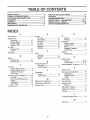
LE OF CONTENTS
SAFETY
RULES
PRODUCT
............................................................
SPECIFICATIONS
2
......................................
SERVICE AND ADJUSTMENTS ................................. 14
STORAGE ...................................................................
15
TROUBLESHOOTING .................................................
21
REPAIR PARTS - LAWN MOWER ........................ 16-17
REPAIR PABTS - ENGINE .................................... 18-20
PARTS ORDERING/SERVICE .................................... 22
3
CUSTOMER RESPONSIBILITIES ..................... 3, 11-13
WARRANTY ..................................................................
3
ASSEMBLY ...................................................................
6
OPERATION ............... _........................................... _...... 8
MAINTENANCE SCHEDULE ...................................... 11
UNDEX
A
Accessories ....................................
Adjustments:
Carburetor .............................
Engine Speed ........................
Handle Height ........................
Height of Cut ............................
Air Filter:
Replacement .........................
Service ...................................
Assembly ........................................
E
5
14
t4
t4
9
13
13
6
B
Btade:
Sharpening ............................
Replacement .........................
12
12
C
Conirols:
Engine Zone Control ................ 9
Engine Speed Control ............. 8
Operator Presence
Control Bar .............................. 8
Customer Responsibilities... 3, 11-13
Air Filter ................................ . 13
Blade Care]Replacement ...... 12
Engine ...................................
13
Lubrication ............................. 13
Spark Plug ............................. 13
Cutting Levels ................................ 9
Engine:
Air Filter .................................
Oil Change .............................
Oil Level .................................
Oil Type .................................
• Starting ..................................
Stopping ................................
Storage ..................................
O
Oil:
13
13
13
13
10
10
15
F
Options:
Accessories
Fuel:
Capacity ................................... 3
Storage .................................. 15
Type ................ ;........................ 9
H
Handle Adjustment:
Assembly ................................. 6
Cutting Height ........................ 14
L
Lubrication:
Engine ...................................
Lawn Mower ..........................
13
11
M
Maintenance Agreement ................ 3
Maintenance Schedule ................. ! 1
Mowing Tips .................................
Engine ...................................
13
Storage ..................................
15
Operation:
Engine Control ......................... 9
Grass Catcher ......................... 9
Mower ......................................
9
Operator Presence
Control Bar .............................. 9
10
.............................
5
R
Repair Parts:
Engine ..............................
Lawn Mower .....................
Responsibilities,
Customer..
18-20
16-17
3, 11-13
S
Safety Rules ...................................
2
Service and Adjustments .............
Carburetor .............................
Engine Speed ..... ;..................
Handle ...................................
14
14
14
14
Spark Plug ....................................
I3
Specifications .................................
Speed Control:
Engine ...................................
3
14
Starting the Engine .................... ;.. 10
Stopping the Engine ..................... 10
Storage .........................................
t5
T
Trouble Shooting Chart ................ 21
W
Warranty .........................................
3
i,i
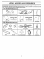
.... LAWN MOWER ACCESSORUES
ii,lu
,
.,
i
,
="_" .....
_
...........
lUll "
I'
I''
These accessories were available when this lawn mower was produced. They are also available at most Sears retail outlets
and service centers. Most Sears stores can also order repair parts for you, when you provide the model n umber of your lawn
mower. Some of these accessories may not apply to your lawn mower.
LAWN MOWER PERFORMANCE
"CLIPPINGDEPLECTOR
FOR REAR DISCHARGE LAWN MOWERS
÷
....
MULCHER KITS
i
GRASS CATCHERS
FOR
REAR DISCHARGE
LAWN MOWERS
STABILIZER
GRASS CATCHERS
FOR
SIDE DISCHARGE
LAWN MOWERS
GAS CANS
LAWN MOWER MAINTENANCE
n
i,i,
.....
MUFFLERS
AIR FILTERS
SPARK PLUGS
,inu, i
BELTS
BLADES
BLADE ADAPTERS
5
WHEELS
ENGINE OIL
=
. =.nn
'
I
ASSE
,
,
LAW_N_MOWER
LY
i,iii1,11........
i
Read these instructions and this manual in its entirety
before you attempt to assemble or operate your new lawn
mower. Your new lawn mower has been assembled atthe
factory with the exception of those parts left unassembled
for shipping purposes. All parts such as nuts, washers,
bolts, etc. necessary tocomplete the _ssembty have been
placed in the parts bag. To ensure safe and proper
operation of your lawn mower, all parts and hardware you
assemble must be tightened securely. Use the correct
tools as necessary to ensure proper tightness.
TO REMOVE
CARTON
m=...mr,,lu=..,
"FROM
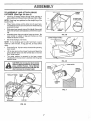
TO INSTALL
(See Fig. 2)
ATTACHMENTS
Your lawn mower was shipped ready to be used as a
mulcher. To convert to bagging or discharging:
o
o
Open rear door and remove mulcher
. mulcher plug in a safe place.
plug..
Store
You can now install catcher or optional clipping deflector.
To return to mulching operation, install mulcher plug
into discharge opening of mower.
"4
•
Remove loose parts included with mower.
•
Cut down two end corners of carton and lay end panel
down flat.
o
Remove all packing materials except padding between
• upper and lower handle and padding holding operator
presence control bar to upper handle.
•
Roll lawn mower out of carton and check carton thoroughly for additional loose parts.
HOWTO SET UPYOUR
TO UNFOLD
HANDLE
LAWN MOWER
MULCHER
(See Fig. 1)
IMPORTANT: UNFOLD HANDLES CAREFULLY SO AS
NOT TO PINCH OR DAMAGE CONTROL CABLES.
•
Raise handles until lower handle section locks into
place in mowing position.
• • Raise upper handle section into place on lower handle,
remove protective padding and tighten both handle
knobs.
,
Remove handle padding holding operator presence
control bar to upper handle.
•
Your lawn mower handle can be adjusted for your
mowing comfort.
Refer to "Adjust Handle" in the
Service and Adjustment section of this manual.
OPERATOR PRESENCE
CONTROLBAR
LIFT UP
MOWING POSITION
LOWER HANDLE
FIG. 1
PLIJ
FIG. 2
ii
CAUTION: Do not run your lawn mower
without mulcher plug in place or approved clipping deflector
or grass
catcher in place. Never attempt to operate the lawn mower with the rear door
removed or propped open.
....
,,,,,,,, ....
,
...............
BLY
TO ASSEMBLE
AND ATTACH GRASS
CATCHER
(See Figs. 3A thru 4)
•
LOWER
FRAME
Insert leg of tubular frame through front opening of
grass catcher and thread frame into sewn hem of bag.
f
I
(Frames must
be fully seated)
__2/
NOTE: Keep bag hem gathered onthe
tubular frame.
straight _eg of the
,
When frame comes out the other end of sewn hem,
immediately work the end of frame down inside the bag
as shown in inset.
-
Slide sewn hemevenly around the tubular frame until
both ends of frame are exposed out bf the front opening.
Assemble lower frame to tubular frame as shown. Be
sure handle is outside of bag and frames are fully
seated as shown in inset.
.
o
TUBULAR
FRAME
/
FiG. 3B
LOWER FRAME HANDLE
Siip vinyl bindings over frame.
NOTE: If vinyl bindings are too stiff, hold them in warm
water for a few minutes. If bag gets wet, let it dry before
using.
•
Close the'ilip lid. Flip lid must be closed while operating
lawn mower.
•
Lift the rear door on the mower housing and"place the
grass catcher frame onto the formed tabs on the rear
door hinge bracket.
°
The grass catcher is secured to the lawn mower
housing when the rear door is lowered onto the grass
catcher frame.
"
A
\
FIG. 3C
_
_ cAUTioN,
Do notrun yourlawn"_""="=='='_mower---_
without clipping deflector orapproved
|
grass catcher in place. Never attempt
|
to operate the lawn mower with the rear
|
--
door removed orp!opped0pen
TUBULAR
FRAME
DOOR
BRACKET
GRASS
CATCHER
FRAME
_
SEWN
FORMED
TABS
FIG, 4
= SEWN HEM
"FL|
LID
FIG. 3A
....
OPERATmON
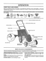
KNOW YOUR LAWN MOWER
READ THIS OWNER'S MANUAL AND SAFETY RULES BEFORE OPERATING YOUR LAWN MOWER. Compare the
illustrations with your lawn mower to familiarize yourself with the location of various controls and adjustments. Save this
manual for future reference.
÷
._.1
....
i
•
These symbols
their meaning.
_ _ ..r_._.
'
......
........
may appear on your lawn mower or in literature
CAUTION
OR WARNING
ENGINE
ON
=l.= 11
ENGINE
OFF
FAST
SLOW
CHOKE
.... =!.=.==
. =IHH....=
111','
=
supplied with the product. Learn and understand
FUEL
OIL
DANGER, KEEP HANDS
AND FEET AWAY
_l.... =......
i
OPERATORPRESENCECONTROLBAR
ZONE CONTROL
CABLE
STARTER HANDLE
HANDLE KNOB
GASOLINE
FILLER CAP
GRASS CATCHER
PRIMER
ENGINE SPEED CONTROL
LEVER
AIR FILTER
LAWN MOWER
MULCHER
HOUSING
PLUG
ENGINE OIL CAP
WITH DIPSTICK
WHEEL ADJUSTER
(ON EACHWHEEL}
MEETS
CPSC SAFETY
REQUIREMENTS
Sears rotary walk-behind power lawn mowers conform to the safety standards of the American National Standards institute
and th'e U.S. Consumer Product Safety Commission. The biade turns when the engine is running.
OPERATOR PRESENCE CONTROL BAR - must be held
down to the handle to start the engine. Release to stop the
engine.
ENGINE SPEED CONTROL - located on the side of the
engine which allows you to select either fast (,_) or slow
(_)
engine speed.
PRIMER - pumps additional fuel from the carburetor to the
cylinder for use when starting a cold engine.
MULCHER PLUG - located at the discharge opening must
be removed when converting to bagging or discharging
operation.
STARTER HANDLE - used for starting the engine.
OPERATION
i
!
i
_
_[ s_Es
_
I
_
_
The operation of any lawn mower can result in foreign objects thrown into the eyes, which can
result in severe eye damage. Always wear safety glasses or eye shields while operating your
lawn mower or performing any adjustments or repairs. We recommend a wide vision safety
mask over the spectacles or standard safety glasses.
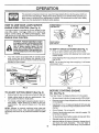
HOW TO USE YOUR LAWN MOWER
ENGINE
SPEED
CONTROL
LOWER WHEELS
FOR HIGH CUT
PLATE TAB
(See Fig. 5)
The engine speed is controlled by a lever located on the
side of..the engine. Fast-(@). position is for starting the
engine, normal Cutting', and be_er gras#'bagging.
Slow
(._) position isfor Jight cutting, trimming and fuet economy.
ENGINE
ZONE
CONTROL
CAUTION: Federal regulations require
an engine control to be installed on this
lawn mower in order to minimize the
RAISE WHEELS
FOR LOW CUT
FIG. 6
under any circumstances attempt to
risk
blade
contact
not
defeatofthe
function
of theinjury.
operatorDo con*
trot. The blade turns when the engine is
running,
•
TO EMPTY GRASS
Your lawn mower is equipped with an opera{or presence control bar whlch requires the operator to be
positioned behind the lawn mower handle to start and
operate the lawn mower.
CATCHER
(See Fig. 7)
o
Lift up on grass catcher using the frame handle.
o
Remove grass catcher with clippings from under lawn
mower handle.
o
Empty clippings from bag using both frame handle and
bag handle.
NOTE: Do not drag the bag when emptying;
unnecessary wear.
it wilt cause
ENGINE SPEED
CONTROL LEVER
,
PRIMER
FIG, 5
FIG. 7
BEFORE STARTUNG ENGINE
TO ADJUST
CUTTING
HEIGHT
(See Fig, 6)
o
Raise wheels for low cut and lower wheels for high cut.
°
Adjust cutting height to suit your requirements.
dium position is best for most lawns.
*
Me-
To change cutting height, squeeze adjuster lever toward wheel. Move wheel up or down to suit your
requirements.
Be sure all wheels are in the same
setting.
NOTE: Adjuster is properly positioned when plate tab
inserts into hole in lever. Atso, 9-position adjusters .(if so.
equipped) allow lever to be positioned between the plate
tabs.
OIL (See Fig, 8)
Your lawn mower is shipped without oil in the engine.
o
Be sure mower is level and area around oil fill is clean.
•
Remove engine oil cap w/dipstick and fill to the full line
on the dipstick.
•
Use 20 ozs. of oil. For type and grade of oil to use, see
"ENGINE" in Customer Responsibilities section of this
manual.
•
Pour oJ'lslowly.
,
Check oil level before each use. Add oil if needed. Fil]
to full line on dipstick.
°
To read proper level, tighten engine oil cap each time.
•
o
Reinstall engine oil cap and tighten.
After the first two (2) hours of mowing, change the oil,
and every 25 hours thereafter.
You may need to
change the oil more often under dusty, dirty conditions.
Do not over fill.
i
.
i ml..,i.rlrl...M
i. I
i, ", .....
Ilrr'll
'
I1"
....
I
.......
'"
r
,"4='44¸
,I
OPERATION
GAS (See Fig. 8)
•
•
Fill fuel tank.
Use fresh, clean, regular unleaded
gasoline with a minimum of 87 octane. Do not mix oi!
with gasoline. Purchase fuel in quantities that can be
used within 30 days to assure fuel freshness,
WARNING: _Experience: indicates'that _lcohol blended
fuels (calted gasohol or using ethanol oi" methanol) can
attract moisture which leads to separation and formation of
acids during storage. Acidic gas can damage the fuel
system of an engine while in storage. To avoid engine
problems, the fuel.system should be emptied before storage of 30 days or:tonger. _:Drain the fuel tank,-st&rtthe
engine and let it run until fuel lines and carburetor are
o
o
o
empty. Use fresh fuel next season. See Storage Instructions for additional information.
Never use engine or
carburetor cleaner products in fuel tank or permanent
damage may occur.
OIL FILL CAP
When using a rear discharge lawn mower in moist,
heavy grass, clumps of cut grass may not enter the
grass catcher. Reduce ground speed (pushing speed)
and/or run the lawn mower overthe area a second time.
Ifatraitofgrassclippingsisleftontherightsideofarear
discharge.lawn mower, mow in a clockwise direction
with a small overlap to collect the clippings on the next
pass.
Keep top of engine around starter clear and clean of
grass clippings and chaff. This witl help engine airflow
and extend engine life.
Poresinclothgrasscatcherscanbecomefi]ledwithdirt
and dust with use and catchers will coltect tess grass.
To prevent this, regu!afly hose catchers off with water
and let dry before using.
GASOLINE
FILLER CAP
MAX 1/3
FIG. 9
MULCHING
FIG. 8
TO START ENGINE
o
To start acold engine, push primerfive (5) times before
trying to start. Use a firm push. This step is not usually
necessary when starting an engine which has already
run for a few minutes.
.
Push engine speed control lever to fast (,_)
°
Hold operator presence control bar down to the handle
and pull starter handle quickly. Do not allow starter
rope to snap back.
o
To stop engine, release operator presencecontrol
position.
•
bar.
NOTE: in cooler weather it may be necessary to repeat
priming steps. In warmerweather over priming maycause
flooding and engine wili not start. If you do flood engine,
wait a few minutes before attempting to start and do not
repeat priming steps.
Under certain conditions, such as very tall grass, it may
be necessary to raise the height of-cut to reduce
pushing effort _nd to keep from overloading the engine
and leaving clumps of grass clippings.
•
For extremely heavy cutting, reduce the width of cut
and raise the rear of the lawn mower housing one (1)
wheel adjuster setting higher than the front for better
discharge of grass.
•
For better grass bagging and most cutting conditions,
the engine speed should be set in the fast (,_) position,
Avoid cutting your lawn when it is wet. Wet grass tends
to form clumps and interferes with the mulching action.
The best time to mow your lawn is the early afternoon.
At this time the grass has dded and the newly cut area
witl not be exposed to the direct sun.
For best results, adjust the lawn mower cutting height
so that the lawn mower cuts off only the top one-third
of the grass blades (See Fig. 9). if the lawn is overgrown it will be necessary to raise the height of cut to
reduce pushing effort andto keep from overloading the
engine and leaving clumps of mulched grass. For
extremely heavy mulching, reduce your width of cut,
mow slowly and raise the rear of the lawn mower one
wheel adjuster setting higher than the front.
MOWING TIPS
•
MOWING TIPS
IMPORTANT:
FOR BEST PERFORMANCE,
KEEP
MOWER HOUSING FREE OF BUILT-UP GRASS AND
TRASH. CLEAN UNDERStDE OF MOWER HOUSING
AFTER EACH USE. SEE "CLEANING" IN CUSTOMER
RESPONSIBILITIES SECTION OF THIS MANUAL.
o The special mulching blade will recut the grass clippings many times and reduce them in size so that as
they fall onto the lawn they wil! disperse into the grass
and not be noticed. Also, the mulched grass will
biodegrade quickly to provide nutrients for the lawn.
Always mulch with your highest engine (blade) speed
as this will provide the best recutting action of the
blades.
,
10
Certain types of grass and grass conditions may require that an area be mulched a second time to completely hide the clippings. When doing a second cut,
mow across or perpendicular to the first cut path.
Change your cutting pattern from week to week. Mow
north to south one week then change to east to west the
next week. This will help prevent matting and graining
of the lawn,
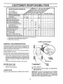
CUSTO
MAINTENANCE
RESPONSRBULITIES,
SCHEDULE
FILL IN DATES
AS YOU COMPLETE
REGULAR SERVICE
M
SERVICE
.Check for Loose Fas.teners................"_"' Ii "
Clean/Inspect Grass Catcher
(ff Equipped)
........ ie" v'
Lawn,,M'ower
'O
_n
V_ Clean Under Drive Cover
(Powb?=Propelled"Mowe'rs)
"c"heckdriv_ belt]pulleys
_
_
"
_....
............
I.....
........
"". '
RE (Pqwer-Propelled Mowers)
_
,
Ch_0_Sh"rpen)_'epiaCe
Bla_'e
.............
Lubrication Chart
"CleanBattery/ReCharge
====(Electric Start Mowers)
1
2
3
4
-
'
t
"
t
............
6/
6/
6/
_
E Check Engine Oil Level
.....
e#' I......
N Chan._e.Engine O!!
......................
644,
G Clean Air Filter
! Inspect M'uffier
...............
....,
E Replace Air Fitter Paper Cartridge
t
I 6/ ......
.
_............
I
==== _===,==
======
_
N Clean£,rRe'place
Sp,ai,k
Ptug , '...............
........
i
J
1
DATES
_'
.................
_ 6/4
_1,2
6/
,,
,
,,,
,,
............................
.........i'J' i,t t ',',,i,',l,il,
'....
Change more often when operating under a heavy lead or in high ambient temperatures,
Service more often when operating in didy or dusty conditions.
Replace blades more o_tan when mowing in sandy soil.
Charge 48 hours at end o! season.
LUBRICATION
GENERAL
RECOMMENDATIONS
CHART
WHEEL
The warranty on this lawn mower does not cover items that
have been subjected to operator abuse or negligence. To
receive full value from th e warranty, operator must maintain
mower as instructed in this manual.
Some adjustments wilt need to be made periodically to
properly maintain your unit,
All adjustments in the Service and Adjustments section of
this manual should be checked at least once each season.
Once a year, replace the spark plug, replace air filter
element and check blade for wear. A new spark plug
and clean/new air filter element assures proper air-fuel
mixture and helps your engine run better and last
longer.
•
(_) ENGINE OIL
Follow the maintenance schedule in this manual.
BEFORE
"
•
(_1 BRAKE
SPRING
BRACKET
EACH
(_) HANDLE BRACKET
MOUNTING PIN
USE
Check engine oil level.
Check for loose fasteners.
LUBRICATION
Keep unit welt lubricated (See "LUBRICATION
REAR
DOOR
HINGE
(_)
SPRAY LUBRICANT
(_)
SAE 30 MOTOR OIL. REFER TO ENGINE - CUSTOMER RESPONSIBILITIES SECTION,
IMPORTANT:
DO NOT OIL OR GREASE PLASTIC WHEEL
BEARINGS.
VISCOUS
LUBRICANTS
WILL ATTRACT
DUST AND DIRT THAT WILL SHORTEN
THE LIFE OF
THE SELF LUBRICATING
BEARINGS. IF YOU FEELTHEY
MUST BE LUBRICATED,
USE ONLY A DRY, POWDERED
GRAPHITE
TYPE LUBRICANT
SPARINGLY.
CHART").
11
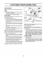
CUSTO
BILITIES
LAWN MOWER
BLADE
ADAPTER
CRANKSHAFT
KEYWAY
,_,
Always observe safety rules when performing any maintenance.
TIRES
o
Keep tires free of gasoline, oil, or insect control chemicals which can harm rubber.
o
Avoid stumps, stones, deep ruts, sharp objects and
other hazards that may cause tire damage.
BLADECARE
.
"
BLADE
_.-
For best results, mower blade must be kept sharp. Replace
bent or damaged btades.
SHAFT
TO REMOVE BLADE (See Fig. 10)
•
Disconnect spark plug wire from spark plug and place
wire where it cannot come [n contact with spark plug.
o
Turn lawn mower on its side. Make sure air filter and
carburetor are up.
•
,
HARDENED
WASHER
LOCK WASHER
TRAILING
EDGE
BLADE ADAPTER
FIG. 10
Use a wood block between btade and mower housing
to prevent blade from turning when removing blade
bolt.
NOTE: We do not recommend sharpening blade - but if you
do, be sure the blade is balanced.
Protect your hands with gloves and/or wrap blade with
heavy cloth.
TO SHARPEN BLADE
=
Remove blade bolt by turning counter-clockwise.
a 9/16 box or opemend wrench.
o
Remove blade and attaching hardware
washer and hardened washer).
Care should be taken to keep the blade balanced. An
unbalanced blade will cause eventual damage to lawn
mower or engine.
Use
(bolt, lock
NOTE: Remove the blade adapter and check the key
ins{de hub of blade adapter. The key must be in good
condition to work properly. Replace adapter if damaged.
•
The blade can be sharpened with a file or on a grinding
wheel. Do not attempt to sharpen while on the mower.
o
To check btade balance, drive a nail into a beam or wall.
Leave about one inch of the straight nail exposed.
Place center hole of blade over the head of the nail. If
blade is balanced, it should remain in a horizontal
position. If either end of the blade moves downward,
sharpen the heavy end until the blade is balanced.
TO REPLACE BLADE (See Fig. 10)
o
Position the blade adapter on the engine crankshaft.
Be sure key in adapter and keyway in crankshaft are
aligned.
GRASS
,
Position biade on the bfade adapter afigning the two (2)
holes in the blade with the raised lugs on the adapter.
,
=
-
Be sure the trailing edge is up toward the engine.
Installthe blade bolt withthe Iockwasher and hardened
washer into blade adapter and crankshaft.
Use block of wood between blade and lawn mower
housing and tighten the blade bolt, turning clockwise.
,
•
o The recommended tightening torque is 35-40 ft. Ibs.
IMPORTANT: BLADE BOLT 1SGRADE 8 HEAT TREATED.
12
CATCHER
The grass catcher may be hosed with water, but must
be dry when used.
Check your grass catcher often for damage or deterioration. Through normat use it will wear. if catcher
needs replacing, replace only with a manufacturer
approved replacement catcher. Give the lawn mower
model number when ordering.
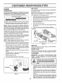
AIR FILTER
ENGINE
_
LUBRICATION
Your engine will not run properly and may be damaged by
using a dirty air filter.
Use only high quality detergent oil rated with AP{ service
classification SForSG. Selectthe oil's SAEviscositygrade
according to your expected operating temperature
Replace the air fitter every year, more often if you mow in
very dusty, dirty conditions. Do not wash air filter.
...............
]'Q CHANGE AIR FILTER (See Fig. 12)
o Removetheairfi]tercover
bytumingcounterclockwise
to the stop and pull away from coltar.
Remove filter from inside of cover.
skEViscosl GRA ES
t
°F
-a0"•
co
_,-
32o4o"
_C -30"
.20_
40 =
(_*
TEMPERATURE RANGE ANTICIPATED
_0o :
.Bo;_
_
40°
20"
BEFORE NEXTOIL
o
looo
30"
.....
40°
CHANGE
o
•
NOTE: Although multi-viscosity oils (5W30, 10W30 etc.)
improve starting in cold weather, these multi-viscosity oils
will result in increased oil consumption when used above
32°F. Check your engine oil levef more frequently to avoid
possible engine damage from running low on oil.
Clean the inside of the cover and the collarto remove
any dirt accumulation.
insert new fifter into cover.
Put air fitter cover and fitter into collar aligning the tab
with the slot.
Push in on cover and turn clockwise to tighten.
COLLAR
Change the oil after the first two hours of operation and
every 25 hours thereafter or at least once a year if the lawn
mower is not 'bsed for 25 hours in one year.
P_
-
,
Check the crankcase oil level before starting the engine
and after each five (5) hours of continuous use. Tighten Oil
plug securely each time you check the oil level.
TO CHANGE ENGINE OIL (See Fig. 11)
NOTE: Before tipping lawn mower to drain oi/, drain" fuel
tank by running engine until fuel tank is empty.
URN
"-._
COUNTER-
/TAB/
AIR FILTER
AIR FILTER COVER
TO TIGHTEN
o
Disconnect spark plug wire from spark plug and place
wire where it cannot come in contact with spark plug.
o
Remove engine oil cap; lay aside on a clean surface.
MUFFLER
*
Tip lawn mower on its side and drain oil into a suitable
container. Rock lawn mower back and forth to remove
any oil trapped inside of engine.
Inspect and reptace corroded muffler as it could create a
fire hazard and/or damage.
*
Wipe off any spilled oil on lawn mower and on side of
engine.
,
Fill engine with oil. Fill only to the "FULL" line on the
dipstick. DO NOT OVER FILL.
CLEANING
*
Replace engine oil cap.
°
Reconnect spark plug wire to spark plug.
IMPORTANT:
FOR BEST PERFORMANCE,
KEEP
MOWER HOUSING FREE OF BUILT-UP GRASS AND
TRASH• CLEAN UNDERSIDE OF MOWER HOUSING
AFTER EACH USE,
FIG. 12
SPARK
PLUG
Change your spark plug each year to make your engine
start easier and run better. Set spark plug gap at.030 inch.
°
Turn lawn mower on its side. Make sure air filter and
carburetor are up. Clean the underside of your lawn
mower by scraping to remove build-up of grass and
trash. "
•o
Clean engine often to keep trash from accumulating. A
clogged engine runs hotter and shortens engine life.
o
Keep finished surfaces and wheels free of all gasoline,
oil, etc.
o
We DO NOT recommend using a garden hose to clean
lawn mower unless the electrical system, muffler, air
filter and carburetor are covered to keep water out.
Water in engine can result in shortened engine life.
CONTAINER
FIG. 11
13
•
i
SERVICE
,
.....
....
C
A
LU T_0N"
o
_o
D ADJUSTMENTS
.........
..
_
B
E
FOa
_
_pE
;FOR
"
U_
AIN
'y
SERVIC
E
O
a"
A
DJ
USITM
ENTS
:
i iiiil!=
ir
ii
........................
,i
i
!
Release control bar.
I
Make sure the blade and all moving parts have completely stopped,
i
• -Diseonn
ct spark PlUg wire from spark plug and place where it cannot come in contact with plug.
I
LAWN MOWER
TO ADJUST
SHIPPING
CUTTING
HEIGHT
See "TO ADJUST CUTTING
section of this manual.-
POSITION
MEDIUM
LOW
MEDIUM HIGH
HEIGHT" in the Operation
.......
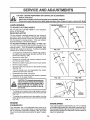
REAR DEFLECTOR
The rear deflector, attached between the rear wheels of
your lawn mower, is provided to minimize the possibility
that objects will be thrown out the rear of the lawn mower
into the operator's mowing position, tf the rear deflector
becomes damaged, it should be replaced
TO ADJUST
HANDLE
(See Figs. 13 Thru
15)
Your lawn mower handle can be raised or tbwered for your
mowing comfort
Four (4) positions are available: high,
medium high, medium low and low Handles are shipped
mounted in the medium tow position
o
•
o
•
•
o
•
•
o
To change from medium low to medium high position,
the upper and lower handle sections will have to be
turned over (See Fig 13B).
Remove the cable clips
Remove the controls and operator presence centre}
bar from the upper handle
Remove the starter rope guide from the lower handle
Remove hairpin cotters,
Disconnect the lower handle from the handle brackets
(See Fig 15)
Turn the handle over and reassemble the hairpin
cotters that have been removed.
Reassemble the starter rope guide
Reassemble the controls and the operator presence
control bar to the upper handle.
FIG. 14A
o
To change from medium
upper handle section will
Fig !4A):
To change from medium
lower handle section witl
Fig. 14B).
FIG. 14B
LOWER HANDLE
CAUTION: The operator presence contro I bar rnu st pivot freely to permit b lade
brake engagement when control bar is
released. Do not over tighten the fasteners holding the controls to the upper handle.
o
FIG. 13B
FIG. 13A
SQUEEZE
TO REMOVE
tow to high position only the
have to be turned over (See
HANDLE
BRACKET
HAIRP1N CLIP
tow to low position, only the
have to be turned over (See
FIG. 15
ENGINE
ENGINE
CARBURETOR
SPEED
Your engine speed has been factory set. Do not attempt
to increase engine speed or it may result in persona1 injury.
If you believe that the engine is running too fast or too slow,
take your lawn mower to an authorized service center for
repair and adjustment.
Your carburetor has a non-adjustable fixed main jet for
mixture control If your engine does not operate properly
due to suspected carburetor problems, take your lawn
mower to an authorized service center for repair or adjustment
14
ALMACENAMIENTO
MOTOR
]nmediatamente prepare su segadora para el almacenamiento al
final de cada temporada o si la unidad no se vaa user por 30 dfas
o m_s.
SISTEMA
SEGADORA
Cuando se va a gua rda r la segadora por clerto perfodo de tiempo,
lfmpiela cuidadcsamente, remueva toda la mugre, ra grasa, ias
hojas, etc. Gu_rdela en un _rea limpia y seca.
o
Limpie toda la segadora (Yea "LIMPIEZA" en la secci6n de
Responsabi]idades del Ctiente de este manual).
=
Lubrfquela seg0n se muestra en la secci6n de Responsabilidades del Cliente de este manual.
•
Aseg0rese de que todas las tuercas y c_avijas y todos los
pernos y tornillcs est_n apretados en foma segura, Inspeccione las partes que se mueven para verificar si est&n
daSadas, quebradas o desgastadas. CAmbielas si es necesario.
°
Retoque todas las superficies que est6n oxidadas o con la
pintura picada; use una lija antes de pintar.
MANGO
o
•
Drene el estanque de combustible.
Haga arrancar el motor y d6jelo funcionar haste que las
lineas del combustible y el carburador est_n vacf'os.
,
Nunca use los #roductos pare limpieza de] carburador o del
motor en el estanque de combustible pues se pueden
producir dafios permanentes.
•
Use combustible nuevo la pr6xima temporada.
AVISO: El estabilizador de combustible es una alternativa aceptable pare reducir a un mfnimo fa fo rmaci6n de dep6sitos de goma
en el combustible durante ef pefiodo de almacenamiento. Agregue estabitizador ata gasotina en el estanque de combustible o
en et envase para el almacenamiento. Siempre siga ta proporci6n
de mezcla que se encuentra en el envase de_estabi_izado_. Haga
funcionar el motor por lo menos 10 minutes despu6s de agregar
el estabilizador, para permitir que este Ilegue al carburador. No
drene la gasolina del estanque de gasolina y el carburador si Se
estA usando estabilizador de combustible.
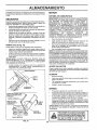
(Vea la Fig. 16)
Puede doblar el mango de su segadora para almacenafla.
°
Apdete los extremes inferiores del mango inferior entre sf
haste que e] mango inferior quede separado del puntaf del
mango, luego mu#valo hacia adelante.
°
Suelte los pernos de montaje del mango superior Io suficiente como pare permitir que el mango superiorse pueda doblar
hacia arras.
IMPORTANTE:
CUANDO DOBLE EL MANGO PARA EL
ALMACENAMFENTO
O EL TRANSPORTE,
ASEGURESE
QUE LO DOBLE SEGUN SE MUESTRA O PUEDE DANAR
LOS CABLES DE CONTROL.
•
Cuando prepare sus mangos a partir de la posici6n
almacenamiento,
el mango inferior autom&ticamente
asegurarA en la posici6n para segar.
DE COMBUSTIBLE
IMPORTANTE: ES IMPORTANTE EVITAR QUE SE FORMEN
DEPOSITOS
DE GOMA EN PARTES FUNDAMENTALES
DEL SiSTEMA
DE COMBUSTIBLE
TALES COMO
EL
CARBURADOR,
EL FILTRO
DEL COMBUSTIBLE,
LA
MANGUERA
DEL COMBUSTIBLE
O EN EL ESTANQUE
DURANTE
EL ALMACENAMIENTO.
LA EXPERtENCIA
TAMBIEN rNDICA QUE LOS COMBUSTIBLES
MEZCLADOS
CON ALCOHOL (CONOCIDO
COMO GASOHOL
O QUE
TIENEN
ETANOL
O METANOL)
PUEDEN
ATRAER
HUMEDAD, LO QUE CONDUCE A LA SEPARACION Y A LA
FORMACION
DE
ACIDOS
D.URANTE
EL
ALyACENAMIENTO.
LA GASOLINA
ACIDfCA
PUEDE
DANAR EL SISTEMA DE COMBUSTIBLE
DE UN MOTOR
DURANTE EL PERfODO DE ALMACENAMIENTO,
de
se
ACEITE
DEL MOTOR
Drene el aceite (con el motor catiente) y c&mbielo con aceite de
motor limpio. (Vea "MOTOR" en la secci6n de Responsabilidades
del Cfiente de este manuaL)
MANGOINFERIOR
CILINDRO
•
•
DEL
MANGO
•
•
CLAVIJA
DE
HORQUILLA
Remueva la bujfa.
Vac[e una onza (29 ml) de aceite a tray,s det agujero de Fa
buj[a en el cilindro.
Tire Ia rear'ilia de arranque ientamente unas cuantas veces
pare distribuir el aceite.
Vuelva a mcntar la nueva bujfa.
OTROS
°
°
No guarde la gasol_'na de una temporada ala otra.
Cambie el envase de la gasolina si se empieza a oxidar. La
ox daci6n yio a mugre en su gaso na produc r_r_pJ'oblemaso
o -. Si es-posible, guarde su unidad en un .recinto cerrado y
c0brata para protegerla contra e! poivo y la mugre.
•
Cubra su unidad con un forro protector adecuado que no
retenga la humedad. No use piAstico. El pI_stico no puede
respirar, _oque permite la formaci6n de condensaci6n, Io que
, producir& ]a oxidaci6n de su unidad.
fMPORTANTE: NUNCA CUBRA LA SEGADORA MIENTRAS
EL MOTOR Y LAS AREAS DE ESCAPE TODAVIA ESTAN
CALIENTES.
BARRA DE CONTROLQUE
EXIGE LA PRESENCIA DEL
OPERADOR
DOBLARHAClA
IADELANTEPARA
ALMACENAR
DOBLAR
HACIA
ATRAS
POSICI6N
PARASEGAR
PRECAUCI6N:
Nunca almaeene
la segado-
edificio en donde los gases pueden alcanra con
zar
unagasolina
llama expuesta
en el estanque
o una dentro
ehispa. dePerun
mlta que se enfrie el motor antes de
almacenarla en afg_in recinto cerrado.
MANGOINFERIOR
FIG. 16
15
.........................................
I.r.... I"lr
f
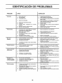
IDENThFICACION
CAUSA
CORRECCION
No arranca
1.
2.
3.
Fiitro de airs sucio.
Sin combustible.
Combustible rancio.
1.
2.
3.
4,
Agua en el combustible.
4.
5.
6.
7.
Alambre de ta buj[a desconectado.
Bujla mala,
Cuehilla
suelta o adaptador
de la cuchilla
quebrado.
Barfs de control en la poslcian suelta.
Barra de control defectuosa.
5.
6.
7.
Falta de fuerza
1,
2.
3.
4.
Mal torte disparejo
Vi6raci6n
excesiva
.......
Cord6n arraneador
diffctl de tirar
L
Dlf|cil de empujar
Parte trasera de la caja]cuchilia de la segadora
arrastr&ndose en e! c_sped pesado.
Est& cortando muahocasped.
Filtro de sire sucio.
Umpietcambie el filtro de sire,
Liens el estanque de combustible.
Drene el estanque y vuelva a llenado con combustible
limpio y nuevo.
Drene el estanque de combustible y el carburador y
vuelva a lfenar el estanque con gasolina nueva.
Conecte et alambre a la bujfa.
Gamble la buj[a.
Apriete eL pemo de la cuchilta o cambie el adaptador
de ]a cuchilLa.
8.
9.
Presione ta barfs de control hacia el mango.
Cambie la barfs de control
.
t i,l,,i
ir HHI'
HI
NH
.......................
t.
Ajaste a la posicibn de "Corte mAs alto."
2.
3,
4.
Ajuste a la posician de "Corte mAs alto,"
Limpie/cambie et filtro de sire.
Limpie fa parte inferior de la caja de [a eegadora,
5,
6.
Revise el nivel del aceite.
Cortea una vaiocidad de recorrido m&s lenta.
5.
Acumulac]Sn de c_sped, hojas y basura debajo
de ta segadora.
Demasiado aceite en el motor.
6.
Velocidad
"L
2.
3.
Cuchilla desgastada, dobiada o suelta.
Altura de]as ruedas dispareja,
Velocidad det motor tents.
1.
2.
3.
Cambie la cuchilla. Apriete el perno de la cuchilta.
Ajuste todas las ruedas a la misma attura.
Pangase en contacto con sa centre de servicio
autorizado m&s cercano.
4.
Acumulacian de cesped, hojas o basura debajo
de la segadom.
4.
Limpie la parts inferior de la caja de la segadora.
l.
2.
Cuchiila desgastada, doblada o suelta.
CigueSal det motor doblado.
1.
2.
Camble la cuchilla. Apriete el perno de la cuchilla.
Pangase en oontaoto con su centre de servicio
autorizado m&s csrcano.
'"'
de recerrido demasiado
.
ii
r&pida.
=..................
,..,.
ii.
1.
El freno del voTante de1motor est& aplicadocua_.do
se suelta la barra de control.
2.
3.
4.
ii ,.I.,IT.I i
Recogedor de
cdsped no se liens
(si viene equipsdo)
I
PROBLEMAS
PROBLEMA
8.
9.
I'"1.................
,....,.,
......................
.1.
Presione la barra de control hacia el mango superior
antes de tirar el cordon arraneador.
Cigue_al de! motor dobtado,
2.
Adaptader de la cuchilla quebrado.
La cuchilla se arrastra en et c_sped.
3.
4.
Pangase en contacto con su centre de servicio
autorizado m&s cercano.
Cambie el adaptador de la cuchilla.
Mueva la segadora aun lugar en deride el c_sped ha
side cortado o a una supefficie firms pars hacer
arrancar el motor.
....................
! i...i
.i
ll.,.
,i
. .PH,,i
i
H,
1.
2.
3.
4.
Altura de carte demasiado baja.
Levantamiento de la cuchiUa desgastado.
Recogedor sin venti_acidn de airs.
Vetoc]dad del motor lanta.
t,
2.
Eleve ta altura de corte.
Cambie tas cuchiL[as.
3.
4.
Limpie el recogedor de c_sped.
Pangase en contacto con su centre
autorizado m&s cercano,
1.
El casped est& demasiado alto o [a altura de t_
rueda demas[ado baja.
Parts trasara de la caja,'cuchilla de fa segadora
arrastr&ndose en el casped.
Recogedorde
c_sped demasiadolleno.
Posicibnde ia aftura de/mango no adecuadapara
usted.
1.
El_va Fa al_ra_d_ cert,.
2.
Eleve ta parte trasera de ta caja de la segadora (1) un
lugar m&s a_to.
Vac[e elrecQgsdor de casped.
Ajustela attura del mango de modoque le acomode.
2.
3.
4.
16
3.
4_.
de servicio
REPAIR PARTS
ROTARY LAWN MOWER - - MODEL NO. 917.387850
KEY
NO.
...,$
"4
1
2
3
4
5
7
8
9
10
11
13
14
15
16
17
18
19
21
22
23
24
25
26
27
28
29
30
3t
32
33
34
35
36
37
38
39
PART
NO.
86902
145646X479
150425
132001
157081X479
131959
151517
51793
136376
156577
750097
850733X004
63601
57143
151023
700483_479
15OO50
54583
140661X479
88652
700365X479
133190X479
14O54O '
61651,
151512X479
15t511X479
750913X004
150078
700325X007
146630
128415
87877
700331X004
145935X004
62335
142748
DESCRIPTION
KEY
NO.
PART
NO.
Control Bar
Upper Handle
Mulcher Plug
Rope Guide
Lower Handle
Handle Bolt
Cable Clip
Hairpin Cotter
Handle Knob
Engine Zone Control Cable
Hex Washer Head Screw 10-24 x 1/2
Up-Stop Bracket
Nut
Wave Washer
Rear Door Assembly Kit
Back Plate
Self Tapping Screw 10-24 x 5/8
Hex Head Tapping Screw 1/4-20 x 1/2
Rear Baffle
Hinge Screw 1/4-20 x 1-1/4
Side Baffle
Discharge Baffle
Rear Deflector
Spring Washer
Handle Bracket Assembly (Left)
Handle Bracket Assembly (Right)
Axle Arm Assembly
Screw 5/16-18 x 3/4
Wheel Adjusting Bracket
Spacer
Pop Rivet
Selector Knob
Selector Spring
Axle Arm Assembly
Betleviile Washer
Shoulder Bolt
40
41
42
43
44
45
46
47
48
49
5O
51
52
53
54
55
56
57
58
151161
151162
83923
77400
48411
15O4O6
85463
751592
88348
149588
700869X479
851084
850263
851O74
141114
851514
144748
154870
......
59
6O
61
62
63
--
144747
74760612
86969
700170X479
700172X479
159077
DESCRIPTION
Wheel
Wheel and Tire Assembly 14 x 2
Hex Flange Locknut
Hubcap
Lawn Mower Housing (IncL Key #18; 22, 24, 46, 50)
Hex Head Thread Rolring Screw 3/8-16 x 1
Danger Decal
Lecknut 3/8-16
Flat Washer 3/8
Seif Tapping Screw w/Sems 5/16-18 x 1-1/2
Front Baffle
Hex Head Machine Screw 3/8-24 × _-3/8 (Grd. 8)
Helical Lockwasher 3/8
Washer
Blade 22"
Blade Adapter
Tube Frame
Grass Bag
Engine (See Breakdown)
Craftsman 143.975510
Throat Frame
Hex Bolt 3/8-16 x 3/4
Spacer
Bracket Support RH
Bracket Support LH
Owner's Manual (English/Spanish)
Available accessories not included with lawn mower:
71 33303
Clipping Deflector
7-1 33623
Gas Can (2.5 gal.)
7-1 33500
Fuel Stabilizer
7_!133300
SAE 30W Oil (20 oz.)
7-1 33417
Dust Shield
71 333!6
Mower Cover
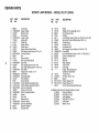
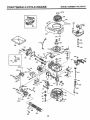
CRAFTSMAN
4-CYCLE ENGINE
MODEL
NUMBER
143.975510
_j
370K"
_ 390
_.qt
_,,,370A_/"
261
_
.
2e7
298
.
9OO
300
t
262/_
40O
135
;7
204
207
239
/_178
370C
<x
238
250
18
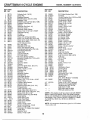
CRAFTSMAN
KEY PART
NO. NO.
I
2
6
7
12
12A
12B
14
15
t6
17
18
19
20
30
40
40
4I
41
36774
26727
33734
36557
36775 ,
36558
36694
28277
30589
34839A
31335 •
651018
36281
32600
36776
40004
40005
36070
36O71
42
42
43
45
46
48
5O
52
69
70
72
75
80
81
82
83
86
89
90
92
93
100
101
103
110
119
120
125
125
40006
40007
20381
36777
32610A
27241
36778
29914
35261
34311D
36O83
27897
30574A
30590A
30591
30588A
650488
611004
611112
650815
650816
34443A
610118
651007
34961
36787
36788
36779
36780
126
126
130
135
150
151
151A
169
172
174
178
182
184
185
186
189
36781
36782
6021A
35395
35991
31673
40017
36783
36784
30200
29752
6201
26756
36785
34337
650839
4-CYCLE ENGINE
KEY-PART
NO. NO,
DESCRIPTION
Cylinder (incl. 2 & 20)
Dowel Pin
Breather Element
Breather Ass'y. (Incl. 6 & 12A)
Breather Tub_
."
.
Breather Cover & Tube (incl. 12[B)
Breather Tube Elbow
Washer
Governor Rod (Incl. 14)
Governor Lever
Governor Lever Clamp
Screw, Tor'x T-15, 8-32 x !9/64" Extension Spring
Oil Seal
Crankshaft
Piston, Pin & Ring Set (Std.)
Piston, Pin & Ring Set (.010" OS)
Piston & Pin Ass'y. (Std.) (Incl. 43)
Piston & Pin Ass'y.
(.010" OS) (Incl. 43)
Ring Set (Std.)
Ring Set (.010" OS)
Piston Pin Retaining Ring
Connecting Rod Ass'y. (Incl. 46)
Connecting Rod Bolt
Valve Lifter
Camshaft (MCR)
Oil Pump Ass'y.
* Mounting Flange Gasket
Mounting Flange (Incl, 72 thru 83)
Oil Drain Plug
Oil Seat
Governor Shaft
Washer
Governor Gear Ass'y. (Inct. 81)
Governor Spool
Screw, 1/4-20x 1-1/4"
Flywheel Key
Flywheel
Beileville Washer
Flywheel Nut
Solid State ignition
Spark Plug Cover
Screw, Torx T-15, 10-24 x 15/16"
Ground Wire
* Cylinder Head Gasket
Cylinder Head
Exhaust Valve (Std.) (Incl. 151)
Exhaust Valve
(1/32" OS) (incl. 151)
Intake Valve (Std.) (Incl. 151)
Intake Valve (1/32" OS) (lncl. 151)
Screw, 5/I6-t8 x 1-!/2"
Resistor Spark Plug (RJ19LM)
Valve Spring
Valve Spring Cap
Intake Valve Seal
* Valve Cover Gasket
Valve Cover
Screw, 10_24 x 9/16"
Nut & Lock Washer, 1/4-28
Screw, 1/4-28 x 7/8"
* Carburetor To Intake Pipe Gasket
Intake Pipe
Governor Link
Screw, 1/4-20 x 3/8"
MODEL
NUMBER
143.975510
191 36559
195 610973
200 35727
202 38482
203 31342204 650549
205 650777
207 34336
209 30200
215 32410
223 650451
224 36786
238 650932
239 34338
241 35797
245 35066
250 35065
260 36980
261 30200
262 650831
275 36790
277 650988
285 35000A
287 650926
290 29774
292 26460
298 28763
300 36916
301 36246
305 35647
306 36832
307 35499
309 650562
310 35648
313 34080
370A 36261
370B 35167
370C 36861
370K 36695
380 640026
390 590694
400 36792 "
416
36085
417 650760
900 -900 --
_.
DESCRIPTION
S.E. Brake Bracket (Incl. 195)
Terminal
Control Bracket (Incl. 202 thru 205)
Compression Spring
Compression Spring
Screw, 5-40 x 7/16"
Screw, 6-32 x 21/32"
Throttle Link
Screw, 10-24 x 9/16"
Control Knob
Screw, 1/4-20 x 1"
* Intake Pipe Gasket
Screw, 10-32 x 49/64"
* Air Cleaner Gasket
Air Cleaner Collar
Air Cleaner Filter
Air Cleaner Cover
Blower Housing
Screw, 10-24 x 9/16"
Screw, 1/4-20 x 1/2"
Muffler (Inct. 277)
Screw, t/4-20 x 2-5/16"
Starter Cup
Screw, 8-32 x 21/64"
Fuel Line
Fuel Line Clamp
Screw, 10-32 x 35/64"
Fuel Tank (Incl. 292 & 301)
Fuel Cap
Oil Fill Tube
* "O"-Ring
"O"-Ring
Screw, 10-32 x 1/2"
.Dipstick
Spacer
Lubrication Decal
Control Decal
Primer Decal
Starter Decal
Carburetor (Incl. 184)
Rewind Starter
Gasket Set
(Incl. Items Marked * in Notes)
Spark Arrestor Kit
(lncL 417)(Optional)
Screw, 8-32 x 3/8" (Optional)
Replacement Engine NONE
Replacement S/B 750796,
order from 71"999
RPM High 2900 to 3200
RPM Low 2450 to 2750
(NOTE: This engine could have been built with 590737
starter. Refer to the design of the rope pulley strength
ribs for part identification. Individual starter parts do not
interchange.). Incl. Part #'s 26756 (1),28833 (1), 36832
(1), 34338 (t), 35261 (1), 36783 (1), 36786 (1),
36787 (1)
NOTE: All component dimensions given in U.S. inches
1 inch = 25.4 mm
19
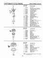
CRAFTSMAN
4-CYCLE ENGINE
MODEL
NUMBER
143.975510
KEY PART
NO. NO.
DESCRIPTION
640026
1
2
4
5
6
7
16
17
18
20
20A
25
27
28
29
30
31
35
36
37
40
44
47
48
..4/@
Carburetor
(Incl. 184 of Engine Parts List
Throttle Shaft & Lever Assembly
Throttle Return Spring
Dust Seal Washer
Dust Seal (Throttle)
Throttle Shutter
Shutter Screw
Fuel Fitting
Throttle Crack Screw/
Idle Speed Screw
Tension Spring
Idle RestdctorScrew
Idle Restdctor Screw Cap
Float Bowl
Float Shaft
Float
Float Bowf"O" Ring
Inlet Needle, Seat, & Clip (Incl. 31)
Spring Clip
Primer Bulb/Retainer Ring
Main Nozzle Tube
"O" Ring, Main Nozzle Tube
High Speed Bowl Nut
Bowl Nut Washer
Welch Plug, Idle Mixture WeLt
Welch Plug, Atmospheric Vent
631615
631767
631184
631!83
631036
650506
631775
650417
630766
640027
640053
631867
631024
632019
631028
631021
631022
36045
632735
632547
640028
27t10
630748
631027
=....
KEY PART
NO. NO.
--
O=-t
1
2
3
4
5
6
7
8
11
590694
590599A
590600
59O696
590601
590697
590698
590699
590700
590695
12
13
590535
590701
n....................
DESCRIPTION
Recoil Starter
Spring Pin (Incl. 4)
Washer
Retainer
Washer
Brake Spring
Starter Dog
Dog Spring
Pulley & Rewind Spring Ass'y.
Starter Housing Ass y.
(40 degree grommet)
Starter Rope ( 98' X 9/64" dia.)
Starter Handle
[j
=
1,,
,,,
=,,
KEY PART
NO, NO.
-3
6
7
8
11
590737
590740
590616
590617
590618A
590687A
12
590535
13
14
590701
590741
NOTE:
2O
DESCRIPTION
Rewind Starter
Retainer
Starter Dog
Dog Spring
Pulley & Rewind Spring Ass'y
Starter Housing Assy
(40 degree grommet)
Starter Rope
(Length 98" x 9/64" dia.)
Starter Handle
Locking Tab
All component dimensions given in U.S. inches
1 inch = 25.4 mm
iii1,111,i ii
..................
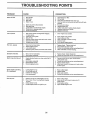
TROUBLESHOOTING
ii
POINTS
,i,
PROBLEM
CAUSE
Doesnot start
1. _ Di_y air filter.
2. Out Of fuel.
3. Stale fuel.
4. Water in fuel.
1.
2..
3,
4.
5.
6.
7.
8.
9.
Spark plug wire is disconnected.
Bad spark plug.
Loose blade or broken blade adapter.
"Control bar in released position
Control bar defective
5.
6.
7.
8.
9.
Clean/replace air filter.
Fill fuel tank.
Drain tank and refill with fresh clean fuel.
Drain fuel tank and carburetor and refill tank with fresh
gasoline.
Connect wire to plug.
Rep{ace spark plug.
Tighten blade bo[t or replace blade adapter.
Depress control bar to handle.
Replace control bar.
1.
Rear of lawn mower housing/blade dragging
in heavy grass.
Cutting too much grass.
Dirty air filter.
Buildup of grass, leaves and trash under mower.
Too much oil in engine.
Walking speed too fast.
1.
Set in "Higher Cut" position.
2,
3.
4.
5.
Set in "Higher Cut" position.
Clean/replace air filter.
Clean underside of mower housing.
Check oil level.
6.
Cut at slower walking speed.
CORRECTION
iii i,ii
Loss of power
2.
3,
4.
5.
6.
,11,1
1,1,11,
,i, i
Poor cut - uneven
iii
Excessive
,i,
vibration
1.
2.
3.
4.
Replace blade, Tighten blade bolt.
Set all wheels at same height.
Contact an authorized service center/department.
Clean underside of mower housing.
1.
2.
Worn, bent or loose blade.
Bent engine crankshaft,
t.
2.
Replace blade, Tighten blade bolt.
Contact an authorized service center/department.
1.
Engine flywheel brake is on when control bar is
released,
Bent engine crankshaft
Blade adapter broken.
Blade dragging in grass.
1.
Depress control bar to upper handle before "
pulling starter rope.
Contact an authorized service center/department.
Replace blade adapter.
Move lawn mower to cut grass or to hard surface
to start engine.
Hill
ill
i
ii ii ¸
i
iii
,11 ii
Hard to push
ii
Worn, bent or loose blade.
Wheel heights uneven,
Low engine speed.
Buildup of grass, leaves, and trash under mower.
2.
3.
4.
Grass catcher not filling
(if so equipped)
i
1.
2.
3.
4.
iiiiii ,11
Starter rope hard to pull
i,iii
i
2.
3.
4.
i1,11, , i
ii iii
,
1.
2.
3.
4.
Cutting height too low.
Lift on blade worn off.
Catcher not venting air.
Low engine speed.
1.
2.
3.
4.
Raise cutting height.
Replace blade.
Clean grass catcher.
Contact an authorized
1.
2,
1.
2.
3.
Grass is too high or wheel height is too low.
Rear of ]awn mower housing/blade dragging
in grass.
Grass catcher too full
4.
Handle height position not right for you.
Raise cutting height.
Raise rear of lawn mower housing one (1)
setting higher.
Empty grass catcher.
Adjust handle height to suit.
21
3,
4.
service center/department.
MgN °
5.5 HORSEPOWER
22" REAR DISCHARGE
ROTARY LAWN MOWER
Each lawn mower has its own model number.
gine has its own model number,
MODEL NO.
917.387850
Each en-
The model number for your ]awn mower will be found on a
decal attached to the rear of the lawn mower housing.
The model number for your engine will be found on the
blower housing of the engine.
All parts listed herein may be ordered from any Sears,
Roebuck and Co. Service Center/Department and most
Retail Stores.
IF YOU NEED
REPAIR SERVICE
OR PARTS:
FOR REPAIR SERVICE, CALL
THIS TOLL FREE NUMBER:
1-800-4-REPAIR
(1_800-473-7247)
WHEN ORDERING REPAIR PARTS, ALWAYS GIVE THE
FOLLOWING INFORMATION:
• PRODUCT - LAWN MOWER
o MODEL NUMBER - 917.387850
• ENGINE - CRAFTSMAN - MODEL NO. 143.975510
• PART NUMBER
,, PART DESCRIPTION
FOR REPLACEMENT PARTS
INFORMATION AND
ORDERING, CALL THIS
TOLL FREE NUMBER:
1-800-FON-PART
(1-800-366-7278)
Your Sears merchandise has added value when you..
consider Sears has service units nationwide staffed with
Sears trained technicians..,
professional technicians
specifically trained to insure that we meet our pledge to
you, we service what we sel!.
22