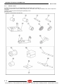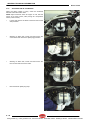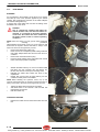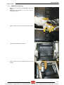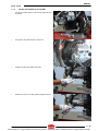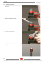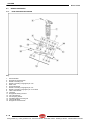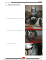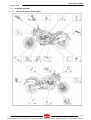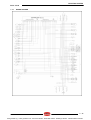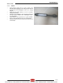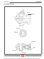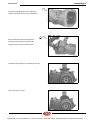
1
Cod. 8140904
UK
workshopmanual
1288 5
00/2005-11
INTRODUCTION
Griso V1100
INTRODUCTION
0
0-1
www.guzzitek.org + www.guzzitech.com - Revente Interdite - Revendita Vietata - Resaling Forbiden - Wiederverkauf Verboten
INTRODUCTION
Griso V1100
SUMMARY
0.1.
INTRODUCTION .............................................................................................................................................. 3
0.1.1.
FOREWORD ............................................................................................................................................. 3
0.1.2.
REFERENCE MANUALS .......................................................................................................................... 4
0.1.3.
ABBREVIATIONS/SYMBOLS/CONVENTIONS ........................................................................................ 5
0-2
www.guzzitek.org + www.guzzitech.com - Revente Interdite - Revendita Vietata - Resaling Forbiden - Wiederverkauf Verboten
Griso V1100
0.1.
0.1.1.
INTRODUCTION
INTRODUCTION
FOREWORD
This manual provides the information required for normal servicing.
This publication is intended for use by Moto Guzzi Dealers and their qualified mechanics; many concepts have been
omitted on purpose as their inclusion would be superfluous. Since complete mechanical explanations have not been
included in this manual, the reader must be familiar with basic notions of mechanics, as well as with basic repair
procedures. Without such familiarity, repairs and checks could be ineffective and even hazardous. Since the repair and
vehicle check instructions are not exhaustive, special care must be taken to avoid damage and injury. Moto Guzzi s.p.a.
undertakes to constantly improve the design of its products and their literature to ensure that the customer is satisfied of
the product. The main technical modifications and changes in repair procedures are communicated to all Moto Guzzi
dealers and agencies world-wide. Such modifications will be entered in subsequent editions of the manual. Should you
need assistance or clarifications about the inspection and repair procedures, please contact the Moto Guzzi SERVICE
DEPT., they will be glad to give you any information on the matter, or supply you with any detail on updates and technical
changes applied to the vehicle.
Moto Guzzi s.p.a. reserves the right to make changes to its products at any time, barring any such changes as may alter
the essential features of a product as specified in the relevant manual.
All rights of storage using electronic means, reproduction and total or partial adaptation, whatever the means adopted,
are reserved in all countries.
Third parties' products are only mentioned for information purposes, and constitute no engagement.
Moto Guzzi s.p.a. is not liable in any way for the performance or use of these products.
For further details, see (REFERENCE MANUALS).
First edition: November 2005
Produced and printed by:
VALLEY FORGE DECA
Ravenna, Modena, Torino
DECA s.r.l.
Legal and Administrative headquarters
Via Vincenzo Giardini, 11
48022 Lugo (RA) - Italy Tel. 0545 - -216611
Fax 0545 - -216610
E-mail: [email protected]
www.vftis.com
DECA s.r.l.
via Vincenzo Giardini, 11 - 48022 Lugo (RA) - Italy
Tel. +39 - 0545 216611
Fax +39 - 0545 216610
E-mail: [email protected]
www.vftis.com
On behalf of:
Moto Guzzi s.p.a.
via E.V. Parodi, 57- 23826 Mandello del Lario (Lecco) - Italy
Tel. +39 – 0341 - 709111
Fax +39 – 0341 - 709220
www.motoguzzi.it
www.servicemotoguzzi.com
0-3
www.guzzitek.org + www.guzzitech.com - Revente Interdite - Revendita Vietata - Resaling Forbiden - Wiederverkauf Verboten
INTRODUCTION
0.1.2.
Griso V1100
REFERENCE MANUALS
PARTS CATALOGUES
guzzi part# (description)
GU078_00
OWNER'S MANUALS
guzzi part# (description)
06.90.00.00
06.90.00.01
CHASSIS WORKSHOP MANUAL
guzzi part# (description)
8140900
8140901
8140902
8140903
8140904
8140905
8CM0095
8CM0096
ENGINE WORKSHOP MANUAL
guzzi part# (description)
8CM0093
8CM0094
0-4
www.guzzitek.org + www.guzzitech.com - Revente Interdite - Revendita Vietata - Resaling Forbiden - Wiederverkauf Verboten
INTRODUCTION
Griso V1100
0.1.3.
ABBREVIATIONS/SYMBOLS/CONVENTIONS
#
<
>
≤
≥
~
∞
°C
°F
±
A.C.
A
Ah
API
AT
AV/DC
bar
D.C.
cc
CO
CPU
DIN
DOHC
ECU
rpm
HC
ISC
ISO
kg
kgm
km
km/h
kΩ
kPa
KS
kW
l
LAP
LED
LEFT SIDE
m/s
max
mbar
mi
MIN
MPH
MS
MΩ
N.A.
N.O.M.M.
N.O.R.M.
Nm
= number
= less than
= greater than
= less than or equal to
= greater than or equal to
= approximately
= infinity
= degrees Celsius (centigrade)
= degrees Fahrenheit
= plus or minus
= alternating current
= Ampere
= Ampere per hour
= American Petroleum Institute
= high voltage
= Anti-Vibration Double Countershaft
= pressure measurement (1 bar = 100 kPa)
= direct current
= cubic centimetres
= carbon monoxide
= Central Processing Unit
= German industrial standards (Deutsche Industrie Norm)
= Double Overhead Camshaft
= Electronic Control Unit
= revolutions per minute
= unburnt hydrocarbons
= Idle Speed Control
= International Standardization Organization
= kilograms
= kilogram metre (1 kgm = 10 Nm)
= kilometres
= kilometres per hour
= kilo Ohm
= kiloPascal (1 kPa = 0.01 bar)
= clutch side (from the German "Kupplungsseite")
= kilowatt
= litres
= racetrack lap
= Light Emitting Diode
= left-hand side
= metres per second
= maximum
= millibar (1 mbar = 0.1 kPa)
= miles
= minimum
= miles per hour
= flywheel side (from the German "Magnetoseite")
= MegaOhm
= Not Available
= Motor Octane Number
= Research Octane Number
= Newton metre (1 Nm = 0.1 kgm)
Ω
= ohm
= pick-up
= Bottom Dead Centre
= Top Dead Centre
= Pneumatic Power Clutch
= right-hand side
= Society of Automotive Engineers
= Secondary Air System
PICK-UP
BDC
TDC
PPC
RIGHT SIDE
SAE
SAS
0-5
www.guzzitek.org + www.guzzitech.com - Revente Interdite - Revendita Vietata - Resaling Forbiden - Wiederverkauf Verboten
INTRODUCTION
TEST
T.B.E.I.
T.C.E.I.
T.E.
T.P.
TSI
UPSIDEDOWN
V
W
Ø
Griso V1100
= diagnostic check
= crown-head Allen screw
= cheese-head Allen screw
= hexagonal head
= flat head screw
= Twin Spark Ignition
= inverted fork
= Volt
= Watt
= diameter
0-6
www.guzzitek.org + www.guzzitech.com - Revente Interdite - Revendita Vietata - Resaling Forbiden - Wiederverkauf Verboten
Griso V1100
GENERAL INFORMATION
GENERAL INFORMATION
1
1-1
www.guzzitek.org + www.guzzitech.com - Revente Interdite - Revendita Vietata - Resaling Forbiden - Wiederverkauf Verboten
GENERAL INFORMATION
Griso V1100
SUMMARY
1.1
STRUCTURE OF THE MANUAL...................................................................................................................... 3
1.1.1
CONVENTIONS USED IN THE MANUAL ................................................................................................. 3
1.1.2
SAFETY WARNINGS ................................................................................................................................ 4
1.2
GENERAL RULES............................................................................................................................................ 5
1.2.1
BASIC SAFETY RULES ............................................................................................................................ 5
1.3
DANGEROUS ELEMENTS............................................................................................................................... 8
1.3.1
WARNINGS ............................................................................................................................................... 8
1.4
RUNNING-IN .................................................................................................................................................. 11
1.4.1
RUNNING-IN ........................................................................................................................................... 11
1.5
POSITION OF THE SERIAL NUMBERS ........................................................................................................ 12
1.5.1
POSITION OF THE SERIAL NUMBERS ................................................................................................. 12
1-2
www.guzzitek.org + www.guzzitech.com - Revente Interdite - Revendita Vietata - Resaling Forbiden - Wiederverkauf Verboten
GENERAL INFORMATION
Griso V1100
1.1
1.1.1
•
STRUCTURE OF THE MANUAL
CONVENTIONS USED IN THE MANUAL
This manual is divided in sections and subsections, each covering a set of the most significant components. For
quick reference, see the summary of sections.
Unless expressly specified otherwise, assemblies are reassembled by reversing the assembly procedure.
The terms "left" and "right" are referred to the motorcycle when viewed from the riding position.
Motorcycle operation and basic maintenance are covered in the "OWNER'S MANUAL".
•
•
•
In this manual any variants are identified with these symbols:
MP
SF
optional
catalytic version
all versions
national certification
European certification (EURO 1 limits)
VERSION:
Italy
United
Kingdom
Austria
Portugal
Finland
Belgium
Germany
France
Spain
Greece
Holland
Malaysia
Chile
Switzerland
Denmark
Japan
Singapore
Slovenia
Israel
South Korea
Croatia
Australia
United States of America
Brazil
South Africa
New Zealand
Canada
1-3
www.guzzitek.org + www.guzzitech.com - Revente Interdite - Revendita Vietata - Resaling Forbiden - Wiederverkauf Verboten
GENERAL INFORMATION
1.1.2
Griso V1100
SAFETY WARNINGS
The symbols and warnings used throughout this manual have the following meanings:
Safety warning. When you find this symbol on the vehicle or in the manual, be careful of the potential
risk of personal injury. Disregarding the instructions identified by this symbol may compromise the
safety of the user, the motorcycle and third parties.
DANGER
Indicates a potential hazard which may result in serious injury or even death.
WARNING
Indicates a potential hazard which may result in minor personal injury or damage to the vehicle.
NOTE The word "NOTE" in this manual identifies important information or instructions.
1-4
www.guzzitek.org + www.guzzitech.com - Revente Interdite - Revendita Vietata - Resaling Forbiden - Wiederverkauf Verboten
Griso V1100
1.2
1.2.1
GENERAL INFORMATION
GENERAL RULES
BASIC SAFETY RULES
CARBON MONOXIDE
When an operation must be performed with the engine running, position the motorcycle outdoors in a well-ventilated
area.
Never run the engine in an enclosed place.
Use an exhaust emission extraction system when working indoors.
DANGER
Exhaust gases contain carbon monoxide, a poisonous gas which, if inhaled, may cause loss of
consciousness or even death.
FUEL
DANGER
The fuel used to operate engines is highly flammable and becomes explosive under particular
conditions.
Refuelling and maintenance operations should be carried out in a well-ventilated area, with the engine
off.
Do not smoke when refuelling or in the proximity of sources of fuel vapours. Avoid contact with bare
flames, sources of sparks and any other source which may ignite fuel or lead to explosion.
DO NOT DISPOSE OF FUEL IN THE ENVIRONMENT.
KEEP AWAY FROM CHILDREN.
HOT COMPONENT PARTS
The engine and exhaust component parts become hot when the engine is running and will stay hot for some time after
the engine has been stopped.
Wear insulating gloves before handling these components or allow for the engine and the exhaust system to cool down
before proceeding.
USED GEARBOX AND FORK FLUIDS
DANGER
Wear latex gloves when servicing.
Prolonged or repeated contact with gear fluid may cause severe skin damage.
Wash your hands thoroughly after handling.
Dispose of it through the nearest waste oil reclamation firm or through the supplier.
Wear latex gloves when servicing.
DO NOT DISPOSE OF FLUID IN THE ENVIRONMENT.
KEEP AWAY FROM CHILDREN.
BRAKE FLUID
WARNING
Brake fluid can damage plastic, rubber or painted parts. When servicing the brake system, protect all
such parts with a clean cloth.
Always wear safety glasses when servicing the brake system.
Brake fluid is highly irritant. Avoid contact with the eyes.
In case of contact with the eyes, rinse thoroughly with cool, clean water and immediately seek medical
attention.
KEEP AWAY FROM CHILDREN.
1-5
www.guzzitek.org + www.guzzitech.com - Revente Interdite - Revendita Vietata - Resaling Forbiden - Wiederverkauf Verboten
GENERAL INFORMATION
Griso V1100
HYDROGEN GAS AND BATTERY ELECTROLYTE
DANGER
The battery electrolyte is a toxic, caustic substance containing sulphuric acid and thus able to cause
severe burns in case of contact.
Wear close-fitting gloves and protective clothing when handling this fluid.
In case of contact with the skin, rinse thoroughly with fresh water.
Always use eye protection as even a very small amount of the battery fluid can cause blindness. If
battery fluid comes in contact with the eyes, flush thoroughly with water for fifteen minutes and
contact an eye specialist immediately.
If battery fluid is swallowed accidentally, drink plenty of water or milk. Seek medical attention
immediately and keep drinking milk of magnesia or vegetable oil in the meantime.
The battery gives off explosive gases. Keep the battery well away from any sources of ignition, such
as flames, sparks, or any heat sources; do not smoke near the battery.
Make sure the area is well ventilated when servicing or refilling the battery.
KEEP AWAY FROM CHILDREN.
Battery fluid is corrosive.
Avoid spillage. Take special care not to spill battery fluid on plastic parts.
Make sure that the electrolyte fluid you are using is the suitable type for your battery.
GENERAL PRECAUTIONS AND INFORMATION
Follow these instructions closely when repairing, disassembling or reassembling the motorcycle or its components.
DANGER
Using bare flames is strictly forbidden when working on the motorcycle. Before servicing or
inspecting the motorcycle: stop the engine and remove the key from the ignition switch; allow for the
engine and exhaust system to cool down; where possible, lift the motorcycle using adequate
equipment placed on firm and level ground. Be careful of any parts of the engine or exhaust system
which may still be hot to the touch to avoid scalds or burns.
Never put mechanical parts or other vehicle components in your mouth when you have both hands
busy. None of the motorcycle components are edible. Some components are harmful to the human
body or toxic.
Unless expressly indicated otherwise, reassemble the units by repeating the disassembly operations
in reverse order. Where a procedure is cross-referred to relevant sections in the manual, proceed
sensibly to avoid disturbing any parts unless strictly necessary. Do not use polishing pastes on matt
paints.
Never use fuel instead of solvent to clean the motorcycle.
Do not clean rubber or plastic parts or the seat with alcohol, petrol or solvents. Use only water and
mild soap.
Always disconnect the battery negative (-) lead before soldering any electrical components.
When two or more persons service the same motorcycle together, special care must be taken to avoid
personal injury.
For further warnings, see DANGEROUS ELEMENTS
BEFORE DISASSEMBLING ANY COMPONENTS
•
Clean off all dirt, mud, and dust and clear any foreign objects from the vehicle before disassembling any
components.
•
Use the model-specific special tools where specified.
DISASSEMBLING THE COMPONENTS
Never use pliers or similar tools to loosen and/or tighten nuts and bolts. Always use a suitable spanner.
Mark the positions of all connections (hoses, wiring, etc.) before disconnecting them. Identify each connection using
a distinctive symbol or convention.
Mark each part clearly to avoid confusion when refitting.
Thoroughly clean and wash any components you have removed using a detergent with low flash point.
Mated parts should always be refitted together. These parts will have seated themselves against one another during
running as a result of normal wear and tear and should never be mixed up with other similar parts when refitting.
Certain components are matched-pair parts and should always be replaced as a set.
Keep away from heat sources.
1-6
www.guzzitek.org + www.guzzitech.com - Revente Interdite - Revendita Vietata - Resaling Forbiden - Wiederverkauf Verboten
Griso V1100
GENERAL INFORMATION
REASSEMBLING THE COMPONENTS
DANGER
Never reuse a circlip or snap ring. These parts must always be replaced with new ones once they have
been removed.
When fitting a new circlip or snap ring, open the ends just enough to allow fitting to the shaft.
Make a rule to check that a newly fitted circlip or snap ring is fully housed in its groove.
Never use compressed air to clean bearings.
NOTE All bearings must run freely with no hardness or noise. Replace any bearings that do not meet these
requirements.
-
Use ORIGINAL Moto Guzzi spare parts only.
Use the specified lubricants and consumables.
Where possible, lubricate a part before assembly.
When tightening nuts and bolts, start with the largest or innermost nut/bolt and observe a cross pattern. Tighten
evenly, in subsequent steps, until the specified torque has been achieved.
Replace any self-locking nuts, gaskets, seals, circlips or snap rings, O-rings, split pins, bolts and screws which have
a damaged thread.
Lubricate the bearings abundantly before assembly.
Make a rule to check that all components you have fitted are correctly in place.
After repairing the motorcycle and after each service inspection, perform the preliminary checks, and then test ride
the motorcycle in a private estate area or in a safe area away from traffic.
Clean all mating surfaces, oil seal edges and gaskets before assembly. Apply a thin layer of lithium grease along the
edges of oil seals. Fit oil seals and bearings with the marking or serial number facing outwards (in view).
ELECTRICAL CONNECTORS
Disconnect electrical connectors as follows: failure to follow these instructions can seriously damage the connectors and
the wiring.
Press the special safety hooks, where fitted.
WARNING
Never separate two connectors by pulling on the wiring.
•
•
•
Grasp both connectors and pull them in opposite directions until they become separated.
Remove dirt, rust, moisture, etc., from inside the connectors with compressed air.
Ensure that the wires are securely crimped to the terminals inside each connector.
NOTE A connector will fit properly only in the matching connector and when inserted in the correct fitting position.
•
Reconnect the two connectors. Ensure that they are correctly coupled (if fitted with hooks, they should click audibly
into place).
TIGHTENING TORQUES
DANGER
Always remember that the tightening torques of all wheel, brake, wheel shaft and other suspension
parts are essential to ensuring safe operation of the motorcycle and must be set to the indicated
values. Ensure that these values are always within the specified limits.
Regularly check the tightening torques on all fastenings, and always use a torque wrench when fitting
them.
Failure to observe these instructions can result in parts loosening or coming away, thus jamming a
wheel or creating other problems which would affect the handling of the motorcycle, potentially
resulting in serious injury or death.
1-7
www.guzzitek.org + www.guzzitech.com - Revente Interdite - Revendita Vietata - Resaling Forbiden - Wiederverkauf Verboten
GENERAL INFORMATION
1.3
1.3.1
Griso V1100
DANGEROUS ELEMENTS
WARNINGS
FUEL
DANGER
The fuel used to operate engines is highly flammable and becomes explosive under particular
conditions.
Refuelling and maintenance operations should be carried out in a well-ventilated area, with the engine
off.
Do not smoke when refuelling or in the proximity of sources of fuel vapours. Avoid contact with bare
flames, sources of sparks or any other source which may ignite the fuel or lead to explosion.
Take care not to spill fuel out of the filler, as it may ignite when in contact with hot engine parts.
In the event of accidental fuel spillage, ensure that the affected area is fully dry before starting the
engine. Fuel expands from heat and when left under direct sunlight.
Never fill the fuel tank up to the rim. Tighten the filler cap securely after each refuelling.
Avoid contact with the skin. Do not inhale vapours. Do not swallow fuel. Do not transfer fuel between
different containers using a hose.
DO NOT DISPOSE OF FUEL IN THE ENVIRONMENT.
KEEP AWAY FROM CHILDREN.
Use only premium grade unleaded petrol, min. O.N. 95 (RON) and 85 (MON).
LUBRICANTS
DANGER
Correct lubrication is essential to the safety of the motorcycle.
Failure to maintain the lubricant level or the use of incorrect, old or dirty lubricant can cause the
engine or transmission to seize, resulting in accident, serious injury or death.
Prolonged or repeated contact with gear fluid may cause severe skin damage.
Wash your hands thoroughly after use.
Do not dispose of oil in the environment.
For disposal, contact the nearest waste oil reclamation firm or the supplier.
WARNING
Avoid spillage when filling the vehicle with oil. Immediately clean up any spilt oil, as it can damage
painted parts.
Oil on the tyres can make them very slippery and dangerous to use.
In case of leaks, do not use the motorcycle. Identify the cause of the leak and repair it.
ENGINE OIL
DANGER
Prolonged or repeated contact with engine oil may cause severe skin damage.
Wash your hands thoroughly after handling.
Do not dispose of oil in the environment.
For disposal, contact the nearest waste oil reclamation firm or the supplier.
Wear latex gloves when servicing.
FRONT FORK FLUID
DANGER
Front suspension response can be modified to a certain extent by changing damping settings and/or
selecting a particular grade of oil. Standard oil viscosity: SAE 20 W. Choose suitable oil grades
according to the desired set-up (choose SAE 5W for a softer suspension, 20W for a stiffer
suspension).
The two grades can also be mixed in varying solutions to obtain the desired response.
1-8
www.guzzitek.org + www.guzzitech.com - Revente Interdite - Revendita Vietata - Resaling Forbiden - Wiederverkauf Verboten
Griso V1100
GENERAL INFORMATION
BRAKE FLUID
NOTE This vehicle is fitted with front and rear disc brakes. Each brake system is operated by an independent hydraulic
circuit. The information provided below applies to both brake systems.
DANGER
Do not drive the vehicle if the brakes are worn or not operating correctly. The brakes are the vehicle’s
most important safety component and using the vehicle with the brakes in less than perfect operating
condition comprises a high probability of traffic accident, which can result in serious injury or death.
The brakes are significantly less effective on a wet road surface.
DANGER
If the road surface is wet, maintain a double braking distance, as both the brakes and the grip of the
tyres are significantly less effective in such conditions.
Water on brakes, whether due to a recent wash or picked up from a wet road surface, puddles or
drains, can result in significantly reduced brake efficiency.
Failure to observe these instructions can result in serious accidents, with the risk of serious personal
injury or death.
The brakes are essential to your safety. Do not drive the vehicle if the brakes on not in perfect
operating condition.
Always check the brakes before riding the motorcycle.
Brake fluid is an irritant. Avoid contact with the eyes or skin.
In the event of accidental contact, wash affected body parts thoroughly. In the event of accidental
contact with the eyes, contact an eye specialist or seek medical attention.
DO NOT DISPOSE OF BRAKE FLUID IN THE ENVIRONMENT.
KEEP AWAY FROM CHILDREN.
Avoid spillage. Brake fluid can damage plastic or painted parts.
DANGER
Do not use brake fluids other than the specified type. Never mix different types of fluids to top up the
level, as this will damage the brake system.
Do not use brake fluid from containers which have been kept open or in storage for long periods of
time.
Any sudden changes in slack or hardness in the brake levers are warning signs of problems with the
hydraulic circuits.
Make sure that the brake discs and brake linings have not come in contact with oil or grease. This is
particularly important after servicing or inspections.
Make sure the brake lines are not twisted or worn.
Avoid accidental entry of water or dust into the circuit.
Wear latex gloves when servicing the hydraulic circuit.
DISC BRAKES
DANGER
The brakes are the vehicle’s most important safety component
To ensure your personal safety, they must be in perfect working order and should be checked before
every ride.
A dirty disc soils the pads.
Dirty pads must be replaced. Dirty or oily discs must be cleaned with a high-quality degreasing
product.
If the vehicle is often used on wet road surfaces or on dusty or rough tracks, or if used in competition,
reduce the service intervals by half.
Check brake pads for wear.
When the brake pads are worn, the fluid level lowers to compensate for the wear.
The front brake fluid reservoir is on the right-hand side of the handlebar, next to the front brake lever.
The rear brake fluid reservoir is located under the right-hand side fairing.
Do not use the vehicle if the brake system leaks fluid.
1-9
www.guzzitek.org + www.guzzitech.com - Revente Interdite - Revendita Vietata - Resaling Forbiden - Wiederverkauf Verboten
GENERAL INFORMATION
Griso V1100
TYRES
WARNING
An over-inflated tyre results in a hard, uncomfortable and less secure ride.
Over inflation also affects grip, especially on curves and wet surfaces.
An under-inflated tyre (insufficient pressure) can slip on the wheel rim, resulting in loss of control.
Under inflation also affects grip and handling, as well as braking efficiency.
Tyre changing and repair, and wheel servicing and balancing are delicate operations. They should be
carried out using adequate tools and are best left to experienced mechanics.
New tyres may be covered with a thin layer of protective coating which is slippery. Drive carefully for
the first few kilometres (miles).
Never use rubber treatment products on the tyres.
In particular, do not allow the tyre to come in contact with liquid fuel, which rapidly deteriorates the
tyre rubber.
In case of contact with oil or fuel, do not clean but change the tyres.
DANGER
Some of the factory-assembled tyres of this vehicle are provided with wear indicators.
There are various types of wear indicators.
For more information on how to check the wear, contact your Dealer.
Check wear visually and have the tyres replaced when they are worn.
If a tyre deflates during a ride, do not attempt to continue the trip.
Avoid sudden braking or steering manoeuvres, and do not decelerate abruptly.
Slowly decelerate and move to the edge of the road braking with the engine until you come to a
standstill.
Failure to observe these instructions can result in accidents, with the risk of serious personal injury or
death.
Never use tube tyres on tubeless tyre rims, or vice versa.
1 - 10
www.guzzitek.org + www.guzzitech.com - Revente Interdite - Revendita Vietata - Resaling Forbiden - Wiederverkauf Verboten
GENERAL INFORMATION
Griso V1100
1.4
1.4.1
RUNNING-IN
RUNNING-IN
Proper engine running in is essential to preserving engine life and performance over time.
Twisty roads and gradients are ideal for breaking in engine, suspension and brakes effectively.
Varying speed frequently is also recommended.
This will vary the amount of stress placed on vehicle components continuously, allowing engine parts to cool down when
less stressed.
While it is important to put a certain amount of stress on engine components during the running-in period, it is equally
important to spare the engine at this stage in the vehicle’s life.
WARNING
Top acceleration performance is only obtained after covering the first 2000 km (1243 mi).
Follow these recommendations:
•
Do not open the throttle completely when the engine is running at low speed, both during and after the running-in
period.
•
Until you have covered the first 100 km (62 mi), use the brakes gently and avoid harsh, prolonged braking. This will
help the brake pads bed in properly against the brake disc.
•
During the first 1000 km (621 mi), never exceed 5000 rpm (see table).
WARNING
After covering the first 1000 km (621 mi), perform the checks listed in the "After running-in" column
(see REGULAR SERVICE INTERVALS CHART) to avoid personal injury to yourself or third persons, or
vehicle damage.
•
•
After the first 1000 km (621 mi) and until covering 2000 km (1243 mi), drive more briskly, varying speed and using
maximum acceleration for just a few seconds, in order to ensure better component coupling; never exceed 6000
rpm (see table).
After the first 2000 km (1243 mi) you may run the engine harder, however, without exceeding the maximum rpm
allowed (7600 rpm).
Recommended maximum rpm
Mileage km (mi)
0-1000 (621)
1000-2000 (621-1243)
Over 2000 (1243)
rpm
5000
6000
7600
1 - 11
www.guzzitek.org + www.guzzitech.com - Revente Interdite - Revendita Vietata - Resaling Forbiden - Wiederverkauf Verboten
GENERAL INFORMATION
1.5
1.5.1
Griso V1100
POSITION OF THE SERIAL NUMBERS
POSITION OF THE SERIAL NUMBERS
These numbers are necessary for vehicle registration.
NOTE Altering the vehicle's identification numbers is
punishable by law with heavy fines and penalties. Altering
the frame number voids the warranty.
This number consists of figures and letters as shown in the
example below.
ZGULP00005MXXXXXX
Key:
ZGU: WMI (World manufacture identifier) code;
LP: model;
000: version;
0: free digit
5 year of manufacture variable (5 = 2005)
M: manufacturing facility (M= Mandello del Lario);
XXXXXX: progressive number (6 digits);
FRAME NUMBER
The frame number is stamped on the right-hand side of the
headstock.
ENGINE NUMBER
The engine number is stamped on the left-side, near the
engine oil level plug.
1 - 12
www.guzzitek.org + www.guzzitech.com - Revente Interdite - Revendita Vietata - Resaling Forbiden - Wiederverkauf Verboten
Griso V1100
GENERAL TECHNICAL INFORMATION
GENERAL TECHNICAL INFORMATION
2
2-1
www.guzzitek.org + www.guzzitech.com - Revente Interdite - Revendita Vietata - Resaling Forbiden - Wiederverkauf Verboten
GENERAL TECHNICAL INFORMATION
Griso V1100
SUMMARY
2.1
TECHNICAL INFORMATION............................................................................................................................ 3
2.1.1
TECHNICAL DATA.................................................................................................................................... 3
2.1.2
SCHEDULED MAINTENANCE CHART .................................................................................................... 5
2.1.3
LUBRICANT TABLE .................................................................................................................................. 7
2.1.4
TIGHTENING TORQUE SETTINGS ......................................................................................................... 8
2.1.5
SPECIAL TOOLS .................................................................................................................................... 12
2.1.6
ARRANGEMENT OF THE MAIN ELEMENTS......................................................................................... 14
2.1.7
LOCATION OF INSTRUMENTS/CONTROLS......................................................................................... 16
2.2
MAINTENANCE OPERATIONS ..................................................................................................................... 18
2.2.1
CHANGING ENGINE OIL AND OIL FILTER ........................................................................................... 18
2.2.2
TRANSMISSION OIL............................................................................................................................... 20
2.2.3
GEARBOX FLUID.................................................................................................................................... 21
2.2.4
CLEANING THE AIR FILTER .................................................................................................................. 22
2.2.5
ADJUSTING VALVE CLEARANCE ......................................................................................................... 24
2.2.6
FRONT BRAKE ....................................................................................................................................... 26
2.2.7
REAR BRAKE.......................................................................................................................................... 28
2.2.8
GENERATOR BELT TENSIONING ......................................................................................................... 31
2-2
www.guzzitek.org + www.guzzitech.com - Revente Interdite - Revendita Vietata - Resaling Forbiden - Wiederverkauf Verboten
GENERAL TECHNICAL INFORMATION
Griso V1100
2.1
2.1.1
TECHNICAL INFORMATION
TECHNICAL DATA
DIMENSIONS
Max. length
Max. width
Max. height
Seat height
Wheelbase
Minimum ground clearance
Weight in running order
2260 mm (88.98 in.)
880 mm (34.64 in.)
1070 mm (42.12 in.) (excluding the rear/view mirrors)
800 mm (31.49 in.)
1554 mm (61.18 in.)
185 mm (7.28 in.)
240 kg (529.1 lb)
ENGINE
Type
Number of cylinders
Cylinder arrangement
Total displacement
Bore/stroke
Compression ratio
Starting
Engine idling speed
Clutch
Lubricating system
Air filter
Cooling system
twin-cylinder, 90° V transversal, 4-stroke engine
two
V, 90°
1064 cu cm (65 cu in)
92 x 80 mm (3.6 x 3.1 in).
9.6 : 1
electric
1100 ± 100 rpm
dry, twin disc
System under pressure, adjustment by valves and vane pump
cartridge, dry
air cooled
TIMING SYSTEM
Timing diagram:
2 valves, with rods and rocker arms
Values with inspection clearance between intake 0.10 mm (0.0039 in.)
rocker arms and valve
exhaust 0.15 mm (0.0059 in.)
CAPACITIES
Fuel (reserve included)
Fuel reserve
Engine oil
Gearbox fluid
Transmission fluid
Fork oil
Seats
Max. vehicle load
TRANSMISSION SYSTEM
primary drive
gearbox
overall gear ratios:
1st gear
2nd gear
3rd gear
4th gear
5th gear
6th gear
final drive
ratio
FUEL SYSTEM
Type
Choke
Fuel
FRAME
Type
Steering head angle
Trail
17.2 litres
3.3 litres
Engine oil and oil filter change 3600 cu. cm (219 cu in)
500 cu cm (30.5 cu in)
380 cu cm (23.2 cu in)
520±2.5 cu cm (31.7 ± 1.5 cu in) (per leg)
2
210 kg (462.97 lb) (rider + passenger + luggage)
gear, ratio: 24/35 = 1:1.4583
Mechanic, with 6 speeds, controlled by a pedal on engine left side
17/38 = 1:2.2353
20/34 = 1:1.7
23/31 = 1:1.3478
26/29 = 1:1.1154
31/30 = 1:0.9677
29/25 = 1:0.8621
with cardan joint
12/44 = 1:3.6667
Electronic injection (Weber – Marelli) with stepper motor
Ø 36 mm (1.417 in.)
Premium grade unleaded petrol, minimum octane rating 95 (RON)
and 85 (MON).
Tube, with double cradle in high-strength steel
26°30’
108 mm (4.25 in.)
2-3
www.guzzitek.org + www.guzzitech.com - Revente Interdite - Revendita Vietata - Resaling Forbiden - Wiederverkauf Verboten
GENERAL TECHNICAL INFORMATION
SUSPENSIONS
Front
Wheel travel
Rear
Wheel travel
BRAKES
Front
Griso V1100
Hydraulic upside-down telescopic fork Ø 43 mm (1.69 in); spring
preload, compression and rebound damping are adjustable.
120 mm (4.72 in.)
single-sided with progressive linkage, monoshock with adjustable
rebound and compression damping and spring preload
110 mm (4.33 in.)
Rear
Twin stainless steel floating disc - Ø 320 mm (12.60 in), callipers with
four separate opposed pistons
Stainless steel disc Ø 282 mm (11.10 in)
WHEEL RIMS
Type
Front
Rear
3 hollow spokes in aluminium alloy, chill cast
3.5" x 17”
5.5" x 17”
TYRES
Type
Front
Rear
Dunlop D208 RR - Metzeler rennsport - Pirelli diablo corsa -Michelin
pilot power
Size: 120/70 - ZR 17” 58 W
Inflating pressure: 2.3 atm (230 kPa)
Inflating pressure with passenger: 2.3 atm (230 kPa)
Size: 180/55 - ZR 17” 73 W
Inflating pressure: 2.5 atm (250 kPa)
Inflating pressure with passenger: 2.7 atm (270 kPa)
SPARK PLUGS
Internal (long life)
External
Electrode gap
NGK PMR8B
NGK BPR6ES
0.6 – 0.7 mm (0.024 – 0.028 in.)
ELECTRIC SYSTEM
Battery
Main fuses
Auxiliary fuses
Generator (with permanent magnet)
12 V – 18 Amp/h
30 A
3 A – 15 A – 20 A
12 V – 550 W
BULBS
Parking light
Low beam bulb/high beam
Turn indicator light
Stop/rear parking lights
Instrument panel lighting
Number plate light
12 V – 5 W
12 V – 55 W / 60W H4
12 V – 10 W
LED
LED
12 V – 5 W
WARNING LIGHTS
Turn indicators
Oil pressure
Neutral
Side stand down
High beam
Fuel reserve
Alarm, gear shift indicator
LED
LED
LED
LED
LED
LED
LED
2-4
www.guzzitek.org + www.guzzitech.com - Revente Interdite - Revendita Vietata - Resaling Forbiden - Wiederverkauf Verboten
GENERAL TECHNICAL INFORMATION
Griso V1100
2.1.2
SCHEDULED MAINTENANCE CHART
OPERATIONS TO BE PERFORMED BY THE Moto Guzzi Authorised Dealer (AND CAN BE PERFORMED BY THE
USER AS WELL).
1 = check and clean, adjust, lubricate or change, if necessary;
2 = clean;
3 = replace;
4 = adjust.
NOTE Perform maintenance operations more frequently if the vehicle is used in rainy and dusty areas, on uneven
ground, or for racing.
(*) = Change every 5000 Km (3125 mi), if used for racing
(**) = Check every two weeks or at indicated intervals.
Component
External plugs (*)
Engine oil filter (*)
Fork
Headlight beam direction - operation
Light system
Safety switches
Brake fluid
Engine oil
Tyres
Tyre pressure (**)
Idling rpm
Battery terminal tightening
Head bolt tightening
Engine oil pressure warning light
Brake pad wear
Emptying the oil drain hose from filter box end
After running-in
[1500 km (621 mi)]
3
1
1
1
3
1
4
4
1
4
1
Every 10000 km
Every 20000 km
(6250 mi) or 12
(12500 mi) or 24
months
months
3
3
1
1
1
1
1
3
1
4
4
at every starting: 1
before every trip and
every 2000 km (1250 mi): 1
Every 5000 km (3125 mi): 2
2-5
www.guzzitek.org + www.guzzitech.com - Revente Interdite - Revendita Vietata - Resaling Forbiden - Wiederverkauf Verboten
GENERAL TECHNICAL INFORMATION
Griso V1100
OPERATIONS TO BE PERFORMED BY THE Moto Guzzi Authorised Dealer.
1 = check and clean, adjust, lubricate or change, if necessary;
2 = clean;
3 = replace;
4 = adjust.
NOTE Perform maintenance operations more frequently if the vehicle is used in rainy and dusty areas, on uneven
ground, or for racing.
(*) = Change every 5000 Km (3125 mi), if used for racing
(**) = Check every two weeks or at indicated intervals.
Component
Gearbox fluid
Idle mixture (CO)
Transmission and control cables
Steering bearings and steering play
Wheel bearings
Brake discs
Air filter
Vehicle general operation
Brake systems
Brake fluid
Front fork fluid
Fork oil seals
Brake pads
Adjusting the valve clearance
Wheels / Tyres
Tightening of nuts and bolts
Battery terminal tightening
Cylinder synchronisation
Suspensions and trim
Final transmission fluid
Fuel hoses
Brake lines
Clutch wear (*)
Internal spark plugs
Generator belt
Head stud bolt tightening
Exhaust pipe flange bolts
Every 10000 km
Every 20000 km
(6250 mi) or 12
(12500 mi) or 24
months
months
3
3
1
1
1
1
1
1
1
1
1
3
1
1
1
1
3
after the first 10000 km (6250 mi)
and then every 20000 km (12500 mi): 3
after the first 30000 km (18750 mi)
and then every 20000 km (12500 mi): 3
every 2000 km (1250 mi): 1 - if worn: 3
4
4
1
1
1
1
1
1
1
1
1
3
3
1
Every four years: 3
1
Every four years: 3
1
4
every 20000 km (12500 mi): 4, every 50000 km (31250 mi): 3
4
1
-
After running-in
[1000 km (621 mi)]
2-6
www.guzzitek.org + www.guzzitech.com - Revente Interdite - Revendita Vietata - Resaling Forbiden - Wiederverkauf Verboten
GENERAL TECHNICAL INFORMATION
Griso V1100
2.1.3
LUBRICANT TABLE
LUBRICANT
Engine oil
PRODUCT
RACING 4T 5 W 40
RECOMMENDED:
As an alternative to recommended oils, top brand oils meeting or exceeding
CCMC G-4 A.P.I. SG specifications can be used.
Transmission fluid
RECOMMENDED:
TRUCK GEAR 80 W 90
Gearbox fluid
RECOMMENDED:
ROTRA MP/S 85 W 90
Front fork fluid
Bearings and other
lubrication points
Battery terminals
Brake fluid
RECOMMENDED:
FORK 5W or
F.A. 5W or
FORK 20W.
F.A. 20W, as an alternative
BIMOL GREASE 481,
AUTOGREASE MP or
RECOMMENDED:
GREASE SM2.
As an alternative to recommended grease, use top brand rolling bearing
grease that will resist a temperature range of -30°C to +140°C (-22°F to
+284°F), with dripping point 150°C to 230°C (302°F to 446°F), high
corrosion protection, good resistance to water and oxidisation.
Use neutral grease or Vaseline.
RECOMMENDED:
Autofluid FR. DOT 4 (the braking system is also
compatible with DOT5); or
BRAKE 5.1 DOT 4 (the braking system
is also compatible with DOT 5).
As an alternative to the recommended product, top brand brake fluid
meeting or exceeding SAE J1703, NHTSA 116 DOT 4, ISO 4925
specifications for synthetic brake fluid can be used.
NOTE Use new brake fluid only. Do not mix different makes or types of oil
without having checked bases compatibility.
2-7
www.guzzitek.org + www.guzzitech.com - Revente Interdite - Revendita Vietata - Resaling Forbiden - Wiederverkauf Verboten
GENERAL TECHNICAL INFORMATION
DESCRIPTION
Q.ty
Engine to frame front fastening
2
Gearbox to frame fastener (M12x250 + M12x230)
FRAME
M12x50
TIGHTENING
TORQUE
(Nm)
TIGHTENING TORQUE SETTINGS
SCREW / NUT
2.1.4
Griso V1100
NOTE
80
1+1
M12
50
Gearbox rh plate fastener
2
M8X30
25
Blow-by sec.plate fastener
1
M6X16
10
Coil plate fastener
4
M6x20
10
Electronic control unit fastener
2
M6x20
10
Bushes to electronic control unit fastener
2
10
Loctite 243
Rear reservoir rubber blocks to frame fastener
2
Man
Loctite 243
Air box pins fastener
2
M6X35
Silentbloc
k M6
M6
Lh and rh footrest plate to frame top fastener
2+2
M8X30
25
stainl.steel – A4 –80
Lh and rh footrest plate to frame bottom fastener
2+2
M8x75
18
stainl.steel – A4 –70
Brake switch to plate fastener
1
M8
Man.
Chromed ring to plate fastener
6
M5x10
6
Cable rings to rh footrest plate fastener
3
M5x10
6
10
Pitch 1
FOOTRESTS AND LEVERS
Footrest rubber mat fastener
8
M6x12
10
Rider footrest safety pin M8
2
M8
25
Passenger footrests support to side plates fastener
4
M10X30
38
Rider heel guard to plates fastener
4
M5X15
6
Passenger heel guard fastener
4
M4X10
3
Linkage fastening nut
1+1
M6
10
Brake/gear change lever pin fastener
1+1
M6X16
10
1
M6x20
10
1+1
M8
15
Pre-selector lever fastener
Brake/gear change lever pin fastener
stainl.steel – A4 –70
Self-locking nut
Apply Loctite 243
SIDE STAND
Stand plate to engine top fastener
1
M10X25
50
Stand plate to engine bottom fastener
2
M8X25
25
Side stand securing pin
1
M10x1.25
10
Switch screw
1
M6x20
10
Lock nut
1
M10x1.25
30
Stand cable guide to engine fastener
1
M10
50
Side lever section fastener
2
M6X16
10
Loctite 243
Loctite 243
2-8
www.guzzitek.org + www.guzzitech.com - Revente Interdite - Revendita Vietata - Resaling Forbiden - Wiederverkauf Verboten
Swinging arm clamp to bush fastener
Q.ty
SCREW / NUT
DESCRIPTION
TIGHTENING
TORQUE
(Nm)
GENERAL TECHNICAL INFORMATION
Griso V1100
SWINGING ARM
2
6X25
Note
10
Swinging arm to bevel gears fastener
4
M10x35
50
Linkage to bevel gears fastener
1
M10x50
50
Linkage to frame fastener
1
M10x50
50
Swinging arm shaft to swinging arm fastener
1
M12x1.25
60
Preload bush to swinging arm shaft fastener
1
M25x1.5
10
FRONT SUSPENSION
FRONT FORK
Tube stop plate to bottom yoke fastener
2
M5x16
6
Fork leg to steering head fastener
2
M8X30
20
Fork leg to bottom yoke fastener
6
M8X30
Steering tube ring nut
1
M35x1
22
22
18
40
Steering tube lock ring nut
1
M35x1
Man.
0 to 90 degrees
Steering head plug
1
M29x1
100
Use a torque wrench
2+2
M8X40
25
Fork clamps blanking
Stainl.steel A4 cl. 80
Stainl.steel A4 cl. 80
First tighten top screw to 22 Nm
Then tighten bottom screw to 22 Nm
Then tighten centre screw to 18 Nm
REAR SUSPENSION
SHOCK ABSORBER
Shock absorber to frame fastener 8.8
1
M10x80
50
CONNECTING RODS
Double connecting rod/shock absorber fastener
10.9
Single connecting rod/double connecting rod
fastener 10.9
Single connecting rod to frame fastener 8.8
Double connecting rod/swinging arm fastener 10.9
1
M10x47
40
1
M10x95
50
1
M10x85
50
1
M10x82
50
AIR BOX – BLOW BY
Expansion tank spacer to engine fastener
1
M6
10
Blow by expansion tank to spacer fastener
1
M6
10
Air box to frame fastener
2
M6x20
10
EXHAUST
Exhaust pipe to engine fastener
4
M8x1.25
25
Silencer connecting tube to frame fastener
1
M8X50
25
Silencer to footrest support fastener
2
M8X45
25
Protection to connection tube fastener
1
M6
10
Oxygen sensor fastener
1
M18x1.5
38
Clamp fastener
3
M6
10
2-9
www.guzzitek.org + www.guzzitech.com - Revente Interdite - Revendita Vietata - Resaling Forbiden - Wiederverkauf Verboten
GENERAL TECHNICAL INFORMATION
TIGHTENING
TORQUE
(Nm)
Q.ty
SCREW / NUT
DESCRIPTION
Griso V1100
FRONT WHEEL
1
M25x1.5
REAR WHEEL
Wheel shaft nut
Note
80
Disc fastener
6
M8x20
25
Rear wheel fastener
4
M12x65
110
BRAKING SYSTEM
Front brake rh and lh callipers fasteners
2+2
M10x28
50
REAR SYSTEM
Rear brake calliper fastener
2
M10X30
50
Rear brake fluid reservoir fastener
1
SWP5x20
3
Rear brake reservoir support to plate fastener
1
M6X16
10
Rear brake lever lock nut
1
M6
Man.
2
M6x20
10
Brake master cylinder fasteners
Apply Loctite 243
HANDLEBAR AND CONTROLS
Handlebar lower U-bolts to steering head fastener
2
M10X40
50
2+2
M8X30
25
2
M6x60
10
2+2
M6
10
Rh and Lh dip switch fasteners
2
M5
1.5
Clutch master cylinder to gearbox fastener
3
M6
10
1+1
M10
Man.
Handlebar upper U-bolts fastener
Counterweights fasteners
Brake and clutch master cylinder U-bolts fasteners
Mirror
stainl.steel – A4 –-80
ELECTRIC SYSTEM
Coil fastener
8
M4x25
2
Horn fastener
2
M8
15
Odometer sensor to bevel gears fastener
2
M4X10
3
INSTRUMENT PANEL AND HEADLIGHT
Instrument panel support to headlight support
2
M6X16
10
fastener
Instrument panel support to steer.head fastener
2
M6X16
10
Instrument panel fasteners
3
SWP5x14
3
Headlight support to bottom yoke fastener
2
M8x35
25
2+2
M6
Headlight fasteners
2
M8X30
15
Tail light to tail guard fastener
4
SWP5x14
3
Front+rear turn indicators fasteners
2 - 10
www.guzzitek.org + www.guzzitech.com - Revente Interdite - Revendita Vietata - Resaling Forbiden - Wiederverkauf Verboten
Q.ty
SCREW / NUT
DESCRIPTION
TIGHTENING
TORQUE
(Nm)
GENERAL TECHNICAL INFORMATION
Griso V1100
Note
FUEL TANK
Tank breather fitting
Pump support to tank fastener
FUEL PUMP FLANGE
2
M6
6
6
M5x16
6
TANK
Union to tank fastener
4
M5x16
5
Plug ring nut to tank fastener
4
M5X15
5
Screws to plug ring nut (aesthetic)
4
M5X15
5
Tank to frame front fastening
2
M6X35
10
Battery box and tank to frame rear fastener
2
M6X25
6
BODYWORK
FRONT
Front mudguard fastener
2+2
M5
6
2
M5
6
1+1
M5
Conveyor to frame low. front fastener
1+1
M5
Man
Man
Conveyors to frame rear fastener
1+1
Electronic control unit fastener
Conveyor to frame upp. front fastener
Conveyors to conveyor clos.fastener
M5
self2X3
tapping
REAR
Man
Man
Cat's eye to support fastener
1
M5
4
Cat's eye support to number plate holder fastener
Reinforcement to number plate holder and light
fastener
Number plate holder to low.clos. fastener
2
1
M5x12
4
M5
4
2
self-tapp.
Man
Tail guard low.clos. to frame fastener
4
M8x35
25
Fuse bracket and relay supp. fastener
4
M5
4
ACCESSORIES
Ignition switch fastener – shear bolt
2
M8x28
Shear completely
2 - 11
www.guzzitek.org + www.guzzitech.com - Revente Interdite - Revendita Vietata - Resaling Forbiden - Wiederverkauf Verboten
GENERAL TECHNICAL INFORMATION
2.1.5
Griso V1100
SPECIAL TOOLS
Suitable tools are required for correct disassembly and reassembly and a good set-up.
The use of special tools avoids possible damage that could result from using unsuitable tools and/or improvised
techniques.
Following is a list of special tools designed specifically for this
particular vehicle.
If necessary, request generic special tools.
2 - 12
www.guzzitek.org + www.guzzitech.com - Revente Interdite - Revendita Vietata - Resaling Forbiden - Wiederverkauf Verboten
Griso V1100
Pos.
1
2
3
4
5
6
7
8
9
10
11
12
13
14
15
16
A
GENERAL TECHNICAL INFORMATION
Description
Tool for swingarm shaft ring nut
Tool to tighten steering head
Drift grip
Ball joint seal drift
Transmission box oil seal drift
Sprocket oil seal drift
Sprocket nut spanner
Transmission box support
Bevel gear pair support
Belt tensioning tool
Tool for fitting Ø 41 mm seal
Disassembly operations protections
Drilled rod for bleeding air from damper rod
Weight to be applied to tool aprilia part# AP8140145 (tool for assembling the seal Ø 41
mm) and aprilia part# AP8140189 [tool for assembling the oil seal for hole Ø 43. Accessory
to kit aprilia part# AP8140151 (complete fork tool kit)]
Shim/Damper rod separator plate
Tool to hold spacer
Complete fork tool kit
Part no.
05912630
AP8140190
05902732
05902733
05902731
05902735
05902734
05902730
05902736
06948600
AP8140145
AP8140149
AP8140150
AP8140146
AP8140148
AP8140147
AP8140151
2 - 13
www.guzzitek.org + www.guzzitech.com - Revente Interdite - Revendita Vietata - Resaling Forbiden - Wiederverkauf Verboten
GENERAL TECHNICAL INFORMATION
2.1.6
Griso V1100
ARRANGEMENT OF THE MAIN ELEMENTS
LEFT SIDE
Key:
1.
2.
3.
4.
5.
6.
7.
8.
9.
10.
11.
12.
13.
14.
15.
16.
17.
Headlight
Instrument panel
Left rear-view mirror
Fuel tank filler plug
Fuel tank
Left side body panel
Battery
Main fuse carrier (30A)
Rider/passenger seat
Passenger grab handle
Tool kit compartment
Passenger left footrest
Seat latch
Rider left footrest
Gearbox control lever
Engine oil level dipstick
Side stand
2 - 14
www.guzzitek.org + www.guzzitech.com - Revente Interdite - Revendita Vietata - Resaling Forbiden - Wiederverkauf Verboten
Griso V1100
GENERAL TECHNICAL INFORMATION
RIGHT SIDE
Key:
1.
2.
3.
4.
5.
6.
7.
8.
9.
10.
11.
12.
13.
Rear stop switch
Glove compartment
Rear brake fluid reservoir
Right body panel
Right rear-view mirror
Front brake fluid reservoir
Oil cooler
Engine oil filter
Rear brake lever
Rider right footrest
Transmission with cardan shaft
Right passenger footrest
Single-sided swingarm
2 - 15
www.guzzitek.org + www.guzzitech.com - Revente Interdite - Revendita Vietata - Resaling Forbiden - Wiederverkauf Verboten
GENERAL TECHNICAL INFORMATION
2.1.7
Griso V1100
LOCATION OF INSTRUMENTS/CONTROLS
INSTRUMENTS AND CONTROLS
Key:
1.
2.
3.
4.
5.
6.
7.
8.
9.
10.
11.
12.
13.
Clutch control lever
Ignition switch/steering lock (
Instruments and indicators
Front brake lever
Throttle grip
- )
Light dimmer switch (
Display functions selector
High beam flasher button ( )
SET button
Starter button ( )
Engine stop button ( - )
Horn button ( )
Turn indicator switch ( )
)
2 - 16
www.guzzitek.org + www.guzzitech.com - Revente Interdite - Revendita Vietata - Resaling Forbiden - Wiederverkauf Verboten
Griso V1100
GENERAL TECHNICAL INFORMATION
INSTRUMENTS AND INDICATORS
Key:
1.
2.
3.
4.
5.
6.
7.
8.
9.
Rev counter
Green neutral light ( )
Orange fuel reserve warning light ( )
Red engine oil pressure warning light (
)
Yellow side stand warning light ( )
Green turn indicator warning light ( )
Blue high beam warning light ( )
Red alarms/immobiliser warning light ( )
Multifunction digital display.
2 - 17
www.guzzitek.org + www.guzzitech.com - Revente Interdite - Revendita Vietata - Resaling Forbiden - Wiederverkauf Verboten
GENERAL TECHNICAL INFORMATION
2.2
Griso V1100
MAINTENANCE OPERATIONS
2.2.1
CHANGING ENGINE OIL AND OIL FILTER
CHECKING AND TOPPING UP
WARNING
Check the engine oil level when the engine is
hot.
NOTE Letting the engine idle with the vehicle at standstill is
not the correct procedure to warm the engine and engine oil
up to operating temperature for an oil check. Oil is best
checked after taking a short ride; 15 Km (10 mi) will be
enough.
•
•
•
Stop the engine.
Keep the vehicle upright with both wheels on the
ground.
Unscrew and remove the dipstick (1).
•
Check the oil level using the dipstick (1).
•
The level is correct when it is near the MAX mark.
MAX= maximum level
MIN = minimum level.
If necessary, top up the engine oil level as follows:
•
Unscrew and remove the dipstick (1).
•
Top up with engine oil (see LUBRICANT TABLE) until
the level is above the minimum mark MIN.
WARNING
Do not add additives or other substances to the
fluid.
If you use a funnel or other tool, ensure it is
perfectly clean.
CHANGING ENGINE OIL
NOTE Change oil when it is hot, as it will be more fluid and
will drain more easily.
•
•
Place a container holding more than 4000 cu cm under
the drain plug (2).
Unscrew and remove the drain plug (2).
2 - 18
www.guzzitek.org + www.guzzitech.com - Revente Interdite - Revendita Vietata - Resaling Forbiden - Wiederverkauf Verboten
Griso V1100
•
•
•
•
•
•
GENERAL TECHNICAL INFORMATION
Unscrew and remove the filler plug (3).
Drain the oil into the container and let all remaining oil
drip out for several minutes.
Check the sealing washers of the drain plug (2) and
replace them if worn.
Clean off any metal debris sticking to the drain plug (2)
magnet.
Refit the drain plug (2) and tighten.
Fill with fresh engine oil (see LUBRICANT TABLE)
until the level is above the minimum mark MIN.
CHANGING THE ENGINE OIL FILTER
•
Using the suitable wrench, remove the engine oil filter
from its seat (unscrew).
NOTE Do not use filters that have already been used.
•
•
Smear some oil on the new oil filter seal.
Using the suitable wrench, fit and tighten the new oil
filter to the torque of 18 – 20 Nm.
2 - 19
www.guzzitek.org + www.guzzitech.com - Revente Interdite - Revendita Vietata - Resaling Forbiden - Wiederverkauf Verboten
GENERAL TECHNICAL INFORMATION
2.2.2
Griso V1100
TRANSMISSION OIL
CHECKING AND TOPPING UP
•
•
•
•
Keep the vehicle upright with both wheels on the
ground.
Unscrew and remove the level plug (1).
The correct level is just below the hole of the level plug
(1).
If the oil is below the specified level, top up (see
LUBRICANT TABLE) until the level plug hole (1) is
reached.
WARNING
Do not add additives or other substances into
the fluid.
If you use a funnel or other tool, ensure it is
perfectly clean.
CHANGING ENGINE OIL
WARNING
Change oil when the unit is hot, as oil will be
more fluid and will drain more easily.
NOTE Letting the engine idle with the vehicle at standstill is
not the correct procedure to warm the engine and engine oil
up to operating temperature for an oil check. Oil is best
checked after taking a short ride; 15 Km (10 mi) will be
enough.
•
•
•
•
•
•
•
•
3
Place a container holding more than 400 cm3 (25 in )
under the drain plug (3).
Unscrew and remove the drain plug (3).
Unscrew and remove the breather plug (2).
Drain the oil into the container and let all remaining oil
drip out for several minutes.
Check the sealing washer of the drain plug (3) and
replace it if worn.
Clean off any metal debris sticking to the drain plug (3)
magnet.
Refit the drain plug (3) and tighten.
Pour fresh engine oil in the inlet hole (1) - see
LUBRICANT TABLE - until the level reaches the hole
of the level plug (1).
WARNING
Do not add additives or other substances into
the fluid.
If you use a funnel or other tool, ensure it is
perfectly clean.
•
Refit and tighten the plugs (1 – 2).
2 - 20
www.guzzitek.org + www.guzzitech.com - Revente Interdite - Revendita Vietata - Resaling Forbiden - Wiederverkauf Verboten
Griso V1100
2.2.3
GENERAL TECHNICAL INFORMATION
GEARBOX FLUID
CHECKING AND TOPPING UP
WARNING
Check the gearbox oil level when the engine is
hot.
NOTE Letting the engine idle with the vehicle at standstill is
not the correct procedure to warm the engine and engine oil
up to operating temperature for an oil check. Oil is best
checked after taking a short ride; 15 Km (10 mi) will be
enough.
•
•
Stop the engine.
Keep the vehicle upright with both wheels on the
ground.
•
Unscrew and remove the inspection plug (1) on the
right side of the gearbox.
•
The correct level is just below the hole of the
inspection plug (1).
If necessary:
•
Top up with oil (see 2.1.3 LUBRICANT TABLE) until
the level reaches the hole of the inspection plug (1).
WARNING
Do not add additives or other substances to the
fluid.
If you use a funnel or other tool, ensure it is
perfectly clean.
CHANGE
NOTE Change oil when it is hot, as it will be more fluid and
will drain more easily.
•
Place a suitable container under the drain plug (2).
•
•
•
Unscrew and remove the drain plug (2).
Unscrew and remove the filler plug (1).
Drain the oil into the container and let all remaining oil
drip out for several minutes.
Check the sealing washers of the drain plug (2) and
replace if worn.
Clean off any metal debris sticking to the drain plug (2)
magnet.
Refit the drain plug (2) and tighten.
Fill with fresh oil (see 2.1.3 LUBRICANT TABLE) until
the level reaches the hole of the inspection plug (1).
Tighten the filler plug (1).
•
•
•
•
•
WARNING
Do not add additives or other substances to the
fluid.
If you use a funnel or other tool, ensure it is
perfectly clean.
2 - 21
www.guzzitek.org + www.guzzitech.com - Revente Interdite - Revendita Vietata - Resaling Forbiden - Wiederverkauf Verboten
GENERAL TECHNICAL INFORMATION
2.2.4
Griso V1100
CLEANING THE AIR FILTER
•
Disconnect the connector on the end of the air
temperature sensor.
•
Slide out and move the main fuse box from its housing.
•
Loosen and remove the six screws.
•
Raise the air box cover.
2 - 22
www.guzzitek.org + www.guzzitech.com - Revente Interdite - Revendita Vietata - Resaling Forbiden - Wiederverkauf Verboten
Griso V1100
•
Remove the air filter frame.
•
•
Remove the air filter.
Plug the intake duct with a clean cloth to prevent dirt
from falling into the intake ducts.
GENERAL TECHNICAL INFORMATION
DANGER
Do not start the engine when the air filter is not
in place. Use compressed air to clean the filter
and aim the jet of air inside out.
2 - 23
www.guzzitek.org + www.guzzitech.com - Revente Interdite - Revendita Vietata - Resaling Forbiden - Wiederverkauf Verboten
GENERAL TECHNICAL INFORMATION
2.2.5
Griso V1100
ADJUSTING VALVE CLEARANCE
When the timing system is noisy, check the clearance
between valves and rocker arms.
NOTE Adjust clearance when the engine is cold, with the
piston at top dead centre (TDC) during the compression
stroke (valves closed).
•
Loosen and remove the three screws and remove the
side protection.
•
Working on either side, loosen and remove the two
outer screws and remove the spark plug protection.
•
Working on either side, loosen and remove the two
inner screws and remove the insert.
•
Disconnect both spark plug caps.
2 - 24
www.guzzitek.org + www.guzzitech.com - Revente Interdite - Revendita Vietata - Resaling Forbiden - Wiederverkauf Verboten
GENERAL TECHNICAL INFORMATION
Griso V1100
•
•
Loosen and remove the eight screws.
Remove the head cover.
•
•
Loosen the nut (1);
Turn the adjuster screw (2) with a screwdriver until the
following clearances are set:
•
intake valve:
exhaust valve:
0.10 mm (0.0039 in)
0.15 mm (0.0059 in).
Measure clearance using a suitable feeler gauge (3).
NOTE If clearance is greater than specified, the tappets will
be noisy; clearance smaller than specified will prevent the
valves from closing fully leading to:
-
pressure leak;
engine overheating;
burnished valves, etc.
2 - 25
www.guzzitek.org + www.guzzitech.com - Revente Interdite - Revendita Vietata - Resaling Forbiden - Wiederverkauf Verboten
GENERAL TECHNICAL INFORMATION
2.2.6
Griso V1100
FRONT BRAKE
BLEEDING
Any air trapped in the hydraulic circuit will act as a cushion
and take up most of the pressure applied by the master
cylinder; this will impair the operation of the brake callipers
and reduce braking efficiency.
A spongy feel of the brake lever and loss of braking mean
that there is air in the circuit.
DANGER
This is a dangerous condition that makes the
vehicle unsafe to ride; each time the brakes are
removed, it is essential to bleed the hydraulic
circuit once the brakes have been refitted and
the brake system is back to normal operating
conditions.
NOTE The following procedure applies to both front brake
callipers. Place the vehicle on level ground before beginning
the bleeding procedure. While bleeding the hydraulic circuit,
top up the reservoir with brake fluid as required. Ensure that
there is always some fluid in the reservoir throughout the
process.
•
•
•
•
•
•
Remove the rubber cap from bleeding valve and the
reservoir plug.
Insert one end of a transparent plastic tubing inside the
front brake calliper bleed valve and the other end in a
container.
Turn the handlebar to the left, quickly pull and release
several times the front brake lever, and keep it
completely pulled.
Slacken the bleed valve by 1/4 of a turn to let the brake
fluid drain into the container; this will remove any
tension from the lever and help it travel fully home.
Retighten the bleed valve before the lever is fully
squeezed in.
Repeat this process until the fluid draining into the
container is totally clear of air bubbles.
NOTE While bleeding the hydraulic circuit, top up the
reservoir with brake fluid as required. Ensure that there is
always some fluid in the reservoir throughout the process.
•
•
•
Tighten the bleed valve and remove the tubing.
Add brake fluid to the reservoir until the fluid has
reached the correct level.
Refit the rubber cap.
CHANGING THE PADS
•
•
Remove the vibration damping plate and move the
pistons apart.
Turn the pins and slide out both split pins.
2 - 26
www.guzzitek.org + www.guzzitech.com - Revente Interdite - Revendita Vietata - Resaling Forbiden - Wiederverkauf Verboten
Griso V1100
•
Remove both pins.
•
Remove the vibration damper.
•
Remove one pad at a time.
GENERAL TECHNICAL INFORMATION
WARNING
Do not operate the brake lever when the pads
are not in place or the calliper pistons might
come out of their housing, thus causing brake
fluid leakage.
•
Install two new pads, fit them so the holes match those
on the calliper.
WARNING
Always change both pads and ensure that they
are correctly in place inside the calliper.
•
•
•
•
•
Fit the vibration damper; remember that the arrow must
indicate the direction of travel.
Insert both pins.
Fit both split pins.
Pull the brake lever several times to take the pistons
against the pads.
Check the brake fluid level.
2 - 27
www.guzzitek.org + www.guzzitech.com - Revente Interdite - Revendita Vietata - Resaling Forbiden - Wiederverkauf Verboten
GENERAL TECHNICAL INFORMATION
2.2.7
Griso V1100
REAR BRAKE
BLEEDING
Any air trapped in the hydraulic circuit will act as a cushion
and take up most of the pressure applied by the master
cylinder; this will impair the operation of the brake callipers
and reduce braking efficiency.
A spongy feel of the brake lever and loss of braking mean
that there is air in the circuit.
DANGER
This is a dangerous condition that makes the
vehicle unsafe to ride; each time the brakes are
removed, it is essential to bleed the hydraulic
circuit once the brakes have been refitted and
the brake system is back to normal operating
conditions.
NOTE Place the vehicle on level ground before beginning
the
bleeding
procedure.
While bleeding the hydraulic circuit, top up the reservoir with
brake fluid as required. Ensure that there is always some
fluid in the reservoir throughout the process.
•
•
•
•
•
•
•
Remove the bleed valve rubber cap.
Insert one end of a transparent plastic tubing inside the
rear brake calliper bleed valve and the other end in a
container.
Remove the rear brake reservoir plug.
Push and slowly release of the rear brake lever several
times, then keep it pushed completely.
Slacken the bleed valve by 1/4 of a turn to let the brake
fluid drain into the container; this will remove any
tension from the lever and help it travel fully home.
Retighten the bleed valve before the lever is fully
squeezed in.
Repeat this process until the fluid draining into the
container is totally clear of air bubbles.
NOTE While bleeding the hydraulic circuit, top up the
reservoir with brake fluid as required. Ensure that there is
always some fluid in the reservoir throughout the process.
•
•
•
Tighten the bleed valve and remove the tubing.
Add brake fluid to the reservoir until the fluid has
reached the correct level.
Refit the rubber cap.
CHANGING THE PADS
•
Release the brake line and the throttle cable from the
ties.
2 - 28
www.guzzitek.org + www.guzzitech.com - Revente Interdite - Revendita Vietata - Resaling Forbiden - Wiederverkauf Verboten
Griso V1100
•
Loosen and remove the two screws.
•
•
Turn the pin and slide out the split pin.
Remove the split pin.
•
•
Remove the pin.
Move the pistons apart pushing on the worn pads.
•
Remove one pad at a time.
GENERAL TECHNICAL INFORMATION
WARNING
Do not operate the brake lever when the pads
are not in place or the calliper pistons might
come out of their housing, thus causing brake
fluid leakage.
•
Install two new pads, fit them so the holes match those
on the calliper.
WARNING
Always change both pads and ensure that they
are correctly in place inside the calliper.
2 - 29
www.guzzitek.org + www.guzzitech.com - Revente Interdite - Revendita Vietata - Resaling Forbiden - Wiederverkauf Verboten
GENERAL TECHNICAL INFORMATION
•
•
•
•
Insert the pin.
Fit the split pin.
Push the rear brake lever until the pistons are against
the new pads.
Check the brake fluid level.
•
Fit the calliper to the disc and tighten the two screws.
•
Fit new ties and secure the oil line and the speed
sensor cable to the frame.
Griso V1100
2 - 30
www.guzzitek.org + www.guzzitech.com - Revente Interdite - Revendita Vietata - Resaling Forbiden - Wiederverkauf Verboten
Griso V1100
2.2.8
GENERAL TECHNICAL INFORMATION
GENERATOR BELT TENSIONING
•
Working on either side, loosen and remove the three
screws securing the side body panels.
•
Working on the right side, loosen and remove the two
nuts securing the exhaust manifold, collect two
washers per nut.
•
•
Loosen the manifold clamp.
Remove the right exhaust manifold.
•
Loosen and remove the two screws securing the
control unit protection.
2 - 31
www.guzzitek.org + www.guzzitech.com - Revente Interdite - Revendita Vietata - Resaling Forbiden - Wiederverkauf Verboten
GENERAL TECHNICAL INFORMATION
•
Loosen and remove the two screws securing the
control unit.
•
•
Remove the control unit.
Disconnect the two connectors.
•
Loosen and remove the ground cable bolt.
•
Loosen and remove engine oil recovery tank screw.
Griso V1100
2 - 32
www.guzzitek.org + www.guzzitech.com - Revente Interdite - Revendita Vietata - Resaling Forbiden - Wiederverkauf Verboten
Griso V1100
•
Loosen and remove the spacer.
•
Loosen and remove timing cover screw.
•
•
Loosen and remove the four screws on timing cover.
Remove the timing cover.
•
Loosen the lock nut.
GENERAL TECHNICAL INFORMATION
2 - 33
www.guzzitek.org + www.guzzitech.com - Revente Interdite - Revendita Vietata - Resaling Forbiden - Wiederverkauf Verboten
GENERAL TECHNICAL INFORMATION
•
Using the belt tensioning tool (part no. 06948600),
tension the belt to the specified value.
•
Tighten the adjuster.
•
Tighten the lock nut.
•
Follow the procedure as previously indicated, in the
reverse order for refitting the removed components;
start with installing the timing cover.
Griso V1100
2 - 34
www.guzzitek.org + www.guzzitech.com - Revente Interdite - Revendita Vietata - Resaling Forbiden - Wiederverkauf Verboten
FUEL SYSTEM
Griso V1100
FUEL SYSTEM
3
3-1
www.guzzitek.org + www.guzzitech.com - Revente Interdite - Revendita Vietata - Resaling Forbiden - Wiederverkauf Verboten
FUEL SYSTEM
Griso V1100
SUMMARY
3.1
FUEL SYSTEM ................................................................................................................................................. 3
3.1.1
FUEL SUPPLY SYSTEM DIAGRAM ......................................................................................................... 3
3.1.2
REMOVING THE FUEL TANK .................................................................................................................. 4
3.1.3
REMOVING THE AIR BOX........................................................................................................................ 7
3.2
INJECTION ....................................................................................................................................................... 9
3.2.1
INJECTION SYSTEM DIAGRAM .............................................................................................................. 9
3-2
www.guzzitek.org + www.guzzitech.com - Revente Interdite - Revendita Vietata - Resaling Forbiden - Wiederverkauf Verboten
Griso V1100
3.1
FUEL SYSTEM
FUEL SYSTEM
3.1.1
FUEL SUPPLY SYSTEM DIAGRAM
Key:
1.
2.
3.
4.
5.
6.
7.
8.
Complete fuel pump
Flanged screw M5x16
Fitting
Clamp
Fuel hose
Three-way union
Clamp 12.5x8
Hose
3-3
www.guzzitek.org + www.guzzitech.com - Revente Interdite - Revendita Vietata - Resaling Forbiden - Wiederverkauf Verboten
FUEL SYSTEM
3.1.2
Griso V1100
REMOVING THE FUEL TANK
•
Working on either side, loosen and remove the three
screws and remove the side body panel.
•
•
Remove the seat.
Loosen and remove the two screws.
•
Loosen and remove the two screws and set aside the
two T-shaped spacers.
•
Disconnect the battery negative (-) lead.
3-4
www.guzzitek.org + www.guzzitech.com - Revente Interdite - Revendita Vietata - Resaling Forbiden - Wiederverkauf Verboten
Griso V1100
•
Disconnect the battery positive (+) lead.
•
Loosen and remove the two screws.
•
Remove the battery bracket.
•
Remove the battery and the cover, collect the breather
hose.
FUEL SYSTEM
3-5
www.guzzitek.org + www.guzzitech.com - Revente Interdite - Revendita Vietata - Resaling Forbiden - Wiederverkauf Verboten
FUEL SYSTEM
•
•
Raise the fuel tank from the front, then from behind,
and rest it onto the brackets welded to the frame,
provided with rubber blocks.
Disconnect the quick-release fitting.
•
•
Disconnect the connector.
Remove the fuel tank.
•
For fuel tank installation procedure, follow the
preceding instructions in the reverse order.
Griso V1100
3-6
www.guzzitek.org + www.guzzitech.com - Revente Interdite - Revendita Vietata - Resaling Forbiden - Wiederverkauf Verboten
Griso V1100
3.1.3
•
•
FUEL SYSTEM
REMOVING THE AIR BOX
Remove the fuel tank (see REMOVING THE FUEL
TANK).
Disconnect the connector on the end of the air
temperature sensor.
•
Slide out and move the main fuse box from its housing.
•
Loosen and remove the four screws.
•
Slide out and move the auxiliary fuse box from its
housing.
3-7
www.guzzitek.org + www.guzzitech.com - Revente Interdite - Revendita Vietata - Resaling Forbiden - Wiederverkauf Verboten
FUEL SYSTEM
•
Loosen and remove the two screws.
•
•
Disconnect the vacuum tube.
Disconnect the blow-by reservoir breather hose.
•
Remove the hose ties.
•
Remove the tie from water breather hose on air box
right side and remove the hose.
Working on either side, loosen and remove the tie.
Remove the air box from behind, collect the blow-by
drain hose.
•
•
Griso V1100
3-8
www.guzzitek.org + www.guzzitech.com - Revente Interdite - Revendita Vietata - Resaling Forbiden - Wiederverkauf Verboten
Griso V1100
3.2
3.2.1
FUEL SYSTEM
INJECTION
INJECTION SYSTEM DIAGRAM
3-9
www.guzzitek.org + www.guzzitech.com - Revente Interdite - Revendita Vietata - Resaling Forbiden - Wiederverkauf Verboten
FUEL SYSTEM
Griso V1100
Key:
1.
2.
3.
4.
5.
6.
7.
8.
9.
10.
11.
12.
13.
14.
Electronic control unit
Ignition switch
Battery
Fuel pump
Coils
Instrument panel
Air temperature sensor
Throttle position sensor
Injectors
Engine temperature sensor
Crankshaft position sensor
Side stand
Oxygen sensor
Bank angle sensor
3 - 10
www.guzzitek.org + www.guzzitech.com - Revente Interdite - Revendita Vietata - Resaling Forbiden - Wiederverkauf Verboten
LUBRICATION SYSTEM
Griso V1100
LUBRICATION SYSTEM
4
4-1
www.guzzitek.org + www.guzzitech.com - Revente Interdite - Revendita Vietata - Resaling Forbiden - Wiederverkauf Verboten
LUBRICATION SYSTEM
Griso V1100
SUMMARY
4.1
LUBRICATION SYSTEM .................................................................................................................................. 3
4.1.1
LUBRICATION SYSTEM DIAGRAM ......................................................................................................... 3
4.1.2
REMOVING THE OIL COOLER ................................................................................................................ 4
4-2
www.guzzitek.org + www.guzzitech.com - Revente Interdite - Revendita Vietata - Resaling Forbiden - Wiederverkauf Verboten
Griso V1100
4.1
LUBRICATION SYSTEM
LUBRICATION SYSTEM
4.1.1
LUBRICATION SYSTEM DIAGRAM
Key:
1.
2.
3.
4.
5.
6.
7.
8.
9.
10.
11.
12.
13.
14.
15.
16.
17.
18.
19.
20.
21.
Complete oil cooler
Restrictor
Aluminium gasket
Drilled screw
Right tube
Left tube
Conveyor
Flanged TE screw M6x30
Washer
Bushing
Spacer
Rubber seal
Cover
Spacer
TCC screw M8x30
Washer
TCC screw M10x30
Washer
Cooler cowling
TBEI screw M5x12
T-bushing
4-3
www.guzzitek.org + www.guzzitech.com - Revente Interdite - Revendita Vietata - Resaling Forbiden - Wiederverkauf Verboten
LUBRICATION SYSTEM
4.1.2
Griso V1100
REMOVING THE OIL COOLER
•
•
Prepare a container and empty the lubrication system.
Loosen and remove the screw and set aside the
washer.
•
Loosen and remove the two screws and set aside the
washers.
•
Loosen and remove the screw and set aside the
washer.
•
Loosen and remove the two screws and set aside the
tubes and the four washers.
4-4
www.guzzitek.org + www.guzzitech.com - Revente Interdite - Revendita Vietata - Resaling Forbiden - Wiederverkauf Verboten
Griso V1100
•
LUBRICATION SYSTEM
Remove the oil cooler.
4-5
www.guzzitek.org + www.guzzitech.com - Revente Interdite - Revendita Vietata - Resaling Forbiden - Wiederverkauf Verboten
ENGINE
Griso V1100
ENGINE
5
5-1
www.guzzitek.org + www.guzzitech.com - Revente Interdite - Revendita Vietata - Resaling Forbiden - Wiederverkauf Verboten
MOTORE
Griso V1100
SUMMARY
5.1.
REMOVING AND REFITTING THE ENGINE .................................................................................................. 3
5.1.1.
REMOVING THE ENGINE FROM THE FRAME ........................................................................................ 3
5.1.2.
FITTING THE ENGINE ON THE FRAME ................................................................................................. 15
5-2
www.guzzitek.org + www.guzzitech.com - Revente Interdite - Revendita Vietata - Resaling Forbiden - Wiederverkauf Verboten
Griso V1100
5.1.
5.1.1.
•
•
ENGINE
REMOVING AND REFITTING THE ENGINE
REMOVING THE ENGINE FROM THE FRAME
Support the vehicle front end using the suitable stand
and its rear end using slings and a hoist.
Position the engine support stand under the oil sump.
•
Remove the complete exhaust system and the air box
prior to removing the crankcase.
•
Remove the swinging arm together with cardan joint.
5-3
www.guzzitek.org + www.guzzitech.com - Revente Interdite - Revendita Vietata - Resaling Forbiden - Wiederverkauf Verboten
MOTORE
•
Working on either side, loosen and remove the three
screws and remove the side body panel.
•
Working on either side, loosen and remove the two
outer screws and remove the spark plug protection.
•
Working on either side, loosen and remove the two
inner screws and remove the insert.
•
Working on either side, disconnect both spark plug
caps.
Griso V1100
5-4
www.guzzitek.org + www.guzzitech.com - Revente Interdite - Revendita Vietata - Resaling Forbiden - Wiederverkauf Verboten
Griso V1100
•
Working on either side, disconnect the injector
connectors.
•
Disconnect the throttle cables.
ENGINE
5-5
www.guzzitek.org + www.guzzitech.com - Revente Interdite - Revendita Vietata - Resaling Forbiden - Wiederverkauf Verboten
MOTORE
•
Disconnect the idle motor connector.
•
Disconnect the engine temperature sensor connector.
•
Disconnect the throttle position sensor connector.
•
Loosen and remove the two screws and collect the
washer.
Griso V1100
5-6
www.guzzitek.org + www.guzzitech.com - Revente Interdite - Revendita Vietata - Resaling Forbiden - Wiederverkauf Verboten
Griso V1100
•
Disconnect the rpm sensor connector and connect the
gasket.
•
Disconnect the generator connectors.
•
Disconnect the neutral sensor connector.
•
Loosen and remove the two screws and collect the
washers.
Remove the starter motor protection.
•
ENGINE
5-7
www.guzzitek.org + www.guzzitech.com - Revente Interdite - Revendita Vietata - Resaling Forbiden - Wiederverkauf Verboten
MOTORE
•
•
Unscrew and remove the screw.
Disconnect the ground cables.
•
Disconnect the starter motor connectors.
•
•
•
Prepare a container.
Release the clutch bleed hose.
Let clutch fluid fully drain out.
Griso V1100
5-8
www.guzzitek.org + www.guzzitech.com - Revente Interdite - Revendita Vietata - Resaling Forbiden - Wiederverkauf Verboten
Griso V1100
•
Loosen and remove the three screws and move aside
the clutch slave cylinder.
•
Slide out the gearbox fluid breather line.
•
Working on either side, disconnect the clamp and slide
out the oil breather line.
•
Loosen and remove the two screws securing the oil
vapour hose.
Move aside the oil vapour hose.
•
ENGINE
5-9
www.guzzitek.org + www.guzzitech.com - Revente Interdite - Revendita Vietata - Resaling Forbiden - Wiederverkauf Verboten
MOTORE
•
Disconnect the stand sensor connector and move it
until clear of the ties.
•
Loosen and remove the two screws and remove the
control unit protection.
•
Loosen and remove the two screws and move the
control unit down.
Griso V1100
5 - 10
www.guzzitek.org + www.guzzitech.com - Revente Interdite - Revendita Vietata - Resaling Forbiden - Wiederverkauf Verboten
Griso V1100
•
Loosen and remove the screw and move aside the oil
vapour recovery tank.
•
Unscrew and remove the stud bolt.
•
Loosen and remove the engine lower nut and collect
the washer.
•
Remove the lower shaft, collect the washer.
ENGINE
5 - 11
www.guzzitek.org + www.guzzitech.com - Revente Interdite - Revendita Vietata - Resaling Forbiden - Wiederverkauf Verboten
MOTORE
•
Working on either side, loosen and remove the front
screw and collect the washer.
•
Loosen and remove the engine upper nut and collect
the washer.
•
Remove the upper shaft, collect the washer.
•
Loosen and remove the nut and set aside the screw
and the cable guide.
Griso V1100
5 - 12
www.guzzitek.org + www.guzzitech.com - Revente Interdite - Revendita Vietata - Resaling Forbiden - Wiederverkauf Verboten
Griso V1100
•
ENGINE
Loosen and remove the screw and remove the plate.
NOTE The following operations shall be performed together
with a second operator.
•
Partially lower the engine.
•
Disconnect the oil pressure sensor connector.
•
Completely lower the engine.
5 - 13
www.guzzitek.org + www.guzzitech.com - Revente Interdite - Revendita Vietata - Resaling Forbiden - Wiederverkauf Verboten
MOTORE
•
Raise the vehicle rear end.
•
Remove the front stand.
•
Release the slings from the hoist supporting the vehicle
rear end and remove the frame from the engine.
Griso V1100
5 - 14
www.guzzitek.org + www.guzzitech.com - Revente Interdite - Revendita Vietata - Resaling Forbiden - Wiederverkauf Verboten
Griso V1100
5.1.2.
ENGINE
FITTING THE ENGINE ON THE FRAME
•
Secure the vehicle frame to a lift; lift the engine and set
in position.
•
Connect the oil pressure sensor connector.
•
Position the plate and tighten the screw.
•
Position the screw, the cable guide and tighten the nut.
5 - 15
www.guzzitek.org + www.guzzitech.com - Revente Interdite - Revendita Vietata - Resaling Forbiden - Wiederverkauf Verboten
MOTORE
•
Working on the right side, fit the washer and the upper
pin.
•
Fit the washer and fit the engine top nut.
•
Working on either side, position the washer and fit the
screw.
•
Working on the right side, fit the washer and the lower
pin.
Griso V1100
5 - 16
www.guzzitek.org + www.guzzitech.com - Revente Interdite - Revendita Vietata - Resaling Forbiden - Wiederverkauf Verboten
Griso V1100
•
Fit the washer and tighten the engine bottom nut.
•
Working on either side, tighten the screw to the
specified torque.
•
Tighten the stud bolt.
•
Fit the oil vapour tank and tighten the screw.
ENGINE
5 - 17
www.guzzitek.org + www.guzzitech.com - Revente Interdite - Revendita Vietata - Resaling Forbiden - Wiederverkauf Verboten
MOTORE
•
Fit the ECU and tighten the two screws.
•
Fit the ECU guard and tighten the two screws.
•
Connect the stand sensor connector and secure it to
the frame with new ties.
Griso V1100
5 - 18
www.guzzitek.org + www.guzzitech.com - Revente Interdite - Revendita Vietata - Resaling Forbiden - Wiederverkauf Verboten
Griso V1100
•
Fit the oil vapour hose and tighten the two screws.
•
Fit the oil bleed hose and secure it with a new tie.
•
Fit the gearbox fluid breather tube.
•
•
Fit the clutch slave cylinder.
Tighten the three screws.
ENGINE
5 - 19
www.guzzitek.org + www.guzzitech.com - Revente Interdite - Revendita Vietata - Resaling Forbiden - Wiederverkauf Verboten
MOTORE
•
•
Position the clutch bleed hose in the cable guide.
Fill the clutch system with fluid.
•
Connect the starter motor connectors.
•
Connect the earth cables and tighten the screw.
Griso V1100
5 - 20
www.guzzitek.org + www.guzzitech.com - Revente Interdite - Revendita Vietata - Resaling Forbiden - Wiederverkauf Verboten
Griso V1100
•
•
Fit the starter motor protection.
Fit the two washers and tighten the two screws.
•
Connect the neutral sensor end connector.
•
Connect the generator connectors.
•
Fit the gasket and connect the rpm sensor connector.
ENGINE
5 - 21
www.guzzitek.org + www.guzzitech.com - Revente Interdite - Revendita Vietata - Resaling Forbiden - Wiederverkauf Verboten
MOTORE
•
Fit the washer and tighten the two screws.
•
Connect the connector on the throttle position sensor
end.
•
Connect the engine temperature sensor connector.
•
Connect the stepper motor connector.
Griso V1100
5 - 22
www.guzzitek.org + www.guzzitech.com - Revente Interdite - Revendita Vietata - Resaling Forbiden - Wiederverkauf Verboten
ENGINE
Griso V1100
•
Connect the throttle cables.
•
Working on
connectors.
•
Working on either side, connect both spark plug caps.
either
side,
connect
the
injector
5 - 23
www.guzzitek.org + www.guzzitech.com - Revente Interdite - Revendita Vietata - Resaling Forbiden - Wiederverkauf Verboten
MOTORE
•
Working on either side, fit the insert and tighten the two
internal screws.
•
Working on either side, fit the spark plug protection and
tighten the two external screws.
•
Install the fuel tank, see (REMOVING THE FUEL
TANK).
Install the seat.
Working on either side, fit the side body panel and
tighten the three screws.
•
•
Griso V1100
5 - 24
www.guzzitek.org + www.guzzitech.com - Revente Interdite - Revendita Vietata - Resaling Forbiden - Wiederverkauf Verboten
Griso V1100
•
Fit the swingarm together with the cardan joint.
•
Fit the complete exhaust system, the air box, the tank
and the seat.
ENGINE
5 - 25
www.guzzitek.org + www.guzzitech.com - Revente Interdite - Revendita Vietata - Resaling Forbiden - Wiederverkauf Verboten
CHASSIS
Griso V1100
CHASSIS
6
6-1
www.guzzitek.org + www.guzzitech.com - Revente Interdite - Revendita Vietata - Resaling Forbiden - Wiederverkauf Verboten
CHASSIS
Griso V1100
SUMMARY
6.1
FRONT FORK................................................................................................................................................... 3
6.1.1
FRONT FORK DIAGRAM.......................................................................................................................... 3
6.1.2
REMOVING THE FORK LEGS.................................................................................................................. 4
6.1.3
INSTALLING THE FORK LEGS ................................................................................................................ 7
6.1.4
DRAINING THE FORK OIL ..................................................................................................................... 10
6.1.5
FILLING THE FRONT FORK FLUID ....................................................................................................... 13
6.1.6
REMOVING THE OIL/DUST SEALS ....................................................................................................... 16
6.1.7
REFITTING THE OIL/DUST SEALS........................................................................................................ 23
6.1.8
CHECKING THE COMPONENTS ........................................................................................................... 30
6.1.9
ADJUSTMENTS ...................................................................................................................................... 32
6.2
ADJUSTING THE STEERING BEARINGS PLAY........................................................................................... 33
6.2.1
ADJUSTING THE STEERING BEARINGS PLAY ................................................................................... 33
6.3
REAR SUSPENSION ..................................................................................................................................... 38
6.3.1
REAR SUSPENSION DIAGRAM............................................................................................................. 38
6.3.2
REMOVING THE REAR SUSPENSION.................................................................................................. 39
6.4
FRAME ........................................................................................................................................................... 41
6.4.1
REMOVING THE RIGHT FOOTREST PLATE ........................................................................................ 41
6.4.2
REMOVING THE LEFT FOOTREST PLATE........................................................................................... 44
6-2
www.guzzitek.org + www.guzzitech.com - Revente Interdite - Revendita Vietata - Resaling Forbiden - Wiederverkauf Verboten
CHASSIS
Griso V1100
6.1
FRONT FORK
6.1.1
FRONT FORK DIAGRAM
Key
1.
2.
3.
4.
5.
6.
7.
8.
9.
10.
11.
12.
Snap ring
Spring preload adjuster
Spring preload pusher
Sleeve upper plug
Washer
Slider
Complete damper rod
Centring bushing
Spring spacer tube
Spring
Spring rest washer
Lower collar
13.
14.
15.
16.
17.
18.
19.
20.
21.
22.
23.
24.
Sleeve
Sliding bushing
Guide bushing
Stop ring
Gasket
Snap ring
Dust seal gasket
Stanchion
Copper washer
Centre screw
O-ring gasket
O-ring gasket
6-3
www.guzzitek.org + www.guzzitech.com - Revente Interdite - Revendita Vietata - Resaling Forbiden - Wiederverkauf Verboten
CHASSIS
6.1.2
Griso V1100
REMOVING THE FORK LEGS
•
Working on either side, loosen and remove the two
front brake calliper screws and remove the calliper
from its housing.
•
•
Support the front end of the vehicle.
Loosen and remove the wheel shaft fixing nut and set
aside the washer.
•
Working on either side, loosen the screws of the wheel
shaft clamps.
•
Lightly tap the wheel shaft with a rubber mallet until the
holes on the opposite side are uncovered.
6-4
www.guzzitek.org + www.guzzitech.com - Revente Interdite - Revendita Vietata - Resaling Forbiden - Wiederverkauf Verboten
Griso V1100
•
•
Remove the wheel shaft using a screwdriver inside the
shaft holes.
During this operation, support and remove the wheel.
•
Remove the front wheel spacer on the right side.
•
Working on either side, loosen and remove the two
screws.
CHASSIS
6-5
www.guzzitek.org + www.guzzitech.com - Revente Interdite - Revendita Vietata - Resaling Forbiden - Wiederverkauf Verboten
CHASSIS
•
Remove the front mudguard.
•
Support the fork and loosen the top and bottom yoke
screws.
•
Slide out the fork leg.
Griso V1100
6-6
www.guzzitek.org + www.guzzitech.com - Revente Interdite - Revendita Vietata - Resaling Forbiden - Wiederverkauf Verboten
Griso V1100
6.1.3
CHASSIS
INSTALLING THE FORK LEGS
NOTE The operations below apply to both fork legs.
•
Fit the fork leg.
•
Support the fork leg and tighten the screws on the top
and bottom yokes to the specified torque.
•
Fit the front mudguard.
6-7
www.guzzitek.org + www.guzzitech.com - Revente Interdite - Revendita Vietata - Resaling Forbiden - Wiederverkauf Verboten
CHASSIS
•
Working on either side, tighten the two screws.
•
Fit the spacer in its housing, on the right-hand side of
the front wheel.
•
Fit the front wheel and insert the wheel shaft by lightly
tapping it with a rubber mallet.
Griso V1100
6-8
www.guzzitek.org + www.guzzitech.com - Revente Interdite - Revendita Vietata - Resaling Forbiden - Wiederverkauf Verboten
Griso V1100
•
Working on either side, take fully home the wheel shaft
pinch bolts.
•
Support the front end of the motorcycle, then fit and
tighten the wheel shaft nut and sealing washer.
Tighten the wheel shaft pinch bolts to the specified
torque.
•
•
CHASSIS
Working on either side, tighten the two front brake
calliper screws.
6-9
www.guzzitek.org + www.guzzitech.com - Revente Interdite - Revendita Vietata - Resaling Forbiden - Wiederverkauf Verboten
CHASSIS
6.1.4
Griso V1100
DRAINING THE FORK OIL
•
Vice the outer sleeve using the suitable tool (part no.
AP8140149).
•
Set the spring preload to its minimum.
•
Unscrew the sleeve upper plug.
•
Clamp the fork bottom end with care to avoid
damaging it.
6 - 10
www.guzzitek.org + www.guzzitech.com - Revente Interdite - Revendita Vietata - Resaling Forbiden - Wiederverkauf Verboten
Griso V1100
•
Fit the suitable tool (part no. AP8140191) to spring
joint.
•
Push the tool downward to compress the spring and
then fit the tool spacer under the cartridge check nut.
•
Loosen the plug by applying a wrench to the flats and
holding the check nut steady.
•
Remove the complete plug.
CHASSIS
6 - 11
www.guzzitek.org + www.guzzitech.com - Revente Interdite - Revendita Vietata - Resaling Forbiden - Wiederverkauf Verboten
CHASSIS
•
•
Remove the spacer and the washer.
Press downward against spring force and slide out the
spacer.
•
Slide out the spring joint.
•
Empty the oil into a container and remove the spring.
Griso V1100
6 - 12
www.guzzitek.org + www.guzzitech.com - Revente Interdite - Revendita Vietata - Resaling Forbiden - Wiederverkauf Verboten
Griso V1100
6.1.5
CHASSIS
FILLING THE FRONT FORK FLUID
•
Fill the fork so the air bubbles trapped inside are
released.
•
Fit the spring joint.
•
Fit the relevant tool (part no. AP8140147) to the spring
joint so as to lock the cartridge rod.
•
Fit the spacer and the washer.
6 - 13
www.guzzitek.org + www.guzzitech.com - Revente Interdite - Revendita Vietata - Resaling Forbiden - Wiederverkauf Verboten
CHASSIS
•
Tighten the upper plug on the cartridge rod.
•
Vice the outer sleeve using the suitable tool (part no.
AP8140149).
Griso V1100
6 - 14
www.guzzitek.org + www.guzzitech.com - Revente Interdite - Revendita Vietata - Resaling Forbiden - Wiederverkauf Verboten
Griso V1100
•
CHASSIS
Tighten the upper plug to the indicated torque.
6 - 15
www.guzzitek.org + www.guzzitech.com - Revente Interdite - Revendita Vietata - Resaling Forbiden - Wiederverkauf Verboten
CHASSIS
6.1.6
Griso V1100
REMOVING THE OIL/DUST SEALS
•
Vice the outer sleeve using the suitable tool (part no.
AP8140149).
•
Set the spring preload to its minimum.
•
Unscrew the sleeve upper plug.
•
Clamp the fork bottom end with care to avoid
damaging it.
6 - 16
www.guzzitek.org + www.guzzitech.com - Revente Interdite - Revendita Vietata - Resaling Forbiden - Wiederverkauf Verboten
Griso V1100
•
Fit the recommended tool (part no. AP8140147) to
spring joint.
•
Push the tool downward to compress the spring and
then fit the tool spacer under the cartridge check nut.
•
Loosen the plug by applying a wrench to the flats and
holding the check nut steady.
•
Remove the complete plug.
CHASSIS
6 - 17
www.guzzitek.org + www.guzzitech.com - Revente Interdite - Revendita Vietata - Resaling Forbiden - Wiederverkauf Verboten
CHASSIS
•
•
Remove the spacer and the washer.
Press downward against spring force and slide out the
spacer.
•
Slide out the spring joint.
•
Empty the oil into a container and remove the spring.
Griso V1100
6 - 18
www.guzzitek.org + www.guzzitech.com - Revente Interdite - Revendita Vietata - Resaling Forbiden - Wiederverkauf Verboten
Griso V1100
•
Remove the lower spacer and the washer.
•
Loosen the cartridge fixing screw on the fork bottom
end.
•
Set aside the centring bushing.
CHASSIS
6 - 19
www.guzzitek.org + www.guzzitech.com - Revente Interdite - Revendita Vietata - Resaling Forbiden - Wiederverkauf Verboten
CHASSIS
•
•
Griso V1100
Slide out the sleeve dust seal using a screwdriver for
leverage.
When doing this take care not to damage the edge of
the sleeve.
•
Remove the snap ring.
•
Remove the sleeve from the slider using the sleeve as
a stop.
•
Remove the sliding bushing fixed to the slider, the
movable bushing, the ring and the oil seal.
6 - 20
www.guzzitek.org + www.guzzitech.com - Revente Interdite - Revendita Vietata - Resaling Forbiden - Wiederverkauf Verboten
Griso V1100
•
CHASSIS
Remove the ring and the dust seal.
6 - 21
www.guzzitek.org + www.guzzitech.com - Revente Interdite - Revendita Vietata - Resaling Forbiden - Wiederverkauf Verboten
CHASSIS
Griso V1100
6 - 22
www.guzzitek.org + www.guzzitech.com - Revente Interdite - Revendita Vietata - Resaling Forbiden - Wiederverkauf Verboten
Griso V1100
6.1.7
•
•
•
•
CHASSIS
REFITTING THE OIL/DUST SEALS
Clamp the leg in a vice with care to avoid damaging its
surfaces.
Protect the ends of the leg with adhesive tape.
Lubricate the sliding edges with fork fluid or seal
grease.
Fit the dust seal, the snap ring and the sealer ring on
the slider.
6 - 23
www.guzzitek.org + www.guzzitech.com - Revente Interdite - Revendita Vietata - Resaling Forbiden - Wiederverkauf Verboten
CHASSIS
•
The stamped side of the sealer ring must be facing the
dust seal.
•
Proceed to fit the ring, the movable bushing and, after
having removed the tape, the fixed bushing.
Griso V1100
6 - 24
www.guzzitek.org + www.guzzitech.com - Revente Interdite - Revendita Vietata - Resaling Forbiden - Wiederverkauf Verboten
Griso V1100
•
Fit the sleeve on the leg and, using the specific tool,
place the oil guard in position.
•
Insert the snap ring in its housing.
•
Fit the dust seal with the specific tool.
•
Fit the centring bushing on the cartridge and place the
complete assembly in the fork.
CHASSIS
6 - 25
www.guzzitek.org + www.guzzitech.com - Revente Interdite - Revendita Vietata - Resaling Forbiden - Wiederverkauf Verboten
CHASSIS
•
Tighten the cartridge fixing screw on the fork bottom
end to the specified torque.
•
Fit the lower spacer and the washer.
•
Fit the fork spring.
Griso V1100
6 - 26
www.guzzitek.org + www.guzzitech.com - Revente Interdite - Revendita Vietata - Resaling Forbiden - Wiederverkauf Verboten
Griso V1100
•
Fill the fork so the air bubbles trapped inside are
released.
•
Fit the spring joint.
•
Fit the suitable tool (part no. AP8140147) to the spring
joint so as to lock the cartridge leg in position.
•
Fit the spacer and the washer.
CHASSIS
6 - 27
www.guzzitek.org + www.guzzitech.com - Revente Interdite - Revendita Vietata - Resaling Forbiden - Wiederverkauf Verboten
CHASSIS
•
Tighten the upper plug on the cartridge rod.
•
Vice the outer sleeve using the suitable tool (part no.
AP8140149).
Griso V1100
6 - 28
www.guzzitek.org + www.guzzitech.com - Revente Interdite - Revendita Vietata - Resaling Forbiden - Wiederverkauf Verboten
Griso V1100
•
CHASSIS
Tighten the upper plug to the indicated torque.
6 - 29
www.guzzitek.org + www.guzzitech.com - Revente Interdite - Revendita Vietata - Resaling Forbiden - Wiederverkauf Verboten
CHASSIS
6.1.8
Griso V1100
CHECKING THE COMPONENTS
STANCHION
Inspect the sliding surface for scoring and/or scratching.
Eliminate minor scoring with wet sand paper (grain size 1).
Replace the stanchion if badly scored.
Check for stanchion buckling using a dial gauge.
Replace the stanchion if buckled beyond the service limit.
Buckling limit: 0.2 mm (0.079 in).
DANGER
NEVER attempt to straighten a buckled
stanchion as this would weaken the overall
structure leading to a dangerous riding
condition.
SLEEVE
Inspect for damage and/or cracking. Replace if damaged.
SPRING
Check spring condition and ensure that the length is within
the specified limits.
If the length does not correspond, replace the spring.
Minimum length of the uncompressed spring: 284 mm.
Check the condition of the following parts:
– sliding bushing;
– guide bushing;
6 - 30
www.guzzitek.org + www.guzzitech.com - Revente Interdite - Revendita Vietata - Resaling Forbiden - Wiederverkauf Verboten
Griso V1100
CHASSIS
– damper rod.
Change any component that is badly worn or damaged.
WARNING
Remove any impurities from the bushing; pay
attention not to damage the surface.
When reassembling, replace the following components with
new ones:
– gasket;
– dust seal gasket;
– the two O-rings on the regulator.
Oil quantity: 520 ± 2.5 cu cm (31.7 ± 0.15 cu in).
Oil level: 118 ± 2 mm (4.6 ± 0.079 in) (from sleeve edge).
NOTE To correctly measure the oil level the sleeve must be
perfectly vertical. The oil level must be the same on both
legs.
6 - 31
www.guzzitek.org + www.guzzitech.com - Revente Interdite - Revendita Vietata - Resaling Forbiden - Wiederverkauf Verboten
CHASSIS
6.1.9
Griso V1100
ADJUSTMENTS
The standard adjustment of the fork meets most conditions
of high and low speed riding, whether the vehicle is
travelling with a full load or not.
It is however possible to customise the adjustment,
depending on how the vehicle is used.
WARNING
When proceeding with the adjustment, always
start from the stiffest setting [adjusters 1 and 2
turned completely clockwise]. As a reference
for adjusting compression and rebound
damping, use the marks on the adjusters (1-2).
Gradually turn the adjusters (1-2) by 1/8 of a
turn each time.
DANGER
Racing adjustments must be made exclusively
during organised races or sporting events held
on tracks far from road circulation and with the
authorisation of the proper authorities.
It is strictly prohibited to make racing
adjustments and ride the vehicle with said
setting on roads and motorways
Front suspension
Standard adjustment
Racing adjustment
Rebound damping adjustment,
screw (1)
from completely closed (*) open (**)
1.25 turns
from completely closed (*) open (**)
0.5 – 1 turn
Compression damping adjustment,
screw (2)
Spring preload, nut (3)
Leg projection (A) (***) from top yoke
(excluding plug)
from completely closed (*) (H) open
from completely closed (*) (H) open
(**) (S) 1 turn
(**) (S) 0.5 – 1 turn
from completely closed (*) open (**)
4 – 5 projection notches
4 projection notches
5 projection notches
(*) clockwise
(**) anticlockwise
(***) For this type of adjustment please contact exclusively a Moto Guzzi Authorised Dealer.
6 - 32
www.guzzitek.org + www.guzzitech.com - Revente Interdite - Revendita Vietata - Resaling Forbiden - Wiederverkauf Verboten
Griso V1100
6.2
6.2.1
CHASSIS
ADJUSTING THE STEERING BEARINGS PLAY
ADJUSTING THE STEERING BEARINGS PLAY
•
Release and remove the two front screws.
•
Loosen and remove the two outer screws and move
the instrument panel forward.
•
Loosen and remove the two screws and collect the
right U-bolt.
6 - 33
www.guzzitek.org + www.guzzitech.com - Revente Interdite - Revendita Vietata - Resaling Forbiden - Wiederverkauf Verboten
CHASSIS
•
Supporting the handlebar, loosen and remove the two
screws and collect the left U-bolt.
•
Move the handlebar forward ensuring not to tip over
the front brake and clutch fluid tanks.
•
•
Unscrew and remove the screw.
Keep the right handlebar support.
•
Loosen and remove the fork top plate plug and collect
the shim.
Griso V1100
6 - 34
www.guzzitek.org + www.guzzitech.com - Revente Interdite - Revendita Vietata - Resaling Forbiden - Wiederverkauf Verboten
Griso V1100
•
Working on either side, loosen and remove the screw
securing the top plate to fork legs.
•
Raise the fork top plate sliding it off the fork legs.
•
Straighten the safety washer on steering tube.
CHASSIS
WARNING
When reassembling, renew the safety washer.
6 - 35
www.guzzitek.org + www.guzzitech.com - Revente Interdite - Revendita Vietata - Resaling Forbiden - Wiederverkauf Verboten
CHASSIS
Griso V1100
NOTE Use only the specific special tool: AP8140190 (tool to
tighten steering head).
•
Loosen and remove the upper ring nut with the specific
tool.
•
Remove the safety washer.
•
Set the steering bearing preload using the special tool.
•
Fit the safety washer.
6 - 36
www.guzzitek.org + www.guzzitech.com - Revente Interdite - Revendita Vietata - Resaling Forbiden - Wiederverkauf Verboten
Griso V1100
•
Tighten the top ring nut finger tight and then continue
tightening until ring nut notches are aligned.
•
Bend the safety washer.
•
Position the fork top plate on the fork legs.
CHASSIS
6 - 37
www.guzzitek.org + www.guzzitech.com - Revente Interdite - Revendita Vietata - Resaling Forbiden - Wiederverkauf Verboten
CHASSIS
6.3
Griso V1100
REAR SUSPENSION
6.3.1
REAR SUSPENSION DIAGRAM
Key:
1.
2.
3.
4.
5.
6.
7.
8.
9.
10.
11.
12.
13.
14.
15.
16.
Shock absorber
Flanged TE screw M10x80
Double-connecting rod
Double-connecting rod gudgeon pin L40
Roller case
Oil seal D18x24x3
Double-connecting rod gudgeon pin L47
Double-connecting rod gudgeon pin 10.1x18x25
TCEI screw M10x82
T-bushing
Flanged self-locking nut M10
TE screw M10x47
Curved spring washer
Complete single connecting rod
TE screw M10x85
Flanged TE screw M10x95
6 - 38
www.guzzitek.org + www.guzzitech.com - Revente Interdite - Revendita Vietata - Resaling Forbiden - Wiederverkauf Verboten
Griso V1100
6.3.2
CHASSIS
REMOVING THE REAR SUSPENSION
•
Fasten the handlebar at the front using a hoist.
•
Support the bottom of the vehicle with suitable means.
•
Support the front of the vehicle with a suitable stand.
•
Loosen and remove the nut.
6 - 39
www.guzzitek.org + www.guzzitech.com - Revente Interdite - Revendita Vietata - Resaling Forbiden - Wiederverkauf Verboten
CHASSIS
•
Griso V1100
Remove the screw by lightly tapping it with a rubber
mallet and ease the connecting rod assembly out of its
housing.
Loosen and remove the screw.
•
Loosen and remove the screw and slide out the
complete suspension from the top.
6 - 40
www.guzzitek.org + www.guzzitech.com - Revente Interdite - Revendita Vietata - Resaling Forbiden - Wiederverkauf Verboten
Griso V1100
6.4
6.4.1
CHASSIS
FRAME
REMOVING THE RIGHT FOOTREST PLATE
•
Loosen and remove the two lower screws and set
aside the nuts and the spacers.
•
Remove the ties and cable guide from the brake line.
6 - 41
www.guzzitek.org + www.guzzitech.com - Revente Interdite - Revendita Vietata - Resaling Forbiden - Wiederverkauf Verboten
CHASSIS
•
•
Loosen and remove the two screws.
Remove the rear brake calliper from the disc.
•
Loosen and remove the upper screw and set aside the
nut.
•
Loosen and remove the upper screw.
Griso V1100
6 - 42
www.guzzitek.org + www.guzzitech.com - Revente Interdite - Revendita Vietata - Resaling Forbiden - Wiederverkauf Verboten
Griso V1100
•
•
Remove the air box (see REMOVING THE AIR BOX).
Disconnect the rear brake lever switch connector and
remove the ties.
•
Remove the right footrest plate, keeping the brake fluid
reservoir in vertical position.
CHASSIS
6 - 43
www.guzzitek.org + www.guzzitech.com - Revente Interdite - Revendita Vietata - Resaling Forbiden - Wiederverkauf Verboten
CHASSIS
6.4.2
Griso V1100
REMOVING THE LEFT FOOTREST PLATE
•
•
Remove the exhaust silencer.
Loosen and remove the screw and set aside the nut
and the spacer.
•
Loosen and remove the screw and set aside the nut.
•
Loosen and remove the screw.
•
Loosen and remove the screw and remove the left
footrest.
6 - 44
www.guzzitek.org + www.guzzitech.com - Revente Interdite - Revendita Vietata - Resaling Forbiden - Wiederverkauf Verboten
ELECTRIC SYSTEM
Griso V1100
ELECTRIC SYSTEM
7
7-1
www.guzzitek.org + www.guzzitech.com - Revente Interdite - Revendita Vietata - Resaling Forbiden - Wiederverkauf Verboten
ELECTRIC SYSTEM
Griso V1100
SUMMARY
7.1
ELECTRIC SYSTEM ........................................................................................................................................ 3
7.1.1
ELECTRICAL PARTS CHECKS TABLE.................................................................................................... 3
7.1.2
WIRING DIAGRAM.................................................................................................................................. 11
7-2
www.guzzitek.org + www.guzzitech.com - Revente Interdite - Revendita Vietata - Resaling Forbiden - Wiederverkauf Verboten
Griso V1100
7.1
7.1.1
ELECTRIC SYSTEM
ELECTRIC SYSTEM
ELECTRICAL PARTS CHECKS TABLE
7-3
www.guzzitek.org + www.guzzitech.com - Revente Interdite - Revendita Vietata - Resaling Forbiden - Wiederverkauf Verboten
ELECTRIC SYSTEM
Griso V1100
1 Coil
primary resistance: 0.9 – 1.1 Ω (measured across pins 1 and
15)
secondary resistance: 6.5 – 7.2 KΩ.
2 Instrument panel
The pinout of the grey connector is as follows:
Pin
1
2
3
4
5
6
7
8
9
10
11
12
13
14
15
16
17
18
19
20
Service
+ KEY
RIGHT INDICATOR CONTROL
HIGH BEAM INPUT
K-LINE
SELECT 1 - SET
FUEL LEVEL SENSOR
AIR TEMPERATURE SENSOR
+ BATTERY
LEFT INDICATOR CONTROL
GENERAL EARTH
OIL PRESSURE SENSOR INPUT
SENSOR EARTH
GENERAL EARTH (OPTIONAL)
GENERAL EARTH (OPTIONAL)
The pinout of the black connector is as follows:
Pin
21
22
23
24
25
26
27
28
29
30
31
32
33
34
35
36
37
38
39
40
Service
+ BATTERY
FRONT LH INDICATOR CONTROL
REAR LH INDICATOR CONTROL
ANTENNA 1
CAN H
LIGHTS RELAY CONTROL
SELECT 2
+ BATTERY
FRONT RH INDICATOR CONTROL
REAR RH INDICATOR CONTROL
ANTENNA 2
CAN L
SELECT 3
7-4
www.guzzitek.org + www.guzzitech.com - Revente Interdite - Revendita Vietata - Resaling Forbiden - Wiederverkauf Verboten
Griso V1100
ELECTRIC SYSTEM
3 FUEL PUMP
Fuel pump:
Power input: 3.5 A (to be measured across pins 1 and 2 with
12V)
Fuel sensor
Resistance: 250-300 Ω (to be measured across pins 3 and 4
with fuel level equal to 0 litres)
4 INJECTOR
Resistance: 14Ω ± 2Ω measured at 20°C (68°F)
5 THROTTLE POSITION SENSOR
output voltage 0.55-4.4 V (variable according to the throttle
position, to be measured across pins C and A)
6 BANK ANGLE SENSOR
NO contact
Resistance: 0 Ω when turning the sensor by 90° with respect
to assembly position.
7-5
www.guzzitek.org + www.guzzitech.com - Revente Interdite - Revendita Vietata - Resaling Forbiden - Wiederverkauf Verboten
ELECTRIC SYSTEM
Griso V1100
7 TAIL LIGHT
LED
8 MAIN FUSES
a - From battery to voltage regulator (30 A).
b - From battery to key and auxiliary fuses c - d (30 A).
NOTE There is one spare fuse.
9 OXYGEN SENSOR
Oxygen sensor with heater.
Sensor voltage between 0 and 0.9 V (to be measured across
pins 1 and 2).
Heater resistance 12.8 Ω (to be measured across pins 3 and
4 at 20°C – 68°F).
10 Battery
12 V – 18 Ampere/hour
7-6
www.guzzitek.org + www.guzzitech.com - Revente Interdite - Revendita Vietata - Resaling Forbiden - Wiederverkauf Verboten
Griso V1100
ELECTRIC SYSTEM
11 STARTER MOTOR
starting input: about 100 A
12 INTAKE AIR TEMPERATURE SENSOR
NTC-type sensor
resistance: 3.7 KΩ (at 20°C – 68°F)
13 ENGINE SPEED SENSOR
Inductive-type sensor, with shielding cable.
Winding resistance: 650 Ω (to be measured across pins 1
and 2).
Output voltage: 0-5 V (to be measured when cranking).
Air gap: 0.5 – 0.7 mm (0.0197 – 0.0276 in).
14 HEAD TEMPERATURE SENSOR
NTC-type sensor
resistance: 3.7 KΩ (at 20°C – 68°F)
resistance: 220 Ω (at 100°C – 212°F)
7-7
www.guzzitek.org + www.guzzitech.com - Revente Interdite - Revendita Vietata - Resaling Forbiden - Wiederverkauf Verboten
ELECTRIC SYSTEM
Griso V1100
15 ECU
Model: Magneti Marelli IAW 5 AM2
Black connector pinout (engine)
Pin
Service
1
2
3
4
5
6
7
8
9
10
11
12
13
14
15
16
17
18
19
20
21
22
23
24
25
26
27
28
29
30
31
32
33
34
35
36
37
38
Not used
Not used
TPS signal
Not used
Engine temperature signal
Not used
Not used
Not used
Stepper motor (+)
Right cylinder coil control
Not used
Not used
Not used
Air temperature signal
Not used
Not used
Stepper motor (+)
Stepper motor (-)
Stepper motor (-)
Power supply 5V (NTC sensors)
Not used
Not used
Neutral sensor signal
Not used
Engine speed sensor signal
Not used
Not used
Left cylinder injector control
TPS power supply
Not used
Not used
TPS negative
Not used
Rpm sensor wave trap
Engine speed sensor signal
Not used
Right cylinder injector control
Left cylinder coil control
Grey connector pinout (chassis)
Pin
Service
1
Starter relay control pin 85
2
Not used
3
Not used
4
Protected power supply from instrument panel
5
Not used
6
Secondary relay control pin 86
7
Immobilizer line
8
Starter relay control pin 85
9
Not used
10
Not used
11
Oxygen sensor negative control
12
Not used
13
Not used
14
Not used
15
Not used
16
K line (diagnosis)
17
Power supply from main relay
continued
7-8
www.guzzitek.org + www.guzzitech.com - Revente Interdite - Revendita Vietata - Resaling Forbiden - Wiederverkauf Verboten
Griso V1100
Pin
Service
18
19
20
21
22
23
24
25
26
27
28
29
30
31
32
33
34
35
36
37
38
Not used
Not used
CAN – H line (ECU/instrument panel)
Not used
Oxygen sensor signal
Not used
Vehicle speed signal input
Not used
Not used
"Engine stop" signal input
Starting signal input
CAN – L line (ECU/instrument panel)
Not used
Not used
Oxygen sensor power supply
Clutch sensor signal
Not used
Bank angle sensor signal
Not used
Not used
Side stand sensor signal
ELECTRIC SYSTEM
16 INSTRUMENT PANEL AIR TEMPERATURE SENSOR
Resistance: 32.5 kΩ (at 0°C – 32°F)
Resistance: 10 kΩ (at 25°C – 77°F)
17 Headlight
Parking light: 12V - 5W
Low beam: 12V - 55W
High beam: 12V - 60W H4
7-9
www.guzzitek.org + www.guzzitech.com - Revente Interdite - Revendita Vietata - Resaling Forbiden - Wiederverkauf Verboten
ELECTRIC SYSTEM
Griso V1100
18 GENERATOR
Single-phase generator with regulated voltage
Maximum charge 40A (550W)
Charge voltage 14.2 - 14.8 V (5000 rpm)
19 OIL PRESSURE SENSOR
NO contact
20 SPEED SENSOR
Active inductive sensor
3-pin connector (Power supply - Signal-Ground)
21 AUXILIARY FUSES
c – Stop, horn, Hazard button light, light relay coil (15 A).
d – Parking lights, starter relay coil, passing (15 A).
e – Fuel pump, coils, injectors (20 A).
f – Lambda heater, secondary injection relay coil, starter
relay coil, speed sensor power supply (15 A).
g – Permanent positive, ECU power supply (3A).
NOTE There are three spare fuses (3, 15, 20 A).
7 - 10
www.guzzitek.org + www.guzzitech.com - Revente Interdite - Revendita Vietata - Resaling Forbiden - Wiederverkauf Verboten
Griso V1100
7.1.2
ELECTRIC SYSTEM
WIRING DIAGRAM
7 - 11
www.guzzitek.org + www.guzzitech.com - Revente Interdite - Revendita Vietata - Resaling Forbiden - Wiederverkauf Verboten
ELECTRIC SYSTEM
Griso V1100
Key:
Wire colour coding:
1.
2.
3.
4.
5.
6.
7.
8.
9.
10.
11.
12.
13.
14.
15.
16.
17.
18.
19.
20.
21.
22.
23.
24.
25.
26.
27.
28.
29.
30.
31.
32.
33.
34.
35.
36.
37.
38.
39.
40.
41.
42.
43.
44.
45.
46.
47.
48.
49.
50.
51.
52.
53.
54.
55.
56.
57.
58.
59.
60.
61.
62.
63.
64.
65.
Ar
Az
B
Bi
G
Gr
M
N
R
Ro
V
Vi
Multiple connectors
Diode arrangement
Starter relay
Clutch switch
Light relay
Right dimmer switch
Designed to fit a capacitor
Warning horn
Left dimmer switch
Instrument panel air temperature thermistor
Instrument panel
Instrument panel diagnosis
Key-operated switch
Immobilizer antenna
Rear right direction indicator
Tail light (LED)
Rear left direction indicator
Number plate light
Rear brake switch
Front brake switch
Diagnosis connector (ECU)
Auxiliary fuses
Main fuses
Starter motor
Battery
–
Generator
Injection main relay
Injection auxiliary relay
Oil pressure bulb
Gearbox in neutral switch
Oxygen sensor
Side stand switch
Fuel reserve sensor
Fuel pump
Intake air temperature thermistor
Head temperature thermistor
Automatic choke
Throttle sensor
Right cylinder internal spark plug
Right cylinder external spark plug
Left cylinder internal spark plug
Left cylinder external spark plug
Right cylinder twin coil
Left cylinder twin coil
Right cylinder injector
Left cylinder injector
Speed sensor
Bank angle sensor
Flywheel pick-up
Pick-up cable shielding
ECU
Front left direction indicator
Parking light bulb
Low beam bulb
Headlight
Front right direction indicator
–
–
–
–
–
–
–
–
Orange
Light blue
Blue
White
Yellow
Grey
Brown
Black
Red
Pink
Green
Violet
7 - 12
www.guzzitek.org + www.guzzitech.com - Revente Interdite - Revendita Vietata - Resaling Forbiden - Wiederverkauf Verboten
TRANSMISSION
Griso V1100
TRANSMISSION
8
8-1
www.guzzitek.org + www.guzzitech.com - Revente Interdite - Revendita Vietata - Resaling Forbiden - Wiederverkauf Verboten
TRANSMISSION
Griso V1100
SUMMARY
8.1
REAR TRANSMISSION.................................................................................................................................... 3
8.1.1
DISASSEMBLING THE SWINGARM ........................................................................................................ 3
8.1.2
CHECK ...................................................................................................................................................... 7
8.1.3
REASSEMBLING THE SWINGARM ......................................................................................................... 8
8.2
TRANSMISSION BOX .................................................................................................................................... 11
8.2.1
REMOVAL ............................................................................................................................................... 11
8.2.2
REASSEMBLY ........................................................................................................................................ 13
8.2.3
DISASSEMBLY ....................................................................................................................................... 14
8-2
www.guzzitek.org + www.guzzitech.com - Revente Interdite - Revendita Vietata - Resaling Forbiden - Wiederverkauf Verboten
Griso V1100
8.1
8.1.1
•
•
TRANSMISSION
REAR TRANSMISSION
DISASSEMBLING THE SWINGARM
Support the vehicle front end using the suitable stand
and its rear end using slings and a hoist.
Position the engine support stand under the oil sump.
•
To remove the swingarm, first remove both footrest
plates and the exhaust silencer.
•
Remove the cover.
8-3
www.guzzitek.org + www.guzzitech.com - Revente Interdite - Revendita Vietata - Resaling Forbiden - Wiederverkauf Verboten
TRANSMISSION
•
•
•
Griso V1100
Engage the first gear.
Loosen and remove the four retaining screws; set
aside the spacers.
Remove the rear wheel
•
•
•
Loosen and remove the reinforcement bar nut.
Remove the screw.
Secure the reinforcement bar to the frame using a
clamp.
•
Remove the dust cover clamp.
8-4
www.guzzitek.org + www.guzzitech.com - Revente Interdite - Revendita Vietata - Resaling Forbiden - Wiederverkauf Verboten
Griso V1100
•
Loosen the two screws on the swingarm clamp.
•
Loosen and remove the connecting rod securing nut,
set aside the screw.
•
Disconnect the speed sensor connector and remove
the ties securing the cable to the frame.
•
Loosen the ring nut using the suitable special tool (part
no. 05.91.26.30).
TRANSMISSION
8-5
www.guzzitek.org + www.guzzitech.com - Revente Interdite - Revendita Vietata - Resaling Forbiden - Wiederverkauf Verboten
TRANSMISSION
•
Griso V1100
With the help of a second person, slide out the shaft
and remove the swingarm together with the cardan
joint.
8-6
www.guzzitek.org + www.guzzitech.com - Revente Interdite - Revendita Vietata - Resaling Forbiden - Wiederverkauf Verboten
Griso V1100
8.1.2
•
•
•
•
•
TRANSMISSION
CHECK
Check that the cardan joint is in good condition, that
the gear teeth engaging in the union grooves and the
joint grooves are not damaged or worn. If so, change
the joint.
Check that the rubber bellow is not cut or pierced.
Change if necessary.
Check that the threadings of the swingarm shafts and
nuts are in good condition, are not damaged or flat. If
so, change them.
Check that the union grooves are in good condition,
and in no way damaged or worn. If so, change them.
Check that the union outer teeth and inner grooves are
not damaged.
8-7
www.guzzitek.org + www.guzzitech.com - Revente Interdite - Revendita Vietata - Resaling Forbiden - Wiederverkauf Verboten
TRANSMISSION
8.1.3
REASSEMBLING THE SWINGARM
•
•
Smear some grease all along the swingarm shaft.
Fit the ring nut on the swingarm shaft and tighten finger
tight.
•
Working on either side, grease cardan joint grooves
with the recommended product, see (LUBRICANTS
TABLE).
Support the swingarm, fit the cardan joint, match the
holes and, simultaneously, fit the shaft completely with
the help of a second person.
Tighten the swingarm shaft.
•
•
Griso V1100
NOTE Prepare the suitable special tool (OPT):
-
guzzi part# 05.91.26.30 (tool for tightening swingarm
shaft ring nut).
•
Tighten the ring nut using the suitable box spanner.
•
Tighten the two screws on the swingarm clamp.
8-8
www.guzzitek.org + www.guzzitech.com - Revente Interdite - Revendita Vietata - Resaling Forbiden - Wiederverkauf Verboten
Griso V1100
•
•
Fit the dust cover onto the gearbox.
Secure the dust cover using a new clamp.
•
•
•
Fit the reinforcement bar in its seat.
Fit the screw.
Tighten the reinforcement bar nut.
•
•
•
Fit the connecting rod to the swingarm.
Fit the screw.
Tighten the connecting rod nut.
•
Connect the speed sensor connector and secure the
cable with ties.
TRANSMISSION
8-9
www.guzzitek.org + www.guzzitech.com - Revente Interdite - Revendita Vietata - Resaling Forbiden - Wiederverkauf Verboten
TRANSMISSION
•
•
•
Griso V1100
Fit the rear wheel on the swingarm.
Tighten the four screws together with the spacers.
Fit the cover.
8 - 10
www.guzzitek.org + www.guzzitech.com - Revente Interdite - Revendita Vietata - Resaling Forbiden - Wiederverkauf Verboten
Griso V1100
8.2
8.2.1
TRANSMISSION
TRANSMISSION BOX
REMOVAL
•
Before removing the transmission box, first remove the
exhaust silencer and the rear wheel.
•
•
•
Loosen and remove the reinforcement bar nut.
Remove the screw.
Secure the reinforcement bar to the frame using a
clamp.
•
Loosen and remove the four screws.
8 - 11
www.guzzitek.org + www.guzzitech.com - Revente Interdite - Revendita Vietata - Resaling Forbiden - Wiederverkauf Verboten
TRANSMISSION
•
Griso V1100
Remove the cardan joint and the transmission box.
8 - 12
www.guzzitek.org + www.guzzitech.com - Revente Interdite - Revendita Vietata - Resaling Forbiden - Wiederverkauf Verboten
Griso V1100
8.2.2
TRANSMISSION
REASSEMBLY
NOTE Grease cardan joint grooves using the recommended
product, see (LUBRICANT TABLE).
•
Fit the transmission box on the swingarm; ensure that
the cardan joint fits correctly.
•
Tighten the four screws to the specified torque; follow a
cross pattern.
•
•
•
Place the reinforcement bar in its seat.
Insert the screw.
Tighten the reinforcement bar nut.
•
•
•
Fit the rear wheel on the swinging arm.
Tighten the four screws together with the spacers.
Fit the cover.
8 - 13
www.guzzitek.org + www.guzzitech.com - Revente Interdite - Revendita Vietata - Resaling Forbiden - Wiederverkauf Verboten
TRANSMISSION
Griso V1100
8.2.3 Disassembly
SYMBOLOGY
DESCRIPTION
SYMBOLS
WARNING/DANGER
REMOVE/INSTALL
seals-gaskets-filters
OIL FILLING OR OIL LEVEL/OIL DRAIN
LUBRICATION/GREASING
ADJUSTMENTS/MEASUREMENTS
tightening torques-preloads-backlash
SPECIAL TOOLS
SEALING/LOCKING FLUIDS
APPLICATION
MARKING
DISASSEMBLY/ASSEMBLY OF BULKY PARTS OR
SUBASSEMBLIES
WARNING:
respect assembly orientation
CLEANING CAREFULLY
APPLY PRESSURIZED FLUID
8 - 14
www.guzzitek.org + www.guzzitech.com - Revente Interdite - Revendita Vietata - Resaling Forbiden - Wiederverkauf Verboten
TRANSMISSION
Griso V1100
TIGHTENING TORQUES
A
30 Nm - B
A
30 Nm - B
20 Nm - B
Sez. A-A
170 Nm - B
2 Nm - C
35 Nm - B
0.6 Nm - A
8 - 15
www.guzzitek.org + www.guzzitech.com - Revente Interdite - Revendita Vietata - Resaling Forbiden - Wiederverkauf Verboten
TRANSMISSION
Griso V1100
HOUSING GROUP
21
11
15
16
20
10
14
13
9
12
19
17
6
5
7
18
8
4
1
2
3
DISASSEMBLY
Remove the plug (20).
Remove the plug (3) to drain the oil.
8 - 16
www.guzzitek.org + www.guzzitech.com - Revente Interdite - Revendita Vietata - Resaling Forbiden - Wiederverkauf Verboten
Griso V1100
TRANSMISSION
Lift the boot (10).
Remove the clamps (9) and (11).
Remove the boot (14).
Remove the screws (16).
Collect the ring (15).
8 - 17
www.guzzitek.org + www.guzzitech.com - Revente Interdite - Revendita Vietata - Resaling Forbiden - Wiederverkauf Verboten
TRANSMISSION
Griso V1100
Remove the bolts (7).
Remove the housing (4).
7
Remove the clamp (12).
Remove the boot (14).
Collect the ring (13).
8 - 18
www.guzzitek.org + www.guzzitech.com - Revente Interdite - Revendita Vietata - Resaling Forbiden - Wiederverkauf Verboten
Griso V1100
TRANSMISSION
Remove the support group (8).
ASSEMBLY
Assemble the dowel pin (21) to the housing (18) with the special
tool and a hammer.
Assemble the housing (18) on the special fastening tool.
Clean with care the housings contact surfaces.
Heat the housing (18).
8 - 19
www.guzzitek.org + www.guzzitech.com - Revente Interdite - Revendita Vietata - Resaling Forbiden - Wiederverkauf Verboten
TRANSMISSION
Griso V1100
Insert the support group (8) into the housing (18).
Assemble the ring (13) with the boot (14).
Assemble the boot (14) to the support (8).
Assemble the clamp (12).
Lock the clamp (12) with suitable plier.
8 - 20
www.guzzitek.org + www.guzzitech.com - Revente Interdite - Revendita Vietata - Resaling Forbiden - Wiederverkauf Verboten
Griso V1100
TRANSMISSION
Apply the prescribed sealant to the housing (18).
Assemble a new seal ring (1) using the special tool.
Lubricate the seal ring (1).
Assemble two stud bolts with thread in the threaded holes on
the housing (18), as shown in figure.
Assemble the housing (4).
Remove the two dowel pin.
8 - 21
www.guzzitek.org + www.guzzitech.com - Revente Interdite - Revendita Vietata - Resaling Forbiden - Wiederverkauf Verboten
TRANSMISSION
Griso V1100
Assemble the fastening screws (7).
Tighten the screws (7) to the prescribed torque.
Remove the exceeding sealant.
Assemble the ring (15) to the housing.
Assemble the fastening screws (16) to the prescribed torque.
Assemble the plug (3) and the washer (2).
Tighten the plug to the prescribed torque.
8 - 22
www.guzzitek.org + www.guzzitech.com - Revente Interdite - Revendita Vietata - Resaling Forbiden - Wiederverkauf Verboten
Griso V1100
TRANSMISSION
Assemble the breather (6) and the washer (5).
Tighten the breather (6) to the prescribed torque.
Fill the transmission with the prescribed oil.
Assemble the plug (3) and the washer (2).
Tighten the plug to the prescribed torque.
Assemble the boot (14) with the clamps (9) and (11).
Fit the boot (10) on its seat.
8 - 23
www.guzzitek.org + www.guzzitech.com - Revente Interdite - Revendita Vietata - Resaling Forbiden - Wiederverkauf Verboten
TRANSMISSION
Griso V1100
WHEEL SHAFT GROUP
DISASSEMBLY
Remove the bearing (1) from the wheel shaft (3) with suitable
extractor.
Overturn the group.
Remove the bearing (10) from the wheel shaft (3) with suitable
extractor.
ASSEMBLY
Heat the bearings (1) and (10) at 100°C.
Assemble the bearing (1) to the wheel shaft (3).
8 - 24
www.guzzitek.org + www.guzzitech.com - Revente Interdite - Revendita Vietata - Resaling Forbiden - Wiederverkauf Verboten
Griso V1100
TRANSMISSION
Overturn the group.
Assemble the bearing (10) to the wheel shaft (3).
8 - 25
www.guzzitek.org + www.guzzitech.com - Revente Interdite - Revendita Vietata - Resaling Forbiden - Wiederverkauf Verboten
TRANSMISSION
Griso V1100
PINION GROUP
DISASSEMBLY
Remove the lock ring (1) from the ring nut (2).
1
Unscrew the ring nut (2) with the special wrench (s4).
s4
Remove the ring nut (2), then remove the seal ring from the ring
nut.
3
Nota: destructive operation for the seal ring.
Assemble the seal ring (3) to the ring nut (2) with the special tool
and a hammer.
2
8 - 26
www.guzzitek.org + www.guzzitech.com - Revente Interdite - Revendita Vietata - Resaling Forbiden - Wiederverkauf Verboten
TRANSMISSION
Griso V1100
Grease the seal ring (3).
3
Assemble the ring nut (2).
2
Tighten the ring nut (2) with the special wrench (s4) to the
prescribed torque.
s4
Insert the locking ring (1) into the ring nut (2) in the shown
position.
Vedi: next step
1
8 - 27
www.guzzitek.org + www.guzzitech.com - Revente Interdite - Revendita Vietata - Resaling Forbiden - Wiederverkauf Verboten
TRANSMISSION
Griso V1100
Assembly position of the locking ring (1).
Warning:
the locking ring (1) must be pushed in its seat.
8 - 28
www.guzzitek.org + www.guzzitech.com - Revente Interdite - Revendita Vietata - Resaling Forbiden - Wiederverkauf Verboten
TRANSMISSION
Griso V1100
SUPPORT GROUP
8
5
7
6
4
3
2
1
DISASSEMBLY
Remove the bush (1) with a punch.
Overturn the support (5) and remove the other bush (8).
8 - 29
www.guzzitek.org + www.guzzitech.com - Revente Interdite - Revendita Vietata - Resaling Forbiden - Wiederverkauf Verboten
TRANSMISSION
Griso V1100
Remove the seal ring (2) and (7) with a screwdriver.
Nota: destructive operation for the seal ring.
Remove from the support (5) the lock rings (3) and (6) with a
suitable pliers.
5
5
Remove the spherical joint (4) with a suitable pad and a hammer.
ASSEMBLY
Insert into the support (5) the lock ring (6) with a suitable pliers.
5
6
Overturn the support (5).
Assemble the spherical joint (4) with the special tool and a
hammer.
5
8 - 30
www.guzzitek.org + www.guzzitech.com - Revente Interdite - Revendita Vietata - Resaling Forbiden - Wiederverkauf Verboten
TRANSMISSION
Griso V1100
Insert into the support (5) the lock ring (3) with a suitable pliers.
3
5
Assemble the new seal rings (2) and (7) by hand.
Assemble the bush (1).
Drive in the bush (1) with a plastic hammer.
Overturn the support (5) and assemble the other bush (8)
8 - 31
www.guzzitek.org + www.guzzitech.com - Revente Interdite - Revendita Vietata - Resaling Forbiden - Wiederverkauf Verboten
TRANSMISSION
Griso V1100
TROUBLESHOOTING
This chapter is a descriptive and explanatory guide to
common transmission problems. This guide suggests the
correct repair procedures to be followed.
Problem
Cause
Action
Oil leakage from the wheel shaft
1. Radial shaft seal incorrectly mounted
or damaged
2. Running surface of the wheel shaft
seal damaged
1. Replace and mount radial shaft seal
correctly
2. Replace wheel shaft
Oil leakage from housing
1. Housing is not sealed
2. Bolts not sealed off or not tightened
to specified torque
1. Open and seal off half-housings with
sealant
2. Tighten bolts to specified torque
Oil leakage from the oil fill plug or oil
drain plug
1. Dirt between sealing ring and
housing
2. An old sealing ring was used
3. Plug not tightened to specified torque
1. Clean and tighten to prescribed
torque
2. Use new sealing ring
3. Tighten plug to specified torque
Oil leakage between housing and fork
1. Damaged boot
2. Loosen locking clamp or cover
3. Radial seal damaged or incorrectly
assembled
4. Damaged running surface of the
wheel spacer seal
1. Replace boot
2. Tighten clamp with proper tool
3. Replace and assemble the seal using
an appropriate tool
4. Replace the spacer
Oil leakage from outer boot
1. Damaged boot
2. Loosen outer or inner locking clamp
1. Replace boot
2. Lock the clamp using an appropriate
tool
Bevel gear group noise
1. Bevel gear incorrectly assembled
2. Damaged gear crown toothing
1. Replace bevel gear
Excessive wheel shaft backlash
1. Wheel shaft ball bearings damaged
1. Replace wheel bearings
8 - 32
www.guzzitek.org + www.guzzitech.com - Revente Interdite - Revendita Vietata - Resaling Forbiden - Wiederverkauf Verboten
Moto Guzzi S.p.a.
Via E.V. Parodi, 57
23826 Mandello del Lario (LECCO) Italy
Tel. +39 0341 709111
Fax +39 0341 709220
www.motoguzzi.it
www.servicemotoguzzi.com
www.guzzitek.org + www.guzzitech.com - Revente Interdite - Revendita Vietata - Resaling Forbiden - Wiederverkauf Verboten