1
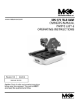
www.mkdiamond.com
Gas Powered
Concrete Saw
MK-24 Series Concrete Saw
OWNER’S MANUAL &
OPERATING INSTRUCTIONS
Part# 170954
170955
170956
170957
170958
Part# 170954
Revision 100
11.2014
Manual Part# 170954-OM
Caution: Read all safety and operating instructions
before using this equipment. This owner’s manual
MUST accompany the equipment at all times.
INTRODUCTION
Congratulations on your purchase of a MK-24 Series. We are certain that you will be pleased
with your purchase. MK Diamond takes pride in producing the finest construction power tools
and diamond blades in the industry.
Operated correctly, your MK-24 Series should provide you with years of service. In order to
help you, we have included this manual. This owners manual contains information necessary to
operate and maintain your MK-24 Series safely and correctly. Please take the time to familiarize
yourself with the MK-24 Series by reading and reviewing this manual.
Read and follow all safety, operating and maintenance instructions.
If you should have questions concerning your MK-24 Series, please feel free to call our friendly
customer service department at: 800 421-5830
Regards,
MK Diamond
NOTE THIS INFORMATION FOR FUTURE USE:
MODEL NUMBER:
SERIAL NUMBER:
PURCHASE PLACE:
PURCHASE DATE:
NOTE: For your (1) one year warranty to be effective, complete the warranty card
(including the Serial Number) and mail it in as soon as possible.
2
TABLE OF CONTENTS
SAFETY
Safety Messages
Damage Prevention Message
General Safety Precautions and Hazard Symbols
California Proposition 65 Message Safety Label Locations
Product Specifications
4
4
5
8
9
10
UNPACKING, TRANSPORT and ASSEMBLY
Unpacking
Contents
Transport
Assembly
11
11
12
13-15
SET-UP, OPERATION and SHUTDOWN
Set-Up
Operation
Shutdown
Cleanup
16-18
19-22
23
23
MAINTENANCE
Maintenance
24-30
ORDERING and RETURN INSTRUCTIONS
Ordering Information
50
Return Material Policy
50
Packaging Instructions
50
Authorized Service Centers
50
Contact Information
51
Warranty51
3
MK-24 Series
SAFETY
Safety precautions should be followed at all times when operating this equipment. Failure to read and
understand the Safety Precaution and Operating Instructions could result in injury to yourself and
others.
This Operation Manual has been developed to provide complete instructions for the safe and efficient
operation of the MK-24 Series. For additional instruction concerning engine operations and care refer
to the engine manufacturers instructions.
Before using this saw, ensure that the person operating the equipment has read and understands all
instructions in this manual.
Descriptions, illustrations, and photos are as accurate as possible at the time of publication. Photos
may include optional equipment or accessories and may not show all models covered by this manual.
SAFETY MESSAGE / ALERT SYMBOLS
A safety message alerts you to potential hazards that could hurt you or others. Each safety message is
preceded by a safety alert symbol (
) and one of three words: DANGER, WARNING, or CAUTION.
DANGER
You WILL be KILLED or SERIOUSLY INJURED if you do not follow directions.
WARNING
You CAN be KILLED or SERIOUSLY INJURED if you do not follow directions.
CAUTION
You CAN be INJURED if you do not follow directions. It may also be used
to alert against unsafe practices.
Each message tells you what the hazard is, what can happen, and what you can do to avoid or
reduce injury. Other important messages are preceded by the word NOTICE.
NOTICE
You can cause PROPERTY DAMAGE to your machine if you don’t follow directions.
The safety labels should be periodically inspected and cleaned by the user to maintain good legibility
at a safe viewing distance. If the label is worn, damaged or illegible, it should be replaced. Contact
MK Diamond or your dealer for replacement.
DAMAGE PREVENTION AND INFORMATION MESSAGES
A Damage Prevention Message is to inform the user of important information and/or instructions that
could lead to equipment or other property damage if not followed. Information messages convey
information that pertains to the equipment being used. Each message will be preceded by the word
note, as in the example below.
NOTE: Equipment and/or property damage may result if these instructions are not followed.
4
MK-24 Series
SAFETY
GENERAL SAFETY PRECAUTIONS AND HAZARD SYMBOLS
Safety Precautions
In order to prevent injury, the following safety precautions and symbols should be followed
at all times!
GENERAL SAFETY
DO NOT operate or service this equipment before reading this entire manual.
This equipment should not be operated by persons under 18 years of age.
NEVER operate this equipment when not feeling well due to fatigue, illness or taking medicine.
NEVER operate this equipment under the influence of drugs or alcohol.
Whenever necessary, replace nameplate, operation and safety decals when they become
difficult to read.
ALWAYS store equipment properly when it is not being used. Equipment should be stored
in a clean, dry location out of the reach of children.
KEEP GUARDS IN PLACE
In order to prevent injury, keep guards in place and in working order at all times.
EXPLOSIVE FUEL!
Gasoline is extremely flammable, its vapors can explode if ignited; store only in approved
containers, in well-ventilated, unoccupied buildings and away from sparks or flames. Do not
fill the fuel tank while the engine is running or hot. Spilled fuel could ignite if it contacts hot
parts or sparks from ignition. Do not start the engine near spilled fuel. Never use gasoline
as a cleaning agent. Never operate the machine in an explosive atmosphere.
LETHAL EXHAUST GASES
Engine exhaust gasses contain poisonous carbon monoxide, an odorless colorless gas
that can cause death if inhaled. Avoid inhaling exhaust fumes, and never run the engine
in a closed building or confined area.
ENGINE OVER-SPEED
((
))
Never tamper with the governor components or settings to increase the maximum speed of
the machine. Severe personal injury and/or equipment damage could result if the equipment is operated speeds above design maximum.
5
MK-24 Series
SAFETY
ACCIDENTAL STARTS
on
Before starting the engine, be sure the ON/OFF switch is in the “OFF” position to prevent
accidental starting. Place the ON/OFF switch in the OFF position before performing any
service operation.
ROTATING OR MOVING PARTS
Keep hands, feet, hair, and clothing away from all moving parts to prevent injury. Never
operate a power tool with shrouds or guards removed.
HOT PARTS
Engine components can become extremely hot from operation. To prevent severe burns, do
not touch these areas while the engine is running, or immediately after it is turned off. Never
operate the engine with heat shields removed.
ALWAYS USE SAFETY GLASSES
Safety glasses should always be worn when working around power tools. Everyday eyeglasses only have impact resistant lenses and may not prevent eye injury; they are NOT
safety glasses.
ALWAYS USE RESPIRATORY PROTECTION
Exhaust gases may be harmful if inhaled. Do not operate gas-powered equipment in
enclosed spaces. Respiratory protection should be worn when operating gas powered
equipment.
ALWAYS USE HEARING PROTECTION
To reduce the possibility of hearing loss, always use hearing protection when operating
equipment.
REMOVE ADJUSTING KEYS AND WRENCHES
Form a habit of checking to see that keys and adjusting wrenches are removed from the power tool
before it is turned on.
KEEP WORK AREA CLEAN
Cluttered work areas and benches invite accidents.
DO NOT USE IN DANGEROUS ENVIRONMENTS
Do not operate equipment in dangerous environments. Always keep the work area well lighted.
KEEP CHILDREN AWAY
All visitors and children should be kept a safe distance from work area.
MAKE WORKSHOP KID PROOF
Make the workshops kid proof by using padlocks, master switches or by removing starter keys.
6
MK-24 Series
SAFETY
DO NOT FORCE THE TOOL
A power tool will do a job better and safer operating at the rate for which it was designed.
USE THE RIGHT TOOL
Do not force a tool or an attachment, to do a job that it was not designed to do.
WEAR PROPER APPAREL
Do not wear loose clothing, gloves, neckties, rings, bracelets, or other jewelry that may be caught in
moving parts. Nonslip footwear is recommended. Wear protective hair covering to contain long hair.
SECURE WORK
Clamps or a vise should be used to hold work whenever practical. Keeping your hands free to operate a power tool is safer.
DO NOT OVERREACH
Keep proper footing and balance at all times by not overreaching.
MAINTAIN TOOLS WITH CARE
Keep tools sharp and clean for the best and safest performance. Always follow maintenance instructions for lubricating and when changing accessories.
SHUTDOWN TOOL
The saw should always be shutdown before servicing or when changing accessories such as blades,
bits, cutters, etc...
USE RECOMMENDED ACCESSORIES
Consult the owner’s manual for recommended accessories. Using improper accessories may increase the risk of personal or by-stander injury.
NEVER STAND ON THE TOOL
Serious injury could occur if a power tool is tipped, or if a cutting tool is unintentionally contacted.
NEVER LEAVE TOOL RUNNING UNATTENDED – TURN POWER OFF
Do not leave a tool until it comes to a complete stop. Always turn a power tool OFF when leaving the
work area, or, when a cut is finished.
CHECK FOR DAMAGED PARTS
Before using a power tool, check for damaged parts. A guard or any other part that is damaged
should be carefully checked to determine if it would operate properly and perform its intended function
safety. Always check moving parts for proper alignment or binding. Check for broken parts, mountings and all other conditions that may affect the operation of the power tool. A guard or any damaged
part should be properly repaired or replaced.
DIRECTION OF FEED
Always feed work into a blade or cutter against the direction of rotation. A blade or cutter should
always be installed such that rotation is in the direction of the arrow imprinted on the side of the blade
or cutter.
7
MK-24 Series
SAFETY
SILICA DUST WARNING
Grinding/cutting/drilling of masonry, concrete, metal and other materials with silica in their composition
may give off dust or mists containing crystalline silica. Silica is a basic component of sand, quartz,
brick clay, granite and numerous other minerals and rocks. Repeated and/or substantial inhalation of
airborne crystalline silica can cause serious or fatal respiratory diseases, including silicosis. In addition, California and some other authorities have listed respirable crystalline silica as a substance
known to cause cancer. When cutting such materials, always follow respiratory precautions.
Use appropriate NIOSH-approved respiratory protection where dust hazard may occur. Paper masks
or surgical masks without a NIOSH approval number are not recommended because they do little to
protect the worker. For more information about respirator programs, including what respirators have
received NIOSH approval as safe and effective, please visit the NIOSH website at:
http://www.cdc.gov/niosh/topics/respirators
Observe OSHA regulations for respirator use (29 C.F.R.§1910.134).
Visit http://www.osha.gov for more information.
CALIFORNIA PROPOSITION 65 MESSAGE
Some dust created by power sanding, sawing, grinding, drilling, and other construction activities contain chemicals known (to the State of California) to cause cancer, birth defects or other reproductive
harm. Some examples of these chemicals are:
• Lead, from lead-based paints
• Crystalline silica from bricks, cement and other masonry products
• Arsenic and chromium, from chemically treated lumber
For further information, consult the following sources:
http://www.osha.gov/dsg/topics/silicacrystalline/index.html
http://www.cdc.gov/niosh/docs/96-112/
http://oehha.ca.gov/prop65/law/P65law72003.html
http://www.dir.ca.gov/Title8/sub4.html
((
Your risk from these exposures varies depending on how often you do this type of work. To reduce
your exposure to these chemicals, work in a well-ventilated area, and work with approved safety
equipment, such as dust masks that are specially designed to filter out microscopic particles. Where
ON
)) extraction device is possible, it should be used. To achieve a high level of dust collecuse of a dust
tion, use an industrial vacuum cleaner.
WARNING
Sawing and drilling generate dust. Excessive airborne particles may cause irritation to eyes, skin and
respiratory tract. To avoid breathing impairment, always employ dust controls and protection suitable
to the material being sawed or drilled; See OSHA (29 CFR Part 1910.1200).
8
MK-24 Series
SAFETY
OPERATION & SAFETY DECALS
The MK-24 Series Concrete Saw is equipped with a number of safety decals. These decals are provided for operator safety and maintenance information. Should any of these operation or safety decals become unreadable, replacements can be obtained by calling (800) 262-1575.
! CAUTION
! WARNING
! WARNING
DO NOT operate
this equipment
before reading
the owners’
manual!
C
B
! DANGER
A
In the event of
blade failure,
replace blade
guard
immediately.
E
! CAUTION
FOR INFORMATION ON
! WARNING
Keep
hands and
feet clear.
PLEASE CALL
1-800-474-5594
K
J
! NOTICE
! WARNING
Overtensioning of belts
will result in premature
crank and/or bearing failure.
Handle bar NOT a lifting point.
! CAUTION
SERVICE OR
WARRANTY
I
H
G
F
Accidental start hazard.
Disconnect spark plug
prior to servicing.
DO NOT
touch hot
surface.
When refueling
stop engine and
allow to cool.
DO NOT overfill
tank.
Lethal exhaust
gases. Use only
in well ventilated
areas. DO NOT
use indoors.
! CAUTION
D
! WARNING
DANGER
The exhaust from this product
contains chemicals known to
the State of California to cause
cancer, birth defects or other
reproductive harm.
! WARNING
DO NOT
operate without
guards in place.
Grinding/cutting/drilling of masonry, concrete, metal and other materials with silica in
their composition may give off dust or mists containing crystalline silica. Silica is a basic
component of sand, quartz, brick clay, granite and numerous other minerals and rocks.
Repeated and/or substantial inhalation of airborne crystalline silica can cause serious
or fatal respiratory diseases, including silicosis. In addition, California and some other
authorities have listed respirable crystalline silica as a substance known to cause cancer.
For manuals and parts
lists scan the QR code
with your smart phone
O
L
M
Concrete Saw Warning Label Sheet Part# 166009
K
P
N
C
L
H
Location
Frame
B Frame
C Shaft Cover
D Blade Guard
E Gas Tank/Top
F Gas Tank/Top
G Gas Tank/Top
H Belt Guard
I
Belt Guard
J Frame/Back
K Frame/Front Belt Guard
L Handle
M Belt Guard
N Blade Guard
O Frame Back
P Console
A
C
A
K
M
B
I
N
D
G
F
E
9
J
O
Description
Read Manual
Proposition 65, Dust Warning
Guards in Place
Replace Blade Guard
Exhaust/Cancer
Lethal Exhaust
Refueling
Hot Surface
Accidental Start
Service (Not Shown)
Hand & Feet Clear
Lifting Point
Overtensioning Belts
Belt Drive and Blade Flanges
QR Code for Manuals
Machinery Hazard
MK-24 Series
PRODUCT SPECIFICATION
PRODUCT SPECIFICATIONS
The MK-24 Series is a versatile gas powered Concrete Saw. Operated and used according to this
manual, the MK-24 Series will provide years of dependable service.
General Description
The MK-24 Series is engineered as a portable concrete saw powered by a Honda or Subaru gas engine or a propane engine by Kohler or Subaru. The saw is capable of 9-3/4” depth of cut with an 24”
blade.
Motor and Weight Specifications
Motor and Weight specifications for the MK-24 Series are listed below.
Arbor Size
1" (25 mm)
L x W x H (inches) 49" x 25" x 45"
1,245 x 635 x 1,143
L x W x H (mm)
Includes
Lifting Bail
Model
MK-2420HSP
MK-2424HSP
MK-2422SSP
MK-2425KSP
MK-2425SSP
Engine
Honda (Gas)
Honda (Gas)
Subaru (Gas)
Kohler (Propane)
Subaru (Propane)
Starter
Electric
Electric
Electric
Electric
Electric
Power
GX630 V-Twin*
GX690 V-Twin*
EH65*
EH72LP*
CH730LPG*
Blade Capacity
24" (610 mm)
24" (610 mm)
24" (610 mm)
24" (610 mm)
24" (610 mm)
Depth of Cut
9-3/4" (248 mm)
9-3/4" (248 mm)
9-3/4" (248 mm)
9-3/4" (248 mm)
9-3/4" (248 mm)
Weight
398 lbs. (181 kg)
404 lbs. (183 kg)
404 lbs. (183 kg)
425 lbs. (193 kg)
423 lbs. (192 kg)
Part#
170954
170955
170956
170957
170958
*Engine power ratings are calculated by the individual engine manufacturer and the rating method may vary among engine manufacturers. MK Diamond Products makes no claim,
representation or warranty as to the power rating of the engine on this equipment and disclaims any responsibility or liability of any kind whatsoever with respect to the accuracy or the
engine power rating. Users are advised to consult the engine manufacturer’s owners manual and website for specific information regarding the engine power rating.
Blade
The MK-24 Series uses a 24” diameter diamond blade.
Concrete Saw Usage
The MK-24 Series is designed to cut various grades of concrete surfaces.
10
MK-24 Series
UNPACKING
MK-24 Series Series Features
• One-piece box construction chassis made from 3/16” hot-rolled steel
• Powder-coated chassis resists peeling and corrosion
• 12-gauge hinged blade guard
• Ride-on-the-blade water distribution system supplies water to both sides of blade
• Blade guard mounts on both left- or right-hand side of saw and cuts within 2” of wall or curb
• Heavy-duty blade shaft supported by two 1-3/16”, self-aligning pillow blockbearings
• Depth control assembly engineered for smooth, controlled blade insertion
• Built-in tach/hour meter
• Depth feed gauge indicator
• Heavy-duty hydro static transmission with variable speed drive
• Durable 8” x 2-1/4” non-slip rubber wheels with maintenance-free hubs & roller bearings
• Forward and reverse travel speed: 0-80’ minute
UNPACKING
Your saw has been shipped from the factory thoroughly inspected. Only minimal assembly and
service is required. Check each item, making certain all items are accounted for and in good visual
condition before discarding any packing materials. If there are any missing or damaged parts call MK
Diamond Customer Service at 800-421-5830.
WARNING
Never start engine until all initial servicing and set up steps are completed according to this operations manual and engine manual. Read and familiarize yourself
with all controls and features of the saw before beginning operations.
Remove the saw from the pallet and place it on a flat surface. Two people are required to lift saw.
CONTENTS
In the containers, you will find one (1) MK-24 Series Saw, one (1) Blade Nut Wrench, one (1) Handlebar, two (2) Handlebar Bolts and Washers, one (1) Pointer, one (1) MK-24 Series Owner’s Manual,
one (1) Engine Owners Manual, one (1) Warranty Card.
MK-24 Series
Saw
www.mkdiamond.com
1 Blade Nut
Wrench
Handlebar
Engine Manual
Warranty
Card
MK-24 Series
OWNER’S MANUAL &
OPERATING INSTRUCTIONS
Gas Powered
Concrete Saw
Revision 100
11.2014
Manual Part# 170954-OM
Caution: Read all safety and operating instructions
before using this equipment. This owner’s manual
MUST accompany the equipment at all times.
MK-24 Series
Owner’s Manual
11
Handlebar
Bolts and Washers
Pointer
MK-24 Series
TRANSPORT
TRANSPORT
CAUTION
1. The MK-24 Series weighs approximately two hundred and thirty-five (235
pounds), use care when transporting.
2. Two people are required to lift and transport the MK-24 Series.
DESCRIPTION OF CONTROLS
1
2
9
3
7
4
5
10
6
8
1. 2. 3. 4.
5.
6.
7. 8. 9.
10.
The Depth Control Wheel raises the blade when rotated clockwise, and lowers the blade when rotated counterclockwise.
The keyed ignition switch turns clockwise to the on and start positions. The engine turns over with the switch in the start position. Release the key after the engine starts.
When the engine is running, the Tach/Hour Meter display will indicate the engines RPM. When the engine is shut off, the display will switch to run time, initially in minutes, and then switching to hours after the first hour of operation.
The Transmission Speed Lever moves the saw forward by pushing the lever away from the operator and moves the saw in reverse by pulling the lever toward the operator. Always place this control in central neutral position before using the engage/disengage lever or starting or stopping the engine.
The Throttle control increases engine rpm from slow (idle) at the bottom, to fast
(full rpm) at the top.
Depth Gauge should be adjusted to zero when setting up the saw.
Use water hose bibb for wetting cutting. After connecting hose, turn on the water at the source and use Water Control Lever to control flow of water to the blade. Be sure that both sides of the blade are getting adequate flow of water.
Water Control Lever is off in the vertical position and fully on in the horizontal position. It may be placed at in between settings to regulate the water flow.
The Transmission Engage/Disengage Lever is engaged in the full down position.
The Choke is located on the back panel for convenient cold starting.
12
MK-24 Series
ASSEMBLY
Follow the assembly instructions to prepare your saw for operation.
Handlebar Assembly
(A)
Locate the threaded holes on
both sides of the handlebar.
(B)
Align the handlebar with the
holes on both sides of the frame at
the desired height.
(C)
Install one Washer onto each bolt.
Install bolt through the Handlebar
and into the holes and tighten.
Filling Oil Reservoir
NOTE:
The engine is shipped with no oil in the crankcase. Refer to the engine manual for details on the type and amount of oil required.
To fill the crankcase with oil, place the engine level. In order for this to be accomplished
the blade must not be installed, and the depth adjustment must be down (until the engine is level).
NOTE:
The engine and oil must be warm and your saw must
be on level ground to get an accurate oil level reading.
(A)
Verify the Oil Drain Cap is installed
onto the Oil Drain Line and is tight.
Refer to Engine Manual for details.
13
MK-24 Series
ASSEMBLY
Hydro-Static Transmission
The Hydro-Static Transmission is factory filled with fluid having a viscosity equivalent to SAE 20 W
20.
NOTICE
Do not overfill the expansion tank. Notice that the full level line is near the
bottom of the expansion tank. Over filling will result in rupturing the seals
on the hydromatic transmission and subsequent mechanical damage.
(A)
Check the oil level on the expansion
tank to ensure that the transmission
has adequate fluid.
Battery Preparation
The 12 volt battery is shipped wet and charged. Connect the battery leads according to the following
steps to ensure that power is provided to the engines electric starter.
(A)
Remove the front tower panel to obtain access to the battery terminals.
WARNING
(B)
Connect the positive (+) battery
cable to the positive battery terminal.
Connect the negative battery cable
to the negative terminal. Tighten
the cap screws and nuts securely
to assure proper electrical contact.
Replace panel.
When tightening the positive (+) battery cable end, do not contact the negative (-) battery terminal with the wrench or other metallic objects. This could
cause an electrical short and electrical sparking or an explosion of the battery.
Be careful not to connect the battery in reverse polarity, as this will short circuit
the battery charging system causing the fuse on the engine to become damaged, and also possibly resulting in an explosion of the battery.
14
MK-24 Series
ASSEMBLY
Diamond Blade Installation
NOTE:
1. When installing the blade retaining-bolt, ensure the threads of the bolt are aligned with the threads of the drive shaft so as not to “cross-thread” the bolt.
2. When installing the blade ensure that the blade shaft and flanges are free from dirt and all foreign material before mounting blade on the blade shaft. Tightening a blade against an uneven surface can cause fracture or cause the blade to run out of alignment.
3. Blade shaft threads are left-handed on the right side of the saw and right-hand on the left of the saw.
(A)
Open the Blade Guard Cover.
Locate the Blade Shaft Nut and the
Outer Flange.
(B)
Loosen the Blade Shaft Nut while
holding the Shaft Wrench steady.
(C)
Remove the Blade Nut and Outer
Flange.
(D)
Install the Diamond Blade onto the
Blade Shaft and Drive Pin. Ensure
directional arrow on the blade indicates proper rotational direction.
(E)
Install the Outer Flange. Verify the
drive pin is seated; it must project
through the hole in the blade and into
the flange.
(F)
Install the Blade Shaft Nut.
WARNING Do not operate the saw without the proper
Blade Guard covering. Ensure that the blade
exposure does not exceed 180 degrees during
operation.
DO NOT use woodcutting, or carbide blades
on this machine! Use ONLY Diamond
blades on machine.
(G)
Tighten Blade Shaft Nut holding
the Blade Shaft steady. Lower and
close Blade Guard.
NOTE:
15
Raise the blade as high as possible when maneuvering so that the blade will not strike the
pavement. The blade is spinning whenever the
saw is running.
MK-24 Series
SeT-UP
Filling Fuel Tank
WARNING
1. Gasoline is highly flammable and explosive. You can be burned or seriously injured when handling fuel.
2. To fuel, stop engine if running, and allow it to cool.
3. Fuel in a well-ventilated area.
4. Keep gasoline away from appliance pilot lights, barbeques, electric appliances,
power tools, etc.
5. Wipe up spills immediately. Do not start engine until spill is dry.
6. When filling the fuel tank do not overfill. Always leave enough area for
expansion due to environmental heating.
NOTE:
1. Fuel can damage paint and plastic. Be careful not to spill fuel when filling the fuel tank. Damage caused by spilled fuel IS NOT covered under the warranty.
2. DO NOT use stale or contaminated gasoline, or an oil/gasoline mixture.
1 inch (25mm)
from throat
Maximum Fuel
Level
(A)
Remove the Fuel Cap.
(B)
Ensure fuel level is 1” below the
throat of the Fuel Tank.
Front Pointer Alignment
The Front Pointer is set in line at the factory. However, the pointer should be checked for proper
alignment with the blade after every use.
(A)
Using a straight edge, carefully mark a line 12 feet long on
a smooth level concrete surface.
Place Saw parallel to line; lower
Blade and center it over the line.
(B)
With the Blade centered over the
line and the Saw Frame parallel
to the line, lower the front Pointer
assembly and position the pointer
over the line.
16
(C)
Adjust the Pointer in or out if the
orange wheel is off the line by loosening the thumbscrew on the end of
pointer. Align orange wheel with line
and tighten thumbscrew. Roll saw
along the entire length of the line to
ensure proper alignment.
MK-24 Series
SeT-UP
Pre-Start Inspection
The pre-start inspection should be performed before beginning any job.
(A)
Inspect Blade for damage for
cracks and wear, replace if necessary. Verify the Blade is correct for the material being cut.
Proper Oil Level
(B)
Inspect Engine for leaks.
Make sure surfaces are clean
and unobstructed.
(C)
Inspect the saw for general damage and/or loose hardware. Check
that the equipment covers and
guards are in place and securely
fastened.
1 inch (25mm)
from throat
Maximum Fuel
Level
Low Level
(D)
Check for proper oil level.
Refer to Engine Manual for details.
(E)
Ensure fuel level is 1” below the
throat of the Fuel Tank.
(F)
Check the Air Filter for
cleanliness. Refer to Engine Manual
for details.
WARNING
• NEVER disconnect any “emergency or safety devices”. These devices are intended for operator s afety. Disconnection of these devices can cause severe injury, bodily harm or even death! Disconnection of any of these devices will void all warranties.
• Unauthorized equipment modifications will void all warranties. Manufacturer does not
assume responsibility for any accident due to equipment modifications.
• NEVER use accessories or attachments, which are not recommended by MK Diamond for this equipment. Damage to the equipment and/or injury to user may result.
17
MK-24 Series
SeT-UP
Adjusting Depth of Cut Gauge
(A)
Turn Crank Wheel until Blade
touches the ground.
(B)
Turn the Depth Gauge Indicator
dial clockwise until it reads zero.
BLADE SPEED AND THROTTLE SETTING
((
))
Since diamond blades cut best at specific rim-speeds, blades of different diameters
must be turned at different blade shaft rpm’s.
The MK-2013/14 will run either a 16” or 18” blade and the MK-2020/24/22 HSP will run
a 16” through 20” blade.
Safe, efficient, economical cutting performance will occur at the engine rpm (as read on
the tachometer) stipulated on the following chart.
Blade Diameter
14”
16”
18”
20”
set engine rpm to*
full throttle (3500)
3200-full throttle
2850-3300
2550-3000
The MK-24 Series engine shaft to blade shaft ratio is 1:895.
WARNING
Operating saw blades at rotational speeds greater than those recommended
by the manufacturer can cause blade damage and possibly subsequent personal injury.
Never exceed 3600 rpm blade shaft speed.
* The MK-24 Series, it is possible to cause overspeeding of the blade at throttle
settings above those stipulated on the above chart; DO NOT EXCEED THESE
ENGINE RPM SETTINGS!
18
MK-24 Series
OPERATION
Standard Operation
The MK-24 Series is intended for industrial applications and operated by experienced professionals.
The operator must be aware of the machine’s capabilities and limitations. It is the operators responsibility to use this machine under safe working conditions and conform with federal, state and local
codes or regulations pertaining to safety, air, pollution, noise etc...
CAUTION
Prior to operation of this machine the operator must determine the existence and
location of any subsurface features that may be hazardous or could damage the
equipment, (i.e. electric cable, natural gas line etc...)
WARNING
Be sure blade is unobstructed and not resting on ground.
Be sure hands and feet are clear of blade.
WARNING
Carbon monoxide gas is toxic, breathing it can cause unconsciousness
and/or death. Ensure that the space is adequately ventilated.
Avoid any areas or actions that expose you to carbon monoxide.
NOTICE
If the saw should stall for any reason, raise the blade out of the cut before
restarting the engine.
Read the engine instructions manual before starting saw.
NOTICE
DO NOT crank engine for more than 30 seconds at a time. If engine fails to
start, wait about 2 minutes between cranking periods to prevent starter from
overheating.
NOTICE
Allow engine to warm up at least 3 minutes before applying load. When engine
is warm, throttle may be used out to maximum position. Special precautions
should be taken during the break-in period as specified by the Engine Manual.
(A)
Use the Depth Control Wheel to
raise the blade clear of the floor.
(B)
Attach the cooling supply hose
to the Cooling Inlet, if wet cutting.
19
(C)
Layout and mark the area to be
cut using a chalk-line. Align Pointer
and Blade to chalk-line.
MK-24 Series
OPERATION
(D)
Place Transmission Speed
Lever in Neutral.
(E)
Verify Neutral Engagement Handle
is down, in Neutral. Choke engine
as required for cold starting.
(F)
Push Engine Throttle Handle up
half-way.
(G)
Start engine by rotating Ignition
Switch to the right.
(H)
For Wet Cutting, open Cooling
Supply Valve. Verify proper cooling
flow and adjust the water flow on
the Blade to a desired amount.
(I)
Move the throttle all the way forward to “Fast” position.
NOTE:
Perform the cut using only enough pressure to follow the original marked line. The saw has a
natural tendency to pull towards the side on which the blade is mounted. To assure straight line
cutting, apply pressure to the appropriate handle. If excessive pressure is required reduce the
forward speed of the saw. Driving the saw too fast while cutting may cause the front wheels
to lift causing the blade to cut at uneven depths. Do not attempt to steer the saw. Sudden and
severe corrections can cause the blade to be damaged or broken.
(J)
Slowly lower the Blade until the
desired level is reached and begin
the cut.
(K)
When the cut is complete, raise
the Blade completely out of the cut
by turning Depth Control Wheel
counter-clockwise.
20
(L)
Close Cooling Supply Valve.
MK-24 Series
OPERATION
NOTE:
Do not turn off engine while
at full throttle.
NOTICE
(M)
Move the Throttle Lever to lower
blade speed.
(N)
Turn off engine by rotating
Ignition Switch to off position.
If the engine has been running
hard and is hot do not shut engine off abruptly. Cool engine by
removing load and allowing engine to run idle for 3 to 5 minutes.
step Cutting
1. Follow general instructions outlined in the section Standard Operation on page 19.
2. When deep sawing (more than 4”) or concrete with hard aggregate, sawing to full depth in
several cuts should be made in incremental steps of 1-1/2 to 2 inches until the desired depth of cut is reached. In softer aggregates or asphalt, it may be possible to saw full depth in two passes.
3. Gradually move the speed control lever forward to increase the cutting speed. If the blade stalls in the cut (which can happen when deep sawing) immediately raise blade from cut. If not done at once, the belts will spin freely and burn. Check belts for proper tension and continue sawing at a slower rate of speed.
4. On final pass, lower the blade until it hits the sub-base (sandy color will appear in the water being discharged from the cut). Raise blade approximately 1/2” from bottom. The sand and gravel
particles of the sub-base may cause premature wear or damage to the saw blade.
5. It is common, on the final pass of the cut, for pavement to wedge blade, particularly on a hot day.
When this happens, immediately stop engine. If the blade is wedged, remove the Blade Shaft Bolt and Outside Collar and move the saw away from the blade. To remove a wedged blade from the concrete, use a jack hammer and carefully chip out concrete around the blade. (Pounding or
twisting the blade may cause severe damage).
6. Go slowly with a new blade until it “opens up” that is, until you can see and feel the diamonds.
7. Small corrections can be made by leaning on handles.
Deep sawing is very hard on saws and blades. Experienced operators soon get a “feel” for the saw and are constantly on guard to slow down when they hit excessive steel or hard aggregate.
Dry Cutting
NOTE:
1. Ensure the blade you are using is clearly marked for dry cutting.
2. Check the condition of the air filter at least every four hours of operation.
Refer to Engine Manual for details.
Airflow helps to cool the blade during dry cutting. Cutting too deep with one pass, or exerting excessive forward or side pressure can be dangerous and cause damage. Step cut in increments of 2
inches or less, for best results. Thinner blades are especially advantageous when cutting dry.
21
MK-24 Series
OPERATION
Blade GUARD Repositioning
WARNING Do not operate saw with any guards removed. Turn master engine switch to off
position to avoid accidental starts when removing guards.
(A)
Remove Diamond Blade.
(B)
Remove the Cooling Transfer
Hose from the Blade Guard by
pressing the quick release.
(C)
Locate the four Blade Guard Retaining Bolts.
(D)
Remove the Blade Guard
Retaining Bolts and remove the
Blade Guard.
(E)
Locate the Blade Shaft Cover
Retaining Bolts.
(F)
Remove the Blade Shaft Cover
Retaining Bolts and the Blade
Shaft Cover.
(G)
Install the Blade Guard on the
opposite side of the saw..
(H)
Install Diamond Blade
(I)
Install the Cooling Transfer Hose
to the Blade Guard.
22
MK-24 Series
CLEANUP
(J)
Install the Blade Shaft Cover.
(K)
Remove the Pointer.
Emergency Engine Shutdown
(A)
Place Engine Master Switch in the
OFF position.
(L)
Install the Pointer on the opposite
side, next to Blade Guard.
(See Front Pointer alignment Page
16)
(B)
Move the Throttle Lever to lower
blade speed. Place Fuel Valve in
the OFF position.
cleanup
Caution
NOTE:
Engine parts are extremely hot following use, allow engine to cool 1/2-hour before
cleaning. Use care during cleanup to avoid injury.
1. To extend operating life, the Concrete Saw should be cleaned following
every use.
2. Using a garden hose or pressure washer is not advised as it can force water
into the air cleaner or muffler opening. Steam cleaning is the preferred
method of cleaning.
3. Use care when cleaning around electrical components.
23
MK-24 Series
MAINTENANCE
(A)
Verify the engine is off and cool before beginning to clean. Clean the
saw with soap and water.
(B)
Clean water system outlets,
including water tubes in blade
guard.
(C)
Clean the remainder of the exterior
surface (except the engine).
Maintenance schedule
Item should be performed at every indicated hour(s) or interval period whichever goes first.
Maintenance Schedule
Air Filter
Maintenance
Operation
Daily
25 Hours
or Weekly
100 Hours or
Seasonal
Every 4 Hours
When Dry Cutting
Check
Every 8 Hours
When Wet Cutting
•
Change Air Filter
•
Hydrostatic
Check Oil
Transmission/Reservoir
Mainframe
Blade Shaft
Bearings
Lube Blade Shaft
Bearings at end of
Operations
Pivot Bearings
•
•
Chain Drive
Transmission
Control Assemblies
Battery
•
•
Adjust Tension
•
Replace
V-Belts
•
Battery
Check Water Level
Engine
•
Definitive information on engine maintenance is contained in the Engine Manual
provided separately. Perform all maintenance procedures as recommended by the
engine manual.
24
•
MK-24 Series
MAINTENANCE
MAINTENANCE SAFETY
•
•
•
•
Always turn the master engine switch to the off position.
NEVER lubricate components or attempt service on a running machine.
Keep the machinery in proper running condition.
Fix damage to the machine immediately and always replace broken parts, or missing decals.
New Maintenance
Perform the following after initial purchase and operation of the saw.
(A)
Change engine oil after
first month or first 20 operating
hours (See Engine Manual).
(B)
Check and adjust tension on
all belts following first
48 hours of operation.
Maintenance Following Use
The following maintenance should be performed following each use.
(A)
Shut down the Engine. Let saw cool
before proceeding.
(B)
Check Air Filter
(See Engine Manual).
25
(C)
Lubricate the Grease Fitting on the
Blade Shaft.
MK-24 Series
(D)
Lubricate the zerk fitting on each
wheel.
MAINTENANCE
(E)
Lubricate the Cooling
Supply Valve.
(F)
Verify the tightness of all bolts and
screws. Clean the saw (except the
engine) with soap and water.
Weekly (50 hours) and Monthly (200 hours)
The following should be performed monthly. Items should be lubricated using waterproof grease.
(A)
Change engine oil every 100 hours.
Refer to Engine Manual for details.
(B)
Lubricate the Blade Shaft Bearings
(Monthly).
(C)
Clean engine Air Filter weekly and
replace monthly. Refer to Engine
Manual for details.
(D)
Clean Spark Plug Weekly and readjust Spark Plug monthly. Refer to
Engine Manual for details.
(E)
Clean and lubricate the Blade Shaft.
(F)
Clean and lubricate the Blade Retaining Bolt.
NOTE:
Definitive information on engine maintenance is contained in the engine manual
provided separately. Perform all maintenance procedures as recommended by the
Engine Manual.
26
MK-24 Series
MAINTENANCE
500 Hours and 1000 Hour Maintenance
Perform the following maintenance every 500 hours.
(A)
Replace Spark Plug. Refer to Engine Manual for details.
(B)
Have Authorized Repair Shop perform 500-hour maintenance.
Yearly and Two-Year Maintenance
Perform the following maintenance every year.
(A)
Inspect belts for proper tension
and wear.
27
(C)
Have Authorized Repair Shop perform 1000-hour maintenance.
MK-24 Series
MAINTENANCE
Check Fuel Level
For all Engine related maintenance and troubleshooting refer to the Engine Manual.
WARNING 1.
2.
3.
4.
5.
NOTE:
Gasoline is highly flammable and explosive. You can be burned or seriously injured when handling fuel.
To fuel, stop engine if running and allow it to cool.
Refuel in a well-ventilated area.
Keep gasoline away from appliance pilot lights, barbeques, electric appliances, power tools, etc.
Wipe up spills immediately.
1. Fuel can damage paint and plastic. Be careful not to spill fuel when filling the fuel tank. Damage caused by spilled fuel IS NOT covered under the warranty.
2. DO NOT use stale or contaminated gasoline or an oil/gasoline mixture.
1 inch (25mm)
from throat
Maximum
Fuel Level
(A)
Remove the Fuel Cap. Refer to
Engine Manual for details.
(B)
Ensure fuel level is 1” below the
throat of the Fuel Tank.
Engine Maintenance
Engine maintenance and adjustment is necessary to keep the saw in good operation condition. Maintenance operations include oil changes, filter changes, air cleaner, spark plug, fuel filter etc...Perform
all maintenance procedures as recommended by the Honda, Vanguard, Kohler or Subaru engine
manual provided separately.
(A)
Remove the Diamond Blade.
(B)
Lower the MK-24 Series to
its lowest position.
28
(C)
Free the Oil Drain Line.
Place a catch basin below the
Oil Drain Line. Remove the Drain
Cap to drain oil completely. Refer
to Engine Manual for details.
MK-24 Series
MAINTENANCE
Engine Air Filter Inspection, Cleaning and Replacement
(A)
Clean the Air Filter. Refer to
Engine Manual for details.
Spark Plug Adjustments and Replacement
For all Engine related maintenance and troubleshooting refer to the Engine Manual.
Caution
DO NOT work around the engine while hot.
(A)
When installing the Spark Plug,
ensure the threads are aligned with
the threads in the engine so as not to
“cross-thread” the plug.
Electrical System
A fuse protects the battery charging circuit. The fuse and the battery are the only user serviceable
parts of the electrical system, a short circuit or a battery connected in reverse polarity will blow the
fuse. Refer to the Engine Manual for the location and type of fuse. The fuse on the Engine is located
between the starter solenoid and the engine, and is rated at 30 amps.
Caution
If the fuse blows, determine the cause of the problem before resuming operations.
29
MK-24 Series
MAINTENANCE
Battery
Check water level weekly. Add distilled water if necessary. Check terminal cables and remove any deposits. Remove the battery for recharging and follow the instructions for recharging. Damage can result
to the battery and electrical system if the battery is charged or installed in reverse polarity. Make sure
that the negative terminal is connected to ground.
Remove and install battery as per instructions in Assembly Section of this manual. Be careful not to
contact metal while loosening positive terminal with tools.
Caution
Observe all battery precautions as outlined in the Assembly Section of this manual.
Belt Adjustment and Replacement
This machine is equipped with two heavy duty V-belts which are
tensioned properly at the factory. These must be re-tensioned after
the first half day of operation and periodically thereafter. Adjust to the
original tension as set at the factory, which is approximately 1/4 inch
of defection of the center of the belt halfway between the pulley on the
motor and the pulley on the blade shaft.
To adjust belt tension, first remove the belt guard. With the belt guard
removed, loosen motor mount bolts. Loosen the lock nut and adjust
set bolt on the motor tension adjuster until the required belt tension is
achieved.
Retighten the motor mounting bolts.
The two most common causes of misalignment are shown in the drawings.
A. the engine drive shaft and the blade shaft are not parallel.
B. the pulleys are not located properly on the shafts.
Never make adjustments to belts or pulleys while engine is running.
Caution
DO NOT OVER TENSION as damage to belts and bearings
may occur. Belts that are too loose may slip, resulting in short
life and loss of power to the blade shaft. If any belts are worn or
damaged, replace the complete set.
The motor mounting plate must be maintained parallel to the
frame. Make sure all lock nuts are tightened and retighten the
bracket bolts.
30
(A)
(B)
NOTE:
Gap between steel
straight edge and
sheave.
NOTES
31
MK-24 Series
ORDERING & RETURN
ORDERING INFORMATION
You may order MK Diamond products through your local MK Diamond distributor or, you may order
direct from MK Diamond.
When ordering direct from MK Diamond, please have the following information ready before calling:
• The Model Number of the saw
• The Serial Number of the saw
• Where the saw was purchased and when
• The Part Number for the part(s) being ordered
• The Part Description for the part(s) being ordered
NOTE: There is a $25.00 minimum order when ordering direct from MK Diamond. A $6.00 charge will
be added to orders having a net billing value under $50.00. All purchases must be made using VISA,
MasterCard or American Express.
All parts may be ordered by calling toll free to – 800 421-5830 or 310 539-5221 and asking for
Customer Service. For technical questions, call – 800 474-5594.
RETURN MATERIALS POLICY
To expedite the service relative to the return of a product purchased through MK Diamond, please
observe the following:
NOTE: When returning all items, they must have been purchased within the previous twelve (12)
months.
• Have the Model Number of the saw
• Have the Serial Number of the saw
• Have the location of where the saw was purchased
• Have the date when the saw was purchased
• Contact Customer Service for approval to return the item(s)
• Obtain a Returned Goods Number (RGA) authorizing the return
• Follow the packaging instructions in the following section
• Ensure your item(s) are prepaid to the destination
For returned items, call toll free to – 800 421-5830 or 310 539-5221 and ask for Customer Service.
For technical questions, call – 800 474-5594 or 310 257-2845.
PACKAGING INSTRUCTIONS
• Remove the Cutting Head and Support Angle Assembly
• Dry the saw before shipping
• When packing, include the following: Saw, Diamond Blade, and Blade Guard
Assembly and Adjustable Cutting Guide (Other Accessories are not required)
• Package the unit in its original container or one of comparable size (do not ship the unit partially exposed)
• Ensure all parts are secured in the packaging to prevent moving
AUTHORIZED SERVICE CENTERS
For quicker repair time, you may contact MK Diamond Customer Service, toll free, at 800 421-5830
or 310 539-5221 for the Authorized Service Center closest too you or visit our web site at
www.mkdiamond.com. For technical questions, call – 800 474-5594.
32
MK-24 Series
WARRANTY
CONTACT:
Please contact MK Diamond Products, Inc. Customer Service Department with any questions you
might have regarding distributors, parts or service.
Telephone: (800) 421-5830
Fax: (310) 539-5158
E-mail: [email protected]
Customer Service Hours: Monday through Friday, 6AM-4PM PST
MK Diamond Products, Inc.
1315 Storm Parkway
Torrance, CA 90501
MK DIAMOND PRODUCTS, INC. LIMITED WARRANTY
MK DIAMOND PRODUCTS, INC. will guarantee every machine they build, to be free from defects in
material and workmanship for (1) one year from date of purchase. The obligation of MK DIAMOND
PRODUCTS, INC. under this warranty is limited to the repair or replacement of any parts which,
under normal use, prove to be defective in material or workmanship. The parts involved or the unit
in question should be returned to MK DIAMOND PRODUCTS, INC. or to a point designated by us,
transportation prepaid.
This warranty does not obligate us to bear the cost of labor or transportation charges in connection
with replacement or repair of defective parts. Likewise, it shall NOT apply to any unit which has been
subjected to misuse, neglect or accident. This warranty does NOT apply to any machine which has
been repaired or altered outside our factory.
This warranty does NOT obligate MK DIAMOND PRODUCTS, INC., with respect to items not of our
manufacture, such as engines, motors, hydraulics, etc., which are subject to their own guarantees and
warranties.
We shall in no event be liable for consequential damages or contingent liabilities arising out of failure
of any equipment or parts to operate properly.
© COPYRIGHT 2012, MK DIAMOND PRODUCTS, INC. ALL RIGHTS RESERVED.
The MK Diamond logo is a registered trademark of MK Diamond Products, Inc. and may not be used,
reproduced, or altered without written permission. All other trademarks are the property of their respective owners and used with permission.
MK Diamond may have patents, patent applications, trade marks, copyrights of other intellectual
property right covering this product in this document.
This manual MUST accompany the equipment at all times. This manual is considered a permanent
part of the equipment and should remain with the unit if resold.
The information and specifications included in this publication were in effect at the time of approval for
printing.
33
NOTES
34
NOTES
35
MK-24 Series Concrete Saw
OWNER’S MANUAL & OPERATING INSTRUCTIONS
MK Diamond Products, Inc.
1315 Storm Parkway
Torrance, CA 90501
Toll-Free: (800) 421-5830
Phone: (310) 539-5221
Fax: (310) 539-5158
www.mkdiamond.com