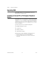
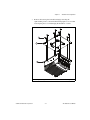
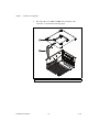
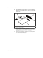
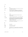
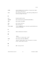
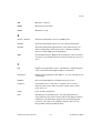
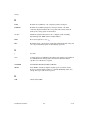
1
NI 3100/3110 User Manual NI 3100/3110 User Manual May 2009 372273A-01 Support Worldwide Technical Support and Product Information ni.com National Instruments Corporate Headquarters 11500 North Mopac Expressway Austin, Texas 78759-3504 USA Tel: 512 683 0100 Worldwide Offices Australia 1800 300 800, Austria 43 662 457990-0, Belgium 32 (0) 2 757 0020, Brazil 55 11 3262 3599, Canada 800 433 3488, China 86 21 5050 9800, Czech Republic 420 224 235 774, Denmark 45 45 76 26 00, Finland 358 (0) 9 725 72511, France 01 57 66 24 24, Germany 49 89 7413130, India 91 80 41190000, Israel 972 3 6393737, Italy 39 02 41309277, Japan 0120-527196, Korea 82 02 3451 3400, Lebanon 961 (0) 1 33 28 28, Malaysia 1800 887710, Mexico 01 800 010 0793, Netherlands 31 (0) 348 433 466, New Zealand 0800 553 322, Norway 47 (0) 66 90 76 60, Poland 48 22 328 90 10, Portugal 351 210 311 210, Russia 7 495 783 6851, Singapore 1800 226 5886, Slovenia 386 3 425 42 00, South Africa 27 0 11 805 8197, Spain 34 91 640 0085, Sweden 46 (0) 8 587 895 00, Switzerland 41 56 2005151, Taiwan 886 02 2377 2222, Thailand 662 278 6777, Turkey 90 212 279 3031, United Kingdom 44 (0) 1635 523545 For further support information, refer to the Technical Support and Professional Services appendix. To comment on National Instruments documentation, refer to the National Instruments Web site at ni.com/info and enter the info code feedback. © 2009 National Instruments Corporation. All rights reserved. Important Information Warranty The NI 3100/3110 embedded controller is warranted against defects in materials and workmanship for a period of one year from the date of shipment, as evidenced by receipts or other documentation. National Instruments will, at its option, repair or replace equipment that proves to be defective during the warranty period. This warranty includes parts and labor. The media on which you receive National Instruments software are warranted not to fail to execute programming instructions, due to defects in materials and workmanship, for a period of 90 days from date of shipment, as evidenced by receipts or other documentation. National Instruments will, at its option, repair or replace software media that do not execute programming instructions if National Instruments receives notice of such defects during the warranty period. National Instruments does not warrant that the operation of the software shall be uninterrupted or error free. A Return Material Authorization (RMA) number must be obtained from the factory and clearly marked on the outside of the package before any equipment will be accepted for warranty work. National Instruments will pay the shipping costs of returning to the owner parts which are covered by warranty. National Instruments believes that the information in this document is accurate. The document has been carefully reviewed for technical accuracy. In the event that technical or typographical errors exist, National Instruments reserves the right to make changes to subsequent editions of this document without prior notice to holders of this edition. The reader should consult National Instruments if errors are suspected. In no event shall National Instruments be liable for any damages arising out of or related to this document or the information contained in it. EXCEPT AS SPECIFIED HEREIN, NATIONAL INSTRUMENTS MAKES NO WARRANTIES, EXPRESS OR IMPLIED, AND SPECIFICALLY DISCLAIMS ANY WARRANTY OF MERCHANTABILITY OR FITNESS FOR A PARTICULAR PURPOSE. CUSTOMER’S RIGHT TO RECOVER DAMAGES CAUSED BY FAULT OR NEGLIGENCE ON THE PART OF NATIONAL INSTRUMENTS SHALL BE LIMITED TO THE AMOUNT THERETOFORE PAID BY THE CUSTOMER. NATIONAL INSTRUMENTS WILL NOT BE LIABLE FOR DAMAGES RESULTING FROM LOSS OF DATA, PROFITS, USE OF PRODUCTS, OR INCIDENTAL OR CONSEQUENTIAL DAMAGES, EVEN IF ADVISED OF THE POSSIBILITY THEREOF. This limitation of the liability of National Instruments will apply regardless of the form of action, whether in contract or tort, including negligence. Any action against National Instruments must be brought within one year after the cause of action accrues. National Instruments shall not be liable for any delay in performance due to causes beyond its reasonable control. The warranty provided herein does not cover damages, defects, malfunctions, or service failures caused by owner’s failure to follow the National Instruments installation, operation, or maintenance instructions; owner’s modification of the product; owner’s abuse, misuse, or negligent acts; and power failure or surges, fire, flood, accident, actions of third parties, or other events outside reasonable control. Copyright Under the copyright laws, this publication may not be reproduced or transmitted in any form, electronic or mechanical, including photocopying, recording, storing in an information retrieval system, or translating, in whole or in part, without the prior written consent of National Instruments Corporation. National Instruments respects the intellectual property of others, and we ask our users to do the same. NI software is protected by copyright and other intellectual property laws. Where NI software may be used to reproduce software or other materials belonging to others, you may use NI software only to reproduce materials that you may reproduce in accordance with the terms of any applicable license or other legal restriction. Trademarks National Instruments, NI, ni.com, and LabVIEW are trademarks of National Instruments Corporation. Refer to the Terms of Use section on ni.com/legal for more information about National Instruments trademarks. The ExpressCard™ word mark and logos are owned by PCMCIA and any use of such marks by National Instruments is under license. Other product and company names mentioned herein are trademarks or trade names of their respective companies. Members of the National Instruments Alliance Partner Program are business entities independent from National Instruments and have no agency, partnership, or joint-venture relationship with National Instruments. Patents For patents covering National Instruments products/technology, refer to the appropriate location: Help»Patents in your software, the patents.txt file on your media, or the National Instruments Patent Notice at ni.com/patents. WARNING REGARDING USE OF NATIONAL INSTRUMENTS PRODUCTS (1) NATIONAL INSTRUMENTS PRODUCTS ARE NOT DESIGNED WITH COMPONENTS AND TESTING FOR A LEVEL OF RELIABILITY SUITABLE FOR USE IN OR IN CONNECTION WITH SURGICAL IMPLANTS OR AS CRITICAL COMPONENTS IN ANY LIFE SUPPORT SYSTEMS WHOSE FAILURE TO PERFORM CAN REASONABLY BE EXPECTED TO CAUSE SIGNIFICANT INJURY TO A HUMAN. (2) IN ANY APPLICATION, INCLUDING THE ABOVE, RELIABILITY OF OPERATION OF THE SOFTWARE PRODUCTS CAN BE IMPAIRED BY ADVERSE FACTORS, INCLUDING BUT NOT LIMITED TO FLUCTUATIONS IN ELECTRICAL POWER SUPPLY, COMPUTER HARDWARE MALFUNCTIONS, COMPUTER OPERATING SYSTEM SOFTWARE FITNESS, FITNESS OF COMPILERS AND DEVELOPMENT SOFTWARE USED TO DEVELOP AN APPLICATION, INSTALLATION ERRORS, SOFTWARE AND HARDWARE COMPATIBILITY PROBLEMS, MALFUNCTIONS OR FAILURES OF ELECTRONIC MONITORING OR CONTROL DEVICES, TRANSIENT FAILURES OF ELECTRONIC SYSTEMS (HARDWARE AND/OR SOFTWARE), UNANTICIPATED USES OR MISUSES, OR ERRORS ON THE PART OF THE USER OR APPLICATIONS DESIGNER (ADVERSE FACTORS SUCH AS THESE ARE HEREAFTER COLLECTIVELY TERMED “SYSTEM FAILURES”). ANY APPLICATION WHERE A SYSTEM FAILURE WOULD CREATE A RISK OF HARM TO PROPERTY OR PERSONS (INCLUDING THE RISK OF BODILY INJURY AND DEATH) SHOULD NOT BE RELIANT SOLELY UPON ONE FORM OF ELECTRONIC SYSTEM DUE TO THE RISK OF SYSTEM FAILURE. TO AVOID DAMAGE, INJURY, OR DEATH, THE USER OR APPLICATION DESIGNER MUST TAKE REASONABLY PRUDENT STEPS TO PROTECT AGAINST SYSTEM FAILURES, INCLUDING BUT NOT LIMITED TO BACK-UP OR SHUT DOWN MECHANISMS. BECAUSE EACH END-USER SYSTEM IS CUSTOMIZED AND DIFFERS FROM NATIONAL INSTRUMENTS' TESTING PLATFORMS AND BECAUSE A USER OR APPLICATION DESIGNER MAY USE NATIONAL INSTRUMENTS PRODUCTS IN COMBINATION WITH OTHER PRODUCTS IN A MANNER NOT EVALUATED OR CONTEMPLATED BY NATIONAL INSTRUMENTS, THE USER OR APPLICATION DESIGNER IS ULTIMATELY RESPONSIBLE FOR VERIFYING AND VALIDATING THE SUITABILITY OF NATIONAL INSTRUMENTS PRODUCTS WHENEVER NATIONAL INSTRUMENTS PRODUCTS ARE INCORPORATED IN A SYSTEM OR APPLICATION, INCLUDING, WITHOUT LIMITATION, THE APPROPRIATE DESIGN, PROCESS AND SAFETY LEVEL OF SUCH SYSTEM OR APPLICATION. Compliance Electromagnetic Compatibility Information This hardware has been tested and found to comply with the applicable regulatory requirements and limits for electromagnetic compatibility (EMC) as indicated in the hardware’s Declaration of Conformity (DoC)1. These requirements and limits are designed to provide reasonable protection against harmful interference when the hardware is operated in the intended electromagnetic environment. In special cases, for example when either highly sensitive or noisy hardware is being used in close proximity, additional mitigation measures may have to be employed to minimize the potential for electromagnetic interference. While this hardware is compliant with the applicable regulatory EMC requirements, there is no guarantee that interference will not occur in a particular installation. To minimize the potential for the hardware to cause interference to radio and television reception or to experience unacceptable performance degradation, install and use this hardware in strict accordance with the instructions in the hardware documentation and the DoC1. If this hardware does cause interference with licensed radio communications services or other nearby electronics, which can be determined by turning the hardware off and on, you are encouraged to try to correct the interference by one or more of the following measures: • Reorient the antenna of the receiver (the device suffering interference). • Relocate the transmitter (the device generating interference) with respect to the receiver. • Plug the transmitter into a different outlet so that the transmitter and the receiver are on different branch circuits. Some hardware may require the use of a metal, shielded enclosure (windowless version) to meet the EMC requirements for special EMC environments such as, for marine use or in heavy industrial areas. Refer to the hardware’s user documentation and the DoC1 for product installation requirements. When the hardware is connected to a test object or to test leads, the system may become more sensitive to disturbances or may cause interference in the local electromagnetic environment. Operation of this hardware in a residential area is likely to cause harmful interference. Users are required to correct the interference at their own expense or cease operation of the hardware. Changes or modifications not expressly approved by National Instruments could void the user’s right to operate the hardware under the local regulatory rules. 1 The Declaration of Conformity (DoC) contains important EMC compliance information and instructions for the user or installer. To obtain the DoC for this product, visit ni.com/certification, search by model number or product line, and click the appropriate link in the Certification column. Contents About This Manual How to Use the Documentation Set...............................................................................vii Conventions ...................................................................................................................vii Related Documentation..................................................................................................viii Chapter 1 Introduction NI 3100/3110 .................................................................................................................1-1 Description ......................................................................................................1-1 Functional Overview .......................................................................................1-1 NI 3100/3110 Functional Description...............................................1-1 National Instruments Software ......................................................................................1-4 Chapter 2 Installation and Configuration Mounting the NI 3100/3110 ..........................................................................................2-1 Installing the NI 3100/3110 ...........................................................................................2-1 BIOS Setup ....................................................................................................................2-2 Entering BIOS Setup .......................................................................................2-3 Clearing System CMOS.................................................................................................2-3 Upgrading RAM ............................................................................................................2-6 Installing an Internal PCI or PCI Express Peripheral Module.......................................2-6 Installing an Operating System......................................................................................2-12 Installing from a CD-ROM .............................................................................2-12 CompactFlash ................................................................................................................2-12 Installing a CompactFlash Card ......................................................................2-12 Removing a CompactFlash Card.....................................................................2-13 Chapter 3 I/O Information Front Panel Connectors..................................................................................................3-1 Front Panel .....................................................................................................................3-2 DVI-I ...............................................................................................................3-3 COM1 ..............................................................................................................3-5 Ethernet............................................................................................................3-6 Universal Serial Bus ........................................................................................3-7 CompactFlash Slot...........................................................................................3-8 © National Instruments Corporation v NI 3100/3110 User Manual Contents MXI Express x1 .............................................................................................. 3-11 Audio............................................................................................................... 3-12 Power .............................................................................................................. 3-13 Front Panel Features ...................................................................................................... 3-14 Data Storage .................................................................................................................. 3-14 Chapter 4 Common Configuration Questions General Questions ......................................................................................................... 4-1 Boot Options.................................................................................................................. 4-1 Cables and Connections ................................................................................................ 4-2 Software Driver Installation .......................................................................................... 4-3 Upgrade Information ..................................................................................................... 4-3 Chapter 5 Troubleshooting Appendix A Specifications Appendix B Technical Support and Professional Services Glossary Index NI 3100/3110 User Manual vi ni.com About This Manual This manual contains detailed instructions for installing and configuring your National Instruments NI 3100/3110 industrial controller kit. How to Use the Documentation Set Begin by reading the NI 3100/3110 Installation Guide, a brief quick-start guide that describes how to install and get started with your controller. This manual, the NI 3100/3110 User Manual, contains more details about changing the installation or configuration from the defaults and using the hardware. Conventions The following conventions appear in this manual: » The » symbol leads you through nested menu items and dialog box options to a final action. The sequence File»Page Setup»Options directs you to pull down the File menu, select the Page Setup item, and select Options from the last dialog box. This icon denotes a note, which alerts you to important information. This icon denotes a caution, which advises you of precautions to take to avoid injury, data loss, or a system crash. bold Bold text denotes items that you must select or click in the software, such as menu items and dialog box options. Bold text also denotes parameter names. italic Italic text denotes variables, emphasis, a cross-reference, or an introduction to a key concept. Italic text also denotes text that is a placeholder for a word or value that you must supply. monospace Text in this font denotes text or characters that you should enter from the keyboard, sections of code, programming examples, and syntax examples. This font is also used for the proper names of disk drives, paths, directories, programs, subprograms, subroutines, device names, functions, operations, variables, filenames, and extensions. © National Instruments Corporation vii NI 3100/3110 User Manual About This Manual monospace bold Bold text in this font denotes the messages and responses that the computer automatically prints to the screen. This font also emphasizes lines of code that are different from the other examples. Related Documentation The following documents contain information you may find helpful as you read this manual: NI 3100/3110 User Manual • PCI Local Bus Specification, Revision 2.3, PCI Special Interest Group • Serialized IRQ Support for PCI Systems Specification, Revision 6.0, Compaq Computer et al. • Universal Serial Bus (USB) Specification, Revision 2.0 • Digital Visual Interface (DVI) Specification, Revision 1.0 • PCI Express Base Specification, Revision 1.1, PCI Special Interest Group • CompactFlash Specification, Revision 4.1, CompactFlash Association viii ni.com 1 Introduction This chapter contains an overview of the NI 3100/3110 and related National Instruments software. NI 3100/3110 Description The NI 3100/3110 is a high-performance, small, fanless embedded computer designed for rugged industrial applications. The NI 3100 has an Intel Celeron-M423 (1.06 GHz single-core processor), standard PC I/O, and a 80 GB or larger hard drive. The NI-3110 has an Intel Core Duo processor L2400 (1.66 GHz Core Duo processor), standard PC I/O, and a 80 GB or larger hard drive. Both have a CompactFlash expansion slot. Variants of the NI 3100/3110 for use with LabVIEW RT include a 1 GB solid state hard drive (SSHD) instead of a regular hard drive. Functional Overview This section contains functional descriptions of each major logic block on the NI 3100/3110 industrial controller. NI 3100/3110 Functional Description The NI 3100/3110 is a complete modular PC in a small, rugged enclosure. Figure 1-1 is a functional block diagram of the NI 3100/3110. Following the diagram is a description of each logic block shown. © National Instruments Corporation 1-1 NI 3100/3110 User Manual Chapter 1 Introduction Intel CPU Socket 479 uBGA Core Duo L4200 LV Celeron-M423 ULV DVI-I Video Connector SDVO Chipset Graphics Memory Controller Hub High-Definition Audio Gigabit Ethernet Intel 82573 NIC 4 Hi-Speed USB 2.0 Ports DMI CompactFlash 60 MBytes/s Gigabit Ethernet Intel 82573 NIC Chipset I/O Controller Hub PCIe x1 (250 MBytes/s/dir) MXI x1 Connector Internal PCIe x1 Slot Internal PCIe Slot SO-DIMM DDR2 SDRAM PC2-5300 PCI Bus Riser Module (Supports PCI or PCIe Card) ATA-100 IDE Interface Serial ATA Interface Optional 2.5 in. Internal HDD 2.5 in. Internal HDD LPC Bus Super I/O BIOS Flash ROM COM 1 RT Switches and LEDs Figure 1-1. NI 3100/3110 Block Diagram NI 3100/3110 User Manual 1-2 ni.com Chapter 1 Introduction The NI 3100/3110 consists of the following logic blocks on the CPU and I/O module: • Intel CPU Socket-479 is the socket definition for the Intel Core Duo processor L2400 or Intel single-core Celeron-M423. • The SO-DIMM block consists of a single 64-bit DDR-2 667 SDRAM socket that can hold up to 1 GB of memory. • The 945GMCH (Graphics and Memory Controller Hub) connects the CPU, DDR2 SDRAM, and DVI-I video. • The ICH7M connects the PCI, PCI Express, USB, IDE, SATA, and LPC buses. • The high-speed USB 2.0 ports are connected to the ICH7M. • The Super I/O block represents other peripherals supplied by the NI 3100/3110, including the serial port, RT switches, and LEDs. • The dual Gigabit Ethernet provides either 10, 100, or 1000 Mbit Ethernet interfaces. • The SATA block connects a Serial ATA hard drive to the ICH7M. • The ATA-100 IDE block connects an internal ATA-compatible 2.5 in. hard drive (optional). The IDE feature is built into the chipset. The slave port on the IDE block is connected to the internal CompactFlash slot to support the removable CompactFlash memory card. • The high-definition audio block consists of a stereo line-level input and a stereo line-level output using an AC-97-compliant CODEC. • The MXI x1 external connector is a x1 cabled MXI Express connector for external peripherals. • The Internal PCIe x1 socket and Internal PCI socket support either one half-length PCI expansion card or one half-length PCI Express expansion card via a dedicated riser card (supplied). • The Video section uses the Intel GMA-950 integrated graphics driver to support dual monitors via a DVI-I connector. © National Instruments Corporation 1-3 NI 3100/3110 User Manual Chapter 1 Introduction National Instruments Software National Instruments has developed several software tools you can use with the NI 3100/3110. National Instruments hardware and software work together to help you make the most of your system. The LabVIEW, Measurement Studio, and LabWindows™/CVI™ application development environments combine with leading hardware drivers such as NI-DAQmx to provide exceptional control of NI hardware. Instrument drivers are available at ni.com/ devzone/idnet to simplify communication with instruments over a variety of buses. LabVIEW is a powerful and easy-to-use graphical programming environment you can use to acquire data from thousands of different instruments including USB, IEEE 488.2, VXI, serial, PLCs, and plug-in boards. LabVIEW helps you convert acquired data into meaningful results using powerful data analysis routines. Add-on tools provide additional specialized functionality. For more information, visit ni.com/labview and ni.com/toolkits. If you prefer to use Microsoft Visual Basic, Visual C++, and Visual Studio .NET for the core of your application, Measurement Studio adds tools for measurement and automation to each language. For more information, visit ni.com/mstudio. LabWindows/CVI is an interactive ANSI C programming environment designed for building virtual instrument applications. LabWindows/CVI delivers a drag-and-drop editor for building user interfaces, a complete ANSI C environment for building your test program logic, and a collection of automated code generation tools, as well as utilities for building automated test systems, monitoring applications, or laboratory experiments. For more information, visit ni.com/lwcvi. NI-DAQmx provides an extensive library of functions, such as NI Signal Express, that you can call from your application development environment or interactive environment. These functions provide an intuitive API for National Instruments multifunction DAQ products. Features available include analog input (A/D conversion), buffered data acquisition (high-speed A/D conversion), analog output (D/A conversion), waveform generation, digital I/O, counter/timer operations, SCXI signal conditioning, RTSI or PXI synchronization, self-calibration, messaging, and acquiring data to extended memory. For more information, visit ni.com/daq. NI 3100/3110 User Manual 1-4 ni.com Chapter 1 Introduction National Instruments Modular Instruments use specialized drivers suited to each product’s specialization. Express VIs provide customized, interactive programming of instruments in a single interface, and soft front panels provide an interface for testing the functionality of each instrument with no programming required. NI Switches, DMMs, High-Speed DIO, High-Speed Digitizers, and Sources each have customized drivers for high-end modular instrumentation systems. RF applications leverage two drivers, NI-RFSG and NI-RFSA, and Dynamic Signal Acquisition is available through NI-DAQmx. For more information, visit ni.com/ modularinstruments. NI-VISA is the National Instruments implementation of the VISA specification. VISA is a uniform API for communicating and controlling USB, Serial, GPIB, PXI, VXI, and various other types of instruments. This API aids in the creation of portable applications and instrument drivers. For information about writing your own PXI instrument driver with NI-VISA, refer to the NI-VISA Getting Started Manual and the readme.txt file in the NI-VISA directory. For more information, visit ni.com/visa. © National Instruments Corporation 1-5 NI 3100/3110 User Manual 2 Installation and Configuration This chapter contains information about installing and configuring your NI 3100/3110 controller. Mounting the NI 3100/3110 This section contains mounting and installation requirements. Before mounting the controller, record the serial number and Ethernet Mac address from the bottom plate, as you cannot read these after you mount the controller. You can mount the controller in any orientation to any material. Do not mount the controller upside down (cooling fins facing down), as this may affect the thermal performance. Measure the ambient temperature 50.8 mm (2 in.) from the front of the controller. Your installation must meet the following requirements for space and cabling clearance: Caution • Allow 152.4 mm (6 in.) on the sides and top of the controller for air circulation. • Allow 101.6 mm (4 in.) in front of the controller for cable clearance for common connectors, such as DVI and serial. Verify the cable clearance requirements for any PCI or PCI Express card installed. Installing the NI 3100/3110 This section contains general installation instructions for the NI 3100/3110. Cautions Be sure the NI 3100/3110 is powered down and the AC input to the external power supply is disconnected before connecting or disconnecting any connectors. The computer boots and runs as soon as power is applied; there is no on/off switch. Also, ground the unit to minimize the possibility of static electricity damage and ground yourself with antistatic straps or work in an antistatic approved area when inserting or removing an internal PCI or PCI Express peripheral card. © National Instruments Corporation 2-1 NI 3100/3110 User Manual Chapter 2 Installation and Configuration Follow these steps to install the NI 3100/3110: 1. Connect a USB keyboard and USB mouse to any spare USB port, or use a USB to PS/2 adapter (not supplied) to connect a PS/2 keyboard and mouse to a single USB port. 2. Connect a DVI monitor to the DVI connector, or use the DVI splitter cable (supplied) to connect dual monitors. In dual monitor mode, one monitor must support a DVI-D interface and the other must support a VGA analog interface for dual independent displays. You must connect the monitor(s) before powering on the system. 3. Connect devices to other ports as your system configuration requires. 4. If you will use the internal expansion slot, refer to the Installing an Internal PCI or PCI Express Peripheral Module section later in this chapter. 5. Connect a 10–30 V, 60 W minimum external DC power supply. Note the connector polarity. There is a separate input for chassis ground, which you can connect to a suitable earth, depending on your application. The input is reverse polarity protected, so if the unit does not power up, be sure you have the correct polarity for the external DC supply. 6. Power on the display(s). 7. Apply AC power to the external DC power supply. There is no power switch. 8. Verify that the controller boots. If the controller does not boot, refer to the What if the NI 3100/3110 does not boot? section of Chapter 5, Troubleshooting. BIOS Setup You can change the NI 3100/3110 configuration settings in the BIOS setup. The BIOS is the low-level interface between the hardware and PC software that configures and tests your hardware when you boot the system. The BIOS setup program includes menus for configuring settings and enabling NI 3100/3110 controller features. Most users do not need to use the BIOS setup program, as the NI 3100/3110 controller ships with default settings that work well for most configurations. Caution Changing settings in this menu may result in an unstable or unbootable system. If this happens, follow the instructions for restoring default settings in the Clearing System CMOS section. In general, do not change a setting unless you are absolutely certain what it does and National Instruments directs you to do so. NI 3100/3110 User Manual 2-2 ni.com Chapter 2 Installation and Configuration Entering BIOS Setup To start the BIOS setup utility, complete the following steps: 1. Power on or reboot your NI 3100/3110. 2. When the message Press <DEL> to enter SETUP appears, press <Delete>. The message Entering Setup appears briefly, and then the BIOS setup program is entered. 3. When you first enter the BIOS program, it displays the Main menu. Use the following keys to navigate through the BIOS setup: • Left, right, up, and down arrows—Use these keys to move between different setup menus. Press <Esc> to exit a submenu. Be sure number lock is off to use the numeric keypad arrows. • <Enter>—Use this key either to complete a submenu or display all available settings for a highlighted configuration option. • <Esc>—Use this key to return to a parent menu of a submenu or cancel an outstanding selection. At the main menu, use this key to exit the BIOS setup. • <+> and <–>—Use these keys to cycle between all available settings. • <Tab>—Use this key to select time and date fields. When entering time and date information, you can also use the number keys to enter the time and date directly. Clearing System CMOS The NI 3100/3110 contains a battery-backed memory for storing BIOS configuration information. Follow these steps to clear the CMOS contents: 1. Shut down and remove power from the NI 3100/3110. 2. Turn the NI 3100/3110 upside down (with the heatsink facing downward). 3. Remove the bottom plate from the chassis by removing the eight retaining screws. 4. Disconnect the 2.5 in. HDD or SSHD cable, noting the pin 1 orientation. 5. Locate the jumper for clearing the CMOS contents, as shown in Figure 2-1. (For clarity, the heat spreader is not shown in the figure.) © National Instruments Corporation 2-3 NI 3100/3110 User Manual Chapter 2 Installation and Configuration 6. Move the jumper from pins 1–2 to pins 2–3 as shown in Figure 2-1. 7. Wait 30 seconds and move the jumper back to pins 1–2. Caution Do not leave the jumper on pins 2–3 for any significant length of time. Doing so decreases battery life. In addition, leaving the jumper on pins 2–3 prevents the system from booting. 8. Reconnect the 2.5 in. HDD or SSHD cable, noting the pin 1 orientation. 9. Reattach the bottom plate to the chassis by with the eight retaining screws. 10. Turn the NI 3100/3110 right side up. 11. Reapply power. 12. Enter the BIOS to set time, date, and other parameters. NI 3100/3110 User Manual 2-4 ni.com Chapter 2 Installation and Configuration Normal (Default) Clear CMOS Figure 2-1. Clearing the CMOS Contents © National Instruments Corporation 2-5 NI 3100/3110 User Manual Chapter 2 Installation and Configuration Upgrading RAM The NI 3100/3110 memory is not field upgradeable. Contact your NI representative for upgrade options. Installing an Internal PCI or PCI Express Peripheral Module The NI 3100/3110 can accept a PCI Express or PCI half-length expansion card. (Go to ni.com/info and enter exfnrw for a list of approved PCI and PCI Express cards for use with the NI 3100/3110.) The riser plugs into the I/O board. The kit includes two risers supplied in the kit, one for PCI and one for PCI Express. To install an expansion card, you need the following items: ❑ NI 3100/3110 industrial controller ❑ 2.5 mm hex key ❑ #1 Phillips screwdriver ❑ 5 mm flat blade screwdriver Follow these steps to install a PCI Express or PCI expansion card: NI 3100/3110 User Manual 1. Shut down and remove power from the NI 3100/3110. 2. Turn the NI 3100/3110 upside down (with the heatsink facing downward). 2-6 ni.com Chapter 2 3. Installation and Configuration Remove the bottom plate from the housing by removing the eight retaining screws, as shown in the following figure. Use care when removing the plate to avoid damaging the hard drive or cables. 1 2 3 1 © National Instruments Corporation Retaining Screw (×8) 2-7 2 Bottom Plate 3 Housing NI 3100/3110 User Manual Chapter 2 Installation and Configuration 4. Disconnect the 2.5 in. HDD or SSHD cable, noting the cable orientation, as shown in the following figure. 1 2 1 NI 3100/3110 User Manual Hard Drive 2 2-8 HDD/SSHD Cable ni.com Chapter 2 5. Installation and Configuration Remove the riser card assembly (with dummy expansion card) from the I/O board by removing the two riser card retaining screws and three bracket retaining screws. Loosen the two expansion card support bracket screws, as shown in the following figure. Keep these screws in a secure location. 1 2 5 3 4 1 2 3 © National Instruments Corporation Riser card retaining screw (×2) Riser card assembly Main I/O board 2-9 4 5 Bracket retaining screw (×3) Expansion card support bracket screw (×2) NI 3100/3110 User Manual Chapter 2 Installation and Configuration 6. Remove the dummy expansion card from the riser card assembly by removing the riser card and the expansion card bracket, as shown in the following figure. 1 2 3 1 2 NI 3100/3110 User Manual PCI Express or PCI riser card Expansion card bracket retainer 3 Expansion card 7. Mount the expansion card bracket to the retainer, as shown in the preceding figure. Be sure the card bracket is secured to the retainer by tightening the screw to 0.31 N · m (2.7 lb · in.) of torque. 8. Mount the correct PCI Express or PCI riser card onto the expansion card, as shown in the preceding figure. 2-10 ni.com Chapter 2 9. Installation and Configuration Slide the assembly into the NI 3100/3110, ensuring the riser mates correctly to the main I/O board, as shown in the following figure. 1 2 5 3 4 1 2 3 Riser card retaining screw (×2) Riser card assembly Main I/O board 4 5 Bracket retaining screw (×3) Expansion card support bracket screw (×2) 10. Replace the two screws that hold the riser card onto the I/O board, as shown in the preceding figure. Tighten the two screws to 0.41 N · m (3.6 lb · in.) of torque. 11. Replace the three screws holding the expansion card retainer to the housing. Tighten the three screws to 0.55 N · m (4.9 lb · in.) of torque. 12. Adjust the expansion card support bracket until the expansion card fits snugly. Retighten the two screws securing the bracket to 0.55 N · m (4.9 lb · in.) of torque. 13. Reconnect the 2.5 in. HDD or SSHD cable, noting the cable orientation. © National Instruments Corporation 2-11 NI 3100/3110 User Manual Chapter 2 Installation and Configuration 14. Reattach the bottom plate to the chassis by with the eight retaining screws. Tighten the eight screws to 0.55 N · m (4.9 lb · in.) of torque. 15. Place the NI 3100/3110 right side up. Installing an Operating System NI 3100/3110 controllers include a preinstalled operating system. In some cases, you may want to install a different operating system. When doing so, consider the following guidelines. Installing from a CD-ROM The NI 3100/3110 supports installing Windows Vista/XP from a USB CD-ROM. However, many other operating systems do not support installation from a USB CD-ROM. For example, Windows 2000 aborts during the install process, because it does not include drivers for a USB CD-ROM device. CompactFlash This section describes how to install and remove CompactFlash modules. Installing a CompactFlash Card Follow these steps to install a CompactFlash card: 1. Remove the locking screw and raise the CompactFlash slot cover door. 2. Hold the card so the top side is facing up. 3. Insert the card until it is completely seated in its connector. (The ejector button protrudes from the unit when the CompactFlash card is correctly seated.) If you encounter too much resistance, do not force the card. Check the card orientation and try again. Note 4. Lower the cover door and replace the locking screw. This cover prevents inadvertent CompactFlash card ejection. When running windows, the NI 3100/3110 automatically recognizes IDE-based CompactFlash memory cards and allocates them a drive letter. The CompactFlash card may need to be formatted FAT32 before the drive can be accessed. The unit may need powering off and on for the CompactFlash Card to be visible to the operating system. NI 3100/3110 User Manual 2-12 ni.com Chapter 2 Installation and Configuration Caution Do not insert or remove the CompactFlash card while the system is powered on. Doing so may cause data loss, and in some cases the drive may need reformatting. Third-party cards may require additional drivers. Contact your CompactFlash vendor for more information. Caution The CompactFlash interface is ESD sensitive. An electrostatic shock to the CompactFlash module while it is inserted may cause the controller to lock up or reboot, or data loss on a CompactFlash memory card. Removing a CompactFlash Card Follow these steps to remove a CompactFlash card: 1. Power down the NI 3100/3110. 2. Remove the locking screw and raise the CompactFlash slot door cover. 3. Push the protruding ejector button. The card should slide forward. If you encounter too much resistance when pushing the ejector button, do not force the card. Check the card slot for obstructions and try again. Note 4. Remove the card from the slot. 5. Lower the cover door and replace the locking screw. © National Instruments Corporation 2-13 NI 3100/3110 User Manual 3 I/O Information Front Panel Connectors Table 3-1 lists various I/O interfaces and their corresponding NI 3100/3110 external connectors, bus interfaces, and functions. Table 3-1. NI 3100/3110 I/O Overview I/O Interface External Connector Description Video DVI-I (24-pin DSUB) Intel GMA-950 Extreme Graphics controller Serial COM1 (9-pin DSUB) 16550 RS-232 serial port Ethernet LAN (RJ45) 10/100/1000 Ethernet connection USB (four ports) USB 4-pin Series A stacked receptacle Hi-Speed USB CompactFlash CompactFlash slot CompactFlash expansion MXI Express MXI Express x1 MXI Express x1 connection Audio 3.5 mm jack Line-level audio in and out Power 3-pin power connector 10–30 VDC, 60 W minimum © National Instruments Corporation 3-1 NI 3100/3110 User Manual Chapter 3 I/O Information Front Panel Figure 3-1 shows the NI 3100/3110 front panel layout. 3 5 NO APP RESET USER 1 4 CF MS/SL 2 SAFE MODE IP RESET 1 6 HDD USER 1 USER 2 POWER COMPACT FLASH INPUT 10-20V 90W MAX MXIex1 13 1 2 3 4 12 LAN 1 Connector LAN 2 Connector Reset Switch Safe Mode/IP Reset/No App/ User 1/CF Master/Slave Switches 11 5 6 7 8 9 10 9 8 HDD/User 1/User 2/Power LEDs CompactFlash Slot Power Supply Connector DVI-I Connector COM1 Connector 7 10 MXI Express x1 Connector 11 Audio In Connector 12 Audio Out Connector 13 USB Connectors Figure 3-1. NI 3100/3110 Front Panel Layout NI 3100/3110 User Manual 3-2 ni.com Chapter 3 I/O Information DVI-I USER 1 CF MS/SL SAFE MODE IP RESET RESET NO APP Figure 3-2 shows the location and pinouts for the DVI-I connector on the NI 3100/3110. Table 3-2 lists and describes the DVI-I connector signals. HDD USER 1 USER 2 POWER COMPACT FLASH INPUT 10-20V 90W MAX MXIex1 8 C1 C2 1 9 17 24 C3 C5 C4 DVI-I Figure 3-2. DVI-I Connector Location and Pinout Table 3-2. DVI-I Connector Signals Pin © National Instruments Corporation Signal Name 1 TMDS Data2– 2 TMDS Data2+ 3 TMDS Data2/4 Shield 4 Reserved 5 Reserved 6 DDC Clock [SCL] 7 DDC Data [SDA] 8 Analog Vertical Sync 9 TMDS Data1– 10 TMDS Data1+ 3-3 NI 3100/3110 User Manual Chapter 3 I/O Information Table 3-2. DVI-I Connector Signals (Continued) Pin NI 3100/3110 User Manual Signal Name 11 TMDS Data1/3 Shield 12 Reserved 13 Reserved 14 +5 V Power 15 Ground (for +5 V) 16 Hot Plug Detect 17 TMDS Data0– 18 TMDSData0+ 19 TMDS Data0/5 Shield 20 Reserved 21 Reserved 22 TMDS Clock Shield 23 TMDS Clock+ 24 TMDS Clock– C1 Analog Red C2 Analog Green C3 Analog Blue C4 Analog Horizontal Sync C5 Analog GND Return: (analog R, G, B) 3-4 ni.com Chapter 3 I/O Information COM1 USER 1 CF MS/SL SAFE MODE IP RESET RESET NO APP Figure 3-3 shows the location and pinouts for the COM1 connector on the NI 3100/3110. Table 3-3 lists and describes the COM1 connector signal. HDD USER 1 USER 2 POWER COMPACT FLASH INPUT 10-20V 90W MAX MXIex1 6 9 1 5 COM1 Figure 3-3. COM1 Connector Location and Pinout Table 3-3. COM1 Connector Signals © National Instruments Corporation Pin Signal Name 1 DCD Data Carrier Detect 2 RXD Receive Data 3 TXD Transmit Data 4 DTR Data Terminal Ready 5 GND Ground 6 DSR Data Set Ready 7 RTS Ready to Send 8 CTS Clear to Send 9 RI Ring Indicator 3-5 Signal Description NI 3100/3110 User Manual Chapter 3 I/O Information Ethernet Figure 3-4 shows the location and pinouts for the Ethernet connector on the NI 3100/3110. Table 3-4 lists and describes the Ethernet connector signals. When using LabVIEW Real Time, you must use the LAN1 port (the port on the left) for discovery and configuration. USER 1 CF MS/SL SAFE MODE IP RESET RESET NO APP Note HDD USER 1 USER 2 POWER COMPACT FLASH INPUT 10-20V 90W MAX MXIex1 1 8 Ethernet Figure 3-4. Ethernet Connector Location and Pinout Table 3-4. Ethernet Connector Signals Pin Fast Ethernet Gigabit Ethernet 1 TX+ TX_A+ 2 TX– TX_A– 3 RX+ RX_B+ 4 NC TX_C+ 5 NC TX_C– 6 RX– RX_B– 7 NC RX_D+ 8 NC RX_D– The Ethernet controller can perform automatic crossover, thus eliminating the need for crossover cables. Note NI 3100/3110 User Manual 3-6 ni.com Chapter 3 I/O Information Table 3-5. 10/100/1000 LAN Connector LED States LED Left Right Color LED State Condition Off LAN link is not established. On (steady state) LAN link is established. On (brighter and pulsing) The controller is communicating with another computer on the LAN. Unlit Off 10 Mbit/s data rate is selected. Orange On 100 Mbit/s data rate is selected. Green On 1000 Mbit/s data rate is selected. Green Universal Serial Bus USER 1 CF MS/SL SAFE MODE IP RESET RESET NO APP Figure 3-5 shows the location and pinouts for the Universal Serial Bus (USB) connectors on the NI 3100/3110. Table 3-6 lists and describes the USB connector signals. HDD USER 1 USER 2 POWER COMPACT FLASH INPUT 10-20V 90W MAX MXIex1 1 4 USB Figure 3-5. USB Connector Location and Pinout © National Instruments Corporation 3-7 NI 3100/3110 User Manual Chapter 3 I/O Information Table 3-6. USB Connector Signals Pin Signal Name Signal Description 1 VCC 2 D– USB Data– 3 D+ USB Data+ 4 GND Cable Power (+5 V) Ground CompactFlash Slot The NI 3100/3110 controller is equipped with a CompactFlash slot on the front panel, which provides I/O expansion and options for removable storage. USER 1 CF MS/SL SAFE MODE IP RESET RESET NO APP Figure 3-6 shows the location and pinouts for the CompactFlash slot on the NI 3100/3110. Table 3-7 lists and describes the CompactFlash connector signals. HDD USER 1 USER 2 POWER COMPACT FLASH INPUT 10-20V 90W MAX MXIex1 50 26 1 25 CompactFlash Figure 3-6. CompactFlash Slot Location and Pinout NI 3100/3110 User Manual 3-8 ni.com Chapter 3 I/O Information Table 3-7. CompactFlash Connector Signals © National Instruments Corporation Pin Signal Name 1 GND Ground 2 D3 Data 3 3 D4 Data 4 4 D5 Data 5 5 D6 Data 6 6 D7 Data 7 7 /CE1 Card Enable 1 8 A10 Address 10 9 /OE Output Enable 10 A9 Address 9 11 A8 Address 8 12 A7 Address 7 13 VCC 14 A6 Address 6 15 A5 Address 5 16 A4 Address 4 17 A3 Address 3 18 A2 Address 2 19 A1 Address 1 20 A0 Address 0 21 D0 Data 0 22 D1 Data 1 23 D2 Data 2 24 /WP:/IOIS16 25 /CD2 Card Detect 2 26 /CD1 Card Detect 1 3-9 Signal Description +5 V Write Protect: IOIS16 NI 3100/3110 User Manual Chapter 3 I/O Information Table 3-7. CompactFlash Connector Signals (Continued) NI 3100/3110 User Manual Pin Signal Name 27 D0 Data 0 28 D0 Data 0 29 D0 Data 0 30 D0 Data 0 31 D0 Data 0 32 /CE2 Card Enable 2 33 /VS1 Refresh 34 /IORD I/O Read 35 /IOWR I/O Write 36 /WE 37 /READY:/RDY:/IREQ 38 VCC +5 V 39 CSEL — 40 /VS2 RFU 41 RESET Reset 42 /WAIT Wait 43 /INPACK 44 /REG 45 /BVD2:SPKR Battery Voltage Detect 2: SPKR 46 /BVD1:STSCHG Battery Voltage Detect 1: STSCHG 47 D8 Data 8 48 D9 Data 9 49 D10 Data 10 50 GND Ground 3-10 Signal Description Write Enable Ready: Busy: IREQ — Register Select ni.com Chapter 3 I/O Information MXI Express x1 USER 1 CF MS/SL SAFE MODE IP RESET RESET NO APP Figure 3-7 shows the location and pinouts for the MXI Express x1 connector on the NI 3100/3110. Table 3-8 lists and describes the MXI Express x1 connector signals. HDD USER 1 USER 2 POWER COMPACT FLASH INPUT 10-20V 90W MAX MXIex1 1 9 10 18 MXIex1 Figure 3-7. MXI Express x1 Connector Location and Pinout Table 3-8. MXI Express x1 Connector Signals Side B Connector Side A Connector Pin Name Description Name Description 1 +12V +12 V Power PRSNT#1 Hot Plug Presence Detect 2 +12V +12 V Power +12V +12 V Power 3 RSVD Reserved +12V +12 V Power 4 GND Ground GND Ground 5 SMCLK SMBus Clock JTAG2 TCK 6 SMDAT SMBus Data JTAG3 TDI 7 GND Ground JTAG4 TDO 8 +3.3V +3.3 V Power JTAG5 TMS 9 JTAG1 +TRST# +3.3V +3.3 V Power © National Instruments Corporation 3-11 NI 3100/3110 User Manual Chapter 3 I/O Information Table 3-8. MXI Express x1 Connector Signals (Continued) Side B Connector Side A Connector Pin Name Description Name Description 10 3.3Vaux 3.3 V Power +3.3V +3.3 V Power 11 WAKE# Link Reactivation PWRGD Power Good Mechanical Key 12 RSVD Reserved GND Ground 13 GND Ground REFCLK+ 14 HSOp(0) REFCLK– 15 HSOn(0) Transmitter Lane 0, Differential Pair Reference Clock Differential Pair GND Ground 16 GND Ground HSIp(0) 17 PRSNT#2 Hot Plug Detect HSIn(0) Receiver Lane 0, Differential Pair 18 GND Ground GND Ground Audio USER 1 CF MS/SL SAFE MODE IP RESET RESET NO APP Figure 3-8 shows the location and pinouts for the audio connectors on the NI 3100/3110. Table 3-9 lists and describes the audio connector signals. HDD USER 1 USER 2 POWER COMPACT FLASH INPUT 10-20V 90W MAX MXIex1 Left Right GND Figure 3-8. Audio Connector Location and Pinout NI 3100/3110 User Manual 3-12 ni.com Chapter 3 I/O Information Table 3-9. Audio Connector Signals Pin Signal Name Signal Description Tip Left Left Audio Channel Middle Right Right Audio Channel Outer GND Ground Power USER 1 CF MS/SL SAFE MODE IP RESET RESET NO APP Figure 3-9 shows the location and pinouts for the power connector on the NI 3100/3110. (The figure shows the front of the connector attached to the power cable, not the receptor on the NI 3100/3110.) Table 3-10 lists and describes the power connector signals. HDD USER 1 USER 2 POWER COMPACT FLASH INPUT 10-20V 90W MAX MXIex1 + – GND Figure 3-9. Power Connector Location and Pinout Table 3-10. Power Connector Signals © National Instruments Corporation Pin Signal Name Signal Description 1 + Positive 2 – Negative 3 GND Chassis Ground 3-13 NI 3100/3110 User Manual Chapter 3 I/O Information Front Panel Features The NI 3100/3110 controller has the following front panel features: • • LEDs – Power LED—Green when powered on – HDD—Green when HDD read/write is in progress – User 1—RT programmable LED – User 2—RT programmable LED Switches – Safe Mode—Runs LabVIEW Real Time in Safe Mode – IP Reset—Resets the LabVIEW Real Time IP address to default – No App—Prevents LabVIEW Real Time from running the user application on startup – User 1—LabVIEW Real Time-accessible user switch – CF Master/Slave—Allows the CF slot to be either Master (with no internal IDE drive) or slave (with internal IDE drive) – Reset—Recessed reset switch; accessible with a ballpoint pen Data Storage The NI 3100/3110 has the following data storage features: • NI 3100/3110 User Manual Internal hard drive – 2.5 in. notebook – Serial ATA (SATA) or parallel ATA (PATA) hard drive or solid state hard drive • USB storage support—USB CD-ROM, mass storage device, or floppy drive • Compact Flash slot—Compact Flash storage slot 3-14 ni.com 4 Common Configuration Questions This chapter answers common configuration questions you may have when using the NI 3100/3110 industrial controller. General Questions What do the LEDs on the NI 3100/3110 front panel mean? Refer to the LED status descriptions in the Front Panel Features section of Chapter 3, I/O Information. How do I check the configuration of the memory, hard drive, time/date, and so on? You can view these parameters in the BIOS setup. To enter the BIOS setup, reboot the NI 3100/3110 and press <Delete> during the memory tests. Refer to the Entering BIOS Setup section of Chapter 2, Installation and Configuration, for more information. Can I use the internal hard drive and a CompactFlash drive at the same time? Yes. However, you must set the CF master/slave switch to slave, and the CF card must be inserted. Boot Options What devices can I boot from? The NI 3100/3110 can boot from the following devices: • The internal hard drive • CompactFlash drive • A network PXE server on the same subnet © National Instruments Corporation 4-1 NI 3100/3110 User Manual Chapter 4 Common Configuration Questions • An external USB mass storage device such as a USB hard drive, USB memory stick, or CD-ROM • An external USB floppy drive • Most PCI-based boards that provide an Option ROM There are some limitations when booting from a USB device. Windows XP can be installed from a USB CD-ROM, but earlier versions of Windows cannot. The NI 3100/3110 BIOS configures the USB devices so that they will work in a DOS environment. Note Cables and Connections How do I plug both a PS/2 mouse and PS/2 keyboard into the controller? The NI 3100/3110 has no PS/2 connector, and you need to use a USB Y-splitter cable as shown in Figure 4-1, or a similar device, to connect both a PS/2 mouse and PS/2 keyboard. National Instruments part number 778713-01 is such a cable and is available through the online catalog at ni.com/products. Figure 4-1. Y-Splitter Cable What if I don’t have a Y-splitter cable? Can I still use a mouse and keyboard? If you do not have a Y-splitter cable, plug a USB keyboard into any USB connector. You can also plug a USB mouse into any USB connector. How do I connect a VGA monitor to the NI 3100/3110? A VGA-to-DVI-I adapter (replacement part number 762559-01) is included with your kit. You can use this adapter to connect a VGA monitor to the DVI-I port. NI 3100/3110 User Manual 4-2 ni.com Chapter 4 Common Configuration Questions Software Driver Installation How do I install software from a CD? The compact size of the NI 3100/3110 does not allow for an integrated CD-ROM drive. You have the following options: • USB CD-ROM—You can install from a USB CD-ROM using a bootable installation CD. • Mapped network drive—You can use Ethernet to connect to another computer. If you share the CD-ROM drive on the other computer, you can map the shared CD-ROM drive to a drive letter on the NI 3100/3110. Upgrade Information Where do I get the latest software drivers? The latest National Instruments software is available from ni.com/ downloads. My NI 3100/3110 does not have an internal floppy drive. Is there a way to use an external drive? Yes. The NI 3100/3110 controller supports and can boot from USB floppy drives. A USB floppy drive will not work with Windows NT4, but will work with Windows 2000 or Windows XP. Refer to the Boot Options section for more information. A USB floppy drive is available from National Instruments, part number 778492-02. © National Instruments Corporation 4-3 NI 3100/3110 User Manual 5 Troubleshooting This chapter answers common troubleshooting questions you may have when using the NI 3100/3110 compact computer. What if the NI 3100/3110 does not boot? Several problems can cause a controller not to boot. Here are some things to look for and possible solutions. Things to Notice: • Which LEDs come on? The Power OK LED should stay lit. The Drive LED should blink during boot as the disk is accessed. • Was the display installed prior to power-on? What appears on the display? Does it hang at some particular point (BIOS, Operating System, and so on)? If nothing appears on the screen, try a different monitor. Does your monitor work with a different PC? If it hangs, note the last screen output that you saw for reference when consulting National Instruments technical support. • What has changed about the system? Did you recently move the system? Was there electrical storm activity? Did you recently add a new module, memory chip, or piece of software? Things to Try: • Make sure the chassis is plugged in to a working power source. • Check the fuse in the NI 3100/3110 or other power supply. • Remove any I/O modules from the NI 3100/3110. • Remove any nonessential cables or devices. • Clear the CMOS. (Refer to the Clearing System CMOS section of Chapter 2, Installation and Configuration.) My controller boots fine until I get to Windows, at which point I cannot read the screen. This may include garbled output, white screen, black screen, or an out of synch message from the monitor. This problem usually results from having the video card output set past the limits of the monitor. You will need to boot Windows in Safe Mode. To do this, reboot the controller. As Windows begins to boot, hold down <F8>. © National Instruments Corporation 5-1 NI 3100/3110 User Manual Chapter 5 Troubleshooting You should now be able to reset the video driver to lower settings. Try setting the resolution to 640 × 480 and the refresh rate to 60 Hz. Once you reboot, you can raise these values again, using the test option in Windows. These settings are accessible through the Advanced tab of the Display item in the Control Panel. Alternately, you can try a different monitor, preferably a newer and larger one. If the system has been booted to Windows without a monitor attached, the driver may have defaulted to the video output connector being disabled. Press <Ctrl-Alt-F1> to re-enable the video display in Windows. Press <Ctrl-Alt-F4> to re-enable a DVI display. For more information, refer to KnowledgeBase 3OHCFRD8 at ni.com/support. My CMOS is corrupted. How do I set it back to default? 1. Shut down and remove power from the NI 3100/3110. 2. Turn the NI 3100/3110 upside down (with the heatsink facing downward). 3. Remove the bottom plate from the chassis by removing the eight retaining screws. 4. Disconnect the 2.5 in. HDD or SSHD cable, noting the pin 1 orientation. 5. Locate the jumper for clearing the CMOS contents, as shown in Figure 5-1. (For clarity, the heat spreader is not shown in the figure.) 6. Move the jumper from pins 1–2 to pins 2–3 as shown in Figure 5-1. 7. Wait 30 seconds and move the jumper back to pins 1–2. Caution Do not leave the jumper on pins 2–3 for any significant length of time. Doing so decreases battery life. In addition, leaving the jumper on pins 2–3 prevents the system from booting. 8. Reconnect the 2.5 in. HDD or SSHD cable, noting the pin 1 orientation. 9. Reattach the bottom plate to the chassis by with the eight retaining screws. 10. Turn the NI 3100/3110 right side up. 11. Reapply power. 12. Enter the BIOS to set time, date, and other parameters. NI 3100/3110 User Manual 5-2 ni.com Chapter 5 Troubleshooting Normal (Default) Clear CMOS Figure 5-1. Clearing the CMOS Contents © National Instruments Corporation 5-3 NI 3100/3110 User Manual A Specifications This appendix lists the electrical, mechanical, and environmental specifications of the NI 3100/3110 embedded computer. Electrical Voltage ................................................... 10–30 VDC Power ..................................................... 40 W maximum (no PCI card installed) Physical Unit dimensions ..................................... Custom size 110 cm × 200 cm × 220 cm (4.3 in. × 7.9 in. × 8.66 in.) Weight .................................................... 3.63 Kg (8.0 lb) maximum (no PCI card installed) Screw terminal wiring ............................ 16–12 AWG copper conductor wire with 8 mm (0.31 in.) of insulation stripped from the end. Torque for screw terminals .................... 0.51 N · m (4.5 lb · in.) Environment Maximum altitude .................................. 2,000 m (at 25 °C ambient temperature) Pollution Degree .................................... 2 Indoor use only. © National Instruments Corporation A-1 NI 3100/3110 User Manual Appendix A Specifications Operating Environment Ambient temperature range Operating Temperature Range (Deg C) PCI or PCI Express Card Installed (< 10 W)? 0–50 No 0–45 Yes Go to ni.com/info and enter exfnrw for a list of approved PCI and PCI Express cards for use with the NI 3100/3110. Tested in accordance with IEC-60068-2-1 and IEC-60068-2-2. Relative humidity range..........................10% to 90%, noncondensing (Tested in accordance with IEC-60068-2-56.) Caution Clean the NI 3100/3110 with a soft nonmetallic brush. Make sure that the device is completely dry and free from contaminants before powering-on the controller again. Storage Environment Ambient temperature range ....................–40 to 70 °C (Tested in accordance with IEC-60068-2-1 and IEC-60068-2-2.) Relative humidity range..........................5% to 95% noncondensing (Tested in accordance with IEC-60068-2-56.) NI 3100/3110 User Manual A-2 ni.com Appendix A Specifications Shock and Vibration Operational shock .................................. 30 g peak, half-sine, 11 ms pulse (Tested in accordance with IEC-60068-2-27. Test profile developed in accordance with MIL-PRF-28800F.) Random vibration Operating ........................................ 5 to 500 Hz, 0.3 grms (with solid-state hard drive) Nonoperating .................................. 5 to 500 Hz, 2.4 grms (Tested in accordance with IEC-60068-2-64. Nonoperating test profile exceeds the requirements of MIL-PRF-28800F, Class 3.) To meet these shock and vibration specifications, you must panel mount or wall mount the NI 3100/3110, affix ferrules to the ends of all terminal wires, and install tie wraps on the Ethernet and power cables. Safety This product meets the requirements of the following standards of safety for electrical equipment for measurement, control, and laboratory use: • IEC 60950-1, EN 60950-1 • UL 60950-1, CSA 60950-1 Note For UL and other safety certifications, refer to the product label or the Online Product Certification section. Electromagnetic Compatibility This product meets the requirements of the following EMC standards for electrical equipment for measurement, control, and laboratory use: • EN 55024: Industrial Immunity • EN 55022 (CISPR 22): Group 1, Class A emissions • AS/NZS CISPR 22: Group 1, Class A emissions • FCC 47 CFR Part 15B: Class A emissions • ICES-001: Class A emissions © National Instruments Corporation A-3 NI 3100/3110 User Manual Appendix A Specifications For the standards applied to assess the EMC of this product, refer to the Online Product Certification section. Note Note For EMC compliance, operate this device with shielded cabling. CE Compliance This product meets the essential requirements of applicable European Directives as follows: • 2006/95/EC; Low-Voltage Directive (safety) • 2004/108/EC; Electromagnetic Compatibility Directive (EMC) Online Product Certification Refer to the product Declaration of Conformity (DoC) for additional regulatory compliance information. To obtain product certifications and the DoC for this product, visit ni.com/certification, search by model number or product line, and click the appropriate link in the Certification column. Environmental Management NI is committed to designing and manufacturing products in an environmentally responsible manner. NI recognizes that eliminating certain hazardous substances from our products is beneficial to the environment and to NI customers. For additional environmental information, refer to the NI and the Environment Web page at ni.com/environment. This page contains the environmental regulations and directives with which NI complies, as well as other environmental information not included in this document. Waste Electrical and Electronic Equipment (WEEE) At the end of the life cycle, all products must be sent to a WEEE recycling center. For more information about WEEE recycling centers and National Instruments WEEE initiatives, visit ni.com/environment/weee. EU Customers ⬉ᄤֵᙃѻક∵ᶧࠊㅵ⧚ࡲ⊩ ˄Ё RoHS˅ Ёᅶ᠋ National Instruments ヺড়Ё⬉ᄤֵᙃѻકЁ䰤ࠊՓ⫼ᶤѯ᳝ᆇ⠽䋼ᣛҸ (RoHS)DŽ ݇Ѣ National Instruments Ё RoHS ড়㾘ᗻֵᙃˈ䇋ⱏᔩ ni.com/environment/rohs_chinaDŽ (For information about China RoHS compliance, go to ni.com/environment/rohs_china.) NI 3100/3110 User Manual A-4 ni.com Technical Support and Professional Services B Visit the following sections of the award-winning National Instruments Web site at ni.com for technical support and professional services: • Support—Technical support at ni.com/support includes the following resources: – Self-Help Technical Resources—For answers and solutions, visit ni.com/support for software drivers and updates, a searchable KnowledgeBase, product manuals, step-by-step troubleshooting wizards, thousands of example programs, tutorials, application notes, instrument drivers, and so on. Registered users also receive access to the NI Discussion Forums at ni.com/forums. NI Applications Engineers make sure every question submitted online receives an answer. – Standard Service Program Membership—This program entitles members to direct access to NI Applications Engineers via phone and email for one-to-one technical support as well as exclusive access to on demand training modules via the Services Resource Center. NI offers complementary membership for a full year after purchase, after which you may renew to continue your benefits. For information about other technical support options in your area, visit ni.com/services, or contact your local office at ni.com/contact. • Training and Certification—Visit ni.com/training for self-paced training, eLearning virtual classrooms, interactive CDs, and Certification program information. You also can register for instructor-led, hands-on courses at locations around the world. • System Integration—If you have time constraints, limited in-house technical resources, or other project challenges, National Instruments Alliance Partner members can help. To learn more, call your local NI office or visit ni.com/alliance. © National Instruments Corporation B-1 NI 3100/3110 User Manual Appendix B Technical Support and Professional Services • Declaration of Conformity (DoC)—A DoC is our claim of compliance with the Council of the European Communities using the manufacturer’s declaration of conformity. This system affords the user protection for electromagnetic compatibility (EMC) and product safety. You can obtain the DoC for your product by visiting ni.com/certification. • Calibration Certificate—If your product supports calibration, you can obtain the calibration certificate for your product at ni.com/calibration. If you searched ni.com and could not find the answers you need, contact your local office or NI corporate headquarters. Phone numbers for our worldwide offices are listed at the front of this manual. You also can visit the Worldwide Offices section of ni.com/niglobal to access the branch office Web sites, which provide up-to-date contact information, support phone numbers, email addresses, and current events. NI 3100/3110 User Manual B-2 ni.com Glossary Symbol Prefix Value n nano 10 –9 μ micro 10 – 6 m milli 10 –3 k kilo 10 3 M mega 10 6 G giga 10 9 T tera 10 12 Symbols ° Degrees. Ω Ohms. % Percent. A A Amperes. AC Alternating Current. ASIC Application-specific integrated circuit. © National Instruments Corporation G-1 NI 3100/3110 User Manual Glossary B B Bytes. backplane An assembly, typically a printed circuit board, with connectors and signal paths that bus the connector pins. BIOS Basic Input/Output System—BIOS functions are the fundamental level of any PC or compatible computer. BIOS functions embody the basic operations needed for successful use of the computer’s hardware resources. C C Celsius. cache Small portion of high-speed memory used for temporary storage of frequently used data. CMOS Complementary Metal Oxide Semiconductor—A type of integrated circuit. CompactPCI An adaptation of the PCI specification for industrial and/or embedded applications that require a more robust mechanical form factor than desktop PCI. CompactPCI provides a standard form factor for those applications requiring the high performance of PCI as well as the small size and ruggedness of a rack-mount system. Controller An embedded computer module which configures and accesses a series of devices connected to a chassis backplane. D DC Direct Current. DDR2 Double Data Rate, 2nd generation. DIMM Dual In-line Memory Module. DMA Direct Memory Access—A method by which data is transferred between devices and internal memory without intervention of the central processing unit. NI 3100/3110 User Manual G-2 ni.com Glossary DRAM Dynamic RAM (Random Access Memory)—Storage that the computer must refresh at frequent intervals. DVI-I Direct Video Interface, Integrated—A video technology enabling the use of both analog and digital video signals. E ECP Extended Capabilities Parallel. EEPROM Electronically Erasable Programmable Read Only Memory. EMC Electromagnetic Compatibility. EMI Electromagnetic interference. EPP Enhanced Parallel Port. expansion ROM An onboard EEPROM that may contain device-specific initialization and system boot functionality. F FCC Federal Communications Commission. G g 1. Grams. 2. A measure of acceleration equal to 9.8 m/s2. GPIB General Purpose Interface Bus (IEEE 488). grms A measure of random vibration—The root mean square of acceleration levels in a random vibration test profile. H Hz Hertz—Cycles per second. © National Instruments Corporation G-3 NI 3100/3110 User Manual Glossary I I/O Input/output—The techniques, media, and devices used to achieve communication between machines and users. IDE Integrated Drive Electronics—Hard disk and built-in controller. IEEE Institute of Electrical and Electronics Engineers. in. Inches. instrument driver A set of routines designed to control a specific instrument or family of instruments, and any necessary related files for LabWindows/CVI or LabVIEW. interrupt A means for a device to request service from another device. interrupt level The relative priority at which a device can interrupt. IRQ# Interrupt request signal. ISA Industry Standard Architecture—The original PC bus architecture, specifically the 16-bit AT bus. K kB Kilobytes of memory. L LAN Local Area Network—Communications network that serves users within a confined geographical area. It is made up of servers, workstations, a network operating system, and a communications link. LED Light-emitting diode. M m Meters. master A functional part of a PXI device that initiates data transfers on the PXI backplane. A transfer can be either a read or a write. NI 3100/3110 User Manual G-4 ni.com Glossary MB Megabytes of memory. MTBF Mean time between failure. MTTR Mean time to repair. N NI-488 or NI-488.2 The National Instruments software for GPIB systems. NI-DAQ The National Instruments software for data acquisition instruments. NI-VISA The National Instruments implementation of the VISA standard—An interface-independent software that provides a unified programming interface for VXI, GPIB, and serial instruments. NMI Non-maskable interrupt—High-priority interrupt that cannot be disabled. It is used to report malfunctions such as parity, bus and math coprocessor errors. P PCI Peripheral Component Interconnect—The PCI bus is a high-performance 32-bit or 64-bit bus with multiplexed address and data lines. PCI Express Peripheral Component Interconnect Express—A faster, serialized version of the PCI bus. PCMCIA Personal Computer Memory Card International Association. peripheral Any hardware device connected to a computer, such as a monitor, keyboard, printer, plotter, disk or tape drive, graphics tablet, scanner, mouse, and so on. POSC Power On Self Configuration. PXI PCI eXtensions for Instrumentation—An open implementation of CompactPCI that adds electrical features that meet the high-performance requirements of instrumentation applications by providing triggering, local buses, and system clock capabilities. PXI also offers two-way interoperability with CompactPCI products. © National Instruments Corporation G-5 NI 3100/3110 User Manual Glossary R RAM Random Access Memory—the computer’s primary workspace. RAMDAC Random Access Memory Digital to Analog Converter—the VGA controller chip that maintains the color palette and converts data from memory into analog signals for the monitor. resource Hardware settings used by devices in a computer system, including ISA interrupt level, DMA channel, and I/O address. RMS Root mean squared. See also grms. RTC Real Time Clock—An electronic circuit that maintains the time of day and also can provide timing signals for timesharing operations. S s Seconds. slave A functional part of a PXI device that detects data transfer cycles initiated by a PXI bus master and responds to the transfers when the address specifies one of the device’s registers. SO-DIMM Small Outline Dual In-line Memory Module. SRAM Static RAM—A memory chip that requires power to hold its content. It does not require refresh circuitry as a dynamic RAM chip, but it does take up more space and uses more power. U USB NI 3100/3110 User Manual Universal Serial Bus. G-6 ni.com Glossary V V Volts. VGA Video Graphics Array—The minimum video display standard for all PCs. W W Watts. © National Instruments Corporation G-7 NI 3100/3110 User Manual Index A cables and connections, 4-2 driver installation, 4-3 general questions, 4-1 upgrade information, 4-3 connectors audio connector and signals, 3-12 COM1 connector and signals, 3-5 CompactFlash connector and signals, 3-8 DVI-I connector and signals, 3-3 Ethernet connector and signals, 3-6 MXI Express x1 connector and signals, 3-11 peripheral expansion overview (table), 3-1 power connector and signals, 3-13 Universal Serial Bus (USB) connector and signals, 3-7 conventions used in the manual, vii audio connector, 3-12 location and pinout (figure), 3-12 signals (table), 3-13 B BIOS checking settings, 4-1 setup, 2-2 entering, 2-3 C calibration certificate (NI resources), B-2 CD-ROM drive, installing software from, 4-3 CE compliance specifications, A-4 CMOS clearing contents (figure), 2-5 COM1 connector connector locations and pinout (figure), 3-5 connector signals (table), 3-5 common configuration questions boot options, 4-1 cables and connections, 4-2 driver installation, 4-3 general questions, 4-1 upgrade information, 4-3 CompactFlash, 2-12, 3-8 connector location and pinout (figure), 3-8 connector signals (table), 3-9 installing, 2-12 removing, 2-13 configuration, common questions boot options, 4-1 © National Instruments Corporation D data storage, 3-14 Declaration of Conformity (NI resources), B-2 diagnostic tools (NI resources), B-1 documentation conventions used in manual, vii how to use this documentation set, vii NI resources, B-1 related documentation, viii drivers NI resources, B-1 obtaining latest drivers, 4-3 DVI-I connector signals (table), 3-3 location and pinout (figure), 3-3 overview (table), 3-1 I-1 NI 3100/3110 User Manual Index E M electrical specifications, A-1 electromagnetic compatibility, A-3 environmental management specifications, A-4 Ethernet, connector location and pinout (figure), 3-6 signals (table), 3-6 examples (NI resources), B-1 Measurement Studio, 1-4 modular instruments, 1-5 mouse, plugging PS/2 mouse and keyboard into controller, 4-2 MXI Express x1 connector, 3-11 N National Instruments software, 1-4 support and services, B-1 NI 3100/3110 block diagram, 1-2 clearing system CMOS, 2-3 CompactFlash, 2-12 connectors, 3-1 audio connector and signals, 3-12 COM1 connector and signals, 3-5 CompactFlash connector and signals, 3-8 DVI-I connector and signals (table), 3-3 MXI Express x1 connector and signals, 3-11 power connector and signals, 3-13 Universal Serial Bus (USB) connector and signals, 3-7 data storage, 3-14 front panel features, 3-14 layout, 3-2 LEDs, 4-1 functional overview, 1-1 installing in a PXI chassis, 2-1 introduction, 1-1 logic blocks, 1-3 operating system, installing, 2-12 PCI Express/PCI module, installing, 2-6 F floppy drive, using external floppy drive, 4-3 front panel connectors, 3-1 features, 3-14 layout, 3-2 functional overview of NI 3100/3110, 1-1 H hard drive, 3-14 help, technical support, B-1 I IDE controller, using SCSI hard drive in addition, 4-1 installation. See configuration instrument drivers (NI resources), B-1 K keyboard, plugging PS/2 mouse and keyboard into controller, 4-2 KnowledgeBase, B-1 L LabVIEW, 1-4 LabWindows/CVI, 1-4 LEDs, front panel LEDs, 3-14, 4-1 NI 3100/3110 User Manual I-2 ni.com Index S peripheral expansion overview (table), 3-1 software, 1-4 specifications, A-1 troubleshooting, 5-1 upgrading RAM, 2-6 NI support and services, B-1 NI-DAQmx, 1-4 NI-VISA, 1-5 PCI Express x1 connector location and pinout (figure), 3-11 signals (table), 3-11 PCI Express/PCI module, installing, 2-6 peripheral expansion overview (table), 3-1 physical specifications, A-1 power connector, 3-13 location and pinout (figure), 3-13 signals (table), 3-13 programming examples (NI resources), B-1 PS/2, plugging PS/2 mouse and keyboard into controller, 4-2 safety specifications, A-3 serial port, 3-1 See also COM1 connector shock and vibration specifications, A-3 software See also drivers installing from CD-ROM, 4-3 LabVIEW, 1-4 LabWindows/CVI, 1-4 Measurement Studio, 1-4 National Instruments software, 1-4 NI resources, B-1 NI-DAQmx, 1-4 NI-VISA, 1-5 specifications CE compliance, A-4 electrical, A-1 electromagnetic compatibility, A-3 environmental management, A-4 online product certification, A-4 operating environment, A-1, A-2 physical, A-1 safety, A-3 shock and vibration, A-3 storage environment, A-2 Waste Electrical and Electronic Equipment (WEEE), A-4 storage environment specifications, A-2 support, technical, B-1 system CMOS, clearing, 2-3 R T RAM, upgrading, 2-6 related documentation, viii technical support, B-1 training and certification (NI resources), B-1 troubleshooting controller does not boot, 5-1 NI resources, B-1 video display, 5-1 O online product certification, A-4 operating environment specifications, A-1, A-2 operating system, installing, 2-12 from CD-ROM, 2-12 P © National Instruments Corporation I-3 NI 3100/3110 User Manual Index U W Universal Serial Bus (USB), 3-1, 3-7 connector location and pinout (figure), 3-7 connector signals (table), 3-8 overview (table), 3-1 Waste Electrical and Electronic Equipment (WEEE) specifications, A-4 Web resources, B-1 Y Y-splitter cable figure, 4-2 using mouse and keyboard without, 4-2 V video, 3-1 NI 3100/3110 User Manual I-4 ni.com