1
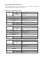
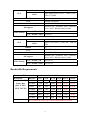
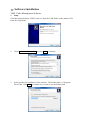
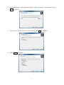
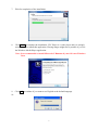
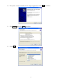
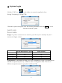
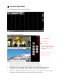
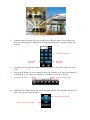
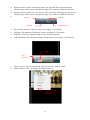
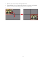
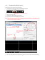
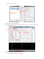
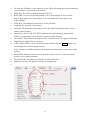
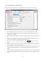
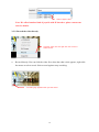
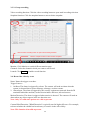
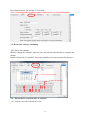
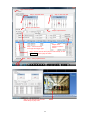
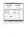
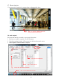
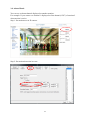
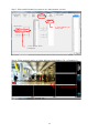
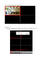
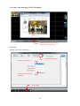
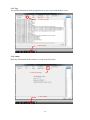
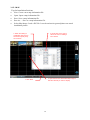
VMS Video Management Software Operation Manual FREE bundle Version 2.0-090723 1 Content Ⅰ. Software Installation--------------------------------------------------------5 Ⅱ. System Login ---------------------------------------------------------------12 Ⅲ. System Operation----------------------------------------------------------14 IV. Relay Viewer----------------------------------------------------------------34 2 System Hardware Requirements Before installing VMS software, make sure your system has the following recommended minimum hardware requirements. Minimum System Requirements CPU Level Atom Core Duel Refer Intel Atom 330 1.6G / Cache 512K / FSB 533 MHz 1G DRAM On Board / Intel 945GC VGA Network Interface Card OS Support Video Setting 1~9 Ch VGA / 20 FPS / 512K 1~12 Ch Level Intel Pentium Processor Refer Intel E5200 2.5G / Cache 2M / FSB 800 MHz 2G DRAM 128MB Video Ram VGA Network Interface Card OS Support 10/100 Ethernet Windows XP / Windows Vista / Windows Server 2003 / Windows Server 2008 VGA / 30 FPS / 1M 9~16 Ch VGA / 20 FPS / 512K 12~20 Ch CPU Level Intel Core 2 Dual Refer Intel E7200 2.53G / Cache 3M / FSB 1066 MHz DRAM VGA Network Interface Card OS Support Video Setting Windows XP / Windows Vista / Windows Server 2003 / Windows Server 2008 VGA / 30 FPS / 1M CPU Video Setting 10/100 Ethernet 2G 256MB Video Ram 10/100 Ethernet Windows XP / Windows Vista / Windows Server 2003 / Windows Server 2008 VGA / 30 FPS / 1M 16~24 Ch VGA / 20 FPS / 512K 20~32 Ch 3 CPU Level Intel Core 2 Quad Refer Intel Quad Q9550 2.83G / Cache 12M / FSB 1333 MHz 2G DRAM 256MB Video Ram VGA 10/100/1000 Ethernet Network Interface Card Windows XP / Windows Vista / Windows Server 2003 / Windows Server 2008 OS Support Video Setting VGA / 30 FPS / 1M 24~40 Ch VGA / 20 FPS / 512K 32~60 Ch CPU Level Intel Core I7 Refer Intel I7-920 2.66G / Cache 8M / FSB 4.8 GHz 3G DRAM 512MB Video Ram VGA 10/100/1000 Ethernet Network Interface Card Windows XP / Windows Vista / Windows Server 2003 / Windows Server 2008 OS Support Video Setting VGA / 30 FPS / 1M 40~128 Ch VGA / 20 FPS / 512K 60~128 Ch Bandwidth Requirements Bandwidth Table Bandwidth Statistics Resolution Bit Rate 1 Ch 4 Ch 16 Ch 32 Ch 64 Ch 128 Ch D1 / VGA / CIF Frame Rate (PAL 25 FPS / NTSC 30 FPS) 2 MPS 2M 8M 32 M 64 M 128 M 256 M 1.5 MPS 1.5 M 6M 24 M 48 M 96 M 192 M 1 MPS 1M 4M 16 M 32 M 64 M 128 M 768 KPS 768 K 3M 12 M 24 M 48 M 96 M 512 KPS 512 K 2M 8M 16 M 32 M 64 M 384 KPS 384 K 1.5 M 6M 12 M 24 M 48 M 256 KPS 256 K 1M 4M 8M 16 M 32 M We recommend using Giga switch in bandwidth of red data. 4 Ⅰ. Software Installation VMS: Video Management Software 1. Setup Click Recording Software VMS 2.0-std.exe from the VMS folder on the attached CD. Enter the setup mode. 2. Click I accept the agreement and select Next to continue. 3. Select a folder for installation of the software. The default path is C:\Program Files\VMS. Click Next to continue if you want to use the default path. 5 4. The default setting of the Start Menu folder is VMS. If you want to use this folder, click Next to continue. 5. If you want to create a shortcut on your desktop, click Next to continue. 6. Select Install to continue. 6 7. Wait for completion of the installation. 8. Click Finish to complete the installation. VSC Player is a video player and it is strongly recommended to install this application. Playing images might not be possible if you use the Windows Media Player application. Note: It is recommended to install Microsoft C Runtime if your OS is not Windows Vista. 9. Click OK to continue if you want to use English as the default language. 10. 7 10. The system is ready to install the VSC Player application. Click Next to continue. 11. Click I Agree and select Next to continue. 12. Click Next. 8 13. Select a path for installation of the application. The default path is C:\Program Files\VSC. Click Install to continue if you want to use this default path. 14. Wait for completion of the installation. 15. Click Finish to complete the installation. 9 Ⅱ. System Login Click the “VMS" icon on the desktop or execute the application from Start→ Programs→ VMS→ VMS. When the Login screen appears, enter the following information and click Login if you are first time to enter the system. Login ID: admin Password: admin Display: If you have connected to two monitors, you will see [Use 1 monitor] and [Use 2 monitors] in Display column. Each Monitor Max Layout Total Channels 1 monitor 64 64 2 monitors 64 128 3 monitors 36 108 4 monitors 36 144 Configuration: Configuration can help you to save all parameter of VMS. If you want to save different configuration, please key in different name in configuration field. You can save different configurations and to apply them in different VMS. 10 Ⅲ. System Operation: The VMS homepage appears when you log in. 3-1. Functions on main page Shut down VMS Minimize VMS Information When you click the full screen button, the objects and frames around the image disappear immediately. Sequence mode selection Information display Shut down VMS: You can close VMS and return to Windows. Minimize VMS: You can minimize VMS and return to Windows. Information: The information will be displayed below the video when click the information button, it display channel number, resolution, FPS and bit rate. Full screen: With the full-screen function activated, you can press the Esc key on your keyboard to deactivate this function and return to the main screen. 11 The full-screen function is activated. Sequence mode selection: You can switch to the sequence mode in a real-time way. You can select monitor 1 displayed in 9 Ch layout and monitor 2 displayed in 16 Ch layouts. Channel number input Page switch Next page Page switch Last page Virtual Keyboard: Input the channel number and enter, it will show you fast in white circle. Page switch: When you select sequence mode, for example: 4 Ch layout are channel 1 to channel 4, if you want to see channel 5 to channel 8, click the next page. Stop auto page switch Active auto page switch Sequence Tour: This function can active auto page switch. You can adjust the speed of page switch from 5 to 60 seconds. Remote camera control Remote camera zooms in/out 12 Remote camera control: You need to enter your login ID and password from the Channel page on the system configuration page if you want to enable this function. Remote camera zoom in/out: You need to enter your login ID and password from the Channel page on the system configuration page if you want to enable this function. Record Snapshot Playback Audio broadcast Record: The shortcut of Record, please see chapter 3-3 for details. Playback: The shortcut of Playback, please see chapter 3-6 for details. Snapshot: Click the snapshot button to start real-time snapshot. Audio Broadcast: The shortcut of Audio Upload, please see chapter 3-8 for details. HDD resource CPU resource CPU resources: You can monitor the CPU resources to avoid overload. HDD resources: You can monitor the HDD resources. Shortcut for ZOOM, Full Screen, Record, snapshot. 13 Shortcut: You can use shortcut with right click mouse. Drag-and-Drop: Click the Channel with left button of mouse and drag it to other location, the location will be changed when you set free the button. 14 3-2-1. Searching and Setting your cameras Search and set your cameras in local network. 1. Click the icon at right up corner to start IP Finder program. Step 1. Start IP Finder 2. Start to search IP CAM. 3. Click the IP CAM that has been searched. 4. Input the new name and IP address if necessary. Note: This program can search all IP CAM in local network. Please see next page if you want to connect to remote camera. Step 3. Clicking the IP CAM Step 4. Input the name and IP address if it is necessary. Step 2. Clicking search 5. Stay on the IP CAM and click right button of mouse to choose which CH and Streaming 15 protocol you want to set up. Step 5. Choosing CH and streaming protocol. Search and set your cameras in internet. Enter Configuration and click the channel setting page to input correct parameters to connect to your remote camera. Channel setting page. Input the parameter of remote camera. Configuration 3-2-2. Channel: Parameter settings for each camera Channel: Parameter settings for each camera 16 IP: Enter the IP address of the camera to be set. When all settings have been completed, click Connect for connection to the camera. RTSP Port: The TCP port with the default value 554. RTSP URL: If you are in the Mpeg4 mode, enter /cam1/mpeg4. If you are in the Motion Jpeg mode, enter /cam1/mjpeg. If you are in the sub stream mode, enter /cam1/mpeg4-2 . HTTP Port: The channel for the browser is 80 by default. Login ID: The login ID of the camera. Password: The password of the camera. Enter the login ID and password to execute remote camera control. Media Type: Select UDP, TCP, HTTP, multicast for video streaming transmission. HTTP is recommended if your network is protected with firewalls. Jitter Buffer: This function can help the video smoother, but it can’t apply to UDP type. Digital Zoom: Digital Zoom in and out. Audio Upload Codec: Choose the channel first and then click the talk button, you can transmit your sound to remote camera. Note: You have to install microphone in computer first and remote camera must install speaker. Media Batch Duration: Time for each clip of the video. (Unit: sec.) We recommend that the valve is 600(10 minutes). Media File Path: The path for storing the recorded video files. Snapshot File Path: The path for saving your snapshot file. 1. Select a camera to be set. 2. Camera parameter setting 17 3-3-1. Pre-Setting for recording the video Basic Recording Setting: Enter the configuration and click fundamental setting page. Click Fundamental for pre-setting of recording function. Viewer Matrix Layout: You can choose a layout to be your default viewer setting. Reserved Space: This function can avoid recordings use up the hard disk space. The default value is 100 MB. Media Storage Path: Assign the recording to a folder. There are 5 groups of path can be set. Overwrite the oldest archive if space is full: Active this function and then the system will overwrite the oldest space automatically if space is full. Recycle free space for each channel right now: Click execute button to recycle free space. Render video frame in full FPS: when CPU resources reach 100%, you can adjust the value from full to 1/5 to avoid system crash. Play key frames only to reduce CPU load: No matter you enable this function or not, it will be executed automatically to avoid system crash when CPU resources reach 100%. Joystick: When a joystick supported RS-485 connects to PC, you can set a proper value to active joystick control. These function support controls up, down, right, left, zoom in/out. 18 Select a proper value. Note: We afford another kind of joystick with IP interface; please contact our sales for details. 3-3-2. Record the video directly Click the video first and right click the mouse to select Record. Record directly: You can click the video first, when the white circle appears, right click the mouse to select record. Select record again to stop recording. A recording sign appears when you start record. 19 3-3-3. Group recording Video recording function: Click the video recording button to open multi recording selection. Snapshot function: Click the snapshot button to start real-time snapshot. Click record setting for group recording. Click the video recording button to open multi recording selection. Click the snapshot button to start real-time snapshot. Monitor: Click Monitor to switch different monitor page. Channels: Select the channels which you want to start record. Launch: Click Launch to enable record function. 3-4. Record the video by event Name: Name the trigger event here. Trigger Sources: 1. On Boot: The alarm is triggered by reboot. The camera will send an alarm when the system is rebooted due to power shortage, sabotage, or other reasons. 2. Alarm Input: The alarm is triggered by the security equipment connected from the DI terminals behind the machine, such as door/window detectors, infrared sensors. Motion Detection: The alarm is triggered when motion is detected. The camera will send an alarm when any objects appear in the set detection area. Note: Only N/A and start options are valid at present. Camera Blind Detection: "Blink Detection" is typically used in high traffic area. For example, to detect whether the exhibit has been destroy or remove in the office lobby. Note: This function is invalid at present. 20 Recording Duration: The default is 10 seconds. Note: event triggered recording requires remote devices to send notifications. 3-5. Record the video by scheduling Add: Add to the schedule. Modify: Change the schedule. Enter the time and date and click Modify to complete the change. Remove: Removal of a schedule. Select the schedule to be removed and click Remove. 1. Enter the date and time. 2. Add to the schedule. 3-6. Playback of a recorded video or snapshot 3-6-1. Search a recorded video from event. 21 Step 2. Event options. Step 5. Click end date. Step 3. Click start date. Step 4. Input start time. Step 6. Input end time. Step 8. Click Search to start the search. Step 7. Choose channel, event type and trigger type. Step 9. Double click the file to play the video directly or click Open Event button to play the video. Step 1. Video playback button. Step 10. The program will call VSC Media Player to play video. 22 3-6-2. Search a recorded video and snapshot from Media. Step 1. Media options. Step 3. Click end date. Step 2. Click start date. Step 4. Choose channel. Step 6. Click Search to start the search. Step 5. Choose video or snapshot. Step 7. Double click the file to play the video directly or click Play button to play the video. When you click Play, the program connects to the player automatically. It is recommended to use VSC Player. You can install this software following the setup of the main program. (Refer to Chapter 1.) 23 3-7. Rotate function You can use this function for cameras that are hung upside down. When you click the Rotate button, the image is presented upside down. 3-8. Audio upload This function can help you make a group audio broadcast. 1. You have to connect a speaker to your IP camera. 2. Check the setting of audio in IP camera, the audio mode must be active. 3. A microphone connected must be regular. Step 2. Name a group. Step 4. Move to enable list. Step 3. Select channel. Step 5. Click this button to speak on. Step 1. Audio upload shortcut button. 24 3-9. Alarm Watch You can see an alarm channel displayed on another monitor. For example: If you want to see channel 1 displayed on first channel (Ch37) of monitor 2 when motion is active. Step 1: Set motion area in IP camera. Step 2: Set motion detection in event. 25 Step 3: Select which channel you want to see when motion is active. 2. The channel you want to see. 1. The channel which is displayed. Step 4: When motion is active, a yellow indicated icon flashes. (Ch 1 of monitor 1) A yellow indicated icon flash. 26 Step 5: A video displays on Ch37 of monitor 2. A video is displayed. 3-10. Lock You can use this function to lock all functions of the product to avoid unauthorized access. The password for this function is admin. 2. Enter the password and click Unlock to quit the screen saver mode. 1. When you click the screen saver button, the following popup window appears and you are entering the screen saver mode. 27 3-11. Link to the main page of IP CAM quickly. Click this button to connect to the webcam page automatically. 3-12. User Settings for access permission 2. click user setting page. 3. Select an access level. 4. Change and confirm the password. 1. Click Config. 28 3-13. Log Record the information about program boot up, user log in and channel event. 2. Click Log page. 1. Click Config. 3-14. About Show the information about software version and release date. 2. Click About page. 1. Click Config. 29 3-15. eMAP Tips for Installation Positions New: Create a new map information file. Open: Open a map information file. Save: Save a map information file. Save As…: Save as a map information file. Select Map Image: Load a JPG file. It can be an interior ground plan or an actual installation picture. 3. Right-click on the map to call uo the icon for adding a new camera. 4. When the setting is completed, click Save to save this map file (JPG) as xxx.ini file. 2. Open the file and click Select Map Image to load the JPG file you want to display. 1. Click MAP. 30 IV. VMS 2.0 Relay Viewer This function allows you to monitor the video remotely. The max monitoring IP cameras are 16 channels. 1. Connect to VMS 2.0 Relay viewer; just input the IP address of PC that installs the VMS. Input the IP address of PC installed VMS Input ID and password to log in. 2. Input ID and Password to log in. Note: ID and Password are the same as VMS. 3. Select the video lay out first and double click the camera channel, a video will be displayed. Note: The same effect if you use camera connect or camera disconnect. 2. Double click the camera channel. 3. A video is displayed. 1. Select which location you want to see first. 31 4. VMS Connect / Disconnect: You can connect to other VMS if you have several VMS needed to be monitor. 5. Up / Down / Left / Right / Home: Control the directions of IP camera. 6. Zoom In / Out: Control the zoom of IP camera. 7. Focus Near / Far: Control the focus of IP camera. 8. Configure: Set the path of record and snapshot. Set path of record and snapshot. 9. Sequence mode selection: You can switch to the sequence mode in a real-time way. There are 4 kind of sequence can be selected; 1, 4, 9 and 16 layout. Select sequence mode. 32