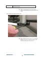
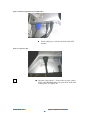
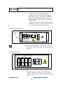
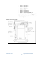
1
Agilent Technologies Medalist x6000 System Installation and Verification Medalist x6000 Installation and System Verification Legal Notices, Warranty and Safety 1 Legal Notices .......................................................................................................................................... i Copyrights ................................................................................................................................................... i Trademarks.................................................................................................................................................. i Technology Licenses Notice ........................................................................................................................ i U.S. Government Restricted Rights ............................................................................................................. i Agilent Address........................................................................................................................................... ii 2 Warranty.............................................................................................................................................. iii 3 Safety Summary................................................................................................................................... iv General.......................................................................................................................................................iv Before Applying Power...............................................................................................................................iv Ground the Equipment ................................................................................................................................v Fuses............................................................................................................................................................v Do Not Operate in an Explosive Atmosphere..............................................................................................v Do Not Remove Equipment Cover...............................................................................................................v Do Not Operate Damaged Equipment........................................................................................................vi Do Not Service or Adjust Alone..................................................................................................................vi Do Not Substitute Parts or Modify Equipment ...........................................................................................vi Maintain the System as Recommended.......................................................................................................vi Follow All X-ray Safety Requirements and Legislation..............................................................................vi 4 Safety Symbols and Notices .............................................................................................................. viii Warning ................................................................................................................................................... viii Caution .................................................................................................................................................... viii Note ......................................................................................................................................................... viii Safety and Electric Symbols .................................................................................................................... viii 5 Emergency Stop .....................................................................................................................................x 6 De-energizing the X-ray Tube ........................................................................................................... xii Methods for de-energizing the X-ray tube:............................................................................................... xii X-Ray Control Off Button and X-Ray Control Key on the Operator Control Panel............................. xii PDU Enable Switch and Lockable Breaker ......................................................................................... xiii AC “Mains” Power Disconnect ........................................................................................................... xiv 7 X-Ray Safety ........................................................................................................................................xv Effects of Radiation ..................................................................................................................................xvi X-ray Dose Limits.....................................................................................................................................xvi Definition of a Cabinet X-ray System .......................................................................................................xvi Built-In Safety Features...........................................................................................................................xvii Registration Requirements ......................................................................................................................xvii 8 High Voltage Safety......................................................................................................................... xviii High Voltage Subsystem .........................................................................................................................xviii Power Distribution Unit (PDU) ........................................................................................................... xix 9 Mechanical Safety................................................................................................................................xx 10 Service and Support .......................................................................................................................... xxi Agilent Technologies Service Center........................................................................................................xxi System Installation and Verification 1 Overview ............................................................................................................................................... 1 2 Preparing for Agilent Medalist x6000 Installation ............................................................................ 2 3 Time Required for Installation............................................................................................................ 3 4 What has to be done before installation begins?................................................................................ 4 5 System Arrival, Inspection and Placement......................................................................................... 5 6 System Hardware Installation and Setup ......................................................................................... 13 7 System Performance Verification Procedure ................................................................................... 23 8 System Start-up................................................................................................................................... 27 9 Panel Handling Subsystem Verification ........................................................................................... 31 10 MSD Suggestion for Improvement Form ......................................................................................... 37 11 SMEMA – Appendix A ...................................................................................................................... 38 Introduction .............................................................................................................................................. 38 SMEMA Signals........................................................................................................................................ 38 SMEMA Connectors ................................................................................................................................. 40 12 Wiring Configuration – Appendix B................................................................................................. 42 Wiring Configuration ............................................................................................................................... 42 3-Phase Wye or Delta............................................................................................................................... 44 3-Phase Wye with Neutral ........................................................................................................................ 45 Legal Notices, Warranty and Safety 1 Legal Notices .......................................................................................................................................... i Copyrights ................................................................................................................................................... i Trademarks.................................................................................................................................................. i Technology Licenses Notice ........................................................................................................................ i U.S. Government Restricted Rights ............................................................................................................. i Agilent Address........................................................................................................................................... ii 2 Warranty.............................................................................................................................................. iii 3 Safety Summary................................................................................................................................... iv General.......................................................................................................................................................iv Before Applying Power...............................................................................................................................iv Ground the Equipment ................................................................................................................................v Fuses............................................................................................................................................................v Do Not Operate in an Explosive Atmosphere..............................................................................................v Do Not Remove Equipment Cover...............................................................................................................v Do Not Operate Damaged Equipment........................................................................................................vi Do Not Service or Adjust Alone..................................................................................................................vi Do Not Substitute Parts or Modify Equipment ...........................................................................................vi Maintain the System as Recommended.......................................................................................................vi Follow All X-ray Safety Requirements and Legislation..............................................................................vi 4 Safety Symbols and Notices .............................................................................................................. viii Warning ................................................................................................................................................... viii Caution .................................................................................................................................................... viii Note ......................................................................................................................................................... viii Safety and Electric Symbols .................................................................................................................... viii 5 Emergency Stop .....................................................................................................................................x 6 De-energizing the X-ray Tube ........................................................................................................... xii Methods for de-energizing the X-ray tube:................................................................................................xii X-Ray Control Off Button and X-Ray Control Key on the Operator Control Panel............................. xii PDU Enable Switch and Lockable Breaker ......................................................................................... xiii AC “Mains” Power Disconnect ........................................................................................................... xiv 7 X-Ray Safety ........................................................................................................................................xv Effects of Radiation ..................................................................................................................................xvi X-ray Dose Limits.....................................................................................................................................xvi Definition of a Cabinet X-ray System .......................................................................................................xvi Built-In Safety Features...........................................................................................................................xvii Registration Requirements ......................................................................................................................xvii 8 High Voltage Safety......................................................................................................................... xviii High Voltage Subsystem .........................................................................................................................xviii Power Distribution Unit (PDU) ........................................................................................................... xix 9 10 Mechanical Safety................................................................................................................................xx Service and Support .................................................................................................................... xxi Agilent Technologies Service Center .................................................................................................. xxi 1 Legal Notices Copyrights © Agilent Technologies, Inc. 2007 Trademarks Agilent® is a registered trademark of Agilent Technologies, Inc. Intel® is a U.S. registered trademark of Intel Corporation. Java™ is a U.S. trademark of Sun Microsystems, Inc. Adobe®, the Adobe Logo, Acrobat® and the Acrobat Logo are trademarks of Adobe Systems Incorporated. Microsoft®, Windows XP®, and MS-DOS® are U.S. registered trademarks of Microsoft Corp. Technology Licenses Notice The hardware and/or software described in this document are furnished under a license and may be used or copied only in accordance with the terms of such license. U.S. Government Restricted Rights Rights If software is for use in the performance of a U.S. Government prime contract or subcontract, Software is delivered and licensed as "Commercial computer software" as defined in DFAR 252.227-7014 (June 1995), or as a "commercial item" as defined in FAR 2.101(a) or as "Restricted computer software" as defined in FAR 52.227-19 (June 1987) or any equivalent agency regulation or contract clause. Use, duplication or disclosure of Software is subject to Agilent Technologies’ standard commercial license terms, and non-DOD Departments and Agencies of the U.S. Government will receive no greater than Restricted Rights as defined in FAR 52.227-19(c)(1-2) (June 1987). U.S. Government users will receive no greater than Limited Rights as defined in FAR 52.227-14 (June 1987) or DFAR 252.227-7015 (b)(2) (November 1995), as applicable in any technical data. Rev. A Legal Notices, Warranty and Safety i Agilent Address Agilent Technologies Measurement Systems Division 900 S. Taft Avenue Loveland, CO 80537-6378 Rev. A Legal Notices, Warranty and Safety ii 2 Warranty The material contained in this document is provided "as is," and is subject to being changed, without notice, in future editions. Further, to the maximum extent permitted by applicable law, Agilent disclaims all warranties, either express or implied with regard to this manual and any information contained herein, including but not limited to the implied warranties of merchantability and fitness for a particular purpose. Agilent shall not be liable for errors or for incidental or consequential damages in connection with the furnishing, use, or performance of this document or any information contained herein. Should Agilent and the user have a separate written agreement with warranty terms covering the material in this document that conflict with these terms, the warranty terms in the separate agreement will control. Rev. A Legal Notices, Warranty and Safety iii 3 Safety Summary Summary WARNING There are many warnings and cautions outlined in the next sections. Properly follow ALL Warnings and Cautions. General The following general safety precautions must be observed during all phases of operation, service and repair of this product. Failure to comply with these precautions or with specific warnings elsewhere in this manual violates safety standards of design, manufacture, and intended use of the product. Agilent Technologies, Inc. assumes no liability for the customer's failure to comply with these requirements Prior to operating or performing maintenance activities on the Medalist x6000, personnel should be aware of system safety precautions. The Medalist x6000 is designed to be safe, provided proper use and service precautions are observed. All users should be aware of the following areas of safety: Emergency Stop — How to shut off the Medalist x6000 Main Cabinet in an emergency situation. De-energizing the X-ray Tube X-Ray Safety — Effects of Radiation and the safeguards against exposure. High Voltage Safety – High Voltage and safe servicing practices. Mechanical Safety — Mechanical motion and safety precautions. Before Applying Power Power Verify that the product is set to match the available line voltage, the correct fuses or main circuit breaker is installed, and all safety precautions are taken. Note the instrument's external markings described under Safety Symbols and Notices. Rev. A Legal Notices, Warranty and Safety iv Ground the Equipment To minimize shock hazard, the instrument chassis and cover must be connected to an electrical protective earth ground. The instrument must be connected to the ac power mains through a grounded power cable, with the ground wire firmly connected to an electrical ground (safety ground) at the power outlet. Any interruption of the protective (grounding) conductor or disconnection of the protective earth terminal will cause a potential shock hazard that could result in personal injury. This is a Safety Class 1 instrument (provided with a protective earth terminal). An uninterruptible safety earth ground must be provided from the main power source to the product input wiring terminal or supplied power cable. The protective features of this product may be impaired if it is used in a manner not specified in the operation instructions. Fuses For continued protection against fire, only the fuses with the required rated current, voltage, and specified type (normal blow, time delay, etc.) should be used. Go to the Service section of the on-line help for the specifications for each fuse. Do not use repaired fuses or short-circuited fuse holders. To do so could cause a shock or fire hazard. Do Not Operate in an Explosive Atmosphere Atmosphere Do not operate the instrument in an explosive atmosphere or the presence of flammable gases or fumes. Do Not Remove Equipment Cover Cover Operating personnel must not remove instrument covers or shields. Component replacement and internal adjustments must be made only by service-trained personnel. Under certain conditions, dangerous voltages may exist even with the equipment switched off. To avoid dangerous electrical shock, DO NOT perform procedures involving cover or shield removal unless you are qualified to do so. Do Not Operate Damaged Equipment Whenever it is possible that the safety protection features built into this product have been impaired, either through physical damage, excessive moisture, or any other reason, REMOVE POWER and do not use the product until safe operation can be verified by service-trained personnel. If necessary, contact your Agilent Technologies Service Center for service and repair to ensure that safety features are maintained. Rev. A Legal Notices, Warranty and Safety v Equipment that appears damaged or defective should be made inoperative and secured against unintended operation until they can be repaired by qualified service personnel. See the Lock Out /Tag Out procedure in the Service section of the on-line help. Do Not Service or Adjust Alone Alone Do not attempt internal service or adjustment of this instrument unless another person, capable of rendering first aid and resuscitation, is present. Do Not Subst Substitute Parts or Modify Equipment Equipment Because of the danger of introducing additional hazards, do not install substitute parts or perform any unauthorized modification to the product. Contact your Agilent Authorized Service Representative for service and repair to ensure that safety features are maintained. Maintain the System as Recommended The recommended preventive maintenance for the system is documented in the on-line help. Preventive maintenance should always include testing the emergency shut down (EMO) switch by pressing it and verifying that all ac and dc power turns off. Foll Follow All XX-ray Safety Requirements and Legislation DO NOT operate the equipment unless an X-ray safety survey has been performed within the last six (6) months, when the Medalist x6000 is installed at a site, when the Medalist x6000 has been moved, and immediately following maintenance that involves the safety interlock subsystem, the lead shielding or the X-ray source. Do not operate this equipment without complying to these recommendations. Owners/Operators of this equipment are responsible for compliance with all local legislation regarding X-ray equipment. An Operator’s Guide and Declaration of Conformity in a local language is available upon request to Agilent Technologies, Inc. Rev. A Legal Notices, Warranty and Safety vi 4 Safety Symbols and Notices Warning WARNING The WARNING symbol denotes a hazard. It calls attention to a procedure, practice, or condition, which, if not correctly performed or adhered to, could result in personal injury or death. Do not proceed beyond a WARNING symbol until the indicated conditions are fully understood and met. Caution CAUTION The CAUTION symbol denotes a hazard. It calls attention to an operating procedure, or condition, which, if not correctly performed or adhered to, could result in damage to or destruction of part or all of the product or permanent loss of data. Do not proceed beyond a CAUTION symbol until the indicated conditions are fully understood and met. Note NOTE The NOTE symbol contains important information. Safety and Electric Symbols These symbols are used on labels on the product and in the documentation. They indicate that the user must refer to the manual for specific information to avoid personal injury or damage to the product. Symbol Description Warning, hazardous voltage (electrical hazard). Warning, this equipment produces X-rays when energized. Caution, refer to accompanying documents for specific WARNING or CAUTION information to avoid bodily injury or damage to the equipment. (Canada) Warning, this equipment produces X-rays when energized. Warning, pinch hazard. Keep hands away to avoid injury. Rev. A Legal Notices, Warranty and Safety vii Warning, pinch hazard. Keep hands away to avoid injury. Warning, clamp pinch hazard. Keep hands away to avoid injury. Indicates the field wiring terminal that must be connected to earth ground before operating the equipment -- protects against electrical shock in case of fault. Direct current (dc). Frame or chassis ground terminal — typically connects to the equipment’s metal frame. Alternating current (ac) Rev. A Legal Notices, Warranty and Safety viii 5 Emergen Emergency Stop CAUTION The emergency stop buttons are intended for use in emergency situations only and should not be used for normal system shut down. Repeated misuse of the emergency stop buttons will eventually cause damage to certain components or the loss of data or both. Figure 1 Emergency Stop Push down on one of the emergency stop buttons in an emergency situation. The emergency stop button locks OFF when pushed. The emergency stop is used to quickly shut down power to the Medalist x6000. The emergency stop is intended for crisis situations only and should not be used as the normal means to stop the Medalist x6000. Rev. A Legal Notices, Warranty and Safety ix The Medalist x6000 is equipped with two emergency stop buttons. The emergency stop buttons are located on either side of the Medalist x6000, centered above the outer barrier panels. Whenever one of the emergency stop buttons is pressed, all power is immediately removed from the Medalist x6000 subsystems, with the exception of the system controller and the monitor. To restart the Medalist x6000 after the emergency stop button has been pushed (provided the condition which caused the operator to engage the emergency stop button has been cleared) requires the emergency stop release key and the normal Medalist x6000 startup procedure. Rev. A Legal Notices, Warranty and Safety x 6 DeDe-energizing the XX-ray Tube In case of a disaster such as fire, explosion, flood, or strong earthquake, the X-ray tube must be de-energized immediately. In an emergency, de-energize the X-ray tube by one of the following methods: NOTE An electrical brownout or electrical power off, due to storms, does not constitute an emergency since the system will simply shut itself off and may be restarted in the normal manner after the power returns. Methods for dede-energizing the XX-ray tube: Any one of the following actions will de-energize the X-ray tube: Press one of the emergency stop buttons. Press the X-ray Control off (0) button on the operator control panel Turn the X-ray Control key to the off (0) position on the operator control panel. Turn the PDU enable switch to the off position. Move the lockable switch on the PDU to the “O” or off position. Open the AC “mains” disconnect circuit breaker supplying power to the Medalist x6000. Once de-energized, the X-ray tube emits no radiation. After a disaster that may have resulted in damage to the Medalist x6000 shielding, an X-ray safety test of the Medalist x6000 must be performed prior to placing it back in operation. Consult the Agilent Technologies Service Center before attempting to return the Medalist x6000 to operation. X-Ray Control Off Button and XX-Ray Control Key on the Operator Operator Control Panel To de-energize the X-ray tube using the operator control panel: Press the X-ray Control off (0) button on the operator control panel Turn the X-ray Control key to the off (0) position on the operator control panel. Rev. A Legal Notices, Warranty and Safety xi Figure 2 X-ray Control Off Button and X-Ray Control Key on the Operator Control Panel X-ray Control Off Button X-ray Control Key in the Off Position PDU Enable Switch and Lockable Breaker To de-energize the X-ray tube using the PDU enable switch and lockable breaker: Turn the PDU enable switch to the off position. Move the lockable switch on the PDU to the O or off position. Rev. A Legal Notices, Warranty and Safety xii Figure 3 PDU Enable Switch and Lockable Breaker ! Power Distribution Unit 0 1 1 0 Main disable can be locked in the “0” position. AC “Mains” Power Power Disconnect The AC “mains” power disconnect is a circuit breaker typically installed by the end user and should be located within 15 feet of the Medalist x6000 power distribution unit (PDU). Local codes and needs will define the accessibility, configuration, and size of this disconnect. This disconnect will disconnect all power to the Medalist x6000. Rev. A Legal Notices, Warranty and Safety xiii 7 X-Ray Safety WARNING This product produces XX-rays. Do not attempt to open or modify any part of the product. Do not operate this product or turn on the XX-ray source unless all shielding is in place. Operation without shielding shielding in place can result in exposure to XX-rays which can cause serious bodily injury or death. Refer all servicing to serviceservice-trained personnel. WARNING Do not, for ANY reason, attempt to defeat the builtbuilt-in safety interlocks. Operation Operation without the Safety Interlock Subsystem functional can result in exposure to XX-rays, rays, high voltage, voltage, or moving components. components. Exposure to XX-rays and moving components can cause serious bodily injury or death. death. Contact with high voltage can cause electrical shock shock resulting resulting in serious bodily injury or death. Refer all servicing to serviceservice-trained personnel. WARNING Consult the Agilent Technologies Service Center before attempting to service any components of the XX-ray Subsystem. WARNING Agilent recommends an xx-ray safety test be performed under the following conditions: every six (6) months, • when the Medalist x6000 is installed at a site, • when the Medalist x6000 has been moved, • immediately following following maintenance that involves the Safety Interlock Subsystem, the lead shielding, the XX-ray tube, or the HVPS. Do not operate this equipment without complying to these recommendations. WARNING Verify that the XX-ray tube has an external external green ground wire going directly to the ground connection on the XX-ray high voltage power supply. This safety ground is in addition to the ground supplied by the high voltage cable and the XX-ray tube Mount. WARNING Do not drill or modify the shielding panels in ANY way. WARNING If XX-ray shielding is removed from the product or disturbed for any reason, the product must not be operated until the shielding is reinstalled and an XX-ray safety test (survey) is performed performed by trained personnel CAUTION Do not place any strong magnets near the XX-ray tube. tube. Any magnets stronger than 50 gauss placed immediately at the position of the deflection coils could cause the electron beam to hit the side of the the XX-ray tube. The entire XX-ray tube tube is shielded in the Medalist x6000 System, so, no additional radiation will be emitted from the system. However, proper operation of the machine may not be possible in a strong magnetic field. CAUTION Do not apply pressure to, modify or damage the XX-ray vacuum window. The XX-ray vacuum window supports the tungsten target material. If the XX-ray vacuum window is broken, the XX-ray tube will cease to operate. Rev. A Legal Notices, Warranty and Safety xiv xiv Effects of Radiation There are a variety of natural and man-made emissions that are classified as radiation. X-rays are included in most definitions. It should be noted that the Medalist x6000 will not produce X-rays unless power is specifically provided to the X-ray tube, and will cease immediately upon removal of power. It should also be noted that the Medalist x6000 is not designed to admit humans. A complete description of the biological effects of radiation is outside the scope of this guide, but is generally available at any library or local government office. X-ray Dose Limits The State of California (see California Radiation Control Regulations, Title 17, California Administrative Code, Section 30265), and other Agreement States, have established maximum dose limits for individuals working in an area considered to be uncontrolled (not under constant monitoring). These limits are the maximum of no more than: 2 millirem / hour 100 millirem / 7 days 500 millirem / year These limits were considered when the United States federal government established the limit of 0.5 milliroentgen/hour at 5 cm from the surface of any Cabinet Radiography system. Agilent certifies that the Medalist x6000 X-ray emissions are less than the United States Government and International Safety Standards for Cabinet X-ray Systems. Definition of a Cabinet XX-ray System A Cabinet X-ray System is one that produces little or no Xray exposure to the user and is safe to operate and to be in close proximity to under foreseeable conditions. The Medalist x6000 is certified to produce not more than 0.5 millirem per hour at a distance of 5 cm from the machine surface. Agilent warrants that the Medalist x6000 meets all federal regulations regarding Cabinet Radiography Systems. Rev. A Legal Notices, Warranty and Safety xv The Medalist x6000 is classified as a “Cabinet X-Ray System” by the United States Code of Federal Regulations: 21 CFR 1020.40 (X-Ray). The Medalist x6000 is designed, manufactured and registered in accordance with strict criteria established by the Department of Health and Human Services, Food and Drug Administration, Center for Devices and Radiological Health (CDRH), Department of Health and Human Services (DHHS), X-ray Products Branch. Agilent certifies that the Medalist x6000 X-ray emissions are less than United States Government and International Safety Standards for a “Cabinet X-ray Systems.” BuiltBuilt-In Safety Features The Medalist x6000 is enclosed in shielding that limits Xray exposure to normal background levels and all of the Medalist x6000 access ports are safety interlocked to prevent any accidental radiation exposure. In addition, Agilent performs an X-ray safety test two times on every system prior to customer use: During manufacturing. At the user’s facility. Agilent further warrants and certifies that the Medalist x6000 fully passes the approved Certification Test for compliance with 21 CFR 1020.40 after shipping and installation at the customer's facility. Several Medalist x6000s are currently in operation throughout the world. These systems meet local and government X-ray exposure standards. Registration Registration Requirements Customers are directed to check with their state radiation control program director for registration requirements. Rev. A Legal Notices, Warranty and Safety xvi 8 High Volta Voltage Safety WARNING open en any part of the product. This product produces high voltage potentials. Do not attempt to op Contact with high voltage can cause electrical shock resulting in serious bodily injury or death. Refer all servicing to serviceservice-trained personnel. WARNING Always DISCHARGE all high voltage connections prior prior to servicing. WARNING Do not operate the XX-ray high voltage power supply without the high voltage Cable connecting it to the XX-ray tube properly installed. The high voltage connections are not user serviceable. Refer service to service servicevice-trained personnel only. WARNING Do not disconnect any motor cables from the motor or servo module unless you are certain the motor is not spinning. A spinning motor can generate hazardous voltages. CAUTION Do not kink or sharply bend the high voltage cable, as it is used to supply a ground and the high voltage to the XX-ray tube. tube. Sharp bending tends to lower the dielectric strength of the high voltage cable and may lead to failure of the system. Since one ground ground is provided through the shielding of the high voltage cable, the cable should be kept free of cracks in the insulation, kinks or punctures. High Voltage Subsystem NOTE For support purposes, the following components make up the high voltage subsystem: X-ray tube assembly, X-ray high voltage power supply and the high voltage power supply cable. NOTE The Medalist x6000 has no exposed high voltage potentials. High voltages are contained within subsystems, and should only be accessed by Agilent personnel. The high voltage subsystem’s high voltages are contained within the x-ray high voltage power supply, the high voltage power supply cable, and the X-ray tube assembly. Under no conditions are the high voltage subsystems user serviceable. The X-ray high voltage power supply produces up to 160,000 volts direct current (dc). Should any damage occur to any of the high voltage components, remove power from the system, and contact the Agilent Response Center prior to attempting any further operation of the Medalist x6000. Rev. A Legal Notices, Warranty and Safety xvii Power Distribution Unit (PDU) The Medalist x6000 is powered by 200-240VAC Wye or Delta or 220/380-240/415 VAC wye with neutral, 3-phase, 50/60Hz (cycles) AC mains. The PDU provides an output of 200-240VAC 50/60Hz to the Medalist x6000 subsystems. The PDU can be reconfigured based on the AC mains input to provide the appropriate AC voltage to the Medalist x6000 subsystems. The PDU outputs are protected with either a 10A 250VAC fuse or a 15A 250VAC thermal circuit breaker. The PDU provides emergency stop control via a 12Vdc control circuit. The PDU will disconnect power to all switched subsystems via an internal contactor by: Pressing one of the emergency stop push buttons Opening the AC mains disconnect circuit breaker supplying power to the Medalist x6000. The emergency stop circuit will not power off the system controllers or monitor. Rev. A Legal Notices, Warranty and Safety xviii 9 Mechanical Safety WARNING Motion mechanics within the Medalist x6000 involve highhigh-speed, speed, mechanical subassemblies. Lock--Out /TagImproper handling or inattention could cause serious bodily injury. Perform a Lock /Tag-Out prior to servicing. WARNING This product contains high speed motion components. The motion components can cause severe bodily injury. Do not attempt to open any part of this product while the motion components are operational. Do not attempt to defeat the safety interlocks. WARNING Do not insert any portion of the body into the XY stage assembly or the outer barrier, barrier, as these contain moving mechanisms and harm may come to the user, even though movable barriers are present. The motion mechanics of the Medalist x6000 involve high speed mechanical assemblies, including the panel conveyors and the XY stage assembly. Mishandling could result in bodily injury. To help prevent any risk of injury, the major motion components of the Medalist x6000 are enabled through the safety interlock subsystem. If an access panel is open, or if an incorrect sensor state is sensed, the X-axis, Yaxis, and X-ray subsystem functions are ceased. Rev. A Legal Notices, Warranty and Safety xix 10 Service and Support Agilent Technologies Service Center Any adjustment, maintenance, or repair of this product must be performed by qualified personnel. Contact your Agilent Authorized Service Representative through your local Agilent Technologies Service Center. Table 1: Support and Service Contacts Location Contact Worldwide http://www.agilent.com/find/support, select the Technical Support link United States & Canada Customer Support Center (800) 447-8378 All Other Countries/Regions Specific local information is available through this same web site location. Select the desired country or region and the phone numbers and electronic mail addresses will display. NOTE The telephone numbers and URLs provided are liable to change. Please check with your Support or Marketing group for the latest information. Rev. A Legal Notices, Warranty and Safety xx System Installation and Verification 1 Overview ............................................................................................................................................... 1 2 Preparing for Agilent Medalist x6000 Installation ............................................................................ 2 3 Time Required for Installation............................................................................................................ 3 4 What has to be done before installation begins?................................................................................ 4 5 System Arrival, Inspection and Placement......................................................................................... 5 6 System Hardware Installation and Setup ......................................................................................... 13 7 System Performance Verification Procedure ................................................................................... 23 8 System Start-up................................................................................................................................... 27 9 Panel Handling Subsystem Verification ........................................................................................... 31 10 MSD Suggestion for Improvement Form ..................................................................................... 37 11 SMEMA – Appendix A .................................................................................................................. 38 Introduction .............................................................................................................................................. 38 SMEMA Signals........................................................................................................................................ 38 SMEMA Connectors ................................................................................................................................. 40 12 Wiring Configuration – Appendix B............................................................................................. 42 Wiring Configuration ............................................................................................................................... 42 3-Phase Wye or Delta............................................................................................................................... 44 3-Phase Wye with Neutral ........................................................................................................................ 45 1 Overview This document guides you through the Agilent Medalist x6000 installation process. In the printed version, all major steps have check boxes like the one to the side of this paragraph, on the left side of the page. Use these check boxes as you proceed with the installation to ensure all steps of the installation are complete. NOTE Installation is intended to be performed by an Agilent authorized service representative only. N7280N7280-9003490034- Rev. A System Installation and Verification 1 2 Preparing for Agilent Medalist x6000 Installation You will need to refer to the following documents. Unpacking Instructions (N7280-90010) Site Preparation Manual (N7280-90009) Agilent Medalist x6000 Help Agilent Electrostatic Discharge Control Specification (A5951-1589-1) You will need a copy of the x6000 X-ray Safety Test Procedure (N7280-90093) and the x6000 X-Ray Safety Test Report (N7280-90076) to complete the installation. You need to acquire these before entering the customer site. These documents are available at http://www.agilent.com/find/x6000. Click Technical Support and then click Download X-Ray Safety Test Procedure. The unpacking instructions (N7280-90010) will be located on the outside of the crate. The Site Preparation Manual has been sent to the customer before this installation began. The Agilent Medalist x6000 help is on-line when you get the system up and running. The ESD document is one of general corporate nature that you should be familiar with already. If you are not, please review it as soon as possible. N7280N7280-9003490034- Rev. A System Installation and Verification 2 3 Time Required for Installation It will generally take 8 hours to install the Agilent Medalist x6000 System. If this is the first installation at the site, the Medalist x6000 Operator Training should also be provided for the customer’s primary operators. NOTE Maintenance Training is required for Cooperative Support customers in Europe. The time estimate is a general guideline. You may take more or less time to install the Medalist x6000 system depending on the customer’s requirements, what components are to be installed, and how the Medalist x6000 system is handled throughout the delivery and installation process. N7280N7280-9003490034- Rev. A System Installation and Verification 3 4 What has to be done before installation begins? All system components and software have been delivered and an acceptable site has been chosen for installation. All utilities (air, electric, etc.) are ready for the installation and are at the site of installation as specified in the Site Preparation Manual. NOTE An Agilent authorized service representative must be present to break the seal on the truck and for pallet unloading, system movement, uncrating and placement (whenever possible). Table 1: Required tools and equipment (In addition to your standard tool kit you will need the following tools): Description Notes Tower Door T- handle 5/16 inch (8710-2341) GM (Geiger Mueller) Radiation meter Victoreen/Inovision/Fluke 190, 290 GM Technical Associates P-8 Neon GM Berthold TOL-F GM/Ion Chamber (Europe Europe Only) Only Ion Chamber Radiation meter • Inner and Outer Barrier Interlock Tool Kit N7280-88784 Panel Handling Test Panel N7280-60151 Interlock Adjustment Meter Kit N7280-88783 Victoreen/Inovision/Fluke 440 RF/D, 451P, 450P Ion Chamber N7280N7280-9003490034- Rev. A System Installation and Verification 4 5 System Arrival, Inspection and Placement An acceptable site must be prepared prior to the installation of the Medalist x6000 System. This includes: Having a level floor capable of supporting 3220 kg (~7100 pounds) 371 kilograms per square meter (76 pounds per square foot) 805 kilograms on 152mm diameter pad, on four pads 131 x110 centimeter centers (1775 lbs. on 6 inch diameter pads on 52 x 43 inch centers) Clearances for all equipment, power and air utilities and acceptable climate control. Movement to the final location should be considered before transportation. Make sure there is a travel route with sufficient access clearances throughout the course of movement (this includes the turning radius for the Medalist x6000 and the forklift). Figure 1: Medalist x6000 ready for crating This photo shows a x6000 as it is waiting to be shipped from the manufacturing facility. This is how it will look just prior to crating. For shipment, it will have a complete crate around it. N7280N7280-9003490034- Rev. A System Installation and Verification 5 The main unit will be on a pallet 188 centimeters wide by 229 centimeters long (74 x 90 inches). This pallet requires a forklift with a rated lifting capacity of at least 4536 kilograms (10,000 pounds). The tines on the forklift must be at least 152 centimeters (60 inches) long, each tine must be no more than 19 centimeters (7.50 inches) wide. The main unit, crated and on its pallet, will be approximately 244 centimeters (96 inches) high. Consider this height, plus the lift height when moving the Medalist x6000. NOTE To prevent rusting any x6000 Systems that are delivered to a high humid / high temp environment should not have the vapor barrier removed until the x6000 has reached equilibrium with the inside temperature of the factory floor. Figure 2: Moving the system Fork lift tines should be set to 85 cm (33.5 inch) centers and be 152 cm (60 inches) long (minimum) Opening for tines is 19 cm (7.5 in.) wide Use fork lift here only. Front of System CAUTION Lift the system where shown only. Do Not use a lift or jack on the rest of the frame or system damage could occur. N7280N7280-9003490034- Rev. A System Installation and Verification 6 1 Check for Gross Damage — Look for and record any damage to packing materials, etc. Note any areas where the equipment has been exposed. Document any damage on the waybill. Advise the carrier and contact the Agilent Customer Support Center or an Agilent authorized service representative immediately. If significant damage exists, document the damage completely (take pictures if possible) prior to further unpacking or movement. 2 Accessories — If there is an accessories box, it is advisable to move it to the installation area before opening. 3 Verify Items Shipped — An Agilent authorized service representative must be present for system and crate unloading, system movement, and system placement: (whenever possible) Inspect all received containers and verify the correct number of items arrived with the shipment. (See the packing list. If the packing list is missing, contact the customer facility receiving personnel.) Figure 3: System dimensions Height (Max.) 242 cm (95 in.) Depth 193 cm (76 in.) Width 152 cm (60 in.) N7280N7280-9003490034- Rev. A System Installation and Verification 7 NOTE The system while on its pallet is 2.44 meters or 96 inches high. This height plus the required forklift lifting distance is needed for (clearance) movement while on the shipping pallet. 4 CAUTION CAUTION WARNING Move Medalist x6000 To Install Site — When you are ready, (using acceptable lifting equipment) raise the Medalist x6000 from its pallet and move to the install area. Be very careful while moving the forklift in place to remove the Medalist x6000 from its pallet. You should do this from the front of the unit and ensure forks protrude entirely through the frame (you can see them on the other side) to enable secure movement of the system. 5 Staging — Organize all materials in the installation area. Prior to beginning installation, find the x6000 ship kit. This kit contains the foot pads and spacers (part number N7280-80024). 6 Clear Packaging — Remove all remaining items from the Medalist x6000 pallet. Remove the remaining packing materials, straps, padding etc. from the Medalist x6000. Tape is applied to the edges of the tower door to prevent damage during shipping. Be sure to remove this tape to ensure a good door seal. 7 Inspect the Medalist x6000 — Inspect the Medalist x6000 and accessories for damage. Inspect system exterior for abrasions or dents. Record any damage on the waybill. Advise the carrier and contact the Agilent Customer Support Center immediately. Never use jacks or the forklift on the granite base to raise the system. For your safety, be sure to coordinate the lowering of the Medalist x6000 onto the threaded foot pads and spacers with the personnel managing the move. Never place any part of your body underneath the system while it is on the forklift. N7280N7280-9003490034- Rev. A System Installation and Verification 8 8 System Placement — When the system has been delivered to the install area, move it to the desired placement location. Position the system according to the customer’s requirements. Install the foot pads with spacers for the estimated height requirement. See Table 2. It is recommended that the pads and spacers be put on while the system is elevated by the fork lift. The system can be lowered on to the pads and spacers, however this is extremely difficult to do. Table 2: Spacer size reference Spacer In Centimeters In Inches Quantity Spacer A (E7200-24715) 1.60 cm 0.630 in. 4 Spacer B (E7200-24717) 3.175 cm 1.25 in. 8 Spacer C (E7200-24716) 7.62 cm 3.0 in. 4 NOTE If the Medalist x6000 system is to be integrated into a production line, you may wish to level and adjust height at the same time. Align the Medalist x6000 with the production line using the lines marked on the outer barrier frame. Table 3 - Height configuration chart Spacer Combinations Minimum Height in centimeters (inches) Maximum Height in centimeters (inches) A 82.3 (32.4) 84.1 (33.1) B 83.8 (33.0) 85.6 (33.7) A B 85.3 (33.6) 87.4 (34.4) B B 86.9 (34.2) 88.9 (35.0) C 88.1 (34.7) 90.2 (35.5) A B B 88.6 (34.9) 90.4 (35.6) A C 89.9 (35.4) 91.7 (36.1) B C 91.4 (36.0) 93.2 (36.7) A B C 92.9 (36.6) 95.0 (37.4) B B C 94.5 (37.2) 96.5 (38.0) A B B C 96.3 (37.9) 98.0 (38.6) 9 Check System Height and Position — If the Medalist x6000 is installed on a production line, adjust the system location such that the fixed rail aligns with the production line conveyors. Markings will be on each outer barrier frame to show where the stage position for loading and unloading will be. See Figure 4. Use these markings to align height and position of the Medalist x6000 with the customer’s line. N7280N7280-9003490034- Rev. A System Installation and Verification 9 Figure 4: Stage rail alignment markings Use these alignment marks on the Medalist x6000 align the system with the customer’s line. (left side shown) 10 Adjust pads as required. This is done by turning the top of the threaded shaft. See Figure 5. Use a level inside the system on the granite base in various locations rather than on the top of the system. Check x and y orientation in all 4 corners. NOTE Verify that the system is level — After leveling the Medalist x6000, insure that the weight of the Medalist x6000 is evenly distributed between all four mounting pads; be sure to evenly torque the jacking bolts to the same torque. The actual torque will depend on the lubrication of the threads with anti-seize but a relative value will be close to 22 ft/lbs. The actual value is not critical as long as all four mounting pads are relatively close. Once the jack screws are torqued correctly, tighten the associated jamb nut to prevent the jack screw from coming loose. NOTE Use the spacer combination closest to the minimum for better system stability. For example if you need a height of 88 centimeters, two B spacers would work but use one C instead; this way the threaded shaft is closer to its bottom point. Using no spacers is not an option. It is highly recommended that you use at least spacer C NOTE If system height is not an issue install all spacers. N7280N7280-9003490034- Rev. A System Installation and Verification 10 Figure 5: Height setup 11 Install the four jack screw covers (N7280-21209). See Figure 6. Figure 6: Height adjustment N7280N7280-9003490034- Rev. A System Installation and Verification 11 Figure 7: Typical installation (overhead view) Outer Barrier The SSCA requires at least 92 cm (36 in.) clearance on rear of x6000. 193 x 152 cm (76 x 60 in.) 219 cm tall (86 in. tall) without feet pads 152 cm (60 in.) 76 cm (30 in) radius min. 152 cm (60 in) radius max. from either front corner for Monitor and Keyboard Arm 193 cm (76 in.) 3.7 to 4.6 meters (12 to 15 feet) N7280N7280-9003490034- Rev. A System Installation and Verification 12 2.7 to 3.8 meters (9 to 12.5 feet) X-Ray Cabinet Front Foot Pad 15 cm ( 6 in.) diameter Access Panels on the X34.3 cm ray Cabinet (13.5 in.) require at least 35 cm (14 in.) clearance 6 System Hardware Installation and Setup Site preparation and movement to the final location should be complete at this point. Verify correct placement of the main unit and monitor arm with your customer. See Figure 7. Begin assembly of the Medalist x6000 system using the following procedure: 1 Stage release — There are several tie wraps securing the stage inside the main cabinet. Remove these to allow X. Y movement and rail width movement. See Figure 8. Figure 8: Stage release N7280N7280-9003490034- Rev. A System Installation and Verification 13 2 Check lead panels — There are thirteen lead panels around the outer edge of the granite. Check to make sure none have come loose during shipment. The cabinet access panels must be opened to perform this verification. See Figure 9. 3 Inner barrier release — There are tie wraps mounted to the inner barrier. See Figure 10. Open the left top sliding access panel and remove these to allow barrier movement. Figure 9: Lead panels N7280N7280-9003490034- Rev. A System Installation and Verification 14 Figure 10: Inner barrier release 4 There are two bolts in the tower door to prevent damage during shipment. NOTE NOTE Check X-ray tower — Open the tower door with the 5/16 inch T-handle hex wrench that shipped with the system. Check the SF6 pressure. It must be above 50 psi, and should be between 55-65 psi. Verify all cables are firmly seated in their connections. 5 Subassemblies & PCBs — Inspect the condition of electronics subassemblies. Inspect the individual subassemblies and pc boards; look for any which may have become unseated during shipping. Particular attention should be paid to the system status and control assembly (SSCA). 6 Verify that all the camera cables are still connected. 7 Monitor arm assembly — Unpack and assemble the monitor arm. Set the height of the monitor arm according to customer needs. The x6000 will be delivered with the Monitor Arm Mount installed on the left front corner. The customer should be consulted as to the location where they would like the monitor arm installed. For right to left board flow, install the monitor arm on the left front corner of the Agilent x6000. N7280N7280-9003490034- Rev. A System Installation and Verification 15 To reposition the Monitor Arm follow the “Monitor Arm Repositioning” procedure located in the help section of the x6000. a Using a ¼ inch T-handle hex wrench, install 2 monitor arm mounting screws into the monitor arm clamp. Figure 11: Monitor arm clamp and mounting screws b While holding the monitor in place, use a medium Phillips screw driver to attach the monitor to the monitor mounting plate using 4 screws. N7280N7280-9003490034- Rev. A System Installation and Verification 16 Figure 12: Monitor mounting plate and screws c Place the mouse and keyboard on the keyboard tray. d Connect the monitor signal, keyboard, mouse, and USB cables to the back of the LCD monitor. Figure 13: Mouse and keyboard placement N7280N7280-9003490034- Rev. A System Installation and Verification 17 Figure 14: Monitor, keyboard, mouse and USB cables e Connect AC power cord into the back of the LCD monitor. Figure 15: AC power cable 8 Operator control panel — Connect the operator control panel cable (N7280-60306) to the port on the back of the control panel. See Figure 16. N7280N7280-9003490034- Rev. A System Installation and Verification 18 Figure 16: Operator control panel 9 NOTE Compressed air and filter canister assembly —Connect the facility air input line. See Figure 17. The air filter and connection are located on the lower right of the system. Verify the input air supplied is at least 5.6 Kg/cm2 (80 psi or 550 kpa), and adjust if required. The air supply should also be free of contaminants such as debris, oil or water N7280N7280-9003490034- Rev. A System Installation and Verification 19 Figure 17: Air input Air input assembly Air input (80 - 125 PSI) 10 Cabinet inspection—Inspect the inside of the cabinet to: verify that there are no loose items verify all stage securing ties are removed 11 Air filter installation — Install the air filter on the top of the x-ray tower. It fits into a recessed area on top of the tower. 12 Network connection - Have the customers IT department connect up the x6000 Ethernet LAN cable to their site LAN. 13 AC main hookup — Work with the customer’s electrician to provide main power installation to local code. NOTE Medalist x6000 systems are pre-wired with a cord and plug. The local electrician will only need to install a suitable outlet where the plug can be inserted. Follow local code regulations. For general service feed location, see Figure 18. Normal requirements are: PDU power option 3PD = 200-240VAC Delta 3Phase PDU power option 3PY 208-220VAC Wye 3-Phase PDU power option 3PN 220/380-240/415VAC Wye with Neutral 3-Phase Wiring configuration information can be found in Wiring Configuration – Appendix B. N7280N7280-9003490034- Rev. A System Installation and Verification 20 NOTE Cables must be the stranded type (not solid). Follow local code if it supersedes these instructions. A breaker panel near the Medalist x6000 installation area can be used to allow complete power down in case of an emergency. The E1135C PDU (Power Distribution Unit) has a rotating, lockable switch for this as well. Turn this switch to the off position. A standard (local) power outlet should be installed for additional accessories such as a printer (There are no extra outlets on the Agilent x6000.) Figure 18: Power distribution unit To Mains Supply E1135C POWER DISTRIBUTION UNIT ON OFF 14 Verify power from PDU — Verify the power cords are connected to the PDU as described by the information in Figure 19. Figure 19: PDU rear panel 8 4 7 3 6 2 5 50 Hz 60 Hz 100V 120V 127V 200V 208V 220V 230V 240V 1 The auxiliary outlets on the rear of the PDU are switched outlets and are numbered. The following components plug into the respective auxiliary outlets as follows: N7280N7280-9003490034- Rev. A System Installation and Verification 21 Outlet 1 — MCA Phase 1 Outlet 2 — MCA Phase 2 Outlet 3 — MCA Phase 3 Outlet 4 — HVPS Outlet 5 — Camera Fan 1 Outlet 6 — Camera Fan 2 Outlet 7 — +12 Volt Power Supply Tray Outlet 8 — Deflection Coil Power Supply E3620A The unswitched outlets are located in the IRP frame. The switched outlet is located on the front of the frame as shown in Figure 20. Figure 20: Switched outlet box location N7280N7280-9003490034- Rev. A System Installation and Verification 22 7 System Performance Verification Procedure The following procedures should be closely followed to verify proper system performance. These steps will verify that all power levels are correct before full power is applied to all assemblies. 1 WARNING AC voltage check a After the site power (mains) is connected to the PDU, unplug all subassembly AC power cords from the side closest to the subassemblies, not the PDU side. b Make sure all connectors are properly seated into the PDU and power outlet boxes prior to turning on the power, especially the connectors that attach to the back of the PDU. System damage may occur if all connectors are not properly seated. c Turn the PDU power on using the mains switch and the enable switch on the rear of the PDU. Voltage and current sufficient to cause severe shock or other bodily damage are present in this assembly. 2 d Check the AC voltage on each outlet using line voltage safety precautions: e The PDU output voltage should be between 195 volts and 240 volts AC. (See Table 6 of Appendix A.) If it is not: Turn off mains switch from the system at the facility circuit breaker. Check the wiring into the PDU. Have the customer electrician verify all wiring. Recheck AC voltage. f If the output voltage is in the range, turn power off at the mains switch on the rear of the PDU. g Reconnect all subassembly power cords. h Verify the system controller power switch is off. i Check that all other subassemblies are in the on state, so they will power up when the PDU is switched on. j Turn on the PDU mains switch. LEAVE the green ON/OFF rocker switch in the OFF position. System controller power up a Switch the monitor on. b Switch the IRP controllers on. N7280N7280-9003490034- Rev. A System Installation and Verification 23 3 CAUTION c Power on the system controller. Allow the system controller to boot up and note any warnings or errors. Errors indicate a system (hardware/software) failure and require troubleshooting and repair before proceeding. For troubleshooting information, see Service Documentation in the Medalist x6000 help system or call the Agilent Support Center. d Set the system clock to the customer’s time zone. e Switch the PDU rocker switch on. Vacion™ power supply voltage check — Use a voltmeter, set on DC Millivolt, to measure the Vacion power supply at test point J04000 on the power supply. It is located under the main unit in the rear. See Figure 21. Measure this at the BNC connector on the power supply. The reading may be as high as 3 volts d.c. but after warm-up (~1/2 hour) it should read in the 20 - 50 millivolt range and be continuing to drop slowly. Do not proceed with startup of the Medalist x6000 until this reading is below 20 mv. Contact the Agilent Customer Support Center for help is the reading remains above 20mv. N7280N7280-9003490034- Rev. A System Installation and Verification 24 Figure 21: Vacion power supply Measure the voltage here (J04000) Vacion pump Power Supply Power On Input ~200-240 V 60VA J04000 4 Check interlocks — Enable the X-ray key and press the ON switch. See Figure 22. Tap each of the 6 side access panels, 2 topside access panels, tower door and interlock points with your hand. Watch to see if the red interlock LED on the control panel goes off. If it does, you will need to adjust interlock switches. For troubleshooting information, see Service Documentation in the Medalist x6000 help system or call the Agilent Support Center. N7280N7280-9003490034- Rev. A System Installation and Verification 25 Figure 22: Operator control panel Watch the RED LED to make sure it stays on. N7280N7280-9003490034- Rev. A System Installation and Verification 26 8 System StartStart-up All access panels must be closed and the green interlock LED lighted on the operator control console. NOTE 1 Turn the X-ray key to off. 2 Log on to the computer - Press Ctrl-Alt-Del and the login screen will appear. It already has “Administrator” as the user name. Type in the password and press Enter. 3 Configure the network - Immediately after logging on for the first time, the network must be configured. Have your local systems administrator or IT specialist setup the required network protocol settings as described in the Medalist x6000 Site Preparation Guide (N728090009). 4 Have the customer’s local systems administrator or IT specialist update the Microsoft XP operating system from the Microsoft website. 5 Click on the Medalist x6000 icon: 6 The Login screen will appear. For User Name, enter administrator. Type the password and click Login. Figure 23: Medalist x6000 icon WARNING The Medalist x6000 produces X-rays. Do not operate the Medalist x6000 unless all shielding is in place. Exposure to X-rays can result in serious bodily injury. 7 Use a voltmeter to recheck the Vacion power supply at test point J04000. See Figure 21. The reading should now be less than 20 mv. If it is not, or has risen since your last reading, there is a problem--DO NOT bring up X-Rays. For troubleshooting information, see Service Documentation in the Medalist x6000 help system or call the Agilent Support Center. N7280N7280-9003490034- Rev. A System Installation and Verification 27 CAUTION If the reading is not less than 20mv, allow more time for the Vacion power supply to operate. Recheck this again before proceeding. CAUTION Failure to do this step could result in permanent damage to the X-ray tube. The X-ray tube has components that need to warm up before generating X-rays. 8 From the operator control panel (Figure 22) turn the XRay Enable Key to Enable, and then push the X-Ray On Button. 9 Go to the Service environment of the Medalist x6000 software by selecting Window > Service. 10 Select the Subsystem, Status and Control task. 11 Select the X-ray Source tab and click Initialize. This will set the X-ray voltage to 160kv and current to 0 micro Amps. Once the high voltage has ramped to about 160 kv in the status display continue with the procedure. NOTE Current should be set to 0 micro amps at this point. 12 Set the X-ray tube deflection coil voltages on the E3620A for V1 to 12 Volts and V2 to 12 Volts. This is a midrange value only used for the X-ray Safety Test. 13 Set the focus coil current to the value from the X-ray tube label. See Figure 24. N7280N7280-9003490034- Rev. A System Installation and Verification 28 Figure 24: X-ray tube label 14 Medalist x6000 cabinet radiation integrity check — To verify the Medalist x6000 cabinet integrity and containment of X-ray emissions, perform the following: WARNING Complete a formal on-site radiation survey. Use the following documents: Medalist x6000 X-ray Safety Test Procedure (N7280-90093) and Medalist x6000 X-ray Safety Test Report (N7280-90076). The latest versions can be obtained from: http://www.agilent.com/find/Medalist x6000. Click Technical Support and then click Download XRay Safety Test Procedure. Agilent recommends an x-ray safety test be performed under the following conditions: when the Medalist x6000 is installed at a site, • every six (6) months, • when the Medalist x6000 has been moved, • immediately following maintenance that involves the Safety Interlock Subsystem, the lead shielding, the X-ray Tube, or the HVPS. Do not operate this equipment without complying with these recommendations. • N7280N7280-9003490034- Rev. A System Installation and Verification 29 15 Run the X-ray tube deflection coil and focus coil adjustment procedures found in the Medalist x6000 help. 16 Start the Medalist x6000 by selecting Actions > Start Up. N7280N7280-9003490034- Rev. A System Installation and Verification 30 9 Panel Handling Subsystem Verification NOTE Cabinet access panels must be closed and the green interlock LED illuminated on the operator control console. 1 Verify correct load/unload configuration — Standard systems are “Left-to-Right”. However, if the customer requires a “Right-to-Left” configuration, go to the System Configuration environment, Production Options task, General tab and in the Panel Handling panel select the proper Flow Direction. 2 Stage alignment verification — Check loading and unloading. 3 4 N7280N7280-9003490034- Rev. A Load the Medalist x6000 Test Panel program and at the program prompts, load and unload the Medalist x6000 panel handling test panel to verify that the load and unload cycle is consistent, and the outer barriers operate smoothly both in the open and the closed directions. If the Medalist x6000 Test Program is not available, from the Service environment of the Medalist x6000 software, select the Subsystem Status & Control task. On the Panel Handling tab, manually set the rail-width by entering 305.3 mm (12020 mils) in the Rail Width Adjustment panel and clicking Set, then click Load Panel and Unload Panel. Inner / outer Barrier / PIP and belt verification test: a Load the Medalist x6000 Test Panel program and at the program prompt, load the Medalist x6000 Test Panel into the Medalist x6000. If the Medalist x6000 Test Program is not available, from the Service environment of the Medalist x6000 software, select the Subsystem Status & Control task. On the Panel Handling tab, manually set the rail-width by entering 305.3 mm (12020 mils) in the Rail Width Adjustment panel and clicking Set, then click Load Panel and load the Medalist x6000 Test Panel. b Run the Panel Handling Confirmation. From the Service environment of the Medalist x6000 software, select the Confirmation, Diagnostics & Adjustments task. In the Test List panel, select Panel Handling Confirmation. In the Loop Count panel enter 50, then, click Run Selected Tests to run the Panel Handling Confirmation 50 times. c Unload the Medalist x6000 panel handling test panel. Run all confirmations, diagnostics & adjustments System Installation and Verification 31 5 a Go to the Service environment, Confirmations, Diagnostics & Adjustments task. b Select Service Folder and click Run Selected Tests. Verify a customer board - Request a test panel/board from the customer (Optional). a If the customer already has Medalist x6000 systems in place, check a typical application to be used on this machine (using a golden panel, a reference panel that serves as a standard unit to which others can be compared, is preferred). b If this is the first Medalist x6000 on site, manually set the rail width and verify that the customer's board will load and unload. 6 Have the customer complete a back up of the hard drive — Follow the procedure described in Backup Strategy in the System Administration section of the Medalist x6000 help system. 7 System cleanup — Using a mild detergent and a clean white cotton cloth, clean the system exterior removing any dirt, hand prints, etc. 8 Turn the audible alarm on — If the customer wants to have the audible alarm sound when the light tower indicates red: 9 a Go to the System Configuration Environment, Production Options task, General tab and check Enable light stack buzzer in the Production Options panel. b Set the buzzer dip switch to the tone preferred by customer. c To test the light stack audible alarm, go to the Service Environment, Subsystem Status & Control task, Light Tower tab and click Buzzer On to turn it on and to verify that the audible alarm sounds. Enter the customer and company information into the Medalist x6000 software. a Go to System Configuration > Customer Options > Customer Info and fill out the requested information. 10 Install IRP rack covers. a Using a T-25 Torx driver, remove the lower screw, from both sides of the lower filler panel. N7280N7280-9003490034- Rev. A System Installation and Verification 32 Figure 25: IRP lower filler panel b Using a T-25 Torx driver, loosen the other screws in the front of the IRP rack. This is needed to put the side covers into place. c Install the left and right IRP rack side covers. d Using a T-25 Torx driver, install 2 screws into the front of the IRP rack to secure the IRP rack side covers. e Using a T-25 Torx driver, tighten the IRP rack front screws. Figure 26: IRP cover 11 Install IRP rack top cover. N7280N7280-9003490034- Rev. A System Installation and Verification 33 Figure 27: IRP rack top cover a Connect IRP rack fan cable. b Using a T-25 Torx driver, attach the IRP top cover with 4 screws. Figure 28: IRP rack fan cable N7280N7280-9003490034- Rev. A System Installation and Verification 34 Figure 29: IRP top cover screw locations 12 Check your work — Verify that all steps are complete and all boxes (like the one on the left) are checked off. 13 Complete X-ray survey documentation — Make a copy of the X-ray survey document and test results and provide a copy to the customer. NOTE It is likely the customer will need additional documentation - be sure the customer is aware that local radiation requirements must be met. This varies between states, provinces, regions and countries. 14 Mail All Original Documentation — Mail original X-ray Safety Test Report (N7280-90076) to: AXI Hardware Support Manager Agilent Technologies, Inc. 900 South Taft Avenue Loveland, CO 80537-6378 USA 15 Sign and date the original Installation and System Verification Guide (N7280-90034). System Installed and Verified by: Signature: __________________________ Date: ___________ N7280N7280-9003490034- Rev. A System Installation and Verification 35 16 Indicate any suggestions for improvement by filling out the MSD Suggestion for Improvement Form on the following page. Mail the completed form to: Agilent Technologies Microwave Products (Malaysia) Sdn Bhd Bayan Lepas Free Industrial Zone 11900 Penang, MALAYSIA Attn: MSD Quality Department N7280N7280-9003490034- Rev. A System Installation and Verification 36 10 MSD Suggestion for Improvement Form System: Customer: System No: Agilent Service Rep: S/O/No: Agilent Service Rep Contact Info: NO Item 1 Packaging 2 Installation Procedure 3 Safety 4 S/W enhancements 5 H/W enhancements 6 Other Feedback Suggestions for Improvement N7280N7280-9003490034- Rev. A System Installation and Verification 37 11 SMEMA – Appendix A Introduction The communication interface between adjacent machines is provided by way of a Surface Mount Equipment Manufacturers Association (SMEMA) compliant protocol. The purpose of multi-machine in-line interfacing is to allow the Agilent Medalist x6000 to integrate directly into your printed circuit assembly manufacturing process. Figure 30: Location of SMEMA connectors Load Panel From Upstream Machine Unload Panel This Medalist x6000 is configured for Left-to-Right Flow. To Downstream Machine SMEMA Signals Table 4 identifies the SMEMA electrical interface signals that are used by the Medalist x6000. Figure 31 graphically represents these signals in a process flow diagram. Table 4: SMEMA electrical interface signals SMEMA Signal Name Digital I/O Assembly Description Function Send Request Input (SRI) SMEMA SRI - Panel In Available The upstream equipment forces this signal low when it is ready to send a panel to the Medalist x6000. Transfer Request Output (TRO) SMEMA TRO - Medalist x6000 Not Busy The Medalist x6000 forces this signal low when it is ready to accept the panel from the upstream equipment. N7280N7280-9003490034- Rev. A System Installation and Verification 38 Send Request Output (SRO) SMEMA SRO - Panel Out Available The Medalist x6000 forces this signal low when it is ready to send a panel to the downstream equipment. Transfer Request Input (TRI) SMEMA TRI - Output Not Busy The downstream equipment forces this signal low when it is ready to accept the panel from the Medalist x6000. Good Panel Output (GPO) SMEMA GPO - Panel Passed The Medalist x6000 uses this signal to indicate that the panel being sent has been tested and is good. Untested Panel Output (UPO) SMEMA UPO - Untested Panel Output The Medalist x6000 uses this signal to indicate that the panel being sent has not been tested. Figure 31: SMEMA signals used by the Medalist x6000 PCA Flow Upstream Equipment SRO SRI TRI TRO 5DX System SRO SRI TRI TRO GPO GPI UPO UPI Downstream Equipment Figure 32 shows the electrical interface schematic for the Medalist x6000. N7280N7280-9003490034- Rev. A System Installation and Verification 39 Figure 32: SMEMA Electrical interface schematic SMEMA Connectors Figure 33 shows a connector with all pin numbers labeled, and Table 5 shows the pin number and signal description for the Medalist x6000 SMEMA connectors. Figure 33: A typical SMEMA connector with pins numbered Table 5: SMEMA connector information Connector Pin# Signal Description Upstream SMEMA 1 Ready to Accept - Medalist x6000 is ready to receive a panel. 2 Floating signal return for (1) 3 Panel Available - Upstream equipment is ready to send a panel. 4 Electrical ground 5-13 N/A 14 Grounded shield N7280N7280-9003490034- Rev. A System Installation and Verification 40 Downstream SMEMA 1 Ready to Accept - Downstream equipment is ready to received panel. 2 Electrical ground 3 Panel Available - Medalist x6000 is ready to send a panel. 4 Floating signal return for (3) 5 GPO - Good panel out. PCA has been tested and considered good with no defects. 6 Floating signal return for (5) 7 UPO - Untested panel out. PCA being transferred was not tested. 8 Floating signal return for (7) 9-13 N/A 14 Grounded shield N7280N7280-9003490034- Rev. A System Installation and Verification 41 12 Wiring Configuration – Appendix B Wiring Configuration This appendix contains the wiring configuration information for the Agilent Medalist x6000 System. There are two possible wiring configurations for the Medalist x6000: a three phase wye or delta and a three phase wye with neutral. The drawings in this appendix show how the Power Distribution Unit (PDU) is wired for those configurations. It also lists the options associated with each configuration. Figure 34: PDU E1135C POWER DISTRIBUTION UNIT ON OFF Table 6: Agilent Medalist x6000 power source and loading configuration options Power Source and Loading Input Configuration, Input Wiring, and Terminal Block Wiring Description 3-Phase Delta Load: (3PD) L1-L2 L1-L3 L2-L3 (17 A) VAC 200V 200 - 240V Three Phase 220V 230V Input and Terminal Block Wiring Figure 36 and Figure 37 240V 3-Phase Wye Load: (3PY) L1-L2 L1-L3 208V 208 - 220V Three Phase Wye N7280N7280-9003490034- Rev. A System Installation and Verification 42 L2-L3 (17 A) 220V 3-Phase Wye with Neutral :(3PN) Load: L1-N L2-N L3-N (10 A) 220/380V 380- 415V Three Phase Wye w/Neutral 230/400V Input and Terminal Block Wiring Figure 38 and Figure 39 240/415V Figure 35: PDU outlets 8 4 NOTE 7 6 3 2 5 50 Hz 60 Hz 100V 120V 127V 200V 208V 220V 230V 240V 1 Outlet 1 — MCA Phase 1 Outlet 2 — MCA Phase 2 Outlet 3 — MCA Phase 3 Outlet 4 — HVPS Outlet 5 — Camera Fan 1 Outlet 6 — Camera Fan 2 Outlet 7 — +12 Volt Power Supply Tray Outlet 8 — Deflection Coil Power Supply E3620A Medalist x6000 systems have been pre-wired with a cord and plug. The local electrician will need to install a suitable outlet where the plug can be inserted. N7280N7280-9003490034- Rev. A System Installation and Verification 43 Wire the PDU only as shown in the following drawings. Terminals numbered the same are the same voltage but for proper load balancing and current distribution, follow the wiring diagrams. NOTE 3-Phase Phase Wye or Delta Figure 36: Input wiring — 3-phase Wye or Delta OPTIONS: 3PD 3PY System Controller, IRP1, IRP2, IRP Fans Switch, IRP3, IRP4, Monitor Neutral Reference Conductor in rear terminal. Do not move Chassis Ground Lug Terminal G T1 T2 T3 N AC “MAINS” N7280N7280-9003490034- Rev. A International Green Brown Black Grey Blue Domestic Green Black Red Orange System Installation and Verification 44 Figure 37: Terminal block wiring — 3-phase Wye or Delta GRN/YEL Main Cabinet GND GRN/YEL GRN/YEL CB1 CB2 CB3 CB4 CB5 CB6 CB7 CB8 CB9 CB10 1 3 4 5 6 7 8 9 10 11 12 13 14 16 PDU Outlets NEU NEU 01 01 BRN 1 5 2 6 3 7 4 8 BRN 01 01 BRN 02 BRN 02 02 03 03 03 BRN BRN BLUE BLUE BLUE BLUE NEU NEU GRN/YEL Focus Coil Power Supply, Camera Power Supply, X-Ray Tower Fan, VacIon Pump Power Supply GRN/YEL GRN/YEL 3-Phase Wye with Neutral N7280N7280-9003490034- Rev. A System Installation and Verification 45 Figure 38: Input wiring — 3-phase Wye with neutral OPTIONS: 3PN System Controller, IRP1, IRP2, IRP Fans Switch, IRP3, IRP4, Monitor Neutral Reference Conductor in rear terminal. Do not move Chassis Ground Lug G T1 T2 T3 N AC “MAINS” N7280N7280-9003490034- Rev. A International Green Brown Black Grey Blue Domestic Green Black Red Orange White System Installation and Verification 46 Figure 39: Terminal block wiring — 3-phase Wye with neutral GRN/YEL Main Cabinet GND GRN/YEL GRN/YEL CB1 CB2 CB3 CB4 CB5 CB6 CB7 CB8 CB9 CB10 1 3 4 5 6 7 8 9 10 11 12 13 14 16 NEU BLUE NEU BLUE 01 PDU Outlets BRN 1 5 2 6 3 7 4 8 01 01 01 02 02 02 BRN BRN BRN 03 03 03 BRN NEU NEU BLUE Focus Coil Power Supply, Camera Power Supply, X-Ray Tower Fan, VacIon Pump Power Supply GRN/YEL GRN/YEL N7280N7280-9003490034- Rev. A System Installation and Verification 47 N7280N7280-9003490034- Rev. A System Installation and Verification 48 Agilent Part Number N7280-90034 Agilent Technologies 2007 Rev. A