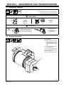
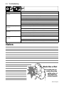
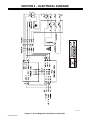
1
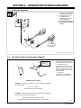
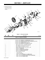
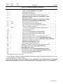
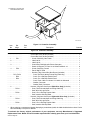
OM-4414
209 141H
2006−07
Description
Belt/Hydraulic-Driven Generator For
Welding Power Sources
Belt-Drive Generator
Hydraulic-Drive Generator
Visit our website at
www.MillerWelds.com
TABLE OF CONTENTS
SECTION 1 − SAFETY PRECAUTIONS − READ BEFORE USING . . . . . . . . . . . . . . . . . . . . . . . . . . . . . . . . . . 1
1-1. Symbol Usage . . . . . . . . . . . . . . . . . . . . . . . . . . . . . . . . . . . . . . . . . . . . . . . . . . . . . . . . . . . . . . . . . . . . . . . . 1
1-2. Arc Welding Hazards . . . . . . . . . . . . . . . . . . . . . . . . . . . . . . . . . . . . . . . . . . . . . . . . . . . . . . . . . . . . . . . . . . 1
1-3. Engine Hazards . . . . . . . . . . . . . . . . . . . . . . . . . . . . . . . . . . . . . . . . . . . . . . . . . . . . . . . . . . . . . . . . . . . . . . 2
1-4. Compressed Air Hazards . . . . . . . . . . . . . . . . . . . . . . . . . . . . . . . . . . . . . . . . . . . . . . . . . . . . . . . . . . . . . . . 3
1-5. Additional Symbols For Installation, Operation, And Maintenance . . . . . . . . . . . . . . . . . . . . . . . . . . . . . 3
1-6. California Proposition 65 Warnings . . . . . . . . . . . . . . . . . . . . . . . . . . . . . . . . . . . . . . . . . . . . . . . . . . . . . . . 4
1-7. Principal Safety Standards . . . . . . . . . . . . . . . . . . . . . . . . . . . . . . . . . . . . . . . . . . . . . . . . . . . . . . . . . . . . . 4
1-8. EMF Information . . . . . . . . . . . . . . . . . . . . . . . . . . . . . . . . . . . . . . . . . . . . . . . . . . . . . . . . . . . . . . . . . . . . . . 4
SECTION 2 − DEFINITIONS . . . . . . . . . . . . . . . . . . . . . . . . . . . . . . . . . . . . . . . . . . . . . . . . . . . . . . . . . . . . . . . . . . . 5
2-1. Symbol Definitions . . . . . . . . . . . . . . . . . . . . . . . . . . . . . . . . . . . . . . . . . . . . . . . . . . . . . . . . . . . . . . . . . . . . 5
SECTION 3 − SPECIFICATIONS . . . . . . . . . . . . . . . . . . . . . . . . . . . . . . . . . . . . . . . . . . . . . . . . . . . . . . . . . . . . . . . . 5
3-1. Description . . . . . . . . . . . . . . . . . . . . . . . . . . . . . . . . . . . . . . . . . . . . . . . . . . . . . . . . . . . . . . . . . . . . . . . . . . 5
3-2. Specifications . . . . . . . . . . . . . . . . . . . . . . . . . . . . . . . . . . . . . . . . . . . . . . . . . . . . . . . . . . . . . . . . . . . . . . . . 5
3-3. Generator Dimensions And Weight . . . . . . . . . . . . . . . . . . . . . . . . . . . . . . . . . . . . . . . . . . . . . . . . . . . . . . . 6
3-4. Controller Dimensions And Weight . . . . . . . . . . . . . . . . . . . . . . . . . . . . . . . . . . . . . . . . . . . . . . . . . . . . . . . 6
3-5. AC Power Curve . . . . . . . . . . . . . . . . . . . . . . . . . . . . . . . . . . . . . . . . . . . . . . . . . . . . . . . . . . . . . . . . . . . . . . 7
SECTION 4 − MAINTENANCE AND TROUBLESHOOTING . . . . . . . . . . . . . . . . . . . . . . . . . . . . . . . . . . . . . . . . 8
4-1. Maintenance Schedule . . . . . . . . . . . . . . . . . . . . . . . . . . . . . . . . . . . . . . . . . . . . . . . . . . . . . . . . . . . . . . . . . 8
4-2. Overload Protection . . . . . . . . . . . . . . . . . . . . . . . . . . . . . . . . . . . . . . . . . . . . . . . . . . . . . . . . . . . . . . . . . . . 8
4-3. Troubleshooting . . . . . . . . . . . . . . . . . . . . . . . . . . . . . . . . . . . . . . . . . . . . . . . . . . . . . . . . . . . . . . . . . . . . . . 9
SECTION 5 − ELECTRICAL DIAGRAM . . . . . . . . . . . . . . . . . . . . . . . . . . . . . . . . . . . . . . . . . . . . . . . . . . . . . . . . . . 10
SECTION 6 − GENERATOR POWER GUIDELINES . . . . . . . . . . . . . . . . . . . . . . . . . . . . . . . . . . . . . . . . . . . . . . . 11
SECTION 7 − PARTS LIST . . . . . . . . . . . . . . . . . . . . . . . . . . . . . . . . . . . . . . . . . . . . . . . . . . . . . . . . . . . . . . . . . . . . . 16
SECTION 1 − SAFETY PRECAUTIONS − READ BEFORE USING
rom _nd_8/03
Warning: Protect yourself and others from injury — read and follow these precautions.
1-1. Symbol Usage
Means Warning! Watch Out! There are possible hazards
with this procedure! The possible hazards are shown in
the adjoining symbols.
Marks a special safety message.
Means “Note”; not safety related.
This group of symbols means Warning! Watch Out! possible
ELECTRIC SHOCK, MOVING PARTS, and HOT PARTS hazards.
Consult symbols and related instructions below for necessary actions
to avoid the hazards.
1-2. Arc Welding Hazards
Use only well-maintained equipment. Repair or replace damaged parts at
once. Maintain unit according to manual.
Wear a safety harness if working above floor level.
Keep all panels and covers securely in place.
Only qualified persons should install, operate, maintain, and repair this unit.
Clamp work cable with good metal-to-metal contact to workpiece or worktable as near the weld as practical.
During operation, keep everybody, especially children, away.
Insulate work clamp when not connected to workpiece to prevent contact
with any metal object.
Do not connect more than one electrode or work cable to any single weld
output terminal.
The symbols shown below are used throughout this manual to
call attention to and identify possible hazards. When you see the
symbol, watch out, and follow the related instructions to avoid the
hazard. The safety information given below is only a summary of
the more complete safety information found in the Safety Standards listed in Section 1-7. Read and follow all Safety Standards.
ELECTRIC SHOCK can kill.
Touching live electrical parts can cause fatal shocks or
severe burns. The electrode and work circuit is electrically
live whenever the output is on. The input power circuit and
machine internal circuits are also live when power is on. In semiautomatic or
automatic wire welding, the wire, wire reel, drive roll housing, and all metal
parts touching the welding wire are electrically live. Incorrectly installed or
improperly grounded equipment is a hazard.
Do not touch live electrical parts.
Wear dry, hole-free insulating gloves and body protection.
Insulate yourself from work and ground using dry insulating mats or covers
big enough to prevent any physical contact with the work or ground.
Do not use AC output in damp areas, if movement is confined, or if there is a
danger of falling.
Use AC output ONLY if required for the welding process.
If AC output is required, use remote output control if present on unit.
Additional safety precautions are required when any of the following electrically hazardous conditions are present: in damp locations or while wearing
wet clothing; on metal structures such as floors, gratings, or scaffolds;
when in cramped positions such as sitting, kneeling, or lying; or when there
is a high risk of unavoidable or accidental contact with the workpiece or
ground. For these conditions, use the following equipment in order presented: 1) a semiautomatic DC constant voltage (wire) welder, 2) a DC manual
(stick) welder, or 3) an AC welder with reduced open-circuit voltage. In most
situations, use of a DC, constant voltage wire welder is recommended.
And, do not work alone!
Disconnect input power or stop engine before installing or servicing this
equipment. Lockout/tagout input power according to OSHA 29 CFR
1910.147 (see Safety Standards).
Properly install and ground this equipment according to its Owner’s Manual
and national, state, and local codes.
Always verify the supply ground — check and be sure that input power cord
ground wire is properly connected to ground terminal in disconnect box or
that cord plug is connected to a properly grounded receptacle outlet.
When making input connections, attach proper grounding conductor first −
double-check connections.
Frequently inspect input power cord for damage or bare wiring — replace
cord immediately if damaged — bare wiring can kill.
Turn off all equipment when not in use.
Do not use worn, damaged, undersized, or poorly spliced cables.
Do not drape cables over your body.
If earth grounding of the workpiece is required, ground it directly with a separate cable.
Do not touch electrode if you are in contact with the work, ground, or another electrode from a different machine.
SIGNIFICANT DC VOLTAGE exists in inverters after stopping engine.
Stop engine on inverter and discharge input capacitors according to
instructions in Maintenance Section before touching any parts.
FUMES AND GASES can be hazardous.
Welding produces fumes and gases. Breathing these fumes
and gases can be hazardous to your health.
Keep your head out of the fumes. Do not breathe the fumes.
If inside, ventilate the area and/or use exhaust at the arc to remove welding
fumes and gases.
If ventilation is poor, use an approved air-supplied respirator.
Read the Material Safety Data Sheets (MSDSs) and the manufacturer’s
instructions for metals, consumables, coatings, cleaners, and degreasers.
Work in a confined space only if it is well ventilated, or while wearing an airsupplied respirator. Always have a trained watchperson nearby. Welding
fumes and gases can displace air and lower the oxygen level causing injury
or death. Be sure the breathing air is safe.
Do not weld in locations near degreasing, cleaning, or spraying operations.
The heat and rays of the arc can react with vapors to form highly toxic and
irritating gases.
Do not weld on coated metals, such as galvanized, lead, or cadmium plated
steel, unless the coating is removed from the weld area, the area is well
ventilated, and if necessary, while wearing an air-supplied respirator. The
coatings and any metals containing these elements can give off toxic fumes
if welded.
BUILDUP OF GAS can injure or kill.
Shut off shielding gas supply when not in use.
Always ventilate confined spaces or use approved
air-supplied respirator.
ARC RAYS can burn eyes and skin.
Arc rays from the welding process produce intense visible
and invisible (ultraviolet and infrared) rays that can burn eyes
and skin. Sparks fly off from the weld.
Wear a welding helmet fitted with a proper shade of filter to protect your face
and eyes from arc rays and sparks when welding or watching (see ANSI
Z49.1 and Z87.1 listed in Safety Standards).
Wear approved safety glasses with side shields under your helmet.
Use protective screens or barriers to protect others from flash and glare;
warn others not to watch the arc.
Wear protective clothing made from durable, flame-resistant material (wool
and leather) and foot protection.
OM-4414 Page 1
WELDING can cause fire or explosion.
HOT PARTS can cause severe burns.
Welding on closed containers, such as tanks, drums, or
pipes, can cause them to blow up. Sparks can fly off from the
welding arc. The flying sparks, hot workpiece, and hot
equipment can cause fires and burns. Accidental contact of electrode to metal
objects can cause sparks, explosion, overheating, or fire. Check and be sure
the area is safe before doing any welding.
Protect yourself and others from flying sparks and hot metal.
Do not weld where flying sparks can strike flammable material.
Remove all flammables within 35 ft (10.7 m) of the welding arc. If this is not
possible, tightly cover them with approved covers.
Be alert that welding sparks and hot materials from welding can easily go
through small cracks and openings to adjacent areas.
Watch for fire, and keep a fire extinguisher nearby.
Be aware that welding on a ceiling, floor, bulkhead, or partition can cause
fire on the hidden side.
Do not weld on closed containers such as tanks, drums, or pipes, unless
they are properly prepared according to AWS F4.1 (see Safety Standards).
Connect work cable to the work as close to the welding area as practical to
prevent welding current from traveling long, possibly unknown paths and
causing electric shock and fire hazards.
Do not use welder to thaw frozen pipes.
Remove stick electrode from holder or cut off welding wire at contact tip
when not in use.
Wear oil-free protective garments such as leather gloves, heavy shirt, cuffless trousers, high shoes, and a cap.
Remove any combustibles, such as a butane lighter or matches, from your
person before doing any welding.
Follow requirements in OSHA 1910.252 (a) (2) (iv) and NFPA 51B for hot
work and have a fire watcher and extinguisher nearby.
FLYING METAL can injure eyes.
Welding, chipping, wire brushing, and grinding cause
sparks and flying metal. As welds cool, they can
throw off slag.
Wear approved safety glasses with side shields even
under your welding helmet.
Allow cooling period before maintaining.
Wear protective gloves and clothing when working on
a hot engine.
Do not touch hot engine parts or just-welded parts
bare-handed.
NOISE can damage hearing.
Noise from some processes or equipment can damage
hearing.
Wear approved ear protection if noise level is high.
MAGNETIC FIELDS can affect pacemakers.
Pacemaker wearers keep away.
Wearers should consult their doctor before going
near arc welding, gouging, or spot welding operations.
CYLINDERS can explode if damaged.
Shielding gas cylinders contain gas under high pressure. If
damaged, a cylinder can explode. Since gas cylinders are
normally part of the welding process, be sure to treat them
carefully.
Protect compressed gas cylinders from excessive heat, mechanical
shocks, slag, open flames, sparks, and arcs.
Install cylinders in an upright position by securing to a stationary support or
cylinder rack to prevent falling or tipping.
Keep cylinders away from any welding or other electrical circuits.
Never drape a welding torch over a gas cylinder.
Never allow a welding electrode to touch any cylinder.
Never weld on a pressurized cylinder — explosion will result.
Use only correct shielding gas cylinders, regulators, hoses, and fittings designed for the specific application; maintain them and associated parts in
good condition.
Turn face away from valve outlet when opening cylinder valve.
Keep protective cap in place over valve except when cylinder is in use or
connected for use.
Read and follow instructions on compressed gas cylinders, associated
equipment, and CGA publication P-1 listed in Safety Standards.
1-3. Engine Hazards
MOVING PARTS can cause injury.
BATTERY EXPLOSION can BLIND.
Always wear a face shield, rubber gloves, and protective clothing when working on a battery.
Stop engine before disconnecting or connecting battery cables or servicing battery.
Do not allow tools to cause sparks when working on a battery.
Do not use welder to charge batteries or jump start vehicles.
Observe correct polarity (+ and −) on batteries.
Disconnect negative (−) cable first and connect it last.
FUEL can cause fire or explosion.
Stop engine and let it cool off before checking or adding fuel.
Do not add fuel while smoking or if unit is near any
sparks or open flames.
Do not overfill tank — allow room for fuel to expand.
Do not spill fuel. If fuel is spilled, clean up before starting engine.
Dispose of rags in a fireproof container.
Always keep nozzle in contact with tank when fueling.
OM-4414 Page 2
Keep away from fans, belts, and rotors.
Keep all doors, panels, covers, and guards closed
and securely in place.
Stop engine before installing or connecting unit.
Have only qualified people remove guards or covers for maintenance
and troubleshooting as necessary.
To prevent accidental starting during servicing, disconnect negative (−)
battery cable from battery.
Keep hands, hair, loose clothing, and tools away from moving parts.
Reinstall panels or guards and close doors when servicing is finished
and before starting engine.
Before working on generator, remove spark plugs or injectors to keep
engine from kicking back or starting.
Block flywheel so that it will not turn while working on generator components.
STEAM AND HOT COOLANT can burn.
If possible, check coolant level when engine is cold to
avoid scalding.
Always check coolant level at overflow tank, if present on unit, instead of radiator (unless told otherwise
in maintenance section or engine manual).
If the engine is warm, checking is needed, and there is no overflow tank,
follow the next two statements.
Wear safety glasses and gloves and put a rag over radiator cap.
Turn cap slightly and let pressure escape slowly before completely removing cap.
ENGINE EXHAUST GASES can kill.
Use equipment outside in open, well-ventilated areas.
If used in a closed area, vent engine exhaust outside
and away from any building air intakes.
BATTERY ACID can BURN SKIN and EYES.
Do not tip battery.
Replace damaged battery.
Flush eyes and skin immediately with water.
ENGINE HEAT can cause fire.
Do not locate unit on, over, or near combustible
surfaces or flammables.
Keep exhaust and exhaust pipes way from flammables.
EXHAUST SPARKS can cause fire.
Do not let engine exhaust sparks cause fire.
Use approved engine exhaust spark arrestor in required areas — see applicable codes.
1-4. Compressed Air Hazards
BREATHING COMPRESSED AIR can
cause serious injury or death.
Do not use compressed air for breathing.
Use only for cutting, gouging, and tools.
COMPRESSED AIR can cause injury.
Wear approved safety goggles.
Do not direct air stream toward self or others.
TRAPPED AIR PRESSURE AND WHIPPING
HOSES can cause injury.
Release air pressure from tools and system before
servicing, adding or changing attachments, or opening compressor oil drain or oil fill cap.
HOT METAL from air arc cutting and
gouging can cause fire or explosion.
Do not cut or gouge near flammables.
Watch for fire; keep extinguisher nearby.
HOT PARTS can cause burns and injury.
Do not touch hot compressor or air system parts.
Let system cool down before touching or servicing.
READ INSTRUCTIONS.
Read Owner’s Manual before using or servicing unit.
Stop engine and release air pressure before
servicing.
1-5. Additional Symbols For Installation, Operation, And Maintenance
FALLING UNIT can cause injury.
Use lifting eye to lift unit only, NOT running gear, gas
cylinders, trailer, or any other accessories.
Use equipment of adequate capacity to lift and
support unit.
If using lift forks to move unit, be sure forks are long
enough to extend beyond opposite side of unit.
OVERHEATING can damage motors.
Turn off or unplug equipment before starting or stopping engine.
Do not let low voltage and frequency caused by low
engine speed damage electric motors.
Wear a face shield to protect eyes and face.
Shape tungsten electrode only on grinder with proper
guards in a safe location wearing proper face, hand,
and body protection.
Allow cooling period; follow rated duty cycle.
Reduce current or reduce duty cycle before starting
to weld again.
Do not block or filter airflow to unit.
STATIC (ESD) can damage PC boards.
Do not connect 50 or 60 Hertz motors to the 100 Hertz receptacle where
applicable.
FLYING SPARKS can cause injury.
OVERUSE can cause OVERHEATING.
Put on grounded wrist strap BEFORE handling
boards or parts.
Use proper static-proof bags and boxes to store,
move, or ship PC boards.
TILTING OF TRAILER can cause injury.
Use tongue jack or blocks to support weight.
Properly install welding generator onto trailer according to instructions supplied with trailer.
Sparks can cause fires — keep flammables away.
OM-4414 Page 3
READ INSTRUCTIONS.
Use only genuine MILLER/Hobart replacement
parts.
Perform engine and air compressor (if applicable)
maintenance and service according to this manual
and the engine/air compressor (if applicable) manuals.
H.F. RADIATION can cause interference.
ARC WELDING can cause interference.
High-frequency (H.F.) can interfere with radio navigation, safety services, computers, and communications equipment.
Have only qualified persons familiar with electronic
equipment perform this installation.
The user is responsible for having a qualified electrician
promptly correct any interference problem resulting from the installation.
If notified by the FCC about interference, stop using the equipment at
once.
Have the installation regularly checked and maintained.
Keep high-frequency source doors and panels tightly shut, keep spark
gaps at correct setting, and use grounding and shielding to minimize the
possibility of interference.
Electromagnetic energy can interfere with sensitive
electronic equipment such as microprocessors,
computers, and computer-driven equipment such as
robots.
Be sure all equipment in the welding area is electromagnetically compatible.
To reduce possible interference, keep weld cables as short as possible,
close together, and down low, such as on the floor.
Locate welding operation 100 meters from any sensitive electronic
equipment.
Be sure this welding machine is installed and grounded according to this
manual.
If interference still occurs, the user must take extra measures such as
moving the welding machine, using shielded cables, using line filters, or
shielding the work area.
1-6. California Proposition 65 Warnings
Welding or cutting equipment produces fumes or gases which
contain chemicals known to the State of California to cause
birth defects and, in some cases, cancer. (California Health &
Safety Code Section 25249.5 et seq.)
For Gasoline Engines:
Engine exhaust contains chemicals known to the State of
California to cause cancer, birth defects, or other reproductive
harm.
Battery posts, terminals and related accessories contain lead
and lead compounds, chemicals known to the State of
California to cause cancer and birth defects or other
reproductive harm. Wash hands after handling.
For Diesel Engines:
Diesel engine exhaust and some of its constituents are known
to the State of California to cause cancer, birth defects, and
other reproductive harm.
1-7. Principal Safety Standards
Safety in Welding, Cutting, and Allied Processes, ANSI Standard Z49.1,
from American Welding Society, 550 N.W. LeJeune Rd, Miami FL 33126
(phone: 305-443-9353, website: www.aws.org).
Recommended Safe Practices for the Preparation for Welding and Cutting of Containers and Piping, American Welding Society Standard
AWS F4.1, from American Welding Society, 550 N.W. LeJeune Rd, Miami, FL 33126 (phone: 305-443-9353, website: www.aws.org).
National Electrical Code, NFPA Standard 70, from National Fire Protection Association, P.O. Box 9101, 1 Battery March Park, Quincy, MA
02269-9101 (phone: 617-770-3000, website: www.nfpa.org and www.
sparky.org).
Safe Handling of Compressed Gases in Cylinders, CGA Pamphlet P-1,
from Compressed Gas Association, 1735 Jefferson Davis Highway,
Suite 1004, Arlington, VA 22202-4102 (phone: 703-412-0900, website:
www.cganet.com).
Code for Safety in Welding and Cutting, CSA Standard W117.2, from
Canadian Standards Association, Standards Sales, 178 Rexdale Bou-
levard, Rexdale, Ontario, Canada M9W 1R3 (phone: 800-463-6727 or
in Toronto 416-747-4044, website: www.csa-international.org).
Practice For Occupational And Educational Eye And Face Protection,
ANSI Standard Z87.1, from American National Standards Institute, 11
West 42nd Street, New York, NY 10036–8002 (phone: 212-642-4900,
website: www.ansi.org).
Standard for Fire Prevention During Welding, Cutting, and Other Hot
Work, NFPA Standard 51B, from National Fire Protection Association,
P.O. Box 9101, 1 Battery March Park, Quincy, MA 02269-9101 (phone:
617-770-3000, website: www.nfpa.org and www. sparky.org).
OSHA, Occupational Safety and Health Standards for General Industry, Title 29, Code of Federal Regulations (CFR), Part 1910, Subpart Q,
and Part 1926, Subpart J, from U.S. Government Printing Office, Superintendent of Documents, P.O. Box 371954, Pittsburgh, PA 15250 (there
are 10 Regional Offices—phone for Region 5, Chicago, is
312-353-2220, website: www.osha.gov).
1-8. EMF Information
Considerations About Welding And The Effects Of Low Frequency
Electric And Magnetic Fields
Welding current, as it flows through welding cables, will cause electromagnetic fields. There has been and still is some concern about such
fields. However, after examining more than 500 studies spanning 17
years of research, a special blue ribbon committee of the National
Research Council concluded that: “The body of evidence, in the
committee’s judgment, has not demonstrated that exposure to powerfrequency electric and magnetic fields is a human-health hazard.”
However, studies are still going forth and evidence continues to be
examined. Until the final conclusions of the research are reached, you
may wish to minimize your exposure to electromagnetic fields when
welding or cutting.
OM-4414 Page 4
To reduce magnetic fields in the workplace, use the following
procedures:
1. Keep cables close together by twisting or taping them.
2. Arrange cables to one side and away from the operator.
3. Do not coil or drape cables around your body.
4. Keep welding power source and cables as far away from
operator as practical.
5. Connect work clamp to workpiece as close to the weld as
possible.
About Pacemakers:
Pacemaker wearers consult your doctor first. If cleared by your doctor,
then following the above procedures is recommended.
SECTION 2 − DEFINITIONS
2-1. Symbol Definitions
A
V
Circuit Breaker
Read Operator’s
Manual
Positive
Negative
Alternating Current
(AC)
Output
Hours
Temperature
Protective Earth
(Ground)
Welding Arc
(Electrode)
Work Connection
Voltage Input
Time
h
Amperes
Volts
SECTION 3 − SPECIFICATIONS
3-1. Description
This belt or hydraulically-driven generator supplies ac power to the platform to run tools through an ac receptacle,
and also operate lights, and cutting and welding equipment. All power regulation components are located in a watertight box that is connected by cable to the generator. The generator supplies power when running at the specified
speed with the Power switch on (switch is located on platform). A 3-pole, 30 Amp circuit breaker protects the generator
from overload.
803 233
3-2. Specifications
Drive-Type
Output
Belt-Drive/Pulley
Single-Phase, 6 kVA/kW, 25 A, 120/240 V,
50/60 Hz
10P
1.0
Power Factor
F t
100% Duty Cycle
Hydraulic
Three-Phase 7.5 kVA/kW, 18 A,
240 V, 50/60 Hz,
1.0 Power Factor
100% Duty Cycle
Generator Speed
3000 rpm (50 Hz)
3600 rpm (60 Hz)
OM-4414 Page 5
3-3. Generator Dimensions And Weight
Dimensions
A
20-1/2 in (521 mm)
B
9 in (229 mm)
C
13 in (330 mm)
C
A
Weight
B
110 lb (50 kg)
A belt-driven model is shown.
803 233
3-4. Controller Dimensions And Weight
Dimensions
A
11-1/2 in (292 mm)
B
9-1/2 in (241 mm)
C
4-1/2 in (114 mm)
Weight
C
A
B
10 lb (5 kg)
803 233
OM-4414 Page 6
3-5. AC Power Curve
The ac power curve shows the
power in amperes available from
the generator.
A. 6 kVA/Kw Single-Phase Output
300
AC VOLTS
250
200
150
100
50
0
0
5
10
15
20
25
30
35
40
45
50
AC AMPERES
B. 7.5 kVA/kW Three-Phase Output
300
250
AC VOLTS
200
150
100
50
0
0
5
10
15
20
25
30
35
40
AC AMPERES
209 397 / 209 398
OM-4414 Page 7
SECTION 4 − MAINTENANCE AND TROUBLESHOOTING
4-1. Maintenance Schedule
Stop engine before maintaining.
Service more often if used in severe conditions.
*
To be done by Factory Authorized Service Agent.
Every 250 h
Check Belt
Tension
(Belt-Driven
Models Only)
1/2 in.
(13 mm)
Replace
Unreadable
Labels.
Every 500 h
Blow Out Inside Of
Generator.
During Heavy Service,
Clean Monthly.
Service Welding Generator
Brushes And Slip Rings. Service
More Often In Dirty Conditions.*
4-2. Overload Protection
Stop engine.
When a circuit breaker opens,
it usually indicates a more serious problem exists. Contact
Factory Authorized Service
Agent.
Open cover to access generator.
1
Circuit Breaker CB1
CB1 protects the generator windings from overload. If CB1 opens,
generator output stops.
Close covers before operating unit.
1
803 233
OM-4414 Page 8
4-3. Troubleshooting
Trouble
No generator output at platform
receptacles.
Remedy
Be sure generator control switch is turned on at platform.
Check and secure electrical connections at platform, generator, and control box.
Be sure all equipment is turned off when starting unit.
Reset circuit breaker CB1 (see Section 4-2).
Check connections at receptacle RC3.
Be sure +12 volts dc input voltage is being supplied to control box.
Have Factory Authorized Service Agent check brushes, slip rings, and circuit boards PC1 and PC2.
Low generator output at platform
receptacles.
Verify generator is running at 3600 rpm.
Have Factory Authorized Service Agent check brushes, slip rings, and circuit boards PC1 and PC2.
High generator output at platform
receptacles.
Check control settings on welding equipment.
Verify generator is running at 3600 rpm.
Have Factory Authorized Service Agent check brushes, slip rings, and circuit boards PC1 and PC2.
Erratic generator output at platform
receptacles.
Check and secure electrical connections at platform, generator, and control box.
Verify generator is running at 3600 rpm.
Have Factory Authorized Service Agent check brushes, slip rings, and circuit boards PC1 and PC2.
Notes
Work like a Pro!
Pros weld and cut
safely. Read the
safety rules at
the beginning
of this manual.
OM-4414 Page 9
SECTION 5 − ELECTRICAL DIAGRAM
210 193-C
Figure 5-1. Circuit Diagram For Generator And Controller
OM-4414 Page 10
SECTION 6 − GENERATOR POWER GUIDELINES
6-1. Selecting Equipment
1
2
3
Generator Power Receptacles
− Neutral Bonded To Frame
3-Prong Plug From Case
Grounded Equipment
2-Prong Plug From Double
Insulated Equipment
Do not use 2-prong plug unless equipment is double insulated.
1
2
3
Be sure equipment
has this symbol
and/or wording.
OR
gen_pwr 11/02* − Ref. ST-159 730 / ST-800 577
6-2. How Much Power Does Equipment Require?
1
3
2
1
VOLTS 115
AMPS 4.5
Hz
60
Resistive Load
A light bulb is a resistive load and
requires a constant amount of power.
2
Non-Resistive Load
Equipment with a motor is a non-resistive load and requires approximately six times more power while
starting the motor than when running
(see Section 6-6).
3
3
Rating Data
Rating shows volts and amperes, or
watts required to run equipment.
AMPERES x VOLTS = WATTS
EXAMPLE 1: If a drill uses 4.5 amperes at 115 volts, calculate its running power
requirement in watts.
4.5 A x 115 V = 520 W
The load applied by the drill is 520 watts.
EXAMPLE 2: If three 200 watt flood lamps are used with the drill from Example 1,
add the individual loads to calculate total load.
(200 W + 200 W + 200 W) + 520 W = 1120 W
The total load applied by the three flood lamps and drill is 1120 watts.
S-0623
OM-4414 Page 11
6-3. Approximate Power Requirements For Industrial Motors
Industrial Motors
Split Phase
Capacitor Start-Induction Run
Capacitor Start-Capacitor Run
Fan Duty
Rating
Starting Watts
Running Watts
1/8 HP
1/6 HP
1/4 HP
1/3 HP
1/2 HP
1/3 HP
1/2 HP
3/4 HP
1 HP
1-1/2 HP
2 HP
3 HP
5 HP
1-1/2 HP
5 HP
7-1/2 HP
10 HP
1/8 HP
1/6 HP
1/4 HP
1/3 HP
1/2 HP
800
1225
1600
2100
3175
2020
3075
4500
6100
8200
10550
15900
23300
8100
23300
35000
46700
1000
1400
1850
2400
3500
300
500
600
700
875
720
975
1400
1600
2200
2850
3900
6800
2000
6000
8000
10700
400
550
650
800
1100
6-4. Approximate Power Requirements For Farm/Home Equipment
Farm/Home Equipment
Stock Tank De-Icer
Grain Cleaner
Portable Conveyor
Grain Elevator
Milk Cooler
Milker (Vacuum Pump)
FARM DUTY MOTORS
Std. (e.g. Conveyors,
Feed Augers, Air
Compressors)
High Torque (e.g. Barn
Cleaners, Silo Unloaders,
Silo Hoists, Bunk Feeders)
3-1/2 cu. ft. Mixer
High Pressure 1.8 Gal/Min
Washer 2 gal/min
2 gal/min
Refrigerator or Freezer
Shallow Well Pump
Sump Pump
OM-4414 Page 12
Rating
1/4 HP
1/2 HP
3/4 HP
2 HP
1/3 HP
1/2 HP
3/4 HP
1 HP
1-1/2 HP
2 HP
3 HP
5 HP
1-1/2 HP
5 HP
7-1/2 HP
10 HP
1/2 HP
500 PSI
550 PSI
700 PSI
1/3 HP
1/2 HP
1/3 HP
1/2 HP
Starting Watts
Running Watts
1000
1650
3400
4400
2900
10500
1720
2575
4500
6100
8200
10550
15900
23300
8100
23300
35000
46700
3300
3150
4500
6100
3100
2150
3100
2100
3200
1000
650
1000
1400
1100
2800
720
975
1400
1600
2200
2850
3900
6800
2000
6000
8000
10700
1000
950
1400
1600
800
750
1000
800
1050
6-5. Approximate Power Requirements For Contractor Equipment
Contractor
Hand Drill
Circular Saw
Table Saw
Band Saw
Bench Grinder
Air Compressor
Electric Chain Saw
Electric Trimmer
Electric Cultivator
Elec. Hedge Trimmer
Flood Lights
Submersible Pump
Centrifugal Pump
Floor Polisher
High Pressure Washer
55 gal Drum Mixer
Wet & Dry Vac
Rating
Starting Watts
Running Watts
1/4 in
3/8 in
1/2 in
6-1/2 in
7-1/4 in
8-1/4 in
9 in
10 in
14 in
6 in
8 in
10 in
1/2 HP
1 HP
1-1/2 HP
2 HP
1-1/2 HP, 12 in
2 HP, 14 in
Standard 9 in
Heavy Duty 12 in
1/3 HP
18 in
HID
Metal Halide
Mercury
Sodium
Vapor
400 gph
900 gph
3/4 HP, 16 in
1 HP, 20 in
1/2 HP
3/4 HP
1 HP
1/4 HP
1.7 HP
2-1/2 HP
350
400
600
500
900
1400
4500
6300
2500
1720
3900
5200
3000
6000
8200
10500
1100
1100
350
500
2100
400
125
313
1000
1400
1250
600
900
4500
6100
3150
4500
6100
1900
900
1300
350
400
600
500
900
1400
1500
1800
1100
720
1400
1600
1000
1500
2200
2800
1100
1100
350
500
700
400
100
250
1000
200
500
1400
1600
950
1400
1600
700
900
1300
OM-4414 Page 13
6-6. Power Required To Start Motor
4
1
3
AC MOTOR
VOLTS 230
AMPS 2.5
CODE M
Hz
60
HP
1/4
PHASE 1
1
2
3
4
2
Motor Start Code
Running Amperage
Motor HP
Motor Voltage
To find starting amperage:
Step 1: Find code and use table to
find kVA/HP. If code is not listed,
multiply running amperage by six to
find starting amperage.
Step 2: Find Motor HP and Volts.
Step 3: Determine starting amperage (see example).
Welding generator amperage output must be at least twice the
motor’s running amperage.
Single-Phase Induction Motor Starting Requirements
Motor Start
Code
G
H
J
K
L
M
N
P
KVA/HP
6.3
7.1
8.0
9.0
10.0
11.2
12.5
14.0
kVA/HP x HP x 1000
VOLTS
= STARTING AMPERAGE
EXAMPLE: Calculate the starting amperage required for a 230 V, 1/4
HP motor with a motor start code of M.
Volts = 230
HP = 1/4
Using Table, Code M results in kVA/HP = 11.2
11.2 x 1/4 x 1000
= 12.2 A Starting the motor requires 12.2 amperes.
230
S-0624
6-7. How Much Power Can Generator Supply?
1
Limit Load To 90% Of
Generator Output
Always start non-resistive (motor)
loads in order from largest to smallest, and add resistive loads last.
2
1
2
5 Second Rule
If motor does not start within 5
seconds, turn off power to prevent
motor damage. Motor requires
more power than generator can
supply.
Ref. ST-800 396-A / S-0625
OM-4414 Page 14
6-8.
Selecting Extension Cord (Use Shortest Cord Possible)
Cord Lengths for 120 Volt Loads
If unit does not have GFCI receptacles, use GFCI-protected extension cord.
Maximum Allowable Cord Length in ft (m) for Conductor Size (AWG)*
Current
(Amperes)
Load (Watts)
5
600
7
840
10
1200
15
4
6
8
10
12
14
350 (106)
225 (68)
137 (42)
100 (30)
400 (122)
250 (76)
150 (46)
100 (30)
62 (19)
400 (122)
275 (84)
175 (53)
112 (34)
62 (19)
50 (15)
1800
300 (91)
175 (53)
112 (34)
75 (23)
37 (11)
30 (9)
20
2400
225 (68)
137 (42)
87 (26)
50 (15)
30 (9)
25
3000
175 (53)
112 (34)
62 (19)
37 (11)
30
3600
150 (46)
87 (26)
50 (15)
37 (11)
35
4200
125 (38)
75 (23)
50 (15)
40
4800
112 (34)
62 (19)
37 (11)
45
5400
100 (30)
62 (19)
50
6000
87 (26)
50 (15)
*Conductor size is based on maximum 2% voltage drop
Cord Lengths for 240 Volt Loads
If unit does not have GFCI receptacles, use GFCI-protected extension cord.
Maximum Allowable Cord Length in ft (m) for Conductor Size (AWG)*
Current
(Amperes)
Load (Watts)
5
1200
7
1680
10
2400
15
4
6
8
10
12
14
700 (213)
450 (137)
225 (84)
200 (61)
800 (244)
500 (152)
300 (91)
200 (61)
125 (38)
800 (244)
550 (168)
350 (107)
225 (69)
125 (38)
100 (31)
3600
600 (183)
350 (107)
225 (69)
150 (46)
75 (23)
60 (18)
20
4800
450 (137)
275 (84)
175 (53)
100 (31)
60 (18)
25
6000
350 (107)
225 (69)
125 (38)
75 (23)
30
7000
300 (91)
175 (53)
100 (31)
75 (23)
35
8400
250 (76)
150 (46)
100 (31)
40
9600
225 (69)
125 (38)
75 (23)
45
10,800
200 (61)
125 (38)
50
12,000
175 (53)
100 (31)
*Conductor size is based on maximum 2% voltage drop
OM-4414 Page 15
SECTION 7 − PARTS LIST
Hardware is common and
not available unless listed.
Actual parts may vary from
illustration.
17
15
16
14
12
13
11
23
10
18
9
24
19
6
5
28
8
7
27
20
1
25
26
2 4
22
21
803 235−C
3
Item
No.
Dia.
Mkgs.
Part
No.
Figure 7-1. Generator Assembly
Description
Quantity
Figure 7-1. Generator Assembly
...................
...................
...................
...................
... 1 .............
... 2 .............
... 3 .............
... 4 .............
... 5 .............
... 5 .............
... 5 .............
... 6 .............
... 7 .............
... 8 .............
... 9 ...........
... 9 ...........
... 9 ...........
OM-4414 Page 16
. . Generator Assy, Belt-Drive, Cat (Mitsubishi) (includes) . . . . . . . . . . . . .
. . Generator Assy, Belt-Drive, Deutz, Ford, Cat (Perkins) (includes) . . . .
. . Generator Assy, Hydraulic-Drive (includes) . . . . . . . . . . . . . . . . . . . . . . . .
. . Generator Assy, Belt-Drive, Cat (Turbo) (includes) . . . . . . . . . . . . . . . . . .
. . . . Key, Stl .250 X .250 X 1.750 (Belt-Drive Only) . . . . . . . . . . . . . . . . . . . . .
. . . . Ring, Rtng Int 2.000 Groove Dia X .064 Thk . . . . . . . . . . . . . . . . . . . . . .
. . . . Ring, Rtng Ext 1.000 Shaft X .042 Thk . . . . . . . . . . . . . . . . . . . . . . . . . . .
. . . . Bearing, Ball Rdl Sgl Row .984 X 2.047 X .591 . . . . . . . . . . . . . . . . . . . .
. . . . Endbell, Gen Belt-Drive . . . . . . . . . . . . . . . . . . . . . . . . . . . . . . . . . . . . . . . .
. . . . Endbell, Gen Belt-Drive, Cat (Turbo) . . . . . . . . . . . . . . . . . . . . . . . . . . . .
. . . . Endbell, Gen Hydraulic-Drive Only . . . . . . . . . . . . . . . . . . . . . . . . . . . . .
. . . . Rotor, Generator (includes) . . . . . . . . . . . . . . . . . . . . . . . . . . . . . . . . . . . . .
. . . . . . Fan, Rotor Gen . . . . . . . . . . . . . . . . . . . . . . . . . . . . . . . . . . . . . . . . . . . . .
. . . . . . Bearing, Ball Radial . . . . . . . . . . . . . . . . . . . . . . . . . . . . . . . . . . . . . . . . . .
. . . . +Stator, Generator Belt-Drive, Cat (Mitsubishi) . . . . . . . . . . . . . . . . . . .
. . . . +Stator, Generator Belt-Drive Deutz, Ford, Cat (Perkins) . . . . . . . . . .
. . . . +Stator, Generator Hydraulic-Drive . . . . . . . . . . . . . . . . . . . . . . . . . . . . .
1
1
1
1
1
1
1
1
1
1
1
1
1
1
1
1
1
Item
No.
Dia.
Mkgs.
Part
No.
Description
Quantity
Figure 7-1. Generator Assembly (Continued)
...
...
...
...
9
10
11
12
...........
.............
.............
.............
. . . 13 . . . . . . . . . . . . .
. . . 13 . . . . . . . . . . . . .
. . . 14 . . . . TE1 . . .
. . . 15 . . . . CB1 . . .
. . . 16 . . . . . . . . . . . . .
. . . 17 . . . . . . . . . . . . .
. . . . . . . . . . RC4 . . .
. . . 18 . . . . . . . . . . . . .
. . . 19 . . . . . . . . . . . . .
. . . 19 . . . . . . . . . . . . .
. . . 20 . . . . . . . . . . . . .
. . . 21 . . . . . . . . . . . . .
. . . 22 . . . . . . . . . . . . .
. . . 23 . . . . . . . . . . . . .
. . . 23 . . . . . . . . . . . . .
. . . 23 . . . . . . . . . . . . .
. . . 24 . . . . . . . . . . . . .
. . . 25 . . . . . . . . . . . .
. . . 26 . . . . . . . . . . . .
............
............
............
.............
....
....
....
....
+Stator, Generator Belt-Drive, Cat (Turbo) . . . . . . . . . . . . . . . . . . . . . . .
Endbell, Gen Brush Block . . . . . . . . . . . . . . . . . . . . . . . . . . . . . . . . . . . . . .
Brushholder Assy, Generator . . . . . . . . . . . . . . . . . . . . . . . . . . . . . . . . . . .
Clamp, Nyl .750 Clamp Dia X.500 Wide .203 Mtg Hole
Belt/Hydraulic-Drive Deutz, Ford, Cat (Perkins) (Turbo) . . . . . . . . . .
. . . . Shroud Assy, Endbell
Belt/Hydraulic-Drive Deutz, Ford, Cat (Perkins) (Turbo) . . . . . . . . . .
. . . . Shroud Assy, Endbell Belt-Drive Cat (Mitsubishi) . . . . . . . . . . . . . . . . .
. . . . Block, Stud Connection 6 Position . . . . . . . . . . . . . . . . . . . . . . . . . . . . . . .
. . . . Circuit Breaker, Man Reset 3p 30a 250vac . . . . . . . . . . . . . . . . . . . . . . .
. . . . Boot, Circuit Breaker 3 Pole W/Bezel And Hardware . . . . . . . . . . . . . . .
. . . . Connector, W/Leads (includes) . . . . . . . . . . . . . . . . . . . . . . . . . . . . . . . . . .
. . . . . . Conn, Rect Univ 084 6p/S 3row Rcpt Cable/Panel Lkg . . . . . . . . . . .
. . . . Conn, Clamp Cable 1.250 . . . . . . . . . . . . . . . . . . . . . . . . . . . . . . . . . . . . . .
. . . . Panel, End Shroud . . . . . . . . . . . . . . . . . . . . . . . . . . . . . . . . . . . . . . . . . . . .
. . . . Panel, End Shroud Belt-Drive Cat (Mitsubishi) . . . . . . . . . . . . . . . . . . .
. . . . Nut, 250−20 .50hex .39h Stl Pld Elastic Stop Nut . . . . . . . . . . . . . . . . .
. . . . Stud, Stl .250−20 X 12.875 . . . . . . . . . . . . . . . . . . . . . . . . . . . . . . . . . . . . .
. . . . Label, Warning Moving Parts Can Cause Serious Injury . . . . . . . . . . . .
. . . . Pulley, Drive 1.694 In Bore, 4 Bolt Pat (Belt-Drive Only) Deutz . . . . . .
. . . . Pulley, Drive 1.688 In Bore, 3 Bolt Pat (Belt-Drive Only) Cat/Perkins
. . . . Pulley, Drive 1.688 In Bore, 4 Bolt Pat
(Belt-Drive Only) Mitsubishi, Turbo . . . . . . . . . . . . . . . . . . . . . . . . . . . .
. . . . Label, Label,Term Mkg Connections . . . . . . . . . . . . . . . . . . . . . . . . . . . . . .
. . *Bushing, Stl .938 Id X 1.625 Od X 1.000 Lg (Belt-Drive Only) . . . . . . . . .
. . *Pulley, Generator 4.88 Dia (60 Hz Belt-Drive Only)
Deutz, Mitsubishi, Turbo . . . . . . . . . . . . . . . . . . . . . . . . . . . . . . . . . . . . . . . .
. . *Pulley, Generator 5.63 Dia (50 Hz Belt-Drive Only) Deutz . . . . . . . . . . .
. . *Pulley, Generator 3.00 Pitch Dia (50 Hz Belt-Drive Only) Ford . . . . . . .
. . *Tensioner, Belt W/Pully (Belt-Drive Only) . . . . . . . . . . . . . . . . . . . . . . . . . .
. . . . Protector, Lead Mylar . . . . . . . . . . . . . . . . . . . . . . . . . . . . . . . . . . . . . . . . . .
1
1
1
1
1
1
1
1
1
1
1
1
1
1
4
4
1
1
1
1
1
1
1
1
1
1
1
...
...
...
...
26
26
27
28
*
Not included in generator assembly.
+
When ordering a component originally displaying a precautionary label, the label should also be ordered. Order
label individually or as part of Label Kit.
To maintain the factory original performance of your equipment, use only Manufacturer’s Suggested
Replacement Parts. Model and serial number required when ordering parts from your local distributor.
OM-4414 Page 17
3
Hardware is common and
not available unless listed.
1
5
Item
No.
Dia.
Mkgs.
Part
No.
2
4
Ref. 803 236
Figure 7-2. Controller Assembly
Description
Quantity
Figure 7-2. Controller Assembly
...................
...................
. . . 1 . . . . PC1 . . .
... 2 .............
...................
... 3 ...........
...................
. . . 4 . . . . PC2 . . .
...................
...................
. . . . . . . RC1, RC14
. . . . . . . . . . RC2 . . .
. . . . . . . . . . RC3 . . .
...................
...................
...................
... 5 .............
. . . . . . . . . . PLG4 . . .
...................
. . . . . . . . . . PLG2 . . .
...................
... 5 .............
. . . . . . . . . . PLG4 . . .
...................
. . . . . . . . . . PLG2 . . .
...................
+
. . Control Box, Assy 60 Hz (includes) . . . . . . . . . . . . . . . . . . . . . . . . . . . . . . . .
. . Control Box, Assy 50 Hz (includes) . . . . . . . . . . . . . . . . . . . . . . . . . . . . . . . .
. . . . Circuit Card Assy, Gen Power . . . . . . . . . . . . . . . . . . . . . . . . . . . . . . . . . . .
. . . . Label, 60 Hz . . . . . . . . . . . . . . . . . . . . . . . . . . . . . . . . . . . . . . . . . . . . . . . . . .
. . . . Label, 50 Hz . . . . . . . . . . . . . . . . . . . . . . . . . . . . . . . . . . . . . . . . . . . . . . . . . .
. . . . Control Box, Belt/Hydraulic-Driven Generator . . . . . . . . . . . . . . . . . . . . .
. . . . Stand−off Support, PC Card .312/.375w/Post&lock .43 . . . . . . . . . . . . .
. . . . Circuit Card Assy, Control . . . . . . . . . . . . . . . . . . . . . . . . . . . . . . . . . . . . . .
. . . . Panel, Mtg PC Card . . . . . . . . . . . . . . . . . . . . . . . . . . . . . . . . . . . . . . . . . . .
. . . . Harness, Wrg Control Box (Not Shown) (includes) . . . . . . . . . . . . . . . . .
. . . . . . Conn, Rect Univ 084 9p/S 3row Plug Cable Lkg . . . . . . . . . . . . . . . . .
. . . . . . Conn, Circ 6 Skt Rcpt Pushin Panel . . . . . . . . . . . . . . . . . . . . . . . . . . . .
. . . . . . Conn, Circ 3 Skt Rcpt Pushin Panel . . . . . . . . . . . . . . . . . . . . . . . . . . . .
. . . . . . Conn, Push 4 Wire 12−16strnd 12−18sld 16−22tinstrnd . . . . . . . . . . .
. . . . . . Gasket, Connector . . . . . . . . . . . . . . . . . . . . . . . . . . . . . . . . . . . . . . . . . .
. . . . . . Gasket (Seal), Connector . . . . . . . . . . . . . . . . . . . . . . . . . . . . . . . . . . . . .
. . Harness, Wrg Inter Gen/Control (Belt-Drive Only) (includes) . . . . . . . . . .
. . . . Conn, Rect Univ 084 6p/S 3row Plug Cable Lkg . . . . . . . . . . . . . . . . . . .
. . . . Seal, Wire Univ 6p/S 3row . . . . . . . . . . . . . . . . . . . . . . . . . . . . . . . . . . . . .
. . . . Conn, Circ 6 Skt Plug Pushin Cable . . . . . . . . . . . . . . . . . . . . . . . . . . . . .
. . . . Seal, Interface Univ 6p/3Row . . . . . . . . . . . . . . . . . . . . . . . . . . . . . . . . . . . .
. . Harness, Wrg Inter Gen/Control (Hydraulic-Drive Only) (includes) . . . .
. . . . Conn, Rect Univ 084 6p/S 3row Plug Cable Lkg . . . . . . . . . . . . . . . . . . .
. . . . Seal, Wire Univ 6p/S 3row . . . . . . . . . . . . . . . . . . . . . . . . . . . . . . . . . . . . .
. . . . Conn, Circ 6 Skt Plug Pushin Cable . . . . . . . . . . . . . . . . . . . . . . . . . . . . .
. . . . Seal, Interface Univ 6p/3Row . . . . . . . . . . . . . . . . . . . . . . . . . . . . . . . . . . . .
1
1
1
1
1
1
8
1
1
1
2
1
1
2
1
1
1
1
1
1
1
1
1
1
1
1
When ordering a component originally displaying a precautionary label, the label should also be ordered. Order
label individually or as part of Label Kit.
To maintain the factory original performance of your equipment, use only Manufacturer’s Suggested
Replacement Parts. Model and serial number required when ordering parts from your local distributor.
OM-4414 Page 18
Notes
OM-4414 Page 19
Notes
MATERIAL THICKNESS REFERENCE CHART
24 Gauge (.025 in)
22 Gauge (.031 in)
20 Gauge (.037 in)
18 Gauge (.050 in)
16 Gauge (.063 in)
14 Gauge (.078 in)
1/8 in (.125 in)
3/16 in (.188 in)
1/4 in (.25 in)
5/16 in (.313 in)
3/8 in (.375 in)
1/2 in (.5 in)
OM-4414 Page 20
Owner’s Record
Please complete and retain with your personal records.
Model Name
Serial/Style Number
Purchase Date
(Date which equipment was delivered to original customer.)
Distributor
Address
City
State
Zip
For Generator Service
Call 1−877−554−5438 to contact JLG Service.
Always provide Model Name and Serial/Style Number.
Contact your Miller Distributor for:
Miller Electric Mfg. Co.
An Illinois Tool Works Company
1635 West Spencer Street
Appleton, WI 54914 USA
International Headquarters−USA
USA Phone: 920-735-4505 Auto-Attended
USA & Canada FAX: 920-735-4134
International FAX: 920-735-4125
European Headquarters −
United Kingdom
Phone: 44 (0) 1204-593493
FAX: 44 (0) 1204-598066
www.MillerWelds.com
Contact the Delivering Carrier to:
Welding Supplies and Consumables
Options and Accessories
Personal Safety Equipment
Service and Repair
Replacement Parts
Training (Schools, Videos, Books)
Technical Manuals (Servicing Information
and Parts)
Circuit Diagrams
Welding Process Handbooks
File a claim for loss or damage during
shipment.
For assistance in filing or settling claims, contact
your distributor and/or equipment manufacturer’s
Transportation Department.
PRINTED IN USA
© 2004 Miller Electric Mfg. Co.
1/03