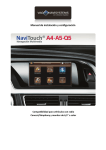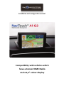
1
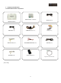
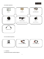
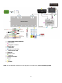
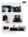
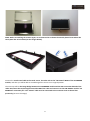
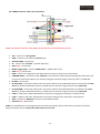
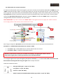
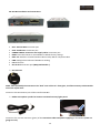
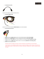
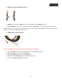
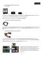
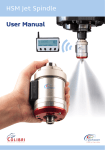
Installation and configuration manual Compatibility with vehicles which have a Concert RMC Radio and a 6,5” colour display Index 1. Component identification – Page.3 1.1. Multimedia interface components– Page.3 1.2. GPS Box components – Page.4 1.3. Voice module components – Page.4 2. Installation – Page.5 2.1. Multimedia interface installation diagram – Page.5 2.2. Setting up the multimedia interface before installing it – Page.6 2.3. Multimedia interface installation and connections– Page.7 2.4. POWER connector cables and connections – Page.11 2.5. Aftermarket rear camera connection – Page.12 2.6. GPS Box installation and connections – Page.13 2.7. Voice module installation and connections – Page.16 2.8. Linking up the interface GPS Box and the multimedia interface – Page.17 3. GPS Box Configuration – System Configuration – Page.18 3.1. Calibrating touch and adjusting the image – Page.18 3.2. RESET – Page.21 3.3. Maps SD card and GPS signal – Page.22 3.4. Checking the GPS signal – Page.23 4. FAQ’S/Solving problems – Page.24 1 Basic knowledge before installation: • Please, read fully and carefully this installation handbook before you attempt to install the kit in your vehicle. • Start the installation once you have the car stopped and the key out of the ignition slot, supply power must be the last step in installation. • When you connect the product and his accessories cables or connections to the vehicle components, the power cables of the products must be unplugged. • Make sure that there are no electric or magnetic devices near of the installation place. • Installation must be performed by a qualified specialist. • Product losses his warranty if you dismantle it or if you try to fix it without the manufacturer permission. If you break up product security stickers, warranty will be lost too. • Check that you have received all the product components before the installation. If you see any part damaged or faulty, contact us immediately. • Problems made by a user mistake in the installation or manipulation of the product suppose the warranty invalidation. • Vag-Navisystems S.L. WON’T make responsible if the product damages the car or user, caused by a wrong installation or an improper use of the product. You must note the manufacturer regulations for the manipulation of electric components, and the disconnection of the airbags and the dismantling procedures of interiors or pieces needed to perform the installation. 2 1. Component identification: 1.1. Multimedia interface components: Additional module - SUB BOARD IR cable ((4P)*1ea) Multimedia interface MODE cable (*1ea) POWER cable ((24P) *1ea) AV cable (*1ea) TOUCH OUT cable (*1ea) REAR CAMERA POWER cable (*1ea) LVDS cable (*1ea) TOUCH cable (*1ea) Remote Control (*1ea) Original LCD cable HSD (*1ea) (*1ea= 1 unity) 3 1.2. GPS Box components: GPS Box Touch screen GPS Box POWER cable GPS antenna Hidden microphone Speaker (Specific for overhead courtesy lights panel) (Optional installation) USB extension cable 1.3. Voice module components: Voice module Voice module Quadlock cable 2. Installation: 2.1. Multimedia interface installation diagram: 4 Voice module audio cable MULTIMEDIA VIDEO INTERFACE SUB BOARD Navigation - GPS Box Touch cable LVDS cable Original LCD cable HSD Offered Touch cable Monitor Touch Screen Head unit Original LCD cable CAM RCA POWER NOTE: The not identified connections in this diagram or the useless ones, must be isolated/ignorated. 5 2.2. Setting up the multimedia interface before installing it: DIP Switches: Using the DIP Switches of the multimedia interface you will be able to enable/disable the external multimedia devices, Navigation, DVD, rear cameras, etc… anything that you connect. For example, if you are going to connect a multimedia device in the AV1, and another in the AV3, we will just enable the corresponding DIP Switches (DIP2 and DIP 4) and we will disable all the remaining DIP Switches, if we do like this, we will only have that 2 enabled sources in the interface (AV1 and AV3), and when you change from one source to the other, the interface will skip the ones that are disabled. Doing this, we get a faster change between sources. Dip 1 is used for navigation source (RGB connection). See the next sample image: VERY IMPORTANT: DIP Switch UP - Enable / DIP Switch DOWN - Disable (Ignore “ON” inscription) Like this in the sample image: • • • • • • • • DIP 1 - (up) Enabled DIP 2 - (down) Disabled DIP 3 - (down) Disabled DIP 4 - (up) Enabled DIP 5 - (up) Enabled DIP 6 - (up) Enabled DIP 7 - (down) Disabled DIP 8 - (up) Enabled DIP Switches function: • • • • • • • • NaviTOUCH A1 Q3 Configuration: • • • • • • • • • DIP 1 - Up DIP 2 - Down DIP 3 - Down DIP 4 - Down DIP 5 – Up (400 x 240) Down (800 x 480) DIP 6 - Down DIP 7 Up - enable OEM camera/ without rear camera DIP 7 Down - enable aftermarket camera DIP 8 - Down DIP 1 - Enable/disable RGB (GPS Box) DIP 2 - Enable /disable AV1 DIP 3 - Enable /disable AV2 DIP 4 - Enable/ disable AV3 DIP 5 - No function DIP 6 - No function DIP 7 - Enable/disable aftermarket rear camera or OEM DIP Switch 7 up - enable OEM camera/ without rear camera DIP Switch 7 down - enable aftermarket camera DIP 8 - No function 6 2.3. Multimedia interface installation and connections: The first step will be to disassemble the screen from the dashboard, see on the image below. Unplug the switches from the center of the aerators and then unscrew the screw. Leverage the screen’s support using the removal tool 3094. Remove the radio using the removal tools T10057 and disassemble the rear connectors. Now, we are going to remove the auto glove compartment, unscrew the screws from 1 to 4. 7 Disconnect the electric connector of the auto glove compartment, and remove the auto glove compartment. Once you have removed it, you will have enough space to perform the connections between the multimedia interface, the additional module and the vehicle’s screen and you will have too, space to place the multimedia interface. Now we will proceed to place the touch screen. To do that, first we will have to disassemble the frame using a nylon wedge and then we will unscrew the two rear Torx screws. The screen will be removed and then it will be possible to disassemble the front metal frame of the screen. Using a pair of pliers and a wedge we are going to remove the metal frame. Now, remove the screen’s metal frame and clean the screen using a specific cleaning product and a microfiber cloth. Then we will place the touch screen and the screen’s metal frame. NOTE: Don’t tighten too much the metal frame, it only has to be holded. 8 NOTE: Before ensambling the monitor again, we recommend to cut down the outside plastic frame where the touch panel has to be holded (see the images below). Connect the Touch Panel cable to the touch screen, the other side to the ”TO TOUCH” INPUT of the SUB BOARD module, and then you will be able to assemble again the screen on its original position. The next step will be the image bridge between the SUB BOARD module and the HSD connection behind of the radio. Disconnect the Purple Original LCD cable HSD of the radio and connect it to the SUB BOARD module “TO MONITOR” connection port. The “TO SYS” cable must be connected to the connector that we leaved free previously (see it on the image). 9 Then, connect the LVDS cable (*1ea) to the “FROM I/F” connection port of the additional module (SUB BOARD) and connect the other side to the multimedia interface LVDS OUT. 10 2.4. POWER connector cables and connections: NOTE: The supply connection must always be the last step in the installation process. • • • • • • • • • • • • • • • • ACC – Connect to +12V Ignition GND – Connect to the vehicle’s Ground point GPIO-ZO: MMI – No function IR – Connect the “IR cable” - (IR cable (4P)*1ea) PB12 (N.C) – No function MODE: Toggle S/W – Connect “MODE cable” - (MODE cable *1ea) OPT2 (N.C) – No function REAR – Connect to a signal from rear light bulb if you want to install a rear view camera PARKING (SAFE) – Connection cable “optional” to the vehicle’s hand break (Connecting this cable, when you remove the vehicle hand break, you will stop seeing the interface images (“Security mode”) TV FREE OFF IR-NAVI – No function IR-AV1 (DVD) – Connection cable to the “IR control” cable from the multimedia device connected to the RCA AV1 entry of the multimedia interface, to enable his own controls using the touch screen (optional) IR-AV2 (DMB) – Connection cable to the “IR control” cable of the multimedia device connected to the RCA AV2 entry of the multimedia interface, to enable his own controls using the touch screen (optional) CAN H – Cable for the CAN H Infotainment connection (orange-green, Gateway or climate panel) CAN L – Cable for the CAN L Infotainment connection (orange-brown, Gateway o climate panel) RGB – Connect the RGB OUT connector of the GPS Box cables AUX-ON (N.C) – No function NOTE: The manufacturer may change the pins and colors here shown, please check every connection and cable before proceed to install. Insulate the cables that won’t be used. 11 2.5. Aftermarket rear camera connection: To connect an aftermarket camera (not original), you have to connect to the interface multimedia “R-CAM” port, the “CAM” connector that has 2 cables, a red one and a black one. The red one will supply the cam +12V, and the black one to a ground. If you do this way, the multimedia interface will supply power to any camera that you connect. It is very important to do this connection, because if you don’t proceed this way, camera won’t work. You also should connect the RCA video of the camera to the RCA connector “REAR C” and also the “REAR” cable to a signal from rear light bulb if you want to install a rear view camera. VERY IMPORTANT: If you don’t connect the ”REAR” cable to the signal from the rear light, the “CAM” connector won’t supply power to the camera, so the camera won’t work. Don’t forget to adjust the DIP Switch 7 of the multimedia interface once all connections have been done: DIP Switch 7 – Enable/disable aftermarket rear camera or OEM • • DIP Switch 7 Up – enable OEM camera / without aftermarket rear camera DIP Switch 7 Down – enable the aftermarket camera Attention; new Audi cars model year from 2011 to nowadays, rear light signal needs to install a relay to filter signal pulses. Please pay attention to the information below. The rear gear signal mustn’t pass through any box (Filter FUSE BOX) so, you must cut the cables connected to the filter fuse box incoming from the rear gear signal and the output from this. Follow the indications below: - Rear gear bulb signal -> Input no "85" Relay - 12+ ignition -> Input "30" Relay - Ground -> Input "86" Relay - Relay’s output (To the Multimedia interface grey cable) -> Input "87" Relay 12 2.6. GPS Box installation and connections: • • • • • • • • GPS: Antenna GPS connection port USB: USB devices connection port POWER & DATA: Connection and supply cables connection port RESET: Press this button to reset GPS Box to default factory settings RGB – AV: Switcher to switch between video modes, RGB or composite video PWR: LED light that indicates if GPS Box is working CA: No function SD: SD card connection port (Maps, Multimedia…) GPS antenna: NOTE: Place preferably the antenna on the “dark” zone of the car’s front glass, it will be necessary to disassemble one of the A pilar trims. Connect to the GPS antenna port of the interface GPS Box Hidden microphone specific for locate at overhead courtesy lights panel: Connect to the 3.5 Jack connector (green) of the connection cables and power supplying of the GPS Box (if we are going to use it). 13 USB extension cable: Connect to the USB port interface GPS Box of the GPS Box POWER cable: Connect to the interface GPS Box POWER & DATA port interface GPS Box RCA and Jack connectors: • • • • • White Conector: AUDIO L OUT, connect to the left side audio IN of the voice module Red Conector: AUDIO R OUT, connect to the right side audio IN of the voice module Green Conector: Green MIC, jack 3.5mm connection for microphone (if it’s going to be used) Yellow Conector: VIDEO OUT, GPS Box video out connection (if RGB OUT is not being used) Black Conector: IR, No function GPS Box must be accessible to be able to connect the SD card, the placement on the auto glove compartment it’s ok, holded by double face tape or with plastic flanges, will be enough, you also have to make a hole (diameter of about 20mm) on the back of the glove compartment to pass the GPS Box cables through it. 14 RGB OUT and TOUCH SCREEN connectors: • • RGB OUT: Connect to the “RGB” port of the multimedia interface POWER connector TOUCH SCREEN: Connect to the multimedia interface “Touch cable” – (4 wire) (TOUCH OUT cable *1ea) Make sure that you are doing correctly the connection from the GPS Box “TOUCH SCREEN” cable to the multimedia interface “Touch cable” (TOUCH OUT cable *1ea). POWER cables, speaker and mute: NOTE: The POWER connection always must be the last step in installation. • • • • • Black cable: GND, connect to the vehicle’s mass (you must weld, don't braid) Red cable: ACC, connect on +12V ACC ignition Yellow cable: BATT+, connect on +12V ACC ignition White/blue cable: SPEAKER, (Speaker connection, optional) Green cable: AUDIO CONT, (Mute, optional) 15 2.7. Voice module installation and connections: Voice module: fig.1 fig.2 fig.3 Voice Module with a LED Light that indicates that is working (fig. 1), Quadlock cable connection port (fig.2), Jack connection port for the Audio cable connection and volume regulator (fig.3) NOTE: Voice module for the audio signal to the vehicle’s front speakers. Audio connection cable from the voice module: Insert to the voice module the black jack 3.5 type connector, connect the white and the red RCA connectors to the RCA AUDIO L OUT and AUDIO R OUT connectors from the “GPS Box POWER wiring harness” (red to red, white to white). Voice module Quadlock Plug and Play harness: Connect the female Quadlock connector of the Voice module Quadlock Plug and Play harness, to the male Quadlock connector of the vehicle (once you have removed vehicle’s radio), connect the Voice module Quadlock Plug and Play harness male connector to the vehicle’s Power IN connection. In vehicles which have in the Quadlock, the "E" connector (light grey color), it will be necessary to remove the "E" connector from the vehicle's original Quadlock, and place it in the empty hole that will connect to the radio of the supplied wiring harness "Voice module Quadlock Plug and Play harness" 16 Connect the 12 pin White connector to the Voice module Quadlock cable connection port and connect the yellow loose cable to a +12V ACC ignition source. NOTE: The POWER connection always must be the last step in installation. Check that you can switch the screen’s image pushing the NAV button of the multifunction steering wheel. 2.8. Linking up the interface GPS Box and the multimedia interface: To connect the interface GPS Box to the multimedia interface, you must connect the “Touch cable” (4-wire) connector - (TOUCH OUT cable *1ea), to the “TOUCH” connection port of the multimedia interface, now we are going to connect the remaining connector to the GPS Box connector (TOUCH SCREEN cable). Once you have done all connections correctly, you can connect all the power cables of the different component and devices that will be used (always with the vehicle stopped, and with the ignition key out of its port), then, connect again the connectors that you had removed from the radio, and place the radio on its original position, start the vehicle to check if radio works properly. Then we are going to proceed to configure the system for its tune up. Technical specifications GPS Box: Navigation Maps SD Card (it supports SDHC, max.16GB) OS WINCE 6.0 CORE Audio Formats MP3/PCM/WMA Video Formats mp4, mpeg, mpg, asf, wmv, mov, avi, 3gp, 3g2, wm, divx, mkv, ogm, wvx, mpv USB 16GB 17 3. GPS Box Configuration – System Configuration: 3.1. Calibrating touch and setting the image: When starting the vehicle, it will appear on its screen, the OEM original menu image: Don’t insert the SD Card map yet, Push briefly the NAV button of the steering wheel for 2 sec. to enter NAVI mode, Screen’s image will change and it’s going to show NAVI mode (GPS Box) image, wait some seconds, until appears calibration image: Push this cursor “+” on the touch screen, once pushed the + cursor, it will change its position, push it in every zone of the screen where it appears until you receive “OK” message, at this way you will have calibrated successfully the touch screen gps function, if it doesn’t appears “OK” message, you must repeat this process again. Once you have done the calibration process it will appear this message “Unable to find navigation software”, push on this message to omit it. Then you must config. the multimedia interface, push the Menu button of the multimedia interface’s remote control to enter to the basic settings menu, use ▲ or ▼of the remote control to move to OSD and push OK, now push OK on LANGUAGE, use ▲ or ▼ buttons of the remote control to select the English language, and push OK to confirm your selection, then push the Menu button of the remote control until the basic settings menu disappears. 18 Now, push the ◀ button for 5 seconds to enter to the interface advanced settings menu or push the following button combination: ▲→ ▼→ ▲→ MENU. Move the selector to UTIL, using ▲ or ▼ buttons of the remote control and push OK, push OK again on TOUCH CALIBRATION, select YES option by the ▲ or ▼remote control buttons and push OK. Once the OK button is pushed, it will appear the message “CALIBRATION” in the center of the screen, then, screen will show a white wallpaper with a cross shape cursor in the center. Push this cursor for aproximattely 2 sec. in the touch screen, once the cursor "+" is pushed it will change its position, push it in all the screen zones where it appears until you receive the message “SUCCES”, this way you will have calibrated successfully the touch screen, if while you are doing the calibration process appears the message “FAIL”, you must repeat the process again. At this way, you have configured the interface multimedia to be able to change the mode by touching, in NAVI mode, hold on pushing the touch screen until appears the touch mode menu: Push on the OEM touch screen button to enter to the original vehicle OEM's video mode, to go back to NAVI mode from the OEM mode push briefly the touch screen. Now you will have to adjust the screen’s image position, push on the “Settings” button, then push on the “Screen” button, and finally on the “Ajust position” button, this way we will enter to the screen’s setting menu, adjust it using the menu buttons. You can also use the “Adjust Size” button to adjust even more the screen's image. 19 The default settings of the “Adjust Size” menu is the next one: Horizontal 5 & Vertical 7 Once you have adjusted image, you have to calibrate the touch screen again, push on “Settings”, then push on “Touch Screen”, and repeat the steps for calibration process mentioned before. NOTE: Remember to do again a calibration of the touch screen after adjusting the image on the screen. Even if you do this changes and you can’t adjust the image as much as you want, you can use the multimedia interface image setting menu. Now push the ◀ button of the multimedia interface remote control for 2 seconds to enter to the advanced settings menu, this image will be shown: Use ▲ or ▼ buttons of the remote control to select IMAGE in the menu, and push OK to enter. Now use ▲ or ▼ buttons of the remote control to select between the H-POSITION (Horizontal position) and V-POSITION (Vertical position), once you have entered to one of the options, adjust it by using the ▲ or ▼ buttons of the remote control, push OK to confirm. 20 You must check that the MMI control option is ON in the Advanced Settings menu (push the ◀ button for 5 seconds to enter to the interface advanced settings menu or push the following button combination: ▲→ ▼→ ▲→ MENU) Push MENU button of the remote control until the advanced menu settings of the multimedia interface disappears from the screen. Remember to do again a touch calibration after adjusting the screen’s image. Now you can insert the maps SD Card to the GSP Box. 3.2. RESET: If you RESET the GPS Box or the multimedia interface, repeat again the steps from the chapter 3.1, maybe, when you perform a RESET on it, the language of the GPS Box could be changed, follow the next steps to config. it again to your desired language: Make a touch calibration of the GPS Box following the steps described before, now push the “Settings” button, then push the “Usual Setup” button and select the language that you prefer. NOTE: If you change the position of the RGB to AV Switch from the GPS Box (in RGB default position) it will RESET, then follow the steps described before to adjust the system again. 21 3.3. Maps SD card and GPS signal: Once you have insert the Maps SD card, we have to setup the route of the executable file (.exe), follow the next steps: Push on Settings, then in Navigate Setup, uncheck the auto initialitzation software option, and push on the folder icon. Once you have pressed the folder icon, you must search for the .exe file of the SD card, use the menu arrows to move through it, and push OK button to confirm you selection, once you have done this action, it will appear the selected route, then push the X in the right top corner of the screen to go back to the Main Menu of the GPS Box Once you are in the Main Menu push on the Navigation icon to access to the SD card maps 22 3.4. Checking the GPS: Perform these steps on a space with good GPS reception Don't try to perform the steps with the vehicle inside of a building or a garage • • • • • • • • Disconnect the GPS Box antenna In the main menú push on Settings Push on DATOS GPS Push on the third image starting at the top (graph bar) Now connect the GPS antenna Look how many bars rise when you have connected the antenna (wait for some time) from 3 to 5 bars is a normal reception, from 7 to 8 it’s an excellent reception If bars don’t rise, try connecting another GPS antenna, it may be that the connected one isn’t working properly. If you have tried different antennas, and the system is still not working, it may be that the problem is the interface GPS Box If you receive GPS signal with the antenna connected after doing the previous steps, follow the next steps: • • • • • • • • • • • Go back to the GPS Box Main Menu Enter to Navigation, once you are in the Navigation Menu, push on the Settings button Push the button with an arrow on it, that is in the right bottom of the screen Push on GPS Uncheck the “GPS Active” box Push on Auto. Detec. and wait for the final of the process The normal channels that may appear are: port 2 / Caud Baud 38400 and/ or port 0/ Cau Baud 9600 Now, go back to the navigation menu and push on Map Push on an antenna image (antenna and vehicle) in the bottom left part of the map’s screen Push on GPS, and wait for the necessary time until the system receives the satellite signal . If in the “Precisión” box, the precision is mid-high, then there is a good GPS reception and the system works properly 23 4. FAQ’S/Solving problems: 1. ¿Why do I can’t change the interface mode? • Check if the IR cable is connected or not. • Check if the interface red LED light is shining or not. If it isn’t shining, check if the “POWER” connector is right connected. • Check if CAN connections have been done correctly. 2. ¿Why does my screen show up all black? • Check if the interface green LED light is shining or not. If it isn’t shining, check the RGB connections of the devices connected to the multimedia interface, and check that these devices are working properly. • Check that the GPS Box RGB cables are correctly connected. 3. ¿Why do I can’t see the rear’s camera image? • Check the position of the DIP Switch 7, check all the connections from the camera to the interface: “REAR C”, “R-CAM”, “CAM” y “REAR” 4. ¿Why do I have to pass through all the interface’s modes until I get the one I want? • Check that you have disabled the entries of the multimedia devices that you are not going to use, positioning correctly the corresponding DIP PINS of the interface. 5. ¿Why do I can’t see my vehicle screen's original image? • Check if the cables of the original screen of the vehicle are correctly connected. 24