1
HSM Jet Spindle
User Manual
CO L I B R I
S P I N D L E S
T E C H N O L O G Y
Typhoon
HSM Jet Spindles
Table of Contents
1
General
1.1
1.2
1.2.1
1.2.2
1.2.3
1.3
1.4
1.5
1.5.1
1.5.2
1.5.3
1.5.4
1.5.5
Safety First.....................................................................................................................4
Statement of Compliance..............................................................................................5
European standards (CE).................................................................................................5
American standards (UL)..................................................................................................5
International standards.....................................................................................................5
Introduction....................................................................................................................6
Case Contents...............................................................................................................6
Main Features................................................................................................................6
Wireless Rotation Speed Display......................................................................................7-8
Built-in and Direct Mounting System to CNC Spindle.......................................................9
Shaft Locking for Tool Clamping......................................................................................9
Integrated Coolant Nozzle System...................................................................................10
Tool Clamping..................................................................................................................10
2
Installation
2.1
Battery installation into the RPM wireless transmitter.................................................11
2.2
Display............................................................................................................................11
2.2.1
Prerequisite for display installation....................................................................................11
2.2.2
Display Workspace Installation.........................................................................................11
2.2.3Connect...........................................................................................................................12
2.2.4Screens...........................................................................................................................12-17
2.2.5Disconnect......................................................................................................................17
2.3
HSM Jet Spindle............................................................................................................18
2.3.1
Prerequisites for the CNC Machine..................................................................................18
2.3.2
Spindle Installation onto the CNC Machine......................................................................19
2.3.3
Placement of HSM Jet Spindle in Toolholder....................................................................19-20
2.3.4
Prerequisites for Tools......................................................................................................21
2.3.5
Tool Installation into HSM Jet Spindle...............................................................................21-22
2.3.6
Check for Run-Out upon Tool Clamping...........................................................................23
3
Maintenance
3.1
Periodic Maintenance....................................................................................................24
3.2
Battery Change on RPM Transmitter............................................................................24
3.3
Operation Conditions....................................................................................................24
3.4
Storage...........................................................................................................................24
3.4.1Pre-Storage.....................................................................................................................24
3.4.2
Condition for Storage.......................................................................................................24
4
Working with the HSM Jet Spindle
4.1
4.1.2
Recalculating of the Table Feed for HSM Jet spindle..................................................25-26
New Machining Process................................................................................................26
5
Troubleshooting
5.1
5.2
5.3
Display messages..........................................................................................................27
The HSM Jet Spindle shaft does not rotate or RPM does not correspond
correctly to coolant pressure........................................................................................27
The HSM Jet Spindle has not been used in the last month........................................27
6
7
8
Warranty Summary........................................................................................................................ 28-29
Customer Service after Purchase............................................................................ 30
FCC Compliance Statement............................................................................................. 31
Table of Figures
Figure 1: Spindle case content.......................................................................................................5
Figure 2: Display case content........................................................................................................5
Figure 3: Rotation speed vs. tool diameter.....................................................................................6
Figure 4: The relation between coolant pressure & RPM value........................................................6
Figure 5: HSM Jet Spindle wireless transmitter and display............................................................6
Figure 6: Wireless RPM display main view......................................................................................7
Figure 7: Wireless RPM display mounting options..........................................................................7
Figure 8: HSM Jet Spindle with several mounting adaptation types................................................8
Figure 9: HSM Jet Spindle with pin mechanism locked...................................................................8
Figure 10: Integrated coolant nozzel system.....................................................................................9
Figure 11: Overhang solution types................................................................................................9
Figure 12: Battery case open.........................................................................................................10
Figure 13: Switch display ON.........................................................................................................10
Figure 14: Many HSM Jet Spindles can be connected to one display.............................................11
Figure 15: No signal displayed........................................................................................................11
Figure 16: Connection screens.......................................................................................................12
Figure 17: Main display screen.......................................................................................................12
Figure 18: List of connected HSM Jet Spindles display..................................................................13
Figure 19: Disconnection display....................................................................................................14
Figure 20: More than one device is working simultainusly screen....................................................14
Figure 21: Disconnection list for multiple signals screens................................................................14
Figure 22: Disconnect all sensors screens......................................................................................15
Figure 23: Connection failed screen................................................................................................15
Figure 24: Disconnection failed screen...........................................................................................16
Figure 25: Low battery screen........................................................................................................16
Figure 26: Low RPM screen...........................................................................................................16
Figure 27: High RPM screen...........................................................................................................17
Figure 28: HSM Jet Spindle on CNC machine................................................................................17
Figure 29: Placement of HSM Jet Spindle in toolholder steps.........................................................18
Figure 30: Example of a toolholder with a hole for coolant flow.......................................................19
Figure 31: HSM Jet Spindle holding with ER32 collet chuck...........................................................19
Figure 32: Inserting the WRENCH DIA3.2X48 into the HSM Jet Spindle.........................................20
Figure 33: WRENCH DIA3.2X48 in HSM Jet Spindle......................................................................20
Figure 34: Loosening ER11 nut......................................................................................................21
Figure 35: Collet and tool in the HSM Jet Spindle...........................................................................21
Figure 36: Tightening ER11 nut......................................................................................................21
1
GENERAL
1.1 Safety First
!
!
READ THE MANUAL
Safety of the operator is a main concern. This equipment is as safe as we are able
to make it. Avoid accidents by reading the safety alerts, investing a few seconds
of thought and a careful approach to handling equipment. You, the operator, can
avoid many accidents by observing the following precautions. Review the safety
instructions of the manufacturer, suppler, owner, and all organizations responsible for
the prevention of accidents.
Ensure that:
The work area and the area around the CNC machine are free of obstacles
The work area is properly lit
This equipment is operated only by a responsible adult trained in this operation
This equipment is not operated by a person under the influence of drugs or alcohol
This equipment is not operated by a person with any illness or physical condition that
might reduce reflexes or awareness and increase exposure to risk.
Before starting any kind of work, install all of the safety devices prescribed by the
builder of the machine or power tool are in place
Shaving/dust suction equipment must be used at the same time as the tool
!
Warning: Rotating Tools, Entanglement Hazard
!
Warning: Rotating Tools, Cut or Severe Hazard
!
!
Warning:
To avoid risks associated with the use of rotating tools it is strongly recommended to
use the utmost caution and concentration when working.
Always wear correctly sized gloves that allow the sensitivity necessary to operate the
tool correctly and give adequate protection in the event of the blade being touched
during use.
Always use safety glasses or protective screens to protect your eyes.
Install only tools in perfect condition that are recommended for the material to be
worked and that are suitable for the type of machine used.
Do not use cracked or deformed tools.
Check that the balancing, keying and centering of rotary tools are carried out
correctly
Fix the tool correctly using the proper tightening and adjustment devices.
Remove all tightening and adjustment devices before use.
Check that the tool rotates in the correct direction.
Never exceed the limits of a piece of machinery. If its ability to do a job, or to do so
safely, is in question - DON’T TRY IT.
4
HSM Jet Spindle
GENERAL
1
1.2 Statement of Compliance
The HSM Jet Spindle meets the following standards.
1.2.1 European standards (CE)
• EMC: EN 301489-1/17
• Radio: EN 300328 V 1.8.1
• Safety: EN 61010-1:2010
1.2.2 American standards (UL)
• EMC: FCC Part 15 B
• Radio: FCC Part 15 C
• Safety: UL 61010-1
1.2.3 International standards
• Safety: IEC 61010-1:2010
HSM Jet Spindle
5
1
GENERAL
1.3 Introduction
The HSM Jet Spindle is a unique High Speed Machining (HSM) spindle (20 krpm, 30 krpm & 40 krpm).
It is driven by the CNC machine spindle coolant thru flow at minimum pressure of 20 bar.
The HSM Jet Spindle does not require any special installation aside from the installing it to the spindle.
It then operates like any other standard tool holder in the magazine.
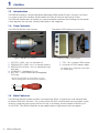
1.4 Case Contents
The HSM Jet Spindle case includes:
Figure 1: Spindle case content
1. NUT ER11 GHS - this is a standard nut
2. WRENCH ER11 SMS - this is a standard wrench*
3. WRENCH DIA 3.2x48 - this is a specialized shaft
lock tool*
4. ALLEN KEY - Hexagonal 2.0 mm
5. BATTERY - Lithium Metal non-rechargeable,
CR2 type
The wireless RPM display case includes:
Figure 2: Display case content
1. TSD - this is wireless RPM display
2. Universal AC/5VDC power supply
* For USA/Japan: include EU to US/Japan
AC adaptor plug
Ø 3.2
* Actual size and types of accessories may vary
due to configuration and manufacturing process
48
1.5 Main Features
The HSM Jet Spindle spindles are best used when high RPMs is required for small diameter tools
on limited RPM CNC machines. The system utilizes the CNC machine tool’s existing coolant supply
driven by a high pressure pump (minimum 20 bar) as an energy source to rotate a turbine up to
40.000 RPM. The HSM Jet Spindle can be supplied either as right-hand or left-hand option.
6
HSM Jet Spindle
GENERAL
1
The HSM Jet Spindle is not intended to replace the CNC machine spindle, but rather to upgrade the
existing CNC machine, providing improved performance, faster machining, better surface quality, and
extended tool life.
The new spindles can be used for semi-finish and finish machining applications such as milling,
drilling, and jig grinding.
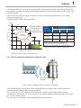
HSM Jet Spindle models operating ranges:
KRPM
krpm
60
Rotating speed
50
Machining conditions
for cutting speeds of
180 m/min in steel
TJS 40K
0.2-1.5 mm
40
TJS 40K-…
machine spindle
2
3
30 bar
40 bar
4
Diameter of cutting tool
5
40.000 rpm 50.000 rpm 60.000 rpm
* approximate RPM values - depend on
pressure, flow rate and used coolant type
Figure 4: The relation between coolant pressure
& RPM value based on HSM jet spindle types
10
1
20 bar
TJS 30K-…. 30.000 rpm 40.000 rpm 50.000 rpm
TJS 20K
2.6-3.5 mm
20
Coolant pressure
TJS 20K-…. 20.000 rpm 30.000 rpm 40.000 rpm
TJS 30K
1.6-2.5 mm
30
HSM jet
spindle
type / RPM
6
mm
Figure 3: Rotation speed vs. tool diameter
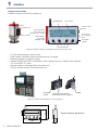
1.5.1 Wireless Rotation Speed Display general view:
RPM wireless
transmitter
Figure 5: HSM Jet Spindle wireless transmitter and display
The HSM Jet Spindle is equipped with an integrated wireless display system, allowing real-time
monitoring of the rotating speed during machining.
This system consists of a transmitter installed on the spindle housing, and a receiver display.
The receiver is powered by a 5 VDC universal AC/DC power adaptor connected to either a 220 VAC
or a 110 VAC power source.
The transmitter is powered by an exchangeable CR2 lithium battery.
HSM Jet Spindle
7
1
GENERAL
Display information
Wireless display and RPM transmitter unit
Spindle RPM
LCD screen
RPM
transmitter unit
Power switch
on/off
Signal readout
Transmitter unit
identification number
Unit ID number
Transmitter
unit's battery
level
RPM wireless
transmitter
detection side
DC power
socket
Function buttons
Figure 6: Wireless display and RPM transmitter unit main view
•
•
•
•
•
•
2.4 GHz radio frequency transmission
Direct wireless rotational speed monitoring up to 5 m range
Externally powered a receiver display
Enables reading of all HSM Jet Spindle systems being used on a specific CNC machine
This is limited to 127 tools
Internally battery's powered RPM transmitter unit
Own ID number for each RPM transmitter unit
DC power
socket
Figure 7: Wireless RPM display mounting options
1
8
REV.
01
2
DESCRIPTION
REVISIONS
4
3
DATE
6
5
7
8
B
113.5
B
80
A
106
Receiver display dimensions
C
D
Stand
APPROVED
A
32
nt is proprietary to Colibri spindles Ltd. and may not be used for manufacture or any other purpose without the written consent of Colibri spindles Ltd.
ZONE
Attach to the machine
pannel by built-in magnets
C
30.8
130
HSM Jet Spindle
E
SURFACE
DIMENSIONS
PROJECTION
D
GENERAL
1
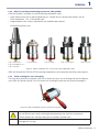
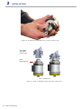
1.5.2 Built-in and Direct Mounting System to CNC Spindle
HSM Jet Spindle is available in several mounting adaptation types:
•
•
ER32 collet chuck with a special tightening nut, suitable for all standard tool holders with an
ER32 adaptation - This is the default type.
Integral options with various adaptations are available upon request.
Illustration purposes only
TJS...K BT30/40...
TJS...K DIN69871 40...
TJS...K CAT40...
TJS...K ER32...
TJS...K ST20...
TJS...K HSK A63...
TJS...K C5/6...
Figure 8: HSM Jet Spindle with several mounting adaptation types
HSM Jet Spindle with ER32 or ST20 mounting adaptations can be provided with filters upon request.
1.5.3 Shaft Locking for Tool Clamping
The shaft lock mechanism provides you with a simple and easy way to change the tool installed on
your HSM Jet Spindle spindle. For instructions on installing the tool into the spindle see page 21.
Figure 9: HSM Jet Spindle with pin mechanism locked
!
Warning:
Do not hold the pin handle while tightening/loosening the shaft lock mechanism.
Failure to obey this warning might lead to a broken spindle shaft.
It is strictly prohibited to use the HSM Jet spindle if shaft lock hole’s protection plug is
damaged or missing.
HSM Jet Spindle
9
1
GENERAL
1.5.4 Integrated Coolant Nozzle System
The Integrated coolant nozzle system provides 3 main advantages:
• Direct jet coolant application
• Better and faster chip evacuation
• Prevents tool thermal shock
Figure 10: Integrated coolant nozzel system
1.5.5 Tool Clamping
The HSM Jet Spindle is compatible with ER11 collet chuck.
The assembly of rotating elements (collet, nut and tool) must be balanced to a G2.5 at 40,000 RPM.
We recommend that you use ER 11 high precision spring collets.
When longer overhang is required, 10 & 25 mm long ER11 thermal shrink collets are available.
NUT ER11 GHS
Collet ER11 SPR
NUT ER11 GHS
+10 mm
+15 mm
NUT ER11 GHS
ER11 SRK ...10
Thermal Collet
Figure 11: Overhang solutions types
10 HSM Jet Spindle
ER11 SRK ...25
Thermal collet
INSTALLATION
2
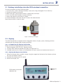
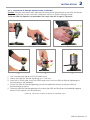
2.1 Battery installation into the RPM wireless transmitter
To install the battery into the RPM transmitter:
1. Unscrew the 4 screws holding the battery case cover using a hexagonal 2 mm Allen key.
2. Remove the battery case cover.
3. Make sure the O-ring inside the cover is seated well, and intact.
4. Put in the CR2 lithium battery in correct direction
5. Return the battery case cover to its place.
6. Fasten the battery case cover with the 4 screws that were removed.
Now the transmitter is ready to work.
Figure 12: Battery case open
2.2 Display
The HSM Jet Spindle is equipped with an integrated wireless display system, allowing real-time
monitoring of the rotating speed during machining.
2.2.1 Prerequisites for display installation
Make sure that the following pre-requisites are met:
1. Electrical power: 220/110 VAC, standard socket.
2. Distance from HSM Jet Spindle to Display: no more than 5 m.
3. Available space for the display so that operator will have a close and unobstructed view of it.
2.2.2 Display Workspace Installation
1. Mount the display onto a metallic surface using the magnet on the back of the display, or place
on a flat and leveled surface.
2. Connect the display to an AC socket.
3. Switch the display ON.
ON
RPM wireless transmitter
detection side
Figure 13: Switch display ON
HSM Jet Spindle 11
2
INSTALLATION
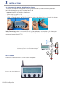
2.2.3 Connect the HSM Jet Spindle to the display
The display and the HSM Jet Spindle must be connected (paired) so they can "identify" each other.
Each transmitter unit has an own ID number (See Fig. 6)
To connect the HSM Jet Spindle to the display:
1. Make sure the display is ON.
2. Press 'CONNECT' on the display panel, then slide the transmitter (assembled on the
HSM Jet Spindle) across the left side (detection side) of the display unit, as shown in the picture.
Note: Connecting feature is the turning ON of the internal battery consumption on the transmitter
unit. To save a battery energy and in case that HSM jet Spindle is not in use - do Disconnection
procedure (see paragraph 2.2.5)
Figure 14: Many HSM Jet Spindles (not working
simultaniusly) can be connected to one display
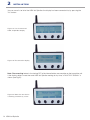
2.2.4
Screens
When turned on NO SIGNAL / 0 RPM screen will appear.
Figure 15: No signal displayed
12 HSM Jet Spindle
INSTALLATION
2
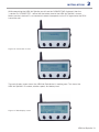
While connecting the HSM Jet Spindle you will see the CONNECTING displayed, then the
"<device ID> CONNECTED - notice that the battery level of the HSM Jet Spindle is shown.
Make sure that <device ID> on connected screen corresponds to the ID # signed onto the RPM
transmitter unit.
Figure 16: Connection screens
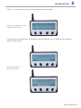
The main display screen shows the HSM Jet Spindle that is working now. This shows the
HSM Jet Spindle’s ID number, rotation speed, and battery level.
Figure 17: Main display screen
HSM Jet Spindle 13
2
INSTALLATION
You can see a list of all of the HSM Jet Spindles the display has been connected to, by pressing the
"list" button.
Figure 18: List of connected
HSM Jet Spindles display
Figure 19: Disconnection display
Note: Disconnecting feature is the turning OFF of the internal battery consumption on the transmitter unit.
If the display detects more than one HSM Jet Spindle working at any time, a "MULTIPLE SIGNAL" is
shown (see Fig.20).
Figure 20: More than one device
is working simultainusly screen
14 HSM Jet Spindle
INSTALLATION
2
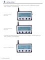
Select "List" to choose the device to disconnect from the next screen.
Figure 21: Disconnection list for
multiple signals screen
The display can be cleared from all connected HSM Jet Spindles, or a list of previously connected
devices can be viewed.
Figure 22: Disconnect
all sensors screens
HSM Jet Spindle 15
2
INSTALLATION
If the connect or disconnect processes don’t succeed for any reason, an appropriate message is
shown - see page 27 for troubleshooting.
Figure 23: Connection
failed screen
Figure 24: Disconnection
failed screen
If the battery of the HSM Jet Spindle you are currently using is running low - the following warning is
shown - see page 27 for troubleshooting.
Figure 25: Low battery screen
16 HSM Jet Spindle
INSTALLATION
2
If the HSM Jet Spindle is not spinning fast enough, the "LOW RPM" alert is shown.
Figure 26: Low RPM screen
If the HSM Jet Spindle is spinning too fast, the "HIGH RPM" alert is shown.
Figure 27: High RPM screen
2.2.5 Disconnect the HSM Jet Spindle from the display
1. Make sure the display is ON.
2. Press 'DISCONNECT' on the display panel, then slide the transmitter (assembled on the
HSM Jet Spindle) across the left side (detection side) of thedisplay unit, as shown in the picture.
While disconnecting the HSM Jet Spindle you will see the "Disconnecting" screen.
"<device ID> disconnected screen" - notice that the battery level of the HSM Jet Spindle is shown.
Make sure that <device ID> on disconnected screen corresponds to the ID # signed onto the RPM
transmitter unit.
HSM Jet Spindle 17
2
INSTALLATION
2.3 HSM Jet Spindle
2.3.1 Prerequisites for the CNC Machine
1. Coolant flow through the main CNC machine spindle
2. Minimum coolant pressure, at main machine spindle outlet: 20 bar
3. Maximum coolant pressure, at main machine spindle outlet: 40 bar
4. Minimum flow rate: 12 L/min, Operating coolant flow rate: 12-18 l/min
5. Minimum coolant filtration level: 100 µm
6. An active mist collector
7. With the emulsion coolant, use an anti-foaming agent additive suitable for your emulsion to
prevent foaming.
8. Use emulsion coolant with oil percentage higher than 4%
9. With oil coolant, the high pressure increases the amount of oil fumes:
a. Use appropriate means of fire protection and extinguishing.
b. Use anti-dissolution additive suitable for your oil.
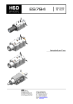
2.3.2 HSM Jet Spindle Installation onto the CNC Machine
Figure 28: HSM Jet Spindle on CNC machine
While the HSM Jet Spindle is mounted on the machine, the CNC machine spindle should be
stationary, except for tool checking procedure or Z-offset measurement. In those cases it must not
exceed 3000 RPM, or risk breaking/injury.
To avoid the CNC machine spindle rotation during the HSM Jet Spindle operation use the correct
software M-code to lock the Spindle orientation.
For example: "M19" code locks the spindle in a defined angle position.
Before installing a HSM Jet Spindle with a filter on the machine spindle, make sure that the filter is clean.
18 HSM Jet Spindle
INSTALLATION
2
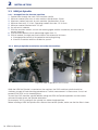
2.3.3 Placement of HSM Jet Spindle in the Toolholder
Caution: Deviation from these steps might lead to locking of the tightening nut to the HSM Jet Spindle.
The HSM Jet Spindle will only work with a toolholder that has a coolant through channel.
To fix the HSM Jet Spindle in a toolholder: See steps from left to right in Figure 29.
X1.5
1
2
3
4
5
1. Use a standard tool holder with ER32 collet chuck
2. Loosen the HSM Jet Spindle tightening nut 1.5 full turns
3. Insert built-in ER32 taper shank into ER32 collet chuck until the HSM Jet Spindle tightening nut
will be placed on the toolholder
4. Fasten the HSM Jet Spindle tightening nut onto the toolholder, without turning the HSM Jet
Spindle relative to the nut
5. Fasten the HSM Jet Spindle tightening nut to clamp the HSM Jet Spindle and the toolholder together
with an ER 32 spanner, use hand force only
Figure 29: Placement of HSM Jet Spindle in toolholder steps
HSM Jet Spindle 19
2
INSTALLATION
Figure 30: Example of a toolholder with a hole for coolant flow
Tool Holder
with ER32
collet chuck
ER32
Mounting Nut
TJS ...K-ER32 R/L
Figure 31: HSM Jet Spindle holding with ER32 collet chuck
20 HSM Jet Spindle
INSTALLATION
2
2.3.4 Tool prerequisites
HSM Jet Spindle spindles are for applications requiring tool shank diameters of up to 7 mm.
Application
Maximum tool working diameter, Ø [mm]
Slotting: ae ≤ 3.0 mm & ap = 0.1 D
Milling
Shouldering: ØD ≤ 3.5 mm, ae =1 D & ap = 0.25 D
Drilling
Max. Ø 2.0 mm
Jig grinding
Max. Ø 10.0 mm
Thread milling
Max. M5 (ISO), RH or LH rotation, solid cirbide
Chamfering & engraving
Up to 7 mm tool shank.
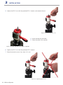
2.3.5 Tool Installation into the HSM Jet Spindle
The HSM Jet Spindle can hold various tools that use an ER11 collet.
To set a tool into the HSM Jet Spindle
1. Insert the WRENCH DIA 3.2x48 in the shaft lock hole, on the side
of the spindle.
Figure 32: Inserting the
WRENCH DIA 3.2x48
into the HSM Jet Spindle
2. Turn the shaft, while pushing the WRENCH DIA 3.2x48
in, toward the center of the HSM Jet Spindle, until the
WRENCH DIA 3.2x48 handle reaches the HSM Jet Spindle.
Figure 33: WRENCH DIA 3.2x48
in HSM Jet Spindle
!
Warning:
Do Not hold the WRENCH DIA 3.2x48 (shaft lock pin) handle while tightening/loosening
the ER11 nut. Failure to obey this warning might lead to a broken spindle shaft.
HSM Jet Spindle 21
2
INSTALLATION
3. Loosen the ER11 nut with the provided ER11 wrench, and remove the nut.
Figure 34: Loosening ER11 nut
4. Insert the tool into the collet.
5. Place the collet in the spindle.
Figure 35: Collet and tool in the HSM Jet Spindle
6. Tighten the ER11 nut with the provided ER11 wrench.
7. Check that total run out is less than 0.01 mm.
Figure 36: Tightening ER11 nut
22 HSM Jet Spindle
INSTALLATION
2
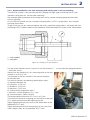
2.3.6 Recommendations for tool clamping and cutting tool’s run-out checking
The HSM Jet spindle is very precision product, designed for high speed machining with a small
diameter cutting tools for the accurate machining.
We attached great importance to the cutting tool’s setup, correct clamping procedure and tool’s
run-out cheching.
On the HSM Jet spindle we use a standard clamping tools, as ER11 spring collets and standard
clamping accessories.
To get a minimum run-out value we propose the using a precised spring collects with exact hole size.
According to ISO 15488 the collet run-out tolerances should be checked as shown at the sketch below.
1 - test mandrel
a - test point
Figure 36: Testing of run-out tolerance
For tool shank diameter from 3.0 up to 6.0 mm the distance “L” - run-out measure gauge placement
- should be 16 mm.
Allowed run-out tolerance at this measuring point on the test
mandrel is up to 0.01 mm.
The diameter of the test mandrel is the nominal diameter
of the collet hole.
For the test mandrel, the following specifications apply:
a) diameter tolerance: h6
b) cylindricity: 0,002 mm
c) parallelism: 0,002 mm
d) roundness: 0,002 mm
e) surface without longitudinal marks
f) maximum surface roughness Rz = 4 μm
g) surface hardness: (about 58 HRc)
The recommended torque for ER11 nut is 8-10 Nm.
The maximum torque for clamping nut shall not be more than
25% above the recommended tightening torque.
Higher tightening torque may result in the deformation of the
toolholder (ER11 seat).
Higher clamping force of the clamping nut at the same time
means higher stress on the toolholder (ER11 seat).
HSM Jet Spindle 23
3
MAINTENANCE
3.1 Periodic Maintenance
The HSM Jet Spindle is free of periodic maintenance.
3.2 Change Battery on RPM Transmitter
The battery in the RPM transmitter mounted on your HSM Jet Spindle will be drained over time.
To change the battery please make procedure as in chapter 2 (Installation p. 11)
3.3 Operation Conditions
•
•
Operation temperature range: 15-30° C
Altitude: 2000 m
3.4 Storage
3.4.1 Pre-Storage
Before storing the HSM Jet Spindle:
• Clean the HSM Jet Spindle with an air blow for 10-15 sec.
• Disconnect the HSM Jet Spindle from the display that it is connected to.
• Place the HSM Jet Spindle in its case.
3.4.2 Conditions
The HSM Jet Spindle must be stored in conditions meeting the following requirements:
• Sheltered from possible adverse weather conditions.
• Ideal Storage Temperature Range: 15 ºC to 27 ºC.
• Humidity Range: 30% to 60% relative humidity (RH)
!
Warning:
It is strictly prohibited immerse the HSM Jet Spindle in a fluid bath.
It is strictly prohibited to use the cleanser, different from the coolant, allowed for using
on HSM Jet Spindle.
Any damage caused by one of the above “Warnings” will not be covered by limited
warranty
24 HSM Jet Spindle
WORKING WITH THE HSM Jet Spindle
4
The HSM Jet spindle system was developed to create machining conditions that would enable
applying optimal cutting speed conditions for small diameter solid carbide tools requiring high RPM.
The HSM Jet spindle rotates at its rated speed when idle. When the cutting tool enters the
workpiece, it is expected that the rotation speed might slow down by several thousand RPM.
If the HSM Jet spindle rotation speed drops by more than several thousand RPM, when the cutting
tool enters the workpiece, review the cutting process parameters and adjust them accordingly.
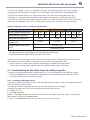
HSM Jet Spindles types vs. Cutting tool diameter:
HSM Jet spindle type
TJS 20K…
Rotational Spindle speed [Krpm ]*
20
Coolant pressure range [bar]**
20
TJS 30K…
30
40
30
30
40
20
TJS 40K…
40
50
40
30
40
20
50
60
30
40
Coolant flow rate range [l/min]
12-18
12-18
12-18
Recommended Cutting tool
diameter [mm]
2.0-3.5
1.0 -2.5
0.2-1.5
Recommended cutting speed
[m/min]
for steel <_ 200
for aluminum <_ 200
* aproximattely rotational spindle speed
20 Krpm based on Min. coolant pressure 20 bar & Min. flow rate 12 l/min
** recommended coolant pressure 30-40 bar, flow rate 18 l/min
In order to use the advantages of high speed machining, minimize cutting forces and reduce wear,
tool diameter should be selected according to the spindle speed (when possible).
•
•
Always select the smallest tool diameter, according to the application requirements.
Always select cutting tools in grades that are suitable for high speed machining.
4.1 Recalculating of the Table Feed for HSM Jet spindle
There are two calculating methods of table feed F [mm / min], operating with the HSM Jet spindle:
• Existing machining process (transition from machining with a machine spindle to an HSM Jet spindle)
• In case of selecting a new machining process
4.1.1 Existing machining process:
The feed per tooth fz remains constant while the table feed F increases in the same proportion to the
HSM Jet Spindle rotation speed.
The feed per tooth fz should remain constant while the table feed F is changed.
Calculate the table feed F [mm/min] according to the following formula:
F ≈ Ratio x F current
F - the new table feed.
Ratio - Is the ratio between the machine spindle speed and HSM Jet spindle speed, meaning the
new speed divided by the current speed.
F current - the current table feed that you would use with your machine.
HSM Jet Spindle 25
4
WORKING WITH THE HSM Jet Spindle
For example:
If using machine spindle at 8,000 RPM, and the table feed was 160 [mm/min], and you set
HSM Jet spindle to 30,000 RPM, then we suggest that your new table feed be:
New table feed = 30,000/8,000 x 160=3.75 x 600 [mm/min].
In this example your new table feed should be 600 mm/min.
4.1.2 New machining process
Calculate the table speed F [mm/min] according to the formula:
F = n x z x fz
Rotating speed - n [RPM] The rotating speed for table speed calculation will be determined only
after reading the actual rotation speed obtained when the tool has engaged the material.
Number of teeth - z
Feed per tooth - fz [mm/tooth] - Select according to the tool’s vendor recommendations, taking into
consideration the machining material, the application and the tool geometry.
Note:
For the first trial at both machining processes, it is recommended to increase the table feed gradually
by of 3.0-3.5 (not directly 3.75), before setting the table feed to the above calculated value.
26 HSM Jet Spindle
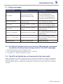
TROUBLESHOOTING
5
5.1 Display messages
Display message
Indicates that
Action required
NO SIGNAL
No connected HSM Jet
Spindle working in range
If no HSM Jet Spindle is currently at
work - no action required
If a HSM Jet Spindle is working wait 10 sec. If message persists
disconnect and then reconnect it.
MULTIPLE SIGNAL
More than one device is
working at once
Press LIST button, then disconnect
one of the HSM Jet Spindle
LOW RPM
HSM Jet Spindle is spinning
too slow
Check: HSM Jet Spindle, coolant
pressure, and cutting parameters
HIGH RPM
HSM Jet Spindle is spinning
too fast
Check: HSM Jet Spindle, and
coolant pressure
FAILED TO CONNECT
Connection did not succeed
Retry the connection process. Still
not working? Replace the HSM Jet
Spindle battery.
FAILED TO DISCONNECT
Disconnection did not succeed
Retry the disconnection process.
Still not working? Replace the HSM
Jet Spindle battery.
LOW BATTERY
Battery is low on power
Replace the battery
5.2 The HSM Jet Spindle shaft is not rotate or RPM does not correspond
correctly to coolant pressure (may result in "low RPM" message)
1. Check coolant and pressure in cooling system.
2. Run coolant through HSM Jet Spindle for 5 min. while idle.
3. If issue persists - call for technical assistance.
5.3 The HSM Jet Spindle has not been used in the last month
Before working with the HSM Jet Spindle that has not been used recently, run coolant through the
HSM Jet Spindle, when it is assembled on your CNC machine, for 3 to 5 min. Make sure that the
HSM Jet Spindle reaches a speed that corresponds to the pressure of the coolant that is pumped
through it.
HSM Jet Spindle 27
6
WARRANTY SUMMARY
LIMITED WARRANTY FOR HSM JET SPINDLE
1. This Limited Warranty ("Warranty") is given by Colibri Spindles Ltd., with registered office at
Industrial Park Lavon Building 1, M.P. Bikat Bet Hakerem 2011800, Israel, operating through
its designated affiliates and/or parties authorized by it in writing (hereinafter, all collectively and
each severally - "Colibri"), as dealer of the spindle for CNC machines known as SPINJET
or TYPHOON (the "Product"), to the customer contracting Colibri in respect of the Product
("Customer").
This Warranty shall apply, on the terms specified herein, to any contract, including, but not limited
to, contracts of sale, lease, license, placement or services, the subject matter of which is the
provision of the Product by Colibri to Customer, unless otherwise specifically agreed in writing
between the said parties.
2. Colibri warrants the Product to be free of defects in material and workmanship and to conform
to the applicable Colibri’s specifications, for a period of 12 months commencing on the date of
delivery of the Product to Customer (the "Warranty Period"), subject to normal use, storage and
application thereof in accordance with and based on Colibri’s standard tolerances, instructions
of use and recommendations and conform to the applicable specifications provided by Colibri.
Apparent defects shall be reported to Colibri in writing within 3 working days as of the Customer’s
receipt of the Product. Latent defects occurring within the Warranty Period shall be reported in
writing within 3 working days as of discovery.
3. During the Warranty Period, Colibri shall, at its option and sole discretion, either repair, replace,
or grant credit for, any Product and any component thereof, which are determined by it to be
defective pursuant to Section 2 above, at no additional charge to the Customer, and subject to
the entire terms and conditions set forth herein.
4. This Warranty does NOT cover any damage resulting from extraneous causes not attributable to
Colibri including, inter alia, accident or disaster, misuse, abuse, neglect or improper maintenance,
modification or alteration, or attempted unauthorized dismantling and/or repairs by the Customer
or any third party, wear or damage resulting from corrosion or processing of abrasive/aggressive
resins, damages resulting from operation of the product not within the working parameters and
working environment it was designed for, damages resulting from Customer’s non-compliance
with applicable laws, regulations, or by-laws, and standard industry practices, as well as any other
damage sustained due to causes beyond the reasonable control of Colibri.
5. This Warranty shall not apply in the event the Customer fails to pay for the Product in full and/or
on a timely basis as set out in any sale, license, lease, placement, or services agreement, or any
other legal instrument which has been executed by Colibri and the Customer, including, without
limitation, invoices issued by Colibri or its local authorized agent to Customer from time to time.
6. Warranty service may be obtained by returning the defective Product or any component thereof
during the Warranty Period to Colibri with proof of purchase and date of delivery. Any and all
repairs shall be carried out, and this Warranty shall accordingly cover only such repairs, at the
premises of Colibri and/or its local authorized agent and/or supplier. However, Colibri strongly
recommends that the Customer obtains preliminary support from Colibri by e-mail and/or
telephone prior to returning the Product to Colibri.
7. In case Customer desires to exercise its right under this Warranty, the Customer shall, at they
own and exclusive expense, place the Product at Colibri’s premises for inspection, and repair or
replacement, if necessary. The Customer shall bear all costs associated with the transportation of
the Product from the Customer’s premises to Colibri’s premises and back to Customer’s premises
once inspection and where required - repair or replacement, have been performed by Colibri.
8. Colibri retains the right to examine and inspect the Product once received from the Customer in
28 HSM Jet Spindle
WARRANTY SUMMARY
6
order to determine, inter alia, the cause of the alleged defect, and whether this Warranty applies.
9. Replacement parts shall be furnished on an exchange basis and may be either reconditioned or
new.All defective parts which were replaced hereunder shall become the property of Colibri.
10.THIS WARRANTY IS THE ONLY WARRANTY OFFERED BY COLIBRI AND IS IN LIEU
OF ANY IMPLIED WARRANTIES, INCLUDING BUT NOT LIMITED TO, WARRANTY OF
MERCHANTABILITY AND FITNESS FOR A PARTICULAR USE OR PURPOSE, ANY AND
ALL OF WHICH ARE HEREBY EXPRESSLY DISCLAIMED, DENIED AND EXCLUDED.
BY BUYING THE PRODUCT THE CUSTOMER AGREES AND ACKNOWLEDGES THAT THE
REMEDY AVAILABLE TO HIM AS SPECIFIED HEREIN, IS IN LIEU OF ANY REMEDIES THAT MAY BE
OTHERWISE AVAILABLE TO HIM, NOW OR IN THE FUTURE, WHETHER IN LAW OR IN EQUITY.
ANYTHING STATED HEREIN TO THE CONTRARY NOTWITHSTANDING, IN NO EVENT WILL
COLIBRI BE LIABLE FOR ANY SPECIAL, PUNITIVE, INCIDENTAL, EXEMPLARY OR
CONSEQUENTIAL DAMAGES (INCLUDING, BUT NOT LIMITED TO, LOSS OF ANY PROFIT,
BUSINESS, PRODUCTION OR REVENUE), NOR FOR INJURY TO PROPERTY, ARISING OUT
OF THE USE, MISUSE OR INABILITY TO USE THE PRODUCT, EVEN IF COLIBRI HAS BEEN
ADVISED OF THE POSSIBILITY OF SUCH DAMAGES OR LOSSES, OR FOR ANY CLAIM BY
ANY OTHER PARTY.
11.This Warranty, including any and all undertakings, guarantees or assurances provided herein by
Colibri, is specifically limited to the Customer, and not imputed by Colibri, whether directly or
indirectly, expressly or impliedly, to any other person or entity, including any subsequent buyer or
user, bailee, licensee, assignee, employee, or agent of Customer.
12.Your statutory rights are and shall remain unaffected by this Limited Warranty, all terms and
conditions of this Warranty are subject to the relevant law applicable in the jurisdiction in which
the Product was purchased, unless otherwise agreed by the parties in writing. If any provision
hereof is declared by any competent legal authority to be invalid or unenforceable for any reason
under applicable law, then such provision shall be reformed to the extent necessary to make it
valid and enforceable under that law. Every provision hereinabove is intended to be severable and,
if any term or provision hereof is determined to be illegal, invalid or unenforceable for any reason
whatsoever and cannot be reformed so as to be legal, valid and enforceable, such provision shall
be deemed severed herefrom and the illegality, invalidity or unenforceability of such provision shall
not affect the legality, validity and enforceability of the remainder of this Limited Warranty.
HSM Jet Spindle 29
7
CUSTOMER SERVICE AFTER PURCHASE
Whenever a malfunction cannot be solved by the solutions mentioned in the troubleshooting section,
you are requested to consult the Colibri representative for further assistance or instructions.
The unit should not be returned before receiving written approval from Colibri. The serial number for the
unit must be indicated on your claim form (you can find this information on the rear of the unit housing).
We hope this information will be helpful. Our goal is to provide the best possible service to our customers.
30 HSM Jet Spindle
FCC COMPLIANCE STATEMENT
8
This device has been tested and found to comply with the limits for a Class A digital device, pursuant
to Part 15 of the FCC Rules. These limits are designed to provide reasonable protection against
harmful interference in residential installations. This equipment generates uses and can radiate radio
frequency energy and, if not installed and used in accordance with the instructions, may cause
harmful interference to radio and television reception.
However, there is no guarantee that interference will not occur in a particular installation. If this device
does cause such interference, which can be verified by turning the device off and on, the user is
encouraged to eliminate the interference by one or more of the following measures:
- Re-orient or re-locate the receiving antenna.
- Increase the distance between the device and the receiver.
- Connect the device to an outlet on a circuit different from the one that supplies power to the receiver.
- Consult the dealer or an experienced radio/TV technician.
!
Warning:
Changes or modifications to this unit not expressly approved by the party responsible
for compliance could void the user’s authority to operate the equipment.
This device complies with FCC Rules Part 15: Operation is subject to two conditions: (1) This device
may not cause harmful interference, and (2) this device must accept any interference that may be
received or that may cause undesired operation.
To comply with FCC Section 1.310 for human exposure to radio frequency electromagnetic fields,
implement the following instruction:
A distance of at least 20 cm between the equipment and all persons should be maintained during the
operation of the equipment.
HSM Jet Spindle 31
S P I N D L E S
T E C H N O L O G Y
Colibri Spindles Ltd Industrial Park Lavon, Building 1, M.P. Bikat Bet Hakerem 2011800, Israel
Tel: +972-4-9089101 | Fax: +972-4-9589061 | [email protected] | www.colibrispindles.com
V.3 07/2015 | 27-188-078
CO L I B R I